Embed Size (px)
Citation preview
Type series booklet8526.12/18--10
AMTROBOX EEx iaAMTRONIC EEx ia
Ex ia IIC T6
Position monitoringand on/off pneumatic distribution functions
Intrinsically saferemote indication and control box
for ACTAIR and DYNACTAIRpneumatic actuators
and MR manual actuators
II 1 G0081
Applications Explosive atmospheres. All sectors of Water, Energy and Industry markets.
General information AMTROBOXEEx ia andAMTRONICEEx ia (R 1172) remoteindication and control boxes are of intrinsically safeprotection design for use in explosive atmospheres.
AMTROBOX EEx ia R 1172Specially designed for use with double acting ACTAIR andspring return DYNACTAIR pneumatic actuators and MRmanual actuators, this box integrates, in a modular form, thefollowing electric functions:-- Position detection (opening and closing) by microswitchesor inductive proximity detectors
-- Feed--back position by angle sensor and 4--20 mAtransmitter (option).
AMTRONIC EEx ia R 1172Specially designed for use with double acting ACTAIR andspring return DYNACTAIR pneumatic actuators, this boxensures the following functions:-- Position detection (opening and closing) by microswitchesor inductive proximity detectors,
-- Feed--back position by angle sensor and 4--20 mAtransmitter (option)
-- On/off pneumatic distribution. They are approved Ex ia IIC T6 in accordance with EN60079--0 and EN 60079--11 standards.EC type examination certificate: LCIE 03 ATEX 6435XThe representative gas of explosion risk is hydrogen, themaximum temperature of the box is 80 °C.
They are in accordance with ATEX 94/9/CE directive andmarking:
II 1 G0081
Explosive area: Ex ia IIC T6
It can to be fitted directly onto actuators by the intermediate ofit VDI/VDE 3845 interface.
It is equipped with a bicolor visual pointer large size allowingthe visualisation of the quater--turn valve position.
Protection Protection level: IP 67 Its cataphoresis coating ensures a good resistance incorrosive environments.
Temperature range From –10 °C to +50 °C
Material Housing: Aluminium. Base plate: Aluminium.
Standard variante Feed--back position.
This leaflet is also to be used as a start--up guide ref. 42 057 237
AMTROBOX EEx iaAMTRONIC EEx ia
2
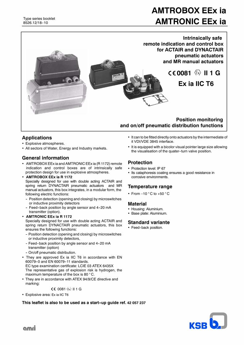
AMTROBOX EEx ia
Angle sensor (option)
Transparent sight glass
Pointer
Adjustable cams
Microswitches orinductive proximity detectorson supporting plate
4--20 mA transmitter (option)
External earth terminal
AMTROBOX EEx iaAMTRONIC EEx ia
3
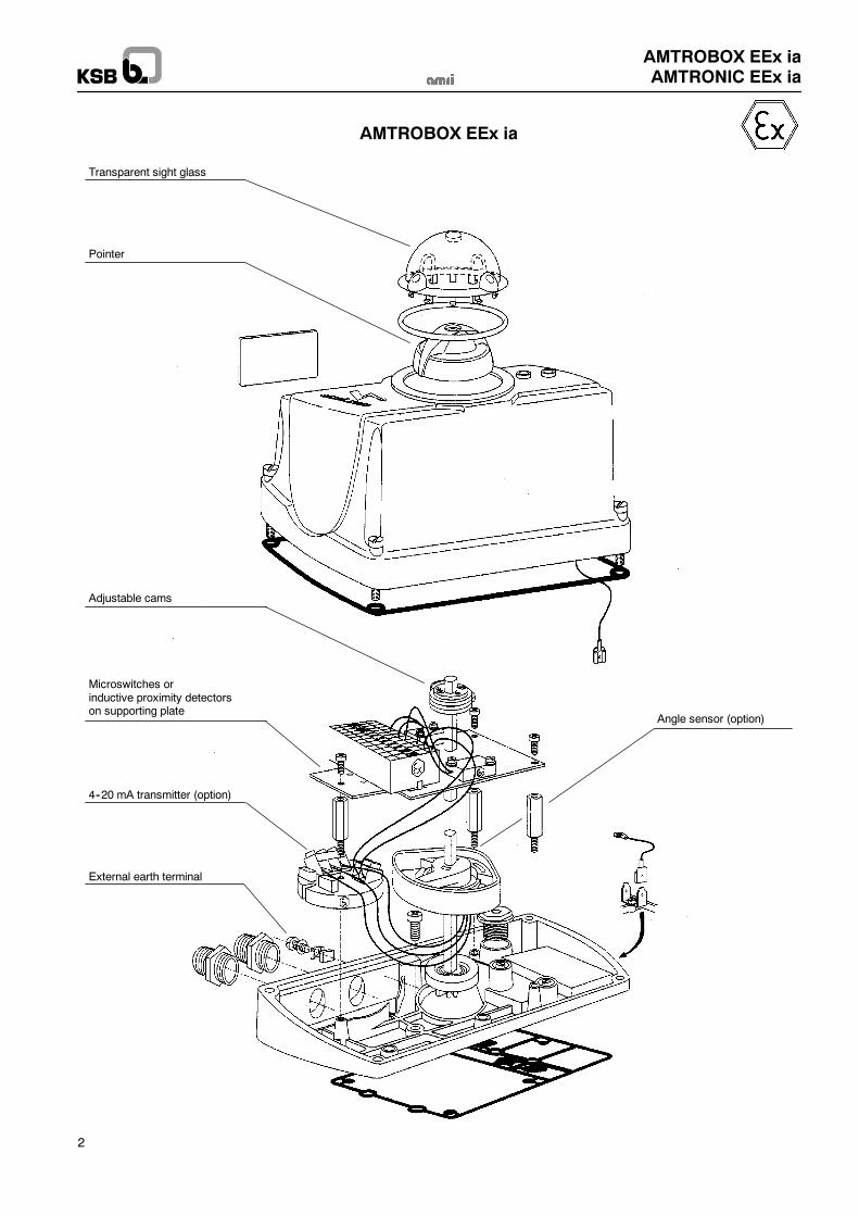
Transparent sight glass
Pointer
Push--buttonsfor emergency controlof the electric pilots
Electric pilots
Angle sensor (option)
Pneumaticvalves
Microswitches orinductive proximity detectorson supporting plate
4--20 mA transmitter (option)
External earth terminal
Operating timeadjustment
Adjustable cams
AMTRONIC EEx ia
AMTROBOX EEx iaAMTRONIC EEx ia
4
Contents
Page
General technical data 5
Overall dimensions and weight 5
Parts common to all versions 6
Position detection: AMTROBOX EEx ia and AMTRONIC EEx ia-- General 8-- Construction 8
By microswitches -- Boxes ref. R 1172--A2....-- Technical characteristics of microswitches 9-- Wiring diagram 9-- Barriers and interfaces 9
By inductive proximity detectors -- Boxes ref. R 1172--K3.... and R 1172--J7....-- Technical characteristics of detectors 10-- Wiring diagram 10-- Barriers and interfaces 10
On/off pneumatic distribution: AMTRONIC EEx ia-- Construction 11-- Various available configurations 12-- Technical data of electro--pneumatic valve -- Wiring diagram -- Barriers and interfaces 13
Optional feed--back position 0° to 90° by a 4--20 mA signal 14
Pneumatic supply 15
Commissioning-- Warning 16-- Electric connection 16-- Pneumatic connection 16-- Operating time adjustment (AMTRONIC EEx ia) 17-- Open/close position detection adjustment 17-- Angle sensor adjustment 18-- 4--20 mA feed--back adjustment 18
Declaration of conformity 19
Product features 20
AMTROBOX EEx iaAMTRONIC EEx ia
5
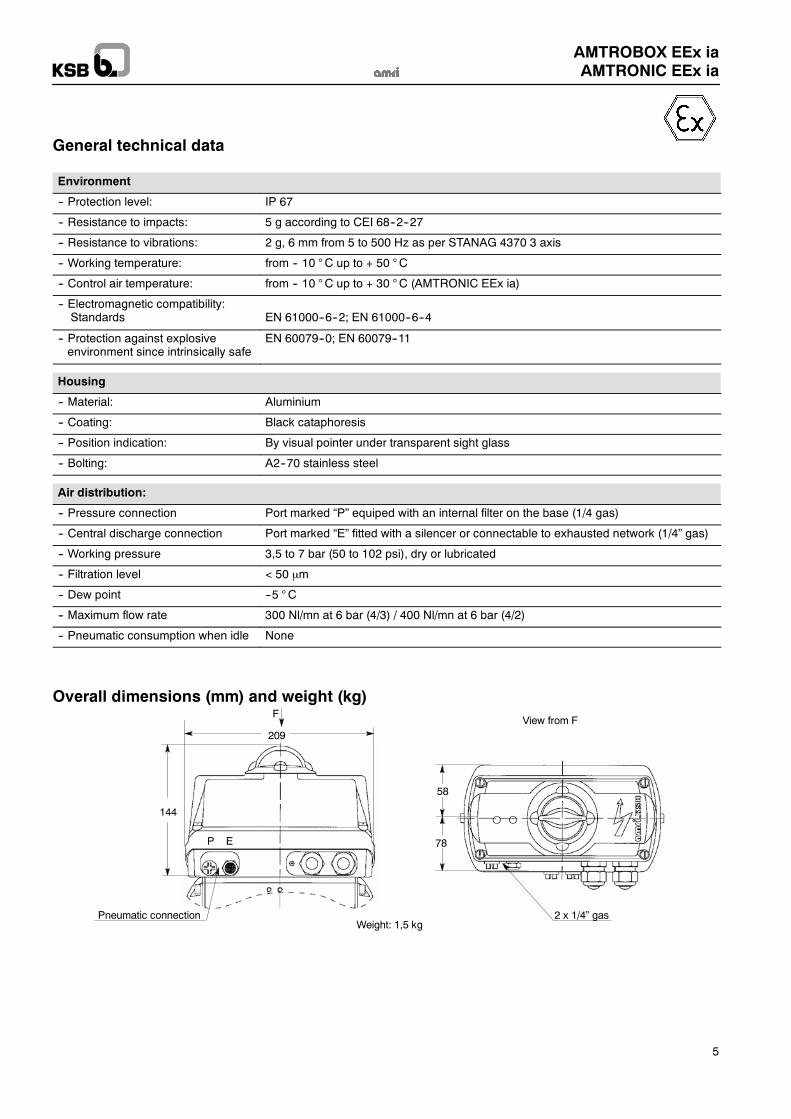
General technical data
Environment
-- Protection level: IP 67
-- Resistance to impacts: 5 g according to CEI 68--2--27
-- Resistance to vibrations: 2 g, 6 mm from 5 to 500 Hz as per STANAG 4370 3 axis
-- Working temperature: from -- 10 °C up to + 50 °C
-- Control air temperature: from -- 10 °C up to + 30 °C (AMTRONIC EEx ia)
-- Electromagnetic compatibility:Standards EN 61000--6--2; EN 61000--6--4
-- Protection against explosiveenvironment since intrinsically safe
EN 60079--0; EN 60079--11
Housing
-- Material: Aluminium
-- Coating: Black cataphoresis
-- Position indication: By visual pointer under transparent sight glass
-- Bolting: A2--70 stainless steel
Air distribution:
-- Pressure connection Port marked “P” equiped with an internal filter on the base (1/4 gas)
-- Central discharge connection Port marked “E” fitted with a silencer or connectable to exhausted network (1/4” gas)
-- Working pressure 3,5 to 7 bar (50 to 102 psi), dry or lubricated
-- Filtration level < 50 m
-- Dew point --5 °C
-- Maximum flow rate 300 Nl/mn at 6 bar (4/3) / 400 Nl/mn at 6 bar (4/2)
-- Pneumatic consumption when idle None
Overall dimensions (mm) and weight (kg)
58
78
Weight: 1,5 kg
View from F209
F
144
Pneumatic connection 2 x 1/4” gas
P E
AMTROBOX EEx iaAMTRONIC EEx ia
6
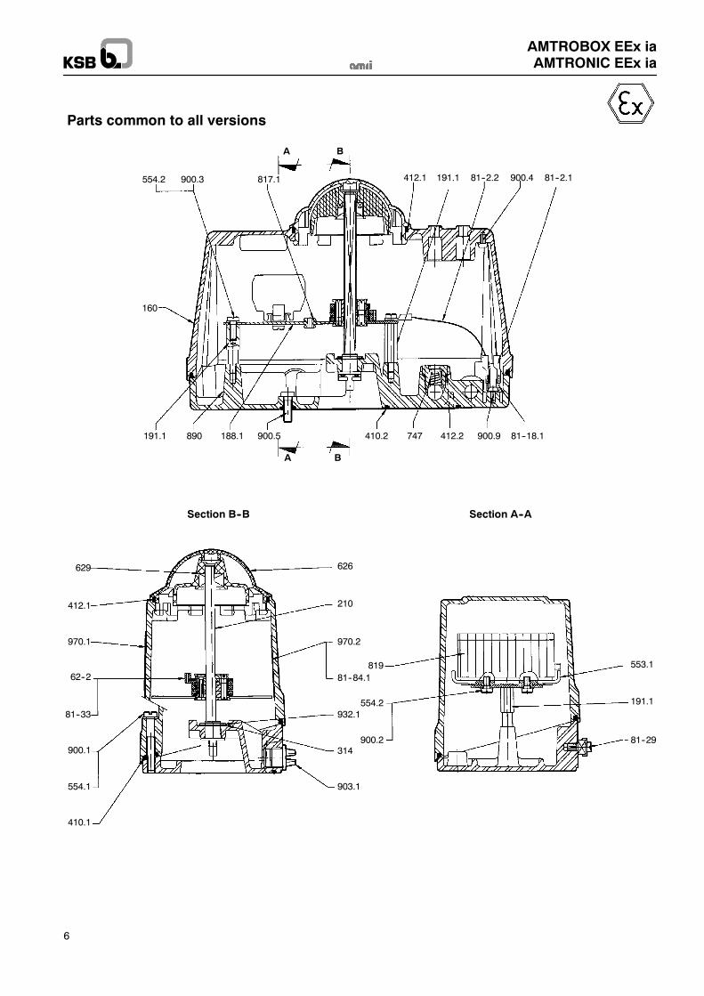
Parts common to all versions
554.2 900.3 817.1 412.1 191.1 81--2.2 900.4 81--2.1
160
191.1 890 188.1 900.5 410.2 747 412.2 900.9 81--18.1
A
A
B
B
819
554.2
900.2
553.1
191.1
81--29
626
210
970.2
81--84.1
629
412.1
970.1
62--2
81--33
900.1
554.1
410.1
932.1
314
903.1
Section B--B Section A--A
AMTROBOX EEx iaAMTRONIC EEx ia
7
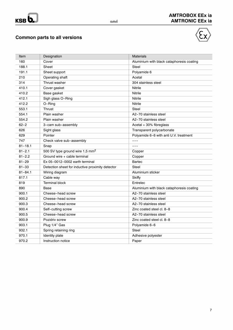
Common parts to all versions
Item Designation Materials
160 Cover Aluminium with black cataphoresis coating
188.1 Sheet Steel
191.1 Sheet support Polyamide 6
210 Operating shaft Acetal
314 Thrust washer 304 stainless steel
410.1 Cover gasket Nitrile
410.2 Base gasket Nitrile
412.1 Sigh glass O--Ring Nitrile
412.2 O--Ring Nitrile
553.1 Thrust Steel
554.1 Plain washer A2--70 stainless steel
554.2 Plain washer A2--70 stainless steel
62--2 3--cam sub--assembly Acetal + 30% fibreglass
626 Sight glass Transparent polycarbonate
629 Pointer Polyamide 6--6 with anti U.V. treatment
747 Check valve sub--assembly ------
81--18.1 Snap ------
81--2.1 500 SV type ground wire 1,5 mm2 Copper
81--2.2 Ground wire + cable terminal Copper
81--29 Ex 05--0012--0002 earth terminal Bartec
81--33 Detection sheet for inductive proximity detector Steel
81--84.1 Wiring diagram Aluminium sticker
817.1 Cable way Skiffy
819 Terminal block Entrelec
890 Base Aluminium with black cataphoresis coating
900.1 Cheese--head screw A2--70 stainless steel
900.2 Cheese--head screw A2--70 stainless steel
900.3 Cheese--head screw A2--70 stainless steel
900.4 Self--cutting screw Zinc coated steel cl. 8--8
900.5 Cheese--head screw A2--70 stainless steel
900.9 Pozidriv screw Zinc coated steel cl. 8--8
903.1 Plug 1/4’’ Gas Polyamide 6--6
932.1 Spring retaining ring Steel
970.1 Identity plate Adhesive polyester
970.2 Instruction notice Paper
AMTROBOX EEx iaAMTRONIC EEx ia
8
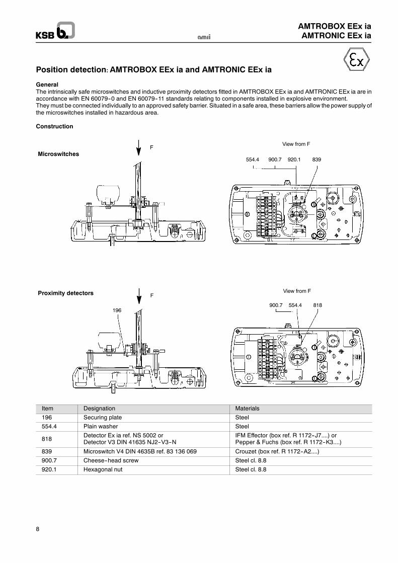
Position detection: AMTROBOX EEx ia and AMTRONIC EEx ia
GeneralThe intrinsically safe microswitches and inductive proximity detectors fitted in AMTROBOX EEx ia and AMTRONIC EEx ia are inaccordance with EN 60079--0 and EN 60079--11 standards relating to components installed in explosive environment.They must be connected individually to an approved safety barrier. Situated in a safe area, these barriers allow the power supply ofthe microswitches installed in hazardous area.
Construction
554.4 900.7 920.1 839
View from FF
900.7 554.4 818196
FView from F
Microswitches
Proximity detectors
Item Designation Materials
196 Securing plate Steel
554.4 Plain washer Steel
818Detector Ex ia ref. NS 5002 orDetector V3 DIN 41635 NJ2--V3--N
IFM Effector (box ref. R 1172--J7....) orPepper & Fuchs (box ref. R 1172--K3....)
839 Microswitch V4 DIN 4635B ref. 83 136 069 Crouzet (box ref. R 1172--A2....)
900.7 Cheese--head screw Steel cl. 8.8
920.1 Hexagonal nut Steel cl. 8.8
AMTROBOX EEx iaAMTRONIC EEx ia
9
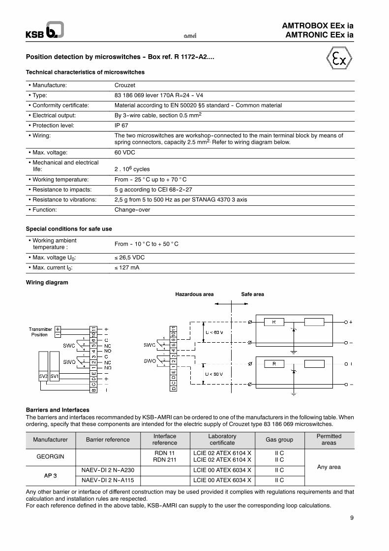
Position detection by microswitches -- Box ref. R 1172--A2....
Technical characteristics of microswitches
Manufacture: Crouzet
Type: 83 186 069 lever 170A R=24 -- V4
Conformity certificate: Material according to EN 50020 §5 standard -- Common material
Electrical output: By 3--wire cable, section 0.5 mm2
Protection level: IP 67
Wiring: The two microswitches are workshop--connected to the main terminal block by means ofspring connectors, capacity 2.5 mm2. Refer to wiring diagram below.
Max. voltage: 60 VDC
Mechanical and electricallife: 2 . 106 cycles
Working temperature: From -- 25 °C up to + 70 °C
Resistance to impacts: 5 g according to CEI 68--2--27
Resistance to vibrations: 2,5 g from 5 to 500 Hz as per STANAG 4370 3 axis
Function: Change--over
Special conditions for safe use
Working ambienttemperature : From -- 10 °C to + 50 °C
Max. voltage U0: 26,5 VDC
Max. current I0: 127 mA
Wiring diagram
Hazardous area Safe area
Barriers and InterfacesThe barriers and interfaces recommanded by KSB--AMRI can be ordered to one of the manufacturers in the following table.Whenordering, specify that these components are intended for the electric supply of Crouzet type 83 186 069 microswitches.
Manufacturer Barrier referenceInterfacereference
Laboratorycertificate Gas group
Permittedareas
GEORGINRDN 11RDN 211
LCIE 02 ATEX 6104 XLCIE 02 ATEX 6104 X
II CII C
A
AP 3NAEV--DI 2 N--A230 LCIE 00 ATEX 6034 X II C Any area
AP 3NAEV--DI 2 N--A115 LCIE 00 ATEX 6034 X II C
Any other barrier or interface of different construction may be used provided it complies with regulations requirements and thatcalculation and installation rules are respected.For each reference defined in the above table, KSB--AMRI can supply to the user the corresponding loop calculations.
AMTROBOX EEx iaAMTRONIC EEx ia
10
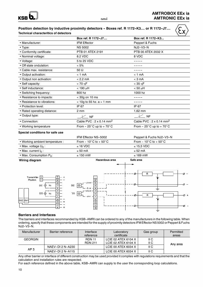
Position detection by inductive proximity detectors -- Boxes ref. R 1172--K3.... or R 1172--J7....Technical characteritics of detectors
Box ref. R 1172--J7.... Box ref. R 1172--K3... Manufacturer: IFM Effector Pepperl & Fuchs
Type: NS 5002 NJ2--V3--N
Conformity certificate: PTB 01 ATEX 2191 PTB 00 ATEX 2032 X
Nominal voltage: 8.2 VDC 8 VDC
Voltage: 5 to 25 VDC ----------
Off state ondulation: < 5% ----------
Cable max. resistance: 50 ----------
Output activation: < 1 mA < 1 mA
Output non activation: < 2.2 mA < 3 mA
Self capacity: < 70 F < 35 F
Self inductance: < 190 H < 50 H
Switching frequency: 800 hz 1000 hz
Resistance to impacts: < 30g on 10 ms ----------
Resistance to vibrations: < 10g to 55 hz. a = 1 mm ----------
Protection level: IP 67 IP 67
Rated operating distance: 2 mm 1,62 mm
Output type: NF NF
Connection: Cable PVC : 2 x 0.14 mm2 Cable PVC : 2 x 0.14 mm2
Working temperature From -- 25°C up to + 70°C From -- 25°C up to + 70°C
Special conditions for safe use
IFM Effector NS--5002 Pepperl & Fuchs NJ2--V3--N
Working ambient temperature : From -- 10°C to + 50°C From -- 10°C to + 50°C Max. voltage U0 : 16 VDC 15,5 VDC
Max. current I0 : 50 mA 52 mA
Max. Consumption P0: 150 mW 169 mW
Hazardous area Safe areaWiring diagram
Nc
Nc
Barriers and InterfacesThe barriers and interfaces recommanded by KSB--AMRI can be ordered to any of the manufacturers in the following table.Whenordering, specify that these components are intended for the supply of proximity detectors IFMEffectorNS5002 orPepperl &FuchsNJ2--V3--N.
Manufacturer Barrier reference Interfacereference
Laboratorycertificate
Gas group Permittedareas
GEORGIN RDN 11RDN 211
LCIE 02 ATEX 6104 XLCIE 02 ATEX 6104 X
II CII C Any area
AP 3NAEV--DI 2 N--A230 LCIE 00 ATEX 6034 X II C
Any area
AP 3NAEV--DI 2 N--A115 LCIE 00 ATEX 6034 X II C
Any other barrier or interface of different construction may be used provided it complies with regulations requirements and that thecalculation and installation rules are respected.For each reference defined in the above table, KSB--AMRI can supply to the user the corresponding loop calculations.
AMTROBOX EEx iaAMTRONIC EEx ia
11
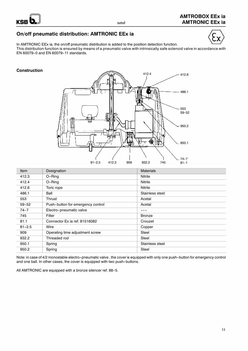
On/off pneumatic distribution: AMTRONIC EEx ia
In AMTRONIC EEx ia, the on/off pneumatic distribution is added to the position detection function.This distribution function is ensured by means of a pneumatic valve with intrinsically safe solenoid valve in accordance withEN 60079--0 and EN 60079--11 standards.
412.4 412.6
486.1
55359--52
950.2
950.1
74--781--181--2.5 412.3 909 932.2 745
Construction
Item Designation Materials
412.3 O--Ring Nitrile
412.4 O--Ring Nitrile
412.6 Toric rope Nitrile
486.1 Ball Stainless steel
553 Thrust Acetal
59--52 Push--button for emergency control Acetal
74--7 Electro--pneumatic valve ------
745 Filter Bronze
81.1 Connector Ex ia ref. 81516082 Crouzet
81--2.5 Wire Copper
909 Operating time adjustment screw Steel
932.2 Threaded rod Steel
950.1 Spring Stainless steel
950.2 Spring Steel
Note: in case of 4/2 monostable electro--pneumatic valve , the cover is equipped with only one push--button for emergency controland one ball. In other cases, the cover is equipped with two push--buttons.
All AMTRONIC are equipped with a bronze silencer ref. 88--5.
AMTROBOX EEx iaAMTRONIC EEx ia
12
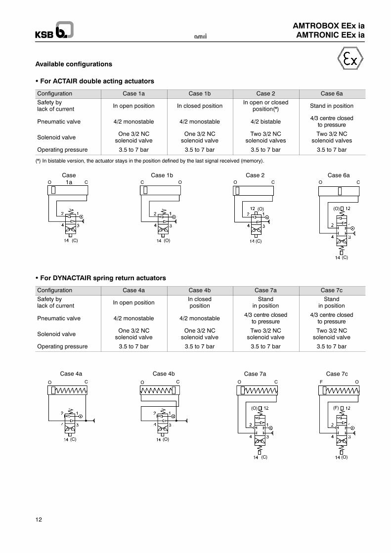
Available configurations
For ACTAIR double acting actuators
Configuration Case 1a Case 1b Case 2 Case 6a
Safety bylack of current In open position In closed position
In open or closedposition(*) Stand in position
Pneumatic valve 4/2 monostable 4/2 monostable 4/2 bistable4/3 centre closed
to pressure
Solenoid valveOne 3/2 NCsolenoid valve
One 3/2 NCsolenoid valve
Two 3/2 NCsolenoid valves
Two 3/2 NCsolenoid valves
Operating pressure 3.5 to 7 bar 3.5 to 7 bar 3.5 to 7 bar 3.5 to 7 bar
(*) In bistable version, the actuator stays in the position defined by the last signal received (memory).
Case1aO C
(C)
Case 1bC O
Case 2O C
(C)
(O)
Case 6aO C
(C)
(O)
(O)
For DYNACTAIR spring return actuators
Configuration Case 4a Case 4b Case 7a Case 7c
Safety bylack of current In open position
In closedposition
Standin position
Standin position
Pneumatic valve 4/2 monostable 4/2 monostable4/3 centre closed
to pressure4/3 centre closed
to pressure
Solenoid valveOne 3/2 NCsolenoid valve
One 3/2 NCsolenoid valve
Two 3/2 NCsolenoid valve
Two 3/2 NCsolenoid valve
Operating pressure 3.5 to 7 bar 3.5 to 7 bar 3.5 to 7 bar 3.5 to 7 bar
Case 4aO C
(C)
Case 4bO C
(O)
Case 7aO C
(C)
(O)
Case 7cOF
(F)
(O)
AMTROBOX EEx iaAMTRONIC EEx ia
13
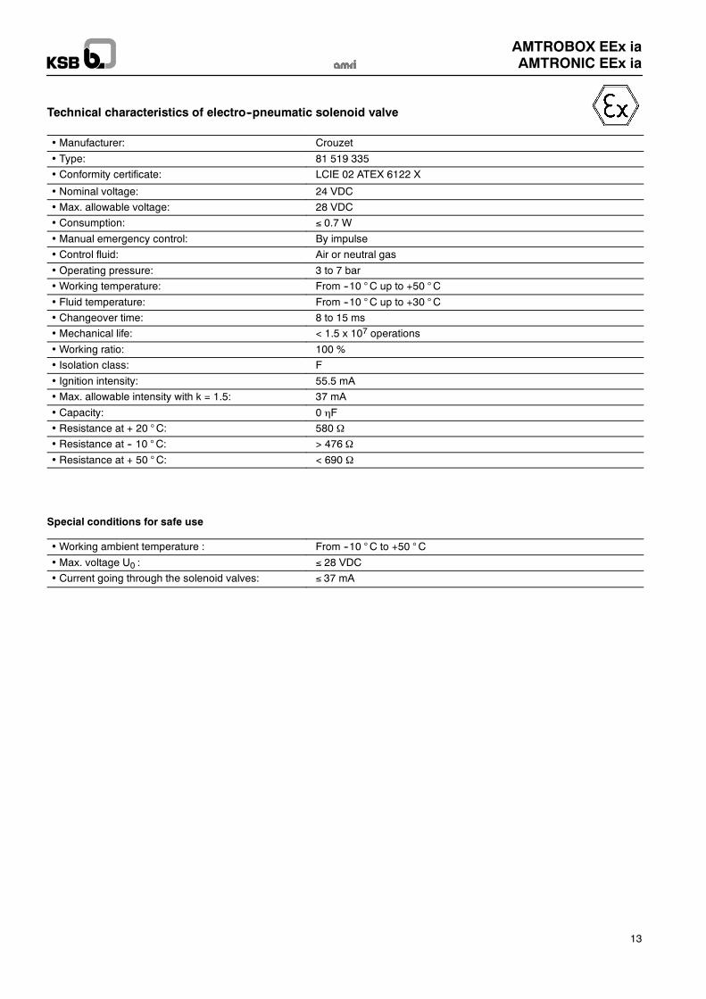
Technical characteristics of electro--pneumatic solenoid valve
Manufacturer: Crouzet
Type: 81 519 335
Conformity certificate: LCIE 02 ATEX 6122 X
Nominal voltage: 24 VDC
Max. allowable voltage: 28 VDC
Consumption: 0.7 W
Manual emergency control: By impulse
Control fluid: Air or neutral gas
Operating pressure: 3 to 7 bar
Working temperature: From --10 °C up to +50 °C
Fluid temperature: From --10 °C up to +30 °C Changeover time: 8 to 15 ms
Mechanical life: < 1.5 x 10⁷ operations
Working ratio: 100 %
Isolation class: F
Ignition intensity: 55.5 mA
Max. allowable intensity with k = 1.5: 37 mA
Capacity: 0 F
Resistance at + 20 °C: 580
Resistance at -- 10 °C: > 476
Resistance at + 50 °C: < 690
Special conditions for safe use
Working ambient temperature : From --10 °C to +50 °C
Max. voltage U0 : 28 VDC
Current going through the solenoid valves: 37 mA
AMTROBOX EEx iaAMTRONIC EEx ia
14
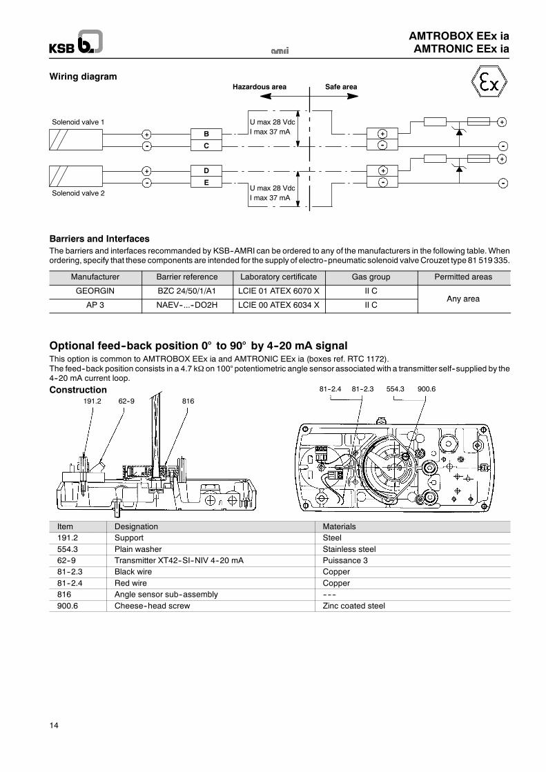
Wiring diagram
+
--
B
C
+
--
D
E
+
+
--
--
+
--
+
--
Hazardous area Safe area
Solenoid valve 1
Solenoid valve 2
U max 28 VdcI max 37 mA
U max 28 VdcI max 37 mA
Barriers and InterfacesThe barriers and interfaces recommanded by KSB--AMRI can be ordered to any of the manufacturers in the following table.Whenordering, specify that these components are intended for the supply of electro--pneumatic solenoid valveCrouzet type 81 519 335.
Manufacturer Barrier reference Laboratory certificate Gas group Permitted areas
GEORGIN BZC 24/50/1/A1 LCIE 01 ATEX 6070 X II CAny area
AP 3 NAEV--...--DO2H LCIE 00 ATEX 6034 X II CAny area
Optional feed--back position 0° to 90° by 4--20 mA signalThis option is common to AMTROBOX EEx ia and AMTRONIC EEx ia (boxes ref. RTC 1172).The feed--back position consists in a 4.7 k on 100° potentiometric angle sensor associated with a transmitter self--supplied by the4--20 mA current loop.
191.2 62--9 816
81--2.4 81--2.3 554.3 900.6Construction
Item Designation Materials191.2 Support Steel554.3 Plain washer Stainless steel62--9 Transmitter XT42--SI--NIV 4--20 mA Puissance 381--2.3 Black wire Copper81--2.4 Red wire Copper816 Angle sensor sub--assembly ------900.6 Cheese--head screw Zinc coated steel
AMTROBOX EEx iaAMTRONIC EEx ia
15
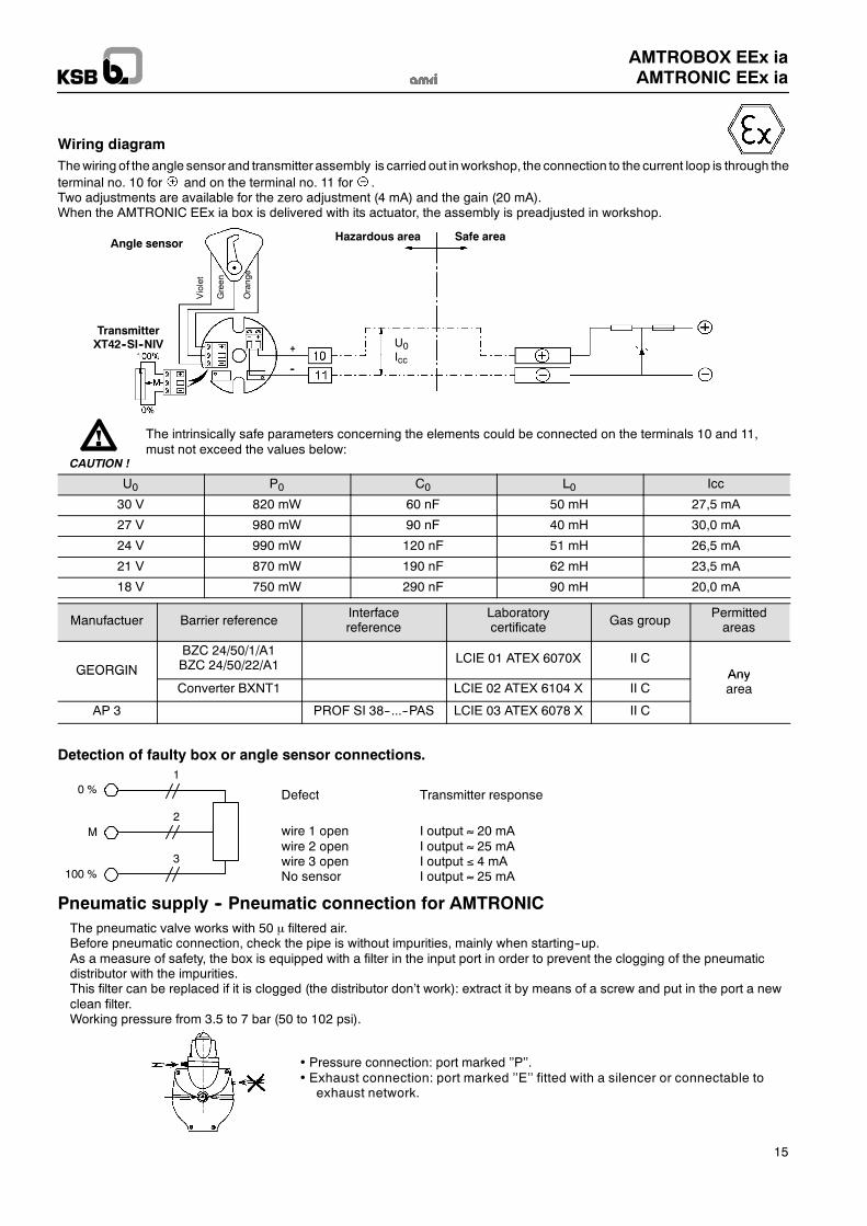
Wiring diagramThewiring of the angle sensor and transmitter assembly is carried out inworkshop, the connection to the current loop is through theterminal no. 10 for and on the terminal no. 11 for .Two adjustments are available for the zero adjustment (4 mA) and the gain (20 mA).When the AMTRONIC EEx ia box is delivered with its actuator, the assembly is preadjusted in workshop.
Orange
Green
Violet
Angle sensor
TransmitterXT42--SI--NIV
Hazardous area Safe area
+
--
U0Icc
The intrinsically safe parameters concerning the elements could be connected on the terminals 10 and 11,must not exceed the values below:
CAUTION !
U0 P0 C0 L0 Icc
30 V 820 mW 60 nF 50 mH 27,5 mA
27 V 980 mW 90 nF 40 mH 30,0 mA
24 V 990 mW 120 nF 51 mH 26,5 mA
21 V 870 mW 190 nF 62 mH 23,5 mA
18 V 750 mW 290 nF 90 mH 20,0 mA
Manufactuer Barrier referenceInterfacereference
Laboratorycertificate Gas group
Permittedareas
GEORGIN
BZC 24/50/1/A1BZC 24/50/22/A1 LCIE 01 ATEX 6070X II C
AnyGEORGINConverter BXNT1 LCIE 02 ATEX 6104 X II C
Anyarea
AP 3 PROF SI 38--...--PAS LCIE 03 ATEX 6078 X II C
Detection of faulty box or angle sensor connections.
0 %
100 %
M
1
2
3
Defect Transmitter response
wire 1 open I output 20 mAwire 2 open I output 25 mAwire 3 open I output 4 mANo sensor I output 25 mA
Pneumatic supply -- Pneumatic connection for AMTRONICThe pneumatic valve works with 50 filtered air.Before pneumatic connection, check the pipe is without impurities, mainly when starting--up.As a measure of safety, the box is equipped with a filter in the input port in order to prevent the clogging of the pneumaticdistributor with the impurities.This filter can be replaced if it is clogged (the distributor don’t work): extract it by means of a screw and put in the port a newclean filter.Working pressure from 3.5 to 7 bar (50 to 102 psi).
Pressure connection: port marked ’’P’’. Exhaust connection: port marked ’’E’’ fitted with a silencer or connectable to
exhaust network.
AMTROBOX EEx iaAMTRONIC EEx ia
16
Commissioning
The installation and start--up of the electro--pneumatic actuators must be according to the best safety practices andmainly:
Piping:Starting--up of a new installation requires cleaning the piping by air before connection to the actuator. This will remove anyimpurities impossible to eliminate during construction (fillings, flux, paste, PTFE, etc.).As a safety measure, the box is equipped with a filter in the input port to prevent clogging of the air valve by impurities. Thisfilter can be replaced (if clogged, the air valve does not work) by extracting it bymeans of a screwand inserting a newcleanfilter.
Electric wiring:-- The electric components are “CE” marked in accordance with 94/9/EC and 2004/108/EC european directive.-- The electric supply voltage and the electric values of the signals must be checked before connecting the components.-- The components of the intrinsically safe electric loops should be checked to ensure the inputs and outputs as well aswiring, do meet the regulations in force.KSB--AMRI shall keep at the disposition of users the loop calculations for the recommended associated equipment.
-- An external earth terminal allows grounding of the metal parts of the control box.
Never exceed the values stipulated in this leaflet!This box is a pressurized electric device. As such, it may be a source of danger for property or even personnel.Any excess of these values may cause damage.
Never uncouple or disassemble the AMTRONIC EEx ia box or its accessories when pressurized or energized.Always make sure that the actuator chambers are free from air pressure by pushing on the buttons for emergency controlof the pilots before disassembling the pneumatic valve, solenoid valvesor the box itself.
Also, always check that the fieldbus wires are disconnected before carrying out any disassembly.
During the mounting and dismantling of the boxes, take care the correct installation of all sealing gaskets. Quality andintegrity depends of this correct installation.
During workshop or on- site checking, the valve associated with the actuator and its AMTRONIC EEx ia box canbe operated from full open to full closed position.This operation may be of a high significant risk of personnal injury if the safety steps required are not taken toprevent access between the disc and the seat.
CAUTION !
WARNING
Electric connectionsThe electric connection is obtained via 2 packing--gland PG 13,5 (plastic or stainless steel).Gland capacity: cable external dia. 8 to 13 mm, wiring to be connected to spring terminal max. are 2.5 mm2.The good tightness of the box depends on cable selection and the tightening level of the packing--gland.
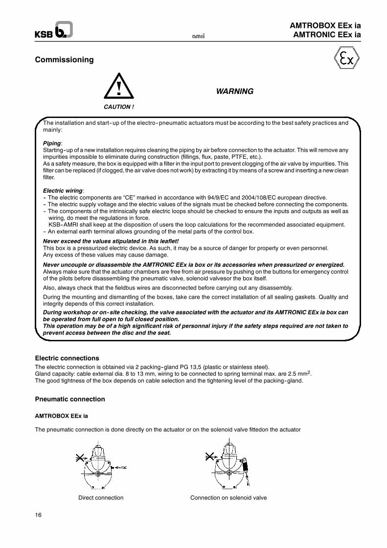
Pneumatic connection
AMTROBOX EEx ia
The pneumatic connection is done directly on the actuator or on the solenoid valve fittedon the actuator
Direct connection Connection on solenoid valve
AMTROBOX EEx iaAMTRONIC EEx ia
17
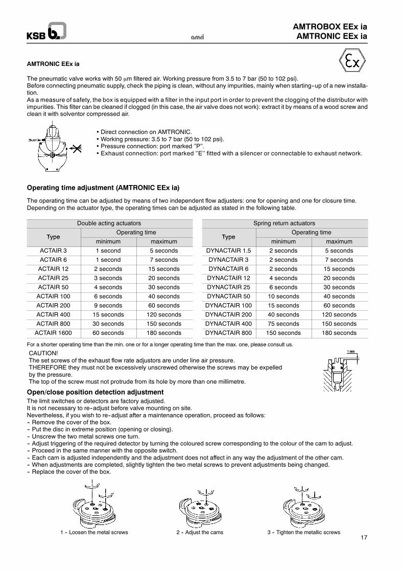
AMTRONIC EEx ia
The pneumatic valve works with 50 m filtered air. Working pressure from 3.5 to 7 bar (50 to 102 psi).Before connecting pneumatic supply, check the piping is clean, without any impurities, mainly when starting--up of a new installa-tion.As a measure of safety, the box is equipped with a filter in the input port in order to prevent the clogging of the distributor withimpurities. This filter can be cleaned if clogged (in this case, the air valve does not work): extract it by means of a wood screw andclean it with solventor compressed air.
Direct connection on AMTRONIC.Working pressure: 3.5 to 7 bar (50 to 102 psi). Pressure connection: port marked ’’P’’. Exhaust connection: port marked ’’E’’ fitted with a silencer or connectable to exhaust network.
Operating time adjustment (AMTRONIC EEx ia)
The operating time can be adjusted by means of two independent flow adjusters: one for opening and one for closure time.Depending on the actuator type, the operating times can be adjusted as stated in the following table.
Double acting actuators
TypeOperating time
Typeminimum maximum
ACTAIR 3 1 second 5 seconds
ACTAIR 6 1 second 7 seconds
ACTAIR 12 2 seconds 15 seconds
ACTAIR 25 3 seconds 20 seconds
ACTAIR 50 4 seconds 30 seconds
ACTAIR 100 6 seconds 40 seconds
ACTAIR 200 9 seconds 60 seconds
ACTAIR 400 15 seconds 120 seconds
ACTAIR 800 30 seconds 150 seconds
ACTAIR 1600 60 seconds 180 seconds
Spring return actuators
TypeOperating time
Typeminimum maximum
DYNACTAIR 1.5 2 seconds 5 seconds
DYNACTAIR 3 2 seconds 7 seconds
DYNACTAIR 6 2 seconds 15 seconds
DYNACTAIR 12 4 seconds 20 seconds
DYNACTAIR 25 6 seconds 30 seconds
DYNACTAIR 50 10 seconds 40 seconds
DYNACTAIR 100 15 seconds 60 seconds
DYNACTAIR 200 40 seconds 120 seconds
DYNACTAIR 400 75 seconds 150 seconds
DYNACTAIR 800 150 seconds 180 seconds
For a shorter operating time than the min. one or for a longer operating time than the max. one, please consult us.
CAUTION!The set screws of the exhaust flow rate adjustors are under line air pressure.THEREFORE they must not be excessively unscrewed otherwise the screws may be expelledby the pressure.The top of the screw must not protrude from its hole by more than one millimetre.
Open/close position detection adjustmentThe limit switches or detectors are factory adjusted.It is not necessary to re--adjust before valve mounting on site.Nevertheless, if you wish to re--adjust after a maintenance operation, proceed as follows:-- Remove the cover of the box.-- Put the disc in extreme position (opening or closing).-- Unscrew the two metal screws one turn.-- Adjust triggering of the required detector by turning the coloured screw corresponding to the colour of the cam to adjust.-- Proceed in the same manner with the opposite switch.-- Each cam is adjusted independently and the adjustment does not affect in any way the adjustment of the other cam.-- When adjustments are completed, slightly tighten the two metal screws to prevent adjustments being changed.-- Replace the cover of the box.
1 -- Loosen the metal screws 2 -- Adjust the cams 3 -- Tighten the metallic screws
AMTROBOX EEx iaAMTRONIC EEx ia
18
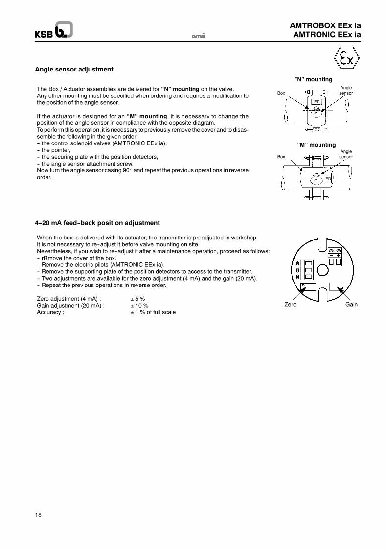
Angle sensor adjustment
’’N’’ mounting
’’M’’ mounting
Box
Box
Anglesensor
Anglesensor
The Box / Actuator assemblies are delivered for “N” mounting on the valve.Any other mounting must be specified when ordering and requires a modification tothe position of the angle sensor.
If the actuator is designed for an “M” mounting, it is necessary to change theposition of the angle sensor in compliance with the opposite diagram.To perform this operation, it is necessary to previously remove the cover and to disas-semble the following in the given order:-- the control solenoid valves (AMTRONIC EEx ia),-- the pointer,-- the securing plate with the position detectors,-- the angle sensor attachment screw.Now turn the angle sensor casing 90° and repeat the previous operations in reverseorder.
ED
ED
4--20 mA feed--back position adjustment
Zero Gain
When the box is delivered with its actuator, the transmitter is preadjusted in workshop.It is not necessary to re--adjust it before valve mounting on site.Nevertheless, if you wish to re--adjust it after a maintenance operation, proceed as follows:-- rRmove the cover of the box.-- Remove the electric pilots (AMTRONIC EEx ia).-- Remove the supporting plate of the position detectors to access to the transmitter.-- Two adjustments are available for the zero adjustment (4 mA) and the gain (20 mA).-- Repeat the previous operations in reverse order.
Zero adjustment (4 mA) : 5 %Gain adjustment (20 mA) : 10 %Accuracy : 1 % of full scale
AMTROBOX EEx iaAMTRONIC EEx ia
19
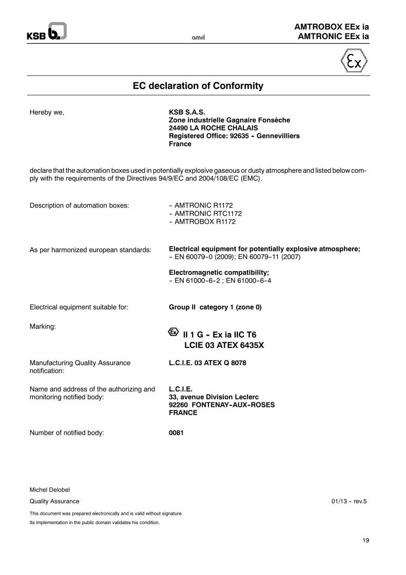
EC declaration of Conformity
Hereby we, KSB S.A.S.Zone industrielle Gagnaire Fonsèche24490 LA ROCHE CHALAISRegistered Office: 92635 -- GennevilliersFrance
declare that theautomationboxes used in potentially explosive gaseous or dusty atmosphereand listedbelowcom-ply with the requirements of the Directives 94/9/EC and 2004/108/EC (EMC).
Description of automation boxes: -- AMTRONIC R1172-- AMTRONIC RTC1172-- AMTROBOX R1172
As per harmonized european standards: Electrical equipment for potentially explosive atmosphere;-- EN 60079--0 (2009); EN 60079--11 (2007)
Electromagnetic compatibility;-- EN 61000--6--2 ; EN 61000--6--4
Electrical equipment suitable for: Group II category 1 (zone 0)
Marking:II 1 G -- Ex ia IIC T6LCIE 03 ATEX 6435X
Manufacturing Quality Assurancenotification:
L.C.I.E. 03 ATEX Q 8078
Name and address of the authorizing andmonitoring notified body:
L.C.I.E.33, avenue Division Leclerc92260 FONTENAY--AUX--ROSESFRANCE
Number of notified body: 0081
Michel Delobel
Quality Assurance 01/13 -- rev.5
This document was prepared electronically and is valid without signature.
Its implementation in the public domain validates his condition.
KSB S.A.S4, allée des Barbanniers 92635 Gennevilliers Cedex (France)Tel.: +33 1 41 47 75 00 Fax: +33 1 41 47 75 10 www.ksb.com
AMTROBOX EEx iaAMTRONIC EEx ia
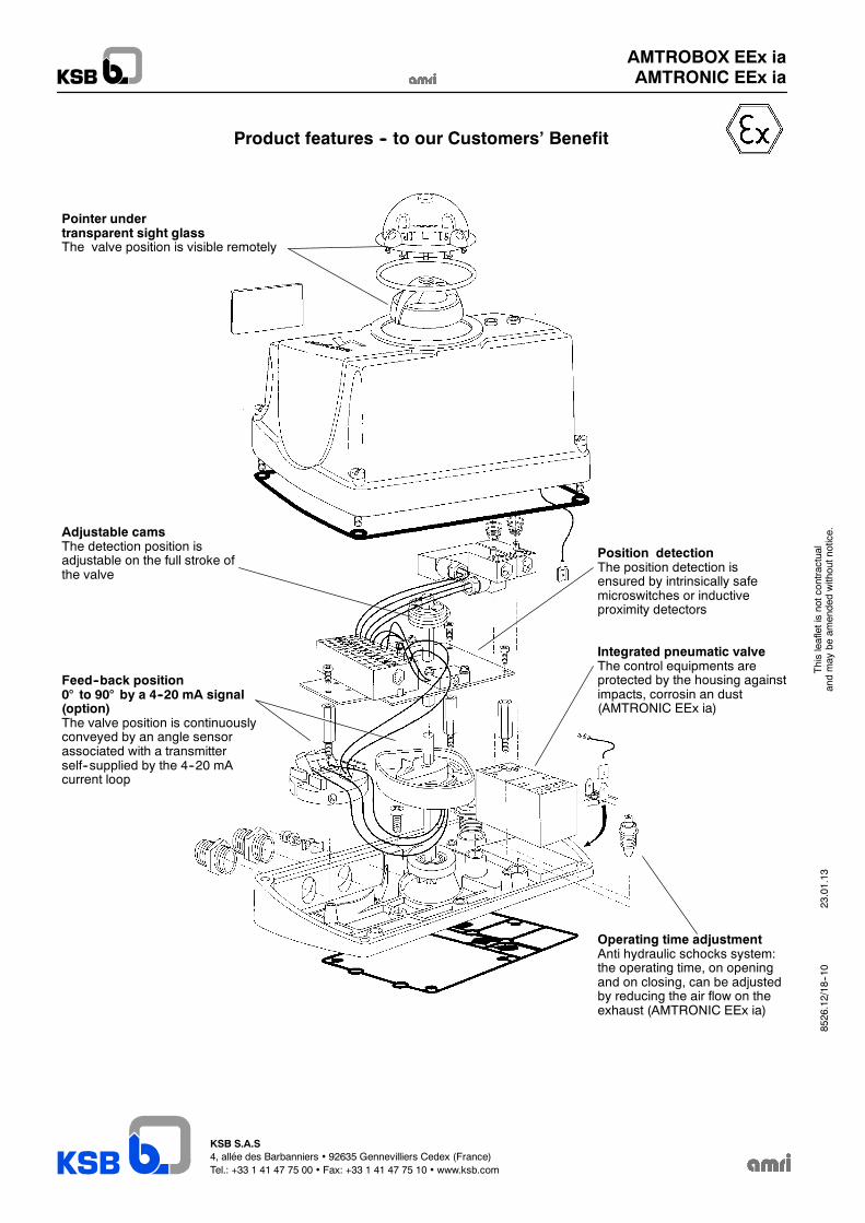
Product features -- to our Customers’ Benefit
Pointer undertransparent sight glassThe valve position is visible remotely
Adjustable camsThe detection position isadjustable on the full stroke ofthe valve
Feed--back position0° to 90° by a 4--20 mA signal(option)The valve position is continuouslyconveyed by an angle sensorassociated with a transmitterself--supplied by the 4--20 mAcurrent loop
Position detectionThe position detection isensured by intrinsically safemicroswitches or inductiveproximity detectors
Integrated pneumatic valveThe control equipments areprotected by the housing againstimpacts, corrosin an dust(AMTRONIC EEx ia)
Operating time adjustmentAnti hydraulic schocks system:the operating time, on openingand on closing, can be adjustedby reducing the air flow on theexhaust (AMTRONIC EEx ia)
23.01.13
Thisleafletisnotcontractual
andmay
beam
endedwithoutnotice.
8526.12/18--10
![EEx d, EEx de, EEX e, Ex nA, Ex N, EEx nA, DIP · ^eskimi i \lektrotehni^eskimi standartami, a takve soglasno sledu@]im ewropejskim normam: ... 1 Klass 2 ili EEx d, EEx de ,EEx e](https://img.pdfslide.net/doc/110x75/5ac92e3a7f8b9a40728d5c17/eex-d-eex-de-eex-e-ex-na-ex-n-eex-na-dip-eskimi-i-lektrotehnieskimi-standartami.jpg)


![GUB zone 2 EEx d IIC EEx d [ia] IIC II2(1)G II2(1)GD -20°C zone 1 zone 2 EEx d IIC EEx d [ia] IIC II2(1)G II2(1)GD-20 C İRTİBAT KUTUSU - ENCLOSURE T6 T4T5 EEx de IIC II2G II2GD](https://img.pdfslide.net/doc/110x75/5adfd2567f8b9ad66b8d5f4a/gub-zone-2-eex-d-iic-eex-d-ia-iic-ii21g-ii21gd-zone-1-zone-2-eex-d-iic-eex.jpg)


![Ppt eex[1]](https://img.pdfslide.net/doc/110x75/547b4f55b4af9fc9158b4e38/ppt-eex1.jpg)