Embed Size (px)
Citation preview
11
An Efficient Method for Improving An Efficient Method for Improving Coherence of Multiple Aperture Coherence of Multiple Aperture
InterferogramInterferogram (MAI)(MAI)
HyungHyung--Sup JungSup Jung, Chang-Wook Lee, San-Wan Kim,Van Trung Nguyen and Joong-Sun Won
22
Contents • Introduction– Estimation of along-track deformation
using MAI• Objectives• Methodology
– Range-Doppler Processing for MAI– Optimal procedure for MAI
• Results• Conclusions
33
Introduction• DInSAR technique
– Estimation of centimeter-scale surface deformation along the satellite’s LOS direction
– Measurement of the along-track deformation : • Amplitude pixel offset method
– Using cross correlation of two or more amplitude images
– Although this method has been in fairly wide use, it has very reduced sensitivity
• Multiple aperture interferometric SAR method – By split-beam InSAR processing, to create forward-
and backward- looking interferograms

44
Introduction• MAInSAR method
– Bechor and Zebker (2006)– Forward- and backward-looking
SLC images are generated by • Modifying the Doppler centroid fDC• Limiting the integration time
– Squint angles between forward-and backward- SLC images are slightly different.
• For ERS, about 0.3 deg.
55
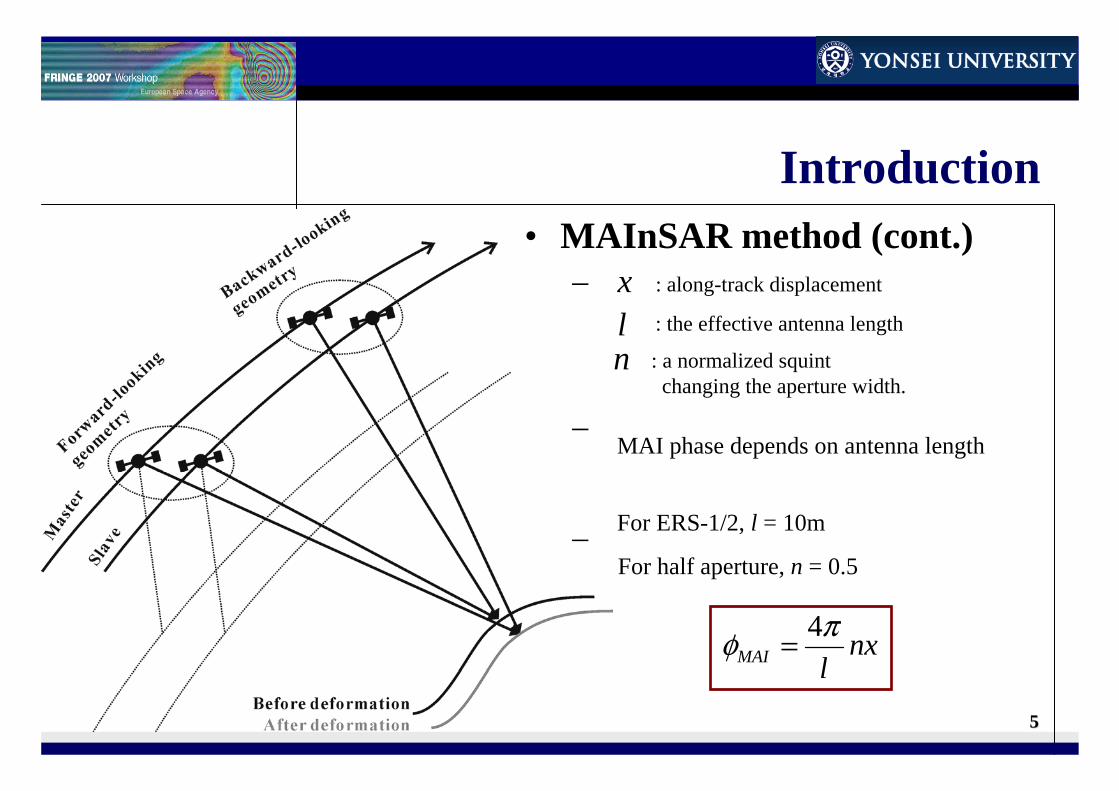
Introduction• MAInSAR method (cont.)
– Forward- and backward-looking interferograms are generated from forward- and backward- SLC interferometric pair, respectively.
– MAI is generated by the phase difference between forward- and backward-looking interferograms.
– MAI phase (Bechor and Zebker, 2006)
nxlMAIπφ 4=
x : along-track displacement
l : the effective antenna length
n : a normalized squint changing the aperture width.
MAI phase depends on antenna length
For ERS-1/2, l = 10m
For half aperture, n = 0.5
66
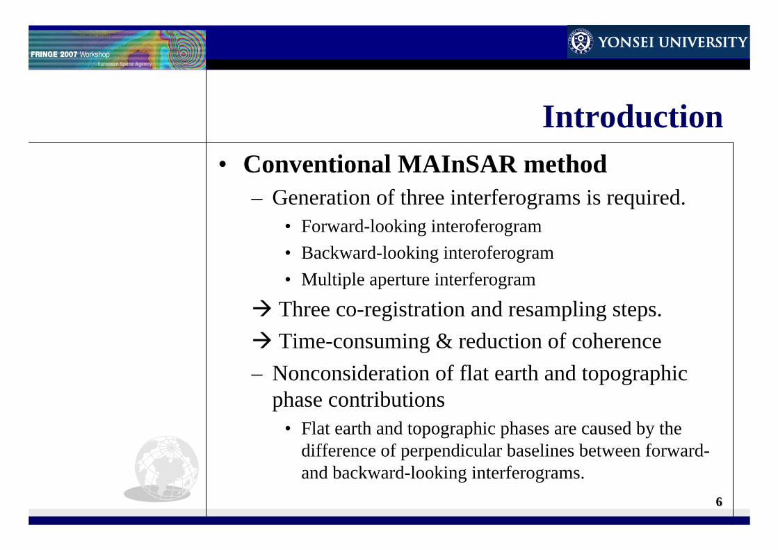
Introduction• Conventional MAInSAR method
– Generation of three interferograms is required.• Forward-looking interoferogram• Backward-looking interoferogram• Multiple aperture interferogram
Three co-registration and resampling steps.Time-consuming & reduction of coherence
– Nonconsideration of flat earth and topographic phase contributions
• Flat earth and topographic phases are caused by the difference of perpendicular baselines between forward-and backward-looking interferograms.
77
Objectives• Improvement of the coherence of MAI &
reduction of processing time– Co-registration of forward- and backward-looking
SLC images using time shift property of Fourier transform without resampling in RD processing.
• Development of optimal procedure for MAInSAR technique– Minimization of flat earth and topographic phase
contributions using forward- and backward-differential interferograms.
88
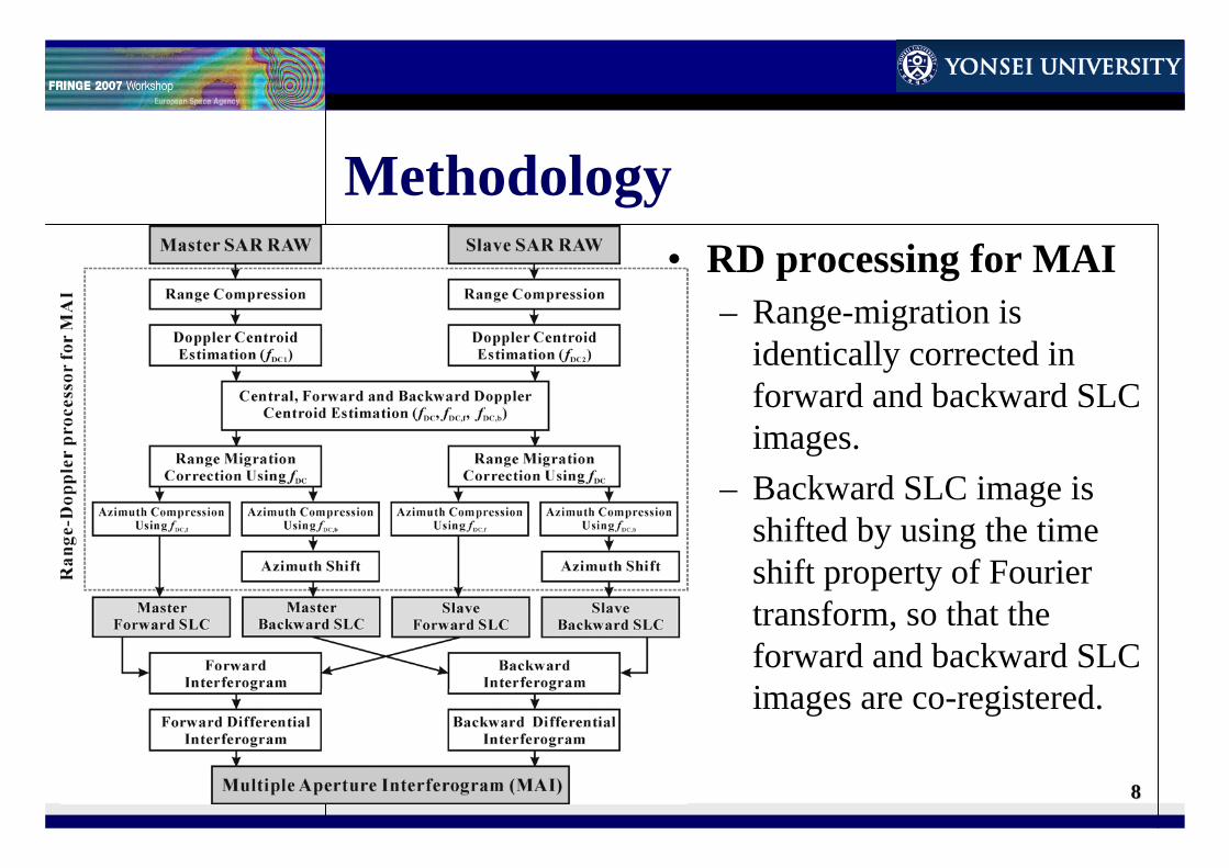
Methodology• RD processing for MAI
– Range-migration is identically corrected in forward and backward SLC images.
– Backward SLC image is shifted by using the time shift property of Fourier transform, so that the forward and backward SLC images are co-registered.
99
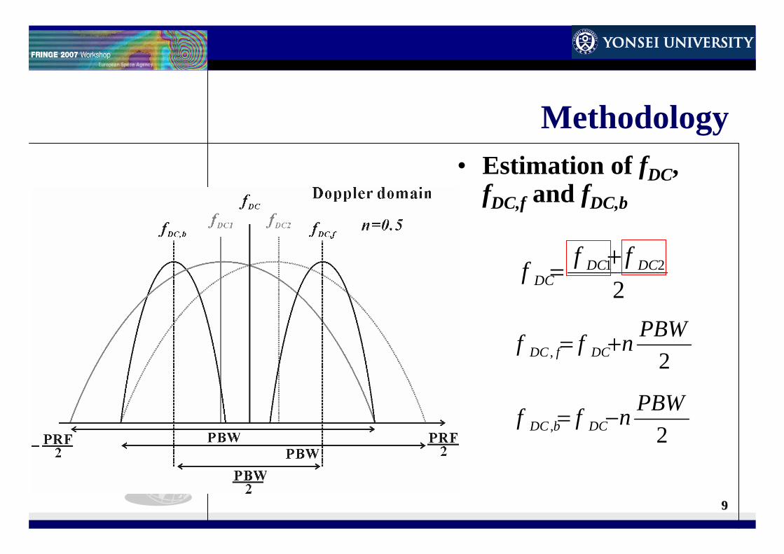
Methodology• Estimation of fDC,
fDC,f and fDC,b
221 DCDC
DCfff +=
2,PBWnff DCfDC +=
2,PBWnff DCbDC −=
1010
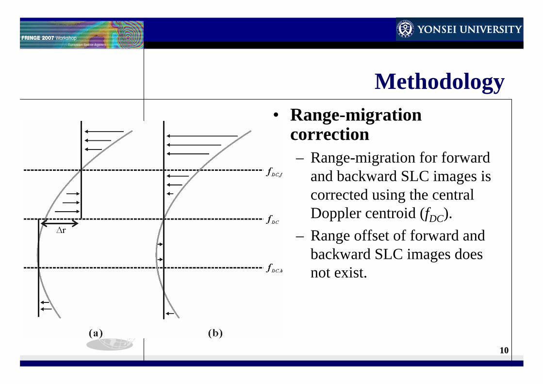
Methodology• Range-migration
correction– Range-migration for forward
and backward SLC images is corrected using the central Doppler centroid (fDC).
– Range offset of forward and backward SLC images does not exist.
1111
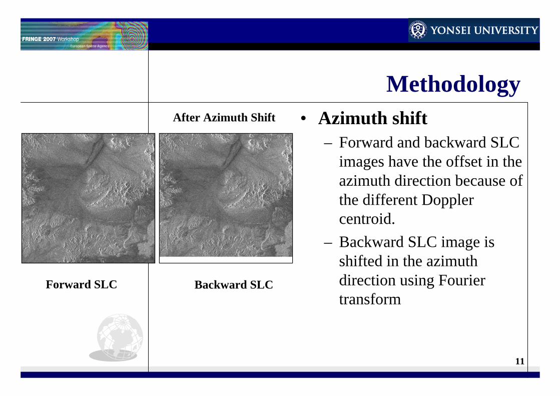
Methodology• Azimuth shift
– Forward and backward SLC images have the offset in the azimuth direction because of the different Doppler centroid.
– Backward SLC image is shifted in the azimuth direction using Fourier transform
Forward SLC Backward SLC
Before azimuth shiftAfter Azimuth Shift

1212
Methodology• Flat earth and topographic
phase contributions– The baselines of forward- and
backward- looking interferograms are slightly different.
– Flat earth and topographic phases are caused by the difference of perpendicular baseline (δB⊥).
1313
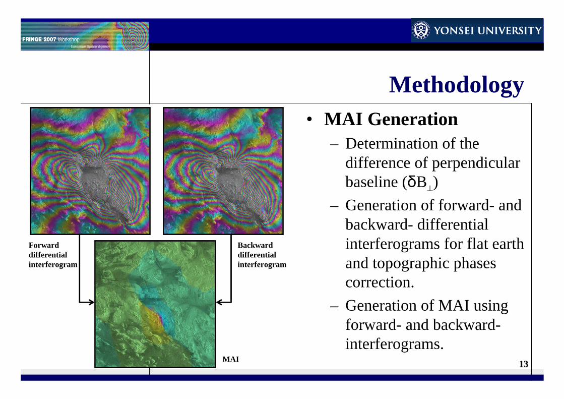
Methodology• MAI Generation
– Determination of the difference of perpendicular baseline (δB⊥)
– Generation of forward- and backward- differential interferograms for flat earth and topographic phases correction.
– Generation of MAI using forward- and backward-interferograms.
Forward differential interferogram
Backward differential interferogram
MAI
1414
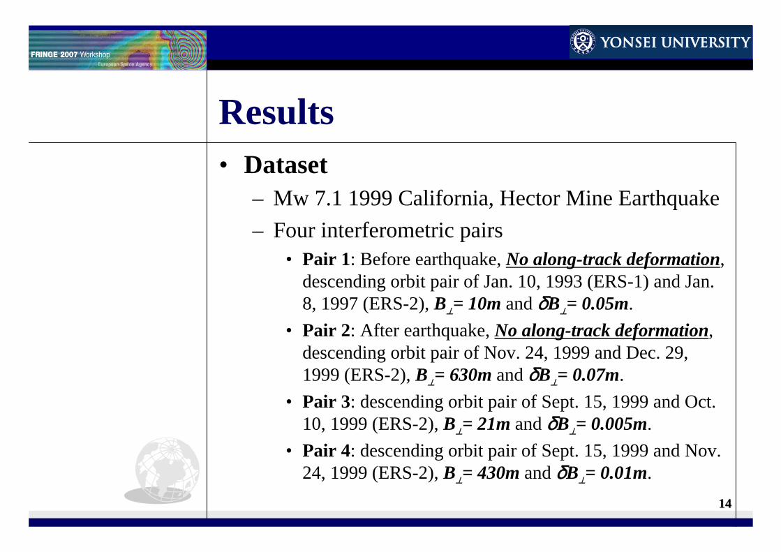
Results• Dataset
– Mw 7.1 1999 California, Hector Mine Earthquake– Four interferometric pairs
• Pair 1: Before earthquake, No along-track deformation, descending orbit pair of Jan. 10, 1993 (ERS-1) and Jan. 8, 1997 (ERS-2), B⊥= 10m and δB⊥= 0.05m.
• Pair 2: After earthquake, No along-track deformation, descending orbit pair of Nov. 24, 1999 and Dec. 29, 1999 (ERS-2), B⊥= 630m and δB⊥= 0.07m.
• Pair 3: descending orbit pair of Sept. 15, 1999 and Oct. 10, 1999 (ERS-2), B⊥= 21m and δB⊥= 0.005m.
• Pair 4: descending orbit pair of Sept. 15, 1999 and Nov. 24, 1999 (ERS-2), B⊥= 430m and δB⊥= 0.01m.
1515
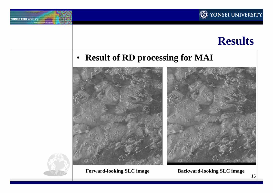
Results• Result of RD processing for MAI
Forward-looking SLC image Backward-looking SLC image
1616
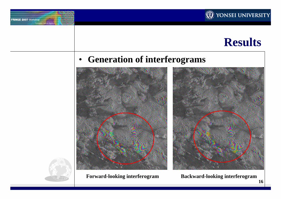
Results• Generation of interferograms
Forward-looking interferogram Backward-looking interferogram
1717
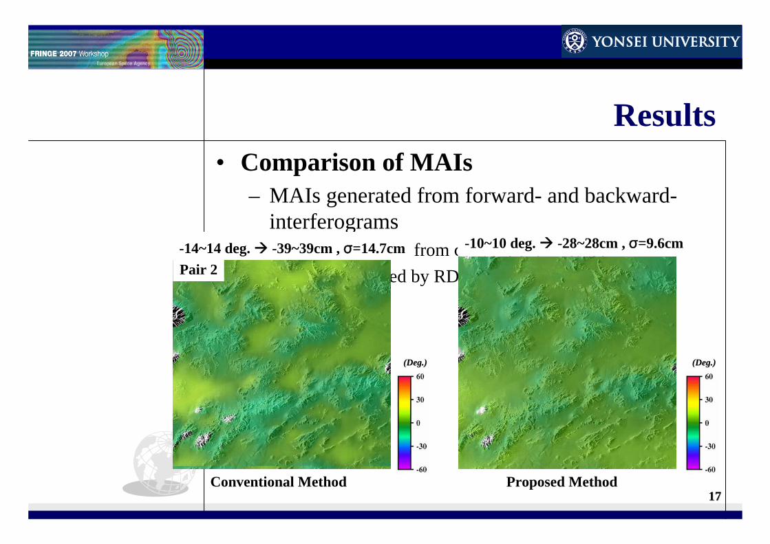
Results• Comparison of MAIs
– MAIs generated from forward- and backward-interferograms
• MAI generated from conventional method• MAI produced by RD processing for MAI
Conventional Method Proposed Method
(Deg.)(Deg.) (Deg.)(Deg.)
Pair 1
-12~12 deg. -33~33cm , σ=12.3cm -8~8 deg. -22~22cm, σ=7.5cm
Pair 2-14~14 deg. -39~39cm , σ=14.7cm -10~10 deg. -28~28cm , σ=9.6cm
1818
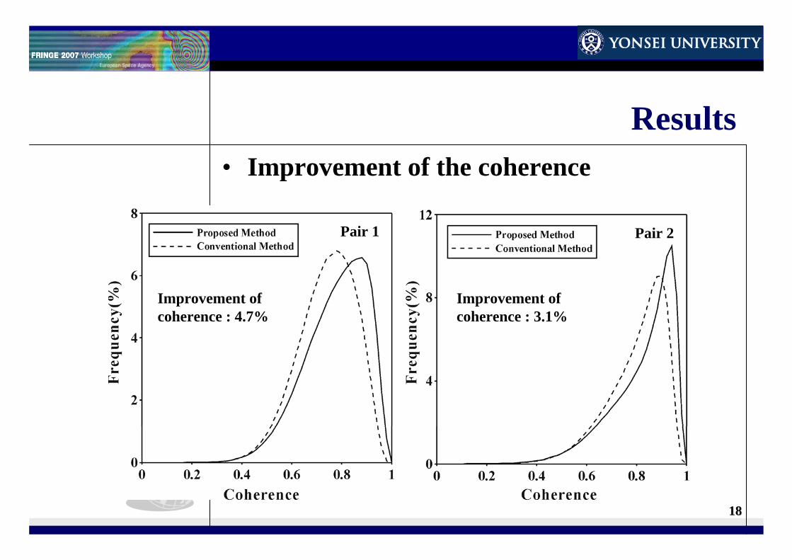
Results• Improvement of the coherence
Pair 1 Pair 2
Improvement of coherence : 4.7%
Improvement of coherence : 3.1%
1919
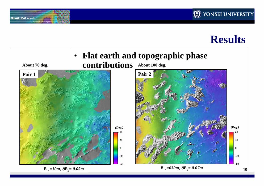
Results• Flat earth and topographic phase
contributions
B ⊥ =10m, δB⊥= 0.05m
(Deg.)(Deg.)
Pair 1Pair 1
B ⊥ =630m, δB⊥= 0.07m
(Deg.)(Deg.)
Pair 2Pair 2
About 70 deg. About 100 deg.
2020
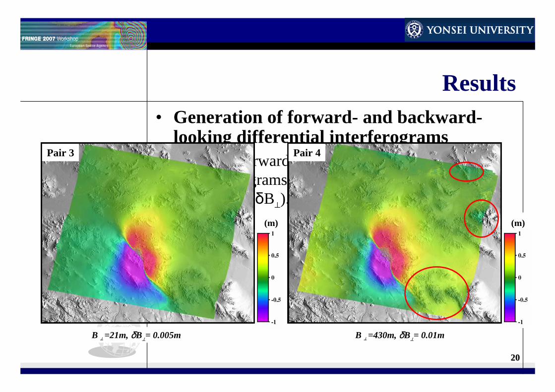
Results• Generation of forward- and backward-
looking differential interferograms– Using Forward- and backward- differential
interferograms difference of perpendicular baseline (δB⊥).
(m)
Pair 3
B ⊥ =21m, δB⊥= 0.005m
(m)
Pair 4
B ⊥ =430m, δB⊥= 0.01m
(m) (m)
Pair 3 Pair 4

2121
Conclusions• Improvement of the coherence
– Coherence of MAI is improved about 4 percents by the proposed RD processing.
• Reduction of processing time– Two co-registration and one resampling steps are
reduced.• Removal of Flat earth and topographic
phase contributions– Flat earth and topographic phases are removed
from forward- and backward- differential interterferograms using the difference of their perpendicular baselines.
2222
Thank you for your attentionThank you for your attention
2323
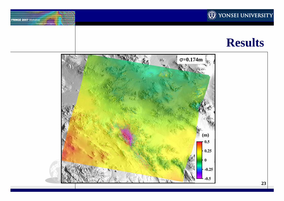
Results
(m)
σ=0.174m
2424
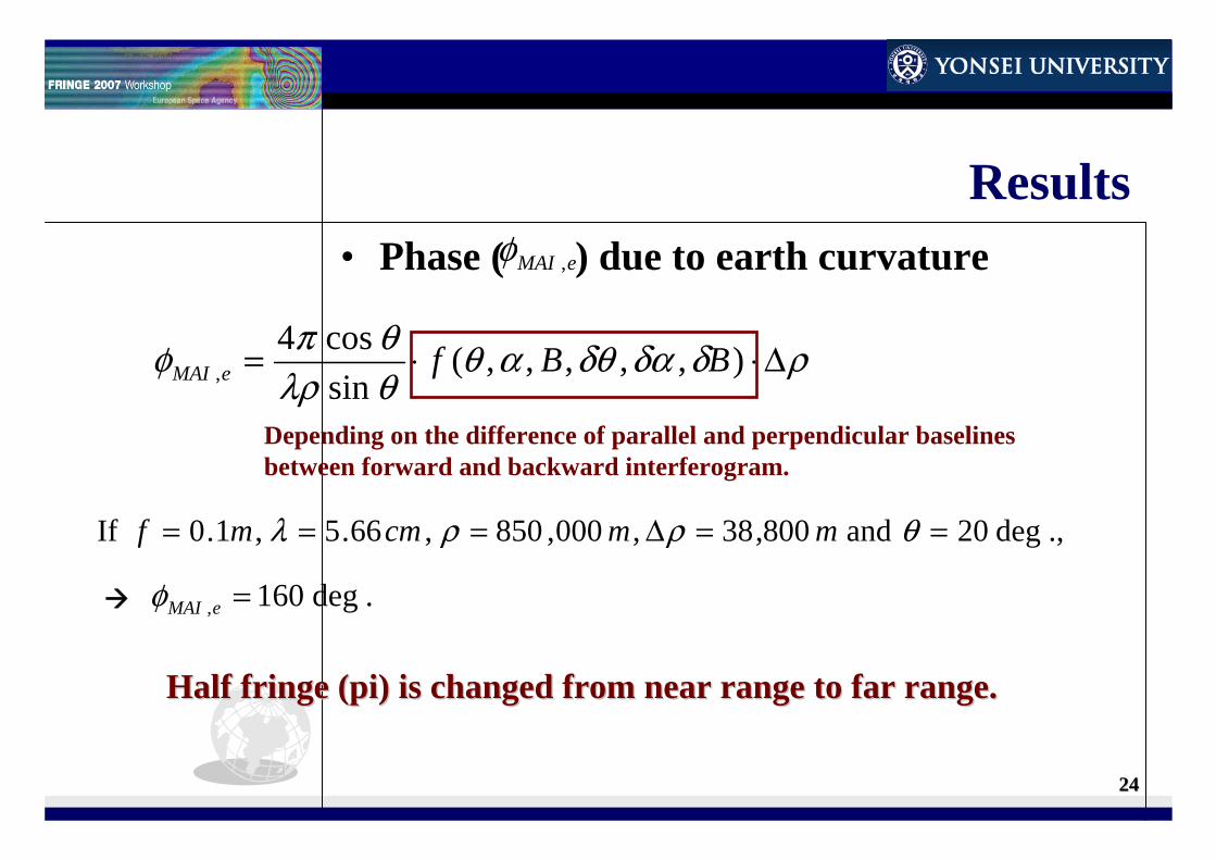
Results• Phase ( ) due to earth curvature
ρδδαδθαθθλρθπφ Δ⋅⋅= ),,,,,(
sincos4
, BBfeMAI
Depending on the difference of parallel and perpendicular baselines between forward and backward interferogram.
.,deg20 and 800,38,000,850 ,66.5 ,1.0 If ==Δ=== θρρλ mmcmmf
.deg160, =eMAIφ
Half fringe (pi) is changed from near range to far range.Half fringe (pi) is changed from near range to far range.
eMAI ,φ
2525
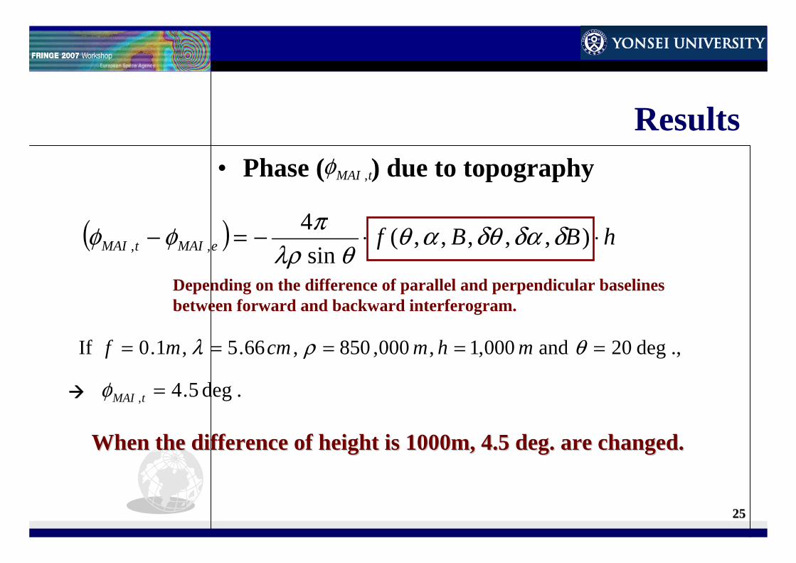
Results• Phase ( ) due to topography
Depending on the difference of parallel and perpendicular baselines between forward and backward interferogram.
.,deg20 and 000,1,000,850 ,66.5 ,1.0 If ===== θρλ mhmcmmf
.deg5.4, =tMAIφ
When the difference of height is 1000m, 4.5 deg. are changed.When the difference of height is 1000m, 4.5 deg. are changed.
( ) hBBfeMAItMAI ⋅⋅−=− ),,,,,(sin
4,, δδαδθαθ
θλρπφφ
tMAI ,φ