Embed Size (px)
Citation preview
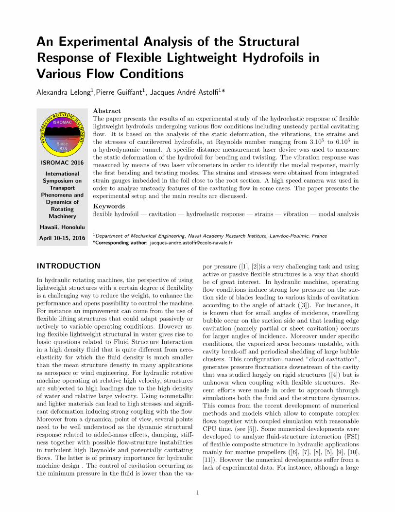
An Experimental Analysis of the StructuralResponse of Flexible Lightweight Hydrofoils inVarious Flow ConditionsAlexandra Lelong1,Pierre Guiffant1, Jacques Andre Astolfi1*
SYM
POSI
A
ON ROTATING MACHIN
ERY
ISROMAC 2016
InternationalSymposium on
TransportPhenomena and
Dynamics ofRotating
Machinery
Hawaii, Honolulu
April 10-15, 2016
AbstractThe paper presents the results of an experimental study of the hydroelastic response of flexiblelightweight hydrofoils undergoing various flow conditions including unsteady partial cavitatingflow. It is based on the analysis of the static deformation, the vibrations, the strains andthe stresses of cantilevered hydrofoils, at Reynolds number ranging from 3.105 to 6.105 ina hydrodynamic tunnel. A specific distance measurement laser device was used to measurethe static deformation of the hydrofoil for bending and twisting. The vibration response wasmeasured by means of two laser vibrometers in order to identify the modal response, mainlythe first bending and twisting modes. The strains and stresses were obtained from integratedstrain gauges imbedded in the foil close to the root section. A high speed camera was used inorder to analyze unsteady features of the cavitating flow in some cases. The paper presents theexperimental setup and the main results are discussed.
Keywordsflexible hydrofoil — cavitation — hydroelastic response — strains — vibration — modal analysis
1Department of Mechanical Engineering, Naval Academy Research Institute, Lanveoc-Poulmic, France
*Corresponding author: [email protected]
INTRODUCTION
In hydraulic rotating machines, the perspective of usinglightweight structures with a certain degree of flexibilityis a challenging way to reduce the weight, to enhance theperformance and opens possibility to control the machine.For instance an improvement can come from the use offlexible lifting structures that could adapt passively oractively to variable operating conditions. However us-ing flexible lightweight structural in water gives rise tobasic questions related to Fluid Structure Interactionin a high density fluid that is quite different from aero-elasticity for which the fluid density is much smallerthan the mean structure density in many applicationsas aerospace or wind engineering. For hydraulic rotativemachine operating at relative high velocity, structuresare subjected to high loadings due to the high densityof water and relative large velocity. Using nonmetallicand lighter materials can lead to high stresses and signifi-cant deformation inducing strong coupling with the flow.Moreover from a dynamical point of view, several pointsneed to be well understood as the dynamic structuralresponse related to added-mass effects, damping, stiff-ness together with possible flow-structure instabilitiesin turbulent high Reynolds and potentially cavitatingflows. The latter is of primary importance for hydraulicmachine design . The control of cavitation occurring asthe minimum pressure in the fluid is lower than the va-
por pressure ([1], [2])is a very challenging task and usingactive or passive flexible structures is a way that shouldbe of great interest. In hydraulic machine, operatingflow conditions induce strong low pressure on the suc-tion side of blades leading to various kinds of cavitationaccording to the angle of attack ([3]). For instance, itis known that for small angles of incidence, travellingbubble occur on the suction side and that leading edgecavitation (namely partial or sheet cavitation) occursfor larger angles of incidence. Moreover under specificconditions, the vaporized area becomes unstable, withcavity break-off and periodical shedding of large bubbleclusters. This configuration, named ”cloud cavitation”,generates pressure fluctuations downstream of the cavitythat was studied largely on rigid structures ([4]) but isunknown when coupling with flexible structures. Re-cent efforts were made in order to approach throughsimulations both the fluid and the structure dynamics.This comes from the recent development of numericalmethods and models which allow to compute complexflows together with coupled simulation with reasonableCPU time, (see [5]). Some numerical developments weredeveloped to analyze fluid-structure interaction (FSI)of flexible composite structure in hydraulic applicationsmainly for marine propellers ([6], [7], [8], [5], [9], [10],[11]). However the numerical developments suffer from alack of experimental data. For instance, although a large
1
An Experimental Analysis of the Structural Response of Flexible Lightweight Hydrofoils in Various Flow Conditions — 2/9
number of experimental studies deals with the analysisof cavitation over rigid hydrofoils ([4],[12]) little referredto experimental cavitation on flexible structures. Au-soni at al. ([13]) studied experimentally the vibrationresponse of a metallic hydrofoil but only recently, cavita-tion over a flexible hydrofoil has been studied numericallyand experimentally ([14], [15], [16],[17], [18] and [19]) ortheoretically ([20], [21]). Theses studies deal with thevibration induced by the cavitation on a 3D hydrofoil ora two degrees of freedom model of a rigid hydrofoil inpitching and heaving motion. They indicated that cavita-tion can change the modal response of the structure andthat a lock-in of the foil’s frequencies in cavitating flowscan occur in specific conditions but that experimentaldata and physical observations are still required for abetter understanding of a complex FSI phenomena to bebeneficial for simulation of FSI in hydraulic applications.
The present paper deals with a collaborative researchprogram between the French Naval Academy and theDepartment of Naval Architecture and Marine Engineer-ing at the University of Michigan in order to analyze thehydroelastic response of a flexible homogeneous hydrofoilin various flow conditions including cavitating flow. Theobjective of the program is to perform physical analysisas well as to improve simulations of FSI for heavy fluidapplications.
1. EXPERIMENTAL SETUP
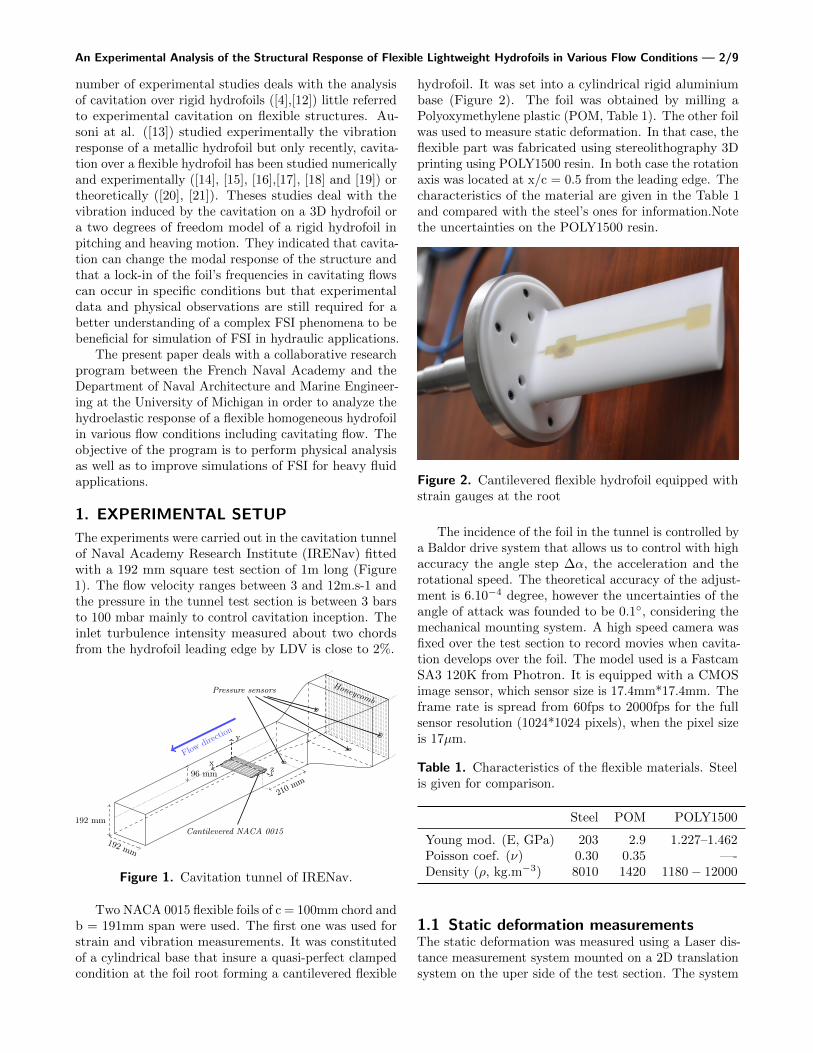
The experiments were carried out in the cavitation tunnelof Naval Academy Research Institute (IRENav) fittedwith a 192 mm square test section of 1m long (Figure1). The flow velocity ranges between 3 and 12m.s-1 andthe pressure in the tunnel test section is between 3 barsto 100 mbar mainly to control cavitation inception. Theinlet turbulence intensity measured about two chordsfrom the hydrofoil leading edge by LDV is close to 2%.
x
y
z
Honeycomb
Flowdire
ction
210mm
192 mm
192 mm
96 mm
Cantilevered NACA 0015
Pressure sensors
Figure 1. Cavitation tunnel of IRENav.
Two NACA 0015 flexible foils of c = 100mm chord andb = 191mm span were used. The first one was used forstrain and vibration measurements. It was constitutedof a cylindrical base that insure a quasi-perfect clampedcondition at the foil root forming a cantilevered flexible
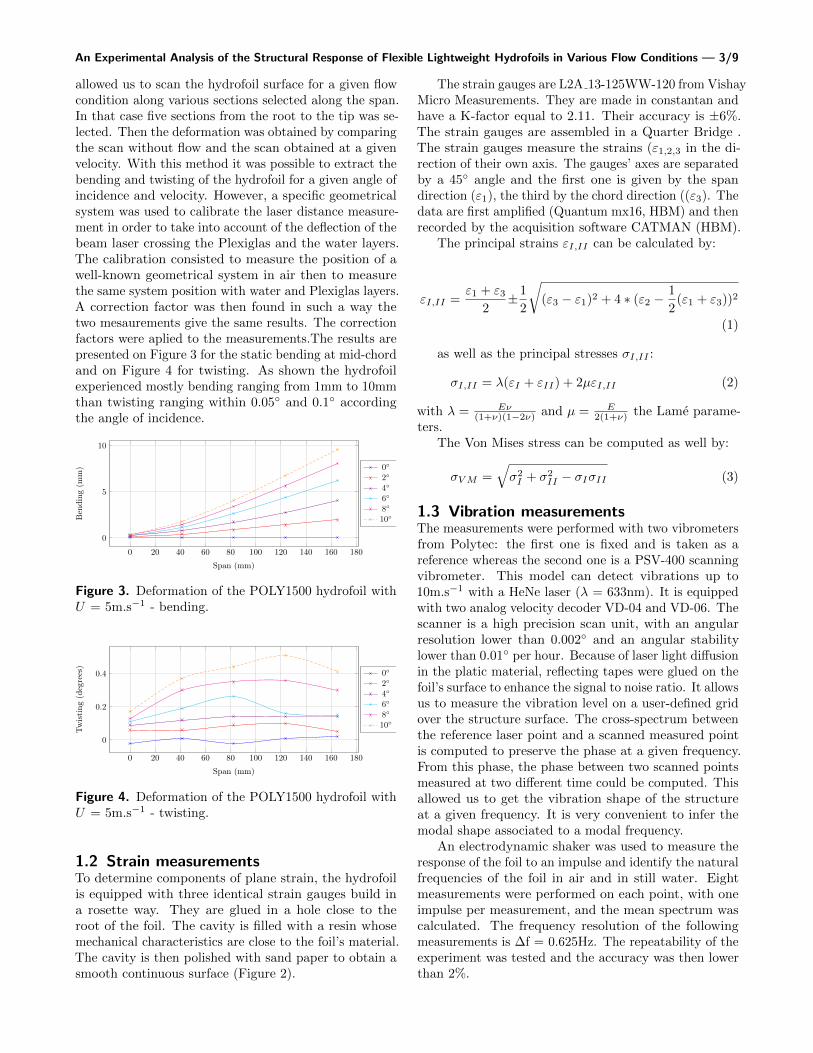
hydrofoil. It was set into a cylindrical rigid aluminiumbase (Figure 2). The foil was obtained by milling aPolyoxymethylene plastic (POM, Table 1). The other foilwas used to measure static deformation. In that case, theflexible part was fabricated using stereolithography 3Dprinting using POLY1500 resin. In both case the rotationaxis was located at x/c = 0.5 from the leading edge. Thecharacteristics of the material are given in the Table 1and compared with the steel’s ones for information.Notethe uncertainties on the POLY1500 resin.
Figure 2. Cantilevered flexible hydrofoil equipped withstrain gauges at the root
The incidence of the foil in the tunnel is controlled bya Baldor drive system that allows us to control with highaccuracy the angle step ∆α, the acceleration and therotational speed. The theoretical accuracy of the adjust-ment is 6.10−4 degree, however the uncertainties of theangle of attack was founded to be 0.1◦, considering themechanical mounting system. A high speed camera wasfixed over the test section to record movies when cavita-tion develops over the foil. The model used is a FastcamSA3 120K from Photron. It is equipped with a CMOSimage sensor, which sensor size is 17.4mm*17.4mm. Theframe rate is spread from 60fps to 2000fps for the fullsensor resolution (1024*1024 pixels), when the pixel sizeis 17µm.
Table 1. Characteristics of the flexible materials. Steelis given for comparison.
Steel POM POLY1500
Young mod. (E, GPa) 203 2.9 1.227–1.462Poisson coef. (ν) 0.30 0.35 —-Density (ρ, kg.m−3) 8010 1420 1180 − 12000
1.1 Static deformation measurementsThe static deformation was measured using a Laser dis-tance measurement system mounted on a 2D translationsystem on the uper side of the test section. The system
An Experimental Analysis of the Structural Response of Flexible Lightweight Hydrofoils in Various Flow Conditions — 3/9
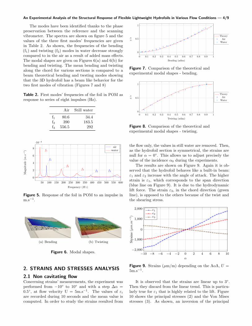
allowed us to scan the hydrofoil surface for a given flowcondition along various sections selected along the span.In that case five sections from the root to the tip was se-lected. Then the deformation was obtained by comparingthe scan without flow and the scan obtained at a givenvelocity. With this method it was possible to extract thebending and twisting of the hydrofoil for a given angle ofincidence and velocity. However, a specific geometricalsystem was used to calibrate the laser distance measure-ment in order to take into account of the deflection of thebeam laser crossing the Plexiglas and the water layers.The calibration consisted to measure the position of awell-known geometrical system in air then to measurethe same system position with water and Plexiglas layers.A correction factor was then found in such a way thetwo mesaurements give the same results. The correctionfactors were aplied to the measurements.The results arepresented on Figure 3 for the static bending at mid-chordand on Figure 4 for twisting. As shown the hydrofoilexperienced mostly bending ranging from 1mm to 10mmthan twisting ranging within 0.05◦ and 0.1◦ accordingthe angle of incidence.
0 20 40 60 80 100 120 140 160 180
0
5
10
Span (mm)
Ben
ding
(mm
) 0◦
2◦
4◦
6◦
8◦
10◦
Figure 3. Deformation of the POLY1500 hydrofoil withU = 5m.s−1 - bending.
0 20 40 60 80 100 120 140 160 180
0
0.2
0.4
Span (mm)
Tw
isti
ng(d
egre
es)
0◦
2◦
4◦
6◦
8◦
10◦
Figure 4. Deformation of the POLY1500 hydrofoil withU = 5m.s−1 - twisting.
1.2 Strain measurementsTo determine components of plane strain, the hydrofoilis equipped with three identical strain gauges build ina rosette way. They are glued in a hole close to theroot of the foil. The cavity is filled with a resin whosemechanical characteristics are close to the foil’s material.The cavity is then polished with sand paper to obtain asmooth continuous surface (Figure 2).
The strain gauges are L2A 13-125WW-120 from VishayMicro Measurements. They are made in constantan andhave a K-factor equal to 2.11. Their accuracy is ±6%.The strain gauges are assembled in a Quarter Bridge .The strain gauges measure the strains (ε1,2,3 in the di-rection of their own axis. The gauges’ axes are separatedby a 45◦ angle and the first one is given by the spandirection (ε1), the third by the chord direction ((ε3). Thedata are first amplified (Quantum mx16, HBM) and thenrecorded by the acquisition software CATMAN (HBM).
The principal strains εI,II can be calculated by:
εI,II =ε1 + ε3
2±1
2
√(ε3 − ε1)2 + 4 ∗ (ε2 −
1
2(ε1 + ε3))2
(1)
as well as the principal stresses σI,II :
σI,II = λ(εI + εII) + 2µεI,II (2)
with λ = Eν(1+ν)(1−2ν) and µ = E
2(1+ν) the Lame parame-ters.
The Von Mises stress can be computed as well by:
σVM =√σ2I + σ2
II − σIσII (3)
1.3 Vibration measurementsThe measurements were performed with two vibrometersfrom Polytec: the first one is fixed and is taken as areference whereas the second one is a PSV-400 scanningvibrometer. This model can detect vibrations up to10m.s−1 with a HeNe laser (λ = 633nm). It is equippedwith two analog velocity decoder VD-04 and VD-06. Thescanner is a high precision scan unit, with an angularresolution lower than 0.002◦ and an angular stabilitylower than 0.01◦ per hour. Because of laser light diffusionin the platic material, reflecting tapes were glued on thefoil’s surface to enhance the signal to noise ratio. It allowsus to measure the vibration level on a user-defined gridover the structure surface. The cross-spectrum betweenthe reference laser point and a scanned measured pointis computed to preserve the phase at a given frequency.From this phase, the phase between two scanned pointsmeasured at two different time could be computed. Thisallowed us to get the vibration shape of the structureat a given frequency. It is very convenient to infer themodal shape associated to a modal frequency.
An electrodynamic shaker was used to measure theresponse of the foil to an impulse and identify the naturalfrequencies of the foil in air and in still water. Eightmeasurements were performed on each point, with oneimpulse per measurement, and the mean spectrum wascalculated. The frequency resolution of the followingmeasurements is ∆f = 0.625Hz. The repeatability of theexperiment was tested and the accuracy was then lowerthan 2%.
An Experimental Analysis of the Structural Response of Flexible Lightweight Hydrofoils in Various Flow Conditions — 4/9
The modes have been identified thanks to the phasepreservation between the reference and the scanningvibrometer. The spectra are shown on figure 5 and thevalues of the three first modes’ frequencies are givenin Table 2. As shown, the frequencies of the bending(f1) and twisting (f2) modes in water decrease stronglycompared to in the air as a result of added mass effects.The modal shapes are given on Figures 6(a) and 6(b) forbending and twisting. The mean bending and twistingalong the chord for various sections is compared to abeam theoretical bending and twsting modes showingthat the 3D hydrofoil has a beam like behavior for thetwo first modes of vibration (Figures 7 and 8)
Table 2. First modes’ frequencies of the foil in POM asresponse to series of eight impulses (Hz).
Air Still water
f1 80.6 34.4f2 390 183.5f3 556.5 292
50 100 150 200 250 300 350 400 450 500 550 600
0
2
4
6
8
·10−4
f1
f2f3
f1
f2 f3
Frequency (Hz)
Mag
nitu
de(m
.s−1)
airwater
Figure 5. Response of the foil in POM to an impulse inm.s−1.
(a) Bending (b) Twisting
Figure 6. Modal shapes.
2. STRAINS AND STRESSES ANALYSIS
2.1 Non cavitating flowConcerning strains’ measurements, the experiment wasperformed from −10◦ to 10◦ and with a step ∆α =0.5◦, at flow velocity U = 5m.s−1. The values of εiare recorded during 10 seconds and the mean value iscomputed. In order to study the strains resulted from
0 0.1 0.2 0.3 0.4 0.5 0.6 0.7 0.8 0.9 1
0
0.5
1
Bending (adim)
y/s
TheoryAir
Water
Figure 7. Comparison of the theoretical andexperimental modal shapes - bending.
0 0.1 0.2 0.3 0.4 0.5 0.6 0.7 0.8 0.9 10
0.5
1
Twisting (adim)
y/s
TheoryAir
Water
Figure 8. Comparison of the theoretical andexperimental modal shapes - twisting.
the flow only, the values in still water are removed. Then,as the hydrofoil section is symmetrical, the strains arenull for α = 0◦. This allows us to adjust precisely thevalue of the incidence α0 during the experiments.
The results are shown on Figure 9. Again it is ob-served that the hydrofoil behaves like a built-in beam:ε1 and ε2 increase with the angle of attack. The higherstrain is ε1, which corresponds to the span direction(blue line on Figure 9). It is due to the hydrodynamiclift force. The strain ε3, in the chord direction (greenline), is opposed to the others because of the twist andthe shearing stress.
−10 −8 −6 −4 −2 0 2 4 6 8 10−2,000
−1,000
0
1,000
2,000
α
Stra
ins
(µm.m
−1)
ε1ε2ε3
Figure 9. Strains (µm/m) depending on the AoA, U =5m.s−1.
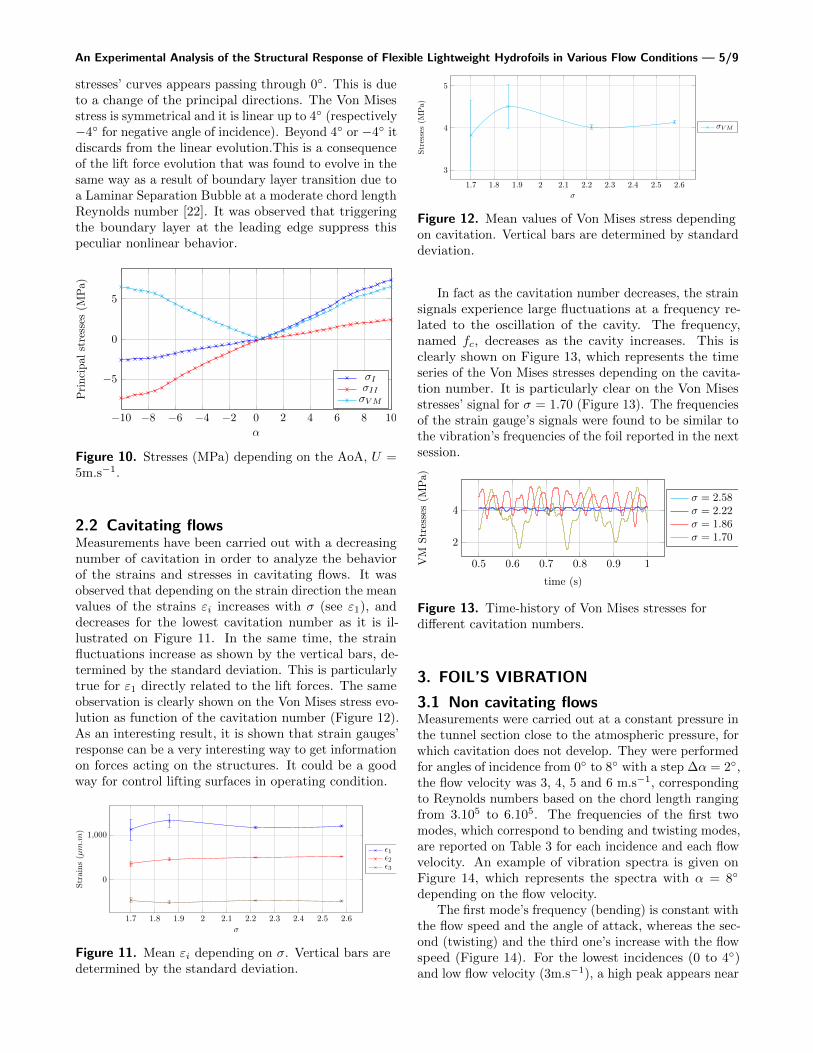
It is observed that the strains are linear up to 3◦.Then they discard from the linear trend. This is particu-larly true for ε1 that is highly related to the lift. Figure10 shows the principal stresses (2) and the Von Misesstresses (3). As shown, an inversion of the principal
An Experimental Analysis of the Structural Response of Flexible Lightweight Hydrofoils in Various Flow Conditions — 5/9
stresses’ curves appears passing through 0◦. This is dueto a change of the principal directions. The Von Misesstress is symmetrical and it is linear up to 4◦ (respectively−4◦ for negative angle of incidence). Beyond 4◦ or −4◦ itdiscards from the linear evolution.This is a consequenceof the lift force evolution that was found to evolve in thesame way as a result of boundary layer transition due toa Laminar Separation Bubble at a moderate chord lengthReynolds number [22]. It was observed that triggeringthe boundary layer at the leading edge suppress thispeculiar nonlinear behavior.
−10 −8 −6 −4 −2 0 2 4 6 8 10
−5
0
5
α
Pri
ncip
alst
ress
es(M
Pa)
σIσIIσVM
Figure 10. Stresses (MPa) depending on the AoA, U =5m.s−1.
2.2 Cavitating flowsMeasurements have been carried out with a decreasingnumber of cavitation in order to analyze the behaviorof the strains and stresses in cavitating flows. It wasobserved that depending on the strain direction the meanvalues of the strains εi increases with σ (see ε1), anddecreases for the lowest cavitation number as it is il-lustrated on Figure 11. In the same time, the strainfluctuations increase as shown by the vertical bars, de-termined by the standard deviation. This is particularlytrue for ε1 directly related to the lift forces. The sameobservation is clearly shown on the Von Mises stress evo-lution as function of the cavitation number (Figure 12).As an interesting result, it is shown that strain gauges’response can be a very interesting way to get informationon forces acting on the structures. It could be a goodway for control lifting surfaces in operating condition.
1.7 1.8 1.9 2 2.1 2.2 2.3 2.4 2.5 2.6
0
1,000
σ
Stra
ins
(µm.m
)
ε1ε2ε3
Figure 11. Mean εi depending on σ. Vertical bars aredetermined by the standard deviation.
1.7 1.8 1.9 2 2.1 2.2 2.3 2.4 2.5 2.6
3
4
5
σ
Stre
sses
(MPa)
σVM
Figure 12. Mean values of Von Mises stress dependingon cavitation. Vertical bars are determined by standarddeviation.
In fact as the cavitation number decreases, the strainsignals experience large fluctuations at a frequency re-lated to the oscillation of the cavity. The frequency,named fc, decreases as the cavity increases. This isclearly shown on Figure 13, which represents the timeseries of the Von Mises stresses depending on the cavita-tion number. It is particularly clear on the Von Misesstresses’ signal for σ = 1.70 (Figure 13). The frequenciesof the strain gauge’s signals were found to be similar tothe vibration’s frequencies of the foil reported in the nextsession.
0.5 0.6 0.7 0.8 0.9 1
2
4
time (s)
VM
Stre
sses
(MPa)
σ = 2.58σ = 2.22σ = 1.86σ = 1.70
Figure 13. Time-history of Von Mises stresses fordifferent cavitation numbers.
3. FOIL’S VIBRATION
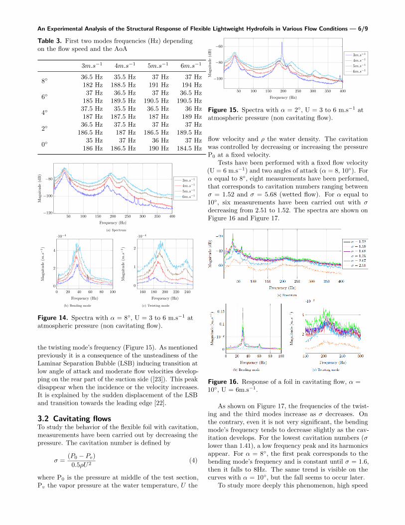
3.1 Non cavitating flowsMeasurements were carried out at a constant pressure inthe tunnel section close to the atmospheric pressure, forwhich cavitation does not develop. They were performedfor angles of incidence from 0◦ to 8◦ with a step ∆α = 2◦,the flow velocity was 3, 4, 5 and 6 m.s−1, correspondingto Reynolds numbers based on the chord length rangingfrom 3.105 to 6.105. The frequencies of the first twomodes, which correspond to bending and twisting modes,are reported on Table 3 for each incidence and each flowvelocity. An example of vibration spectra is given onFigure 14, which represents the spectra with α = 8◦
depending on the flow velocity.The first mode’s frequency (bending) is constant with
the flow speed and the angle of attack, whereas the sec-ond (twisting) and the third one’s increase with the flowspeed (Figure 14). For the lowest incidences (0 to 4◦)and low flow velocity (3m.s−1), a high peak appears near
An Experimental Analysis of the Structural Response of Flexible Lightweight Hydrofoils in Various Flow Conditions — 6/9
Table 3. First two modes frequencies (Hz) dependingon the flow speed and the AoA
3m.s−1 4m.s−1 5m.s−1 6m.s−1
8◦36.5 Hz 35.5 Hz 37 Hz 37 Hz182 Hz 188.5 Hz 191 Hz 194 Hz
6◦37 Hz 36.5 Hz 37 Hz 36.5 Hz
185 Hz 189.5 Hz 190.5 Hz 190.5 Hz
4◦37.5 Hz 35.5 Hz 36.5 Hz 36 Hz187 Hz 187.5 Hz 187 Hz 189 Hz
2◦36.5 Hz 37.5 Hz 37 Hz 37 Hz
186.5 Hz 187 Hz 186.5 Hz 189.5 Hz
0◦35 Hz 37 Hz 36 Hz 37 Hz
186 Hz 186.5 Hz 190 Hz 184.5 Hz
50 100 150 200 250 300 350 400−120
−100
−80
Frequency (Hz)
Mag
nitu
de(d
B)
3m.s−1
4m.s−1
5m.s−1
6m.s−1
(a) Spectrum
0 20 40 60 80 100
0
2
4
·10−4
Frequency (Hz)
Mag
nitu
de(m
.s−1)
(b) Bending mode
160 180 200 220 240
0
1
2
·10−4
Frequency (Hz)
Mag
nitu
de(m
.s−1)
(c) Twisting mode
Figure 14. Spectra with α = 8◦, U = 3 to 6 m.s−1 atatmospheric pressure (non cavitating flow).
the twisting mode’s frequency (Figure 15). As mentionedpreviously it is a consequence of the unsteadiness of theLaminar Separation Bubble (LSB) inducing transition atlow angle of attack and moderate flow velocities develop-ping on the rear part of the suction side ([23]). This peakdisappear when the incidence or the velocity increases.It is explained by the sudden displacement of the LSBand transition towards the leading edge [22].
3.2 Cavitating flowsTo study the behavior of the flexible foil with cavitation,measurements have been carried out by decreasing thepressure. The cavitation number is defined by
σ =(P0 − Pv)
0.5ρU2(4)
where P0 is the pressure at middle of the test section,Pv the vapor pressure at the water temperature, U the
50 100 150 200 250 300 350 400
−100
−80
−60
Frequency (Hz)
Mag
nitu
de(d
B)
3m.s−1
4m.s−1
5m.s−1
6m.s−1
Figure 15. Spectra with α = 2◦, U = 3 to 6 m.s−1 atatmospheric pressure (non cavitating flow).
flow velocity and ρ the water density. The cavitationwas controlled by decreasing or increasing the pressureP0 at a fixed velocity.
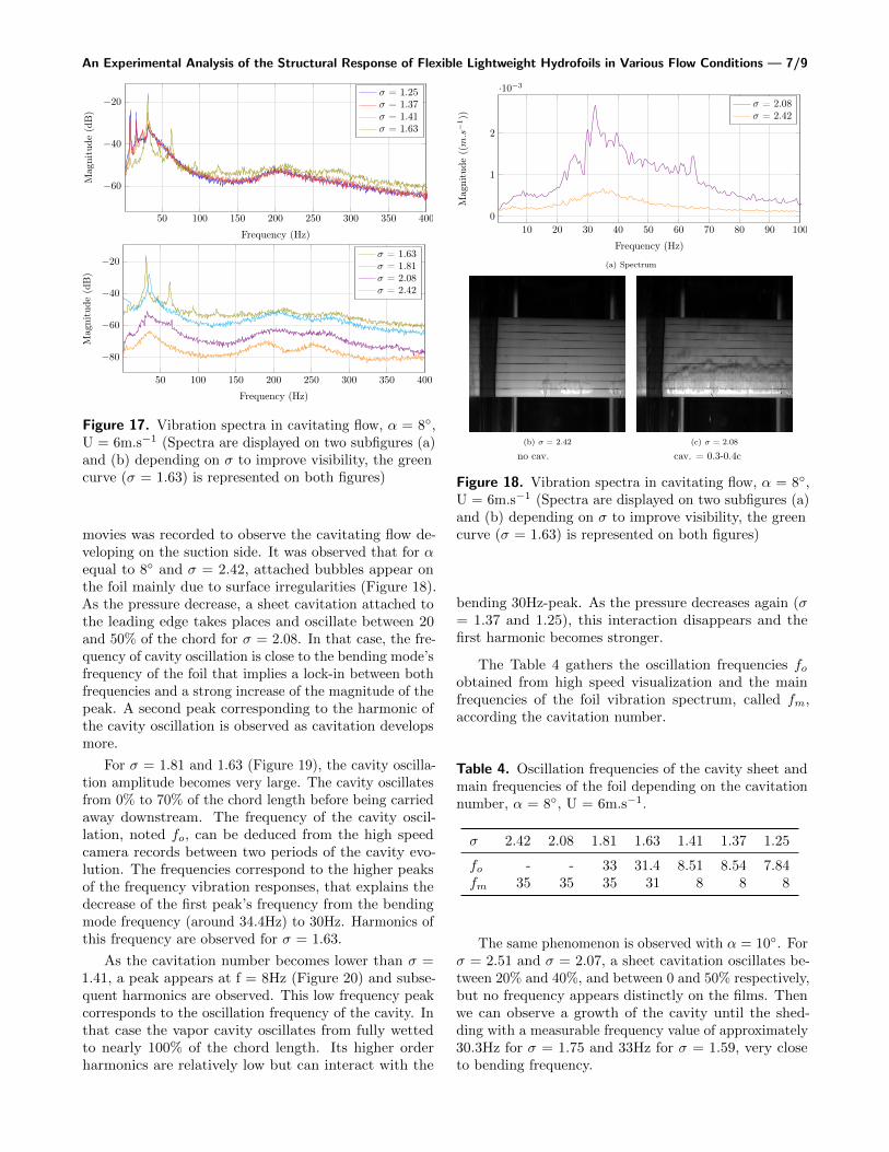
Tests have been performed with a fixed flow velocity(U = 6 m.s−1) and two angles of attack (α = 8, 10◦). Forα equal to 8◦, eight measurements have been performed,that corresponds to cavitation numbers ranging betweenσ = 1.52 and σ = 5.68 (wetted flow). For α equal to10◦, six measurements have been carried out with σdecreasing from 2.51 to 1.52. The spectra are shown onFigure 16 and Figure 17.
Figure 16. Response of a foil in cavitating flow, α =10◦, U = 6m.s−1.
As shown on Figure 17, the frequencies of the twist-ing and the third modes increase as σ decreases. Onthe contrary, even it is not very significant, the bendingmode’s frequency tends to decrease slightly as the cav-itation develops. For the lowest cavitation numbers (σlower than 1.41), a low frequency peak and its harmonicsappear. For α = 8◦, the first peak corresponds to thebending mode’s frequency and is constant until σ = 1.6,then it falls to 8Hz. The same trend is visible on thecurves with α = 10◦, but the fall seems to occur later.
To study more deeply this phenomenon, high speed
An Experimental Analysis of the Structural Response of Flexible Lightweight Hydrofoils in Various Flow Conditions — 7/9
50 100 150 200 250 300 350 400
−60
−40
−20
Frequency (Hz)
Mag
nitu
de(d
B)
σ = 1.25σ = 1.37σ = 1.41σ = 1.63
50 100 150 200 250 300 350 400
−80
−60
−40
−20
Frequency (Hz)
Mag
nitu
de(d
B)
σ = 1.63σ = 1.81σ = 2.08σ = 2.42
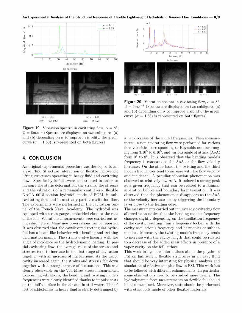
Figure 17. Vibration spectra in cavitating flow, α = 8◦,U = 6m.s−1 (Spectra are displayed on two subfigures (a)and (b) depending on σ to improve visibility, the greencurve (σ = 1.63) is represented on both figures)
movies was recorded to observe the cavitating flow de-veloping on the suction side. It was observed that for αequal to 8◦ and σ = 2.42, attached bubbles appear onthe foil mainly due to surface irregularities (Figure 18).As the pressure decrease, a sheet cavitation attached tothe leading edge takes places and oscillate between 20and 50% of the chord for σ = 2.08. In that case, the fre-quency of cavity oscillation is close to the bending mode’sfrequency of the foil that implies a lock-in between bothfrequencies and a strong increase of the magnitude of thepeak. A second peak corresponding to the harmonic ofthe cavity oscillation is observed as cavitation developsmore.
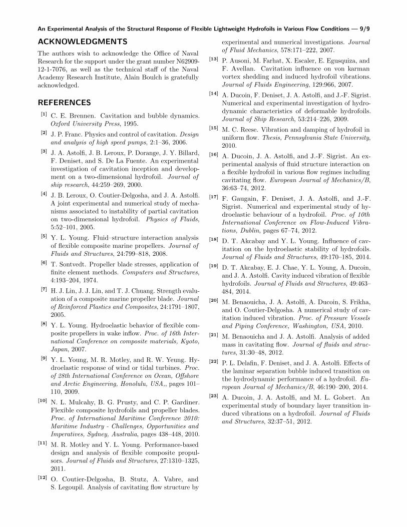
For σ = 1.81 and 1.63 (Figure 19), the cavity oscilla-tion amplitude becomes very large. The cavity oscillatesfrom 0% to 70% of the chord length before being carriedaway downstream. The frequency of the cavity oscil-lation, noted fo, can be deduced from the high speedcamera records between two periods of the cavity evo-lution. The frequencies correspond to the higher peaksof the frequency vibration responses, that explains thedecrease of the first peak’s frequency from the bendingmode frequency (around 34.4Hz) to 30Hz. Harmonics ofthis frequency are observed for σ = 1.63.
As the cavitation number becomes lower than σ =1.41, a peak appears at f = 8Hz (Figure 20) and subse-quent harmonics are observed. This low frequency peakcorresponds to the oscillation frequency of the cavity. Inthat case the vapor cavity oscillates from fully wettedto nearly 100% of the chord length. Its higher orderharmonics are relatively low but can interact with the
10 20 30 40 50 60 70 80 90 100
0
1
2
·10−3
Frequency (Hz)
Mag
nitu
de((m.s
−1))
σ = 2.08σ = 2.42
(a) Spectrum
(b) σ = 2.42 (c) σ = 2.08
no cav. cav. = 0.3-0.4c
Figure 18. Vibration spectra in cavitating flow, α = 8◦,U = 6m.s−1 (Spectra are displayed on two subfigures (a)and (b) depending on σ to improve visibility, the greencurve (σ = 1.63) is represented on both figures)
bending 30Hz-peak. As the pressure decreases again (σ= 1.37 and 1.25), this interaction disappears and thefirst harmonic becomes stronger.
The Table 4 gathers the oscillation frequencies foobtained from high speed visualization and the mainfrequencies of the foil vibration spectrum, called fm,according the cavitation number.
Table 4. Oscillation frequencies of the cavity sheet andmain frequencies of the foil depending on the cavitationnumber, α = 8◦, U = 6m.s−1.
σ 2.42 2.08 1.81 1.63 1.41 1.37 1.25
fo - - 33 31.4 8.51 8.54 7.84fm 35 35 35 31 8 8 8
The same phenomenon is observed with α = 10◦. Forσ = 2.51 and σ = 2.07, a sheet cavitation oscillates be-tween 20% and 40%, and between 0 and 50% respectively,but no frequency appears distinctly on the films. Thenwe can observe a growth of the cavity until the shed-ding with a measurable frequency value of approximately30.3Hz for σ = 1.75 and 33Hz for σ = 1.59, very closeto bending frequency.
An Experimental Analysis of the Structural Response of Flexible Lightweight Hydrofoils in Various Flow Conditions — 8/9
10 20 30 40 50 60 70 80 90 100
0
5 · 10−2
0.1
0.15
Frequency (Hz)
Mag
nitu
de((m.s
−1))
σ = 1.81σ = 1.63
(a) Spectrum
(b) σ = 1.81 (c) σ = 1.63
cav. = 0.3-0.6c cav. = 0-0.7c
Figure 19. Vibration spectra in cavitating flow, α = 8◦,U = 6m.s−1 (Spectra are displayed on two subfigures (a)and (b) depending on σ to improve visibility, the greencurve (σ = 1.63) is represented on both figures)
4. CONCLUSION
An original experimental procedure was developed to an-alyze Fluid Structure Interaction on flexible lightweightlifting structures operating in heavy fluid and cavitatingflow. Specific hydrofoils were constructed in order tomeasure the static deformation, the strains, the stressesand the vibrations of a rectangular cantilevered flexibleNACA 0015 section hydrofoil made of POM, in sub-cavitating flow and in unsteady partial cavitation flow.The experiments were performed in the cavitation tun-nel of the French Naval Academy. The hydrofoil wasequipped with strain gauges embedded close to the rootof the foil. Vibrations measurements were carried out us-ing vibrometers. Many new observations can be reported.It was observed that the cantilevered rectangular hydro-foil has a beam-like behavior with bending and twistingdeformation mainly. The strains evolve linearly with theangle of incidence as the hydrodynamic loading. In par-tial cavitating flow, the average value of the strains andstresses tend to increase in the first stage of cavitationtogether with an increase of fluctuations. As the vaporcavity increased again, the strains and stresses felt downtogether with a strong increase of fluctuations. This wasclearly observable on the Von-Mises stress measurement.Concerning vibrations, the bending and twisting mode’sfrequencies were clearly identified thanks to impulse testson the foil’s surface in the air and in still water. The ef-fect of added-mass in heavy fluid is clearly determined by
10 20 30 40 50 60 70 80 90 100
0
2
4
6
·10−2
Frequency (Hz)
Mag
nitu
de((m.s
−1))
σ = 1.25σ = 1.37σ = 1.41
(a) Spectrum
(b) σ = 1.25 (c) σ = 1.37 (d) σ = 1.41
Figure 20. Vibration spectra in cavitating flow, α = 8◦,U = 6m.s−1 (Spectra are displayed on two subfigures (a)and (b) depending on σ to improve visibility, the greencurve (σ = 1.63) is represented on both figures)
a net decrease of the modal frequencies. Then measure-ments in non cavitating flow were performed for variousflow velocities corresponding to Reynolds number rang-ing from 3.105 to 6.105, and various angle of attack (AoA)from 0◦ to 8◦. It is observed that the bending mode’sfrequency is constant as the AoA or the flow velocityincreases. On the other hand, the twisting and the thirdmode’s frequencies tend to increase with the flow velocityand incidence. A peculiar vibration phenomenon wasobserved at relatively low AoA. It induced a strong peakat a given frequency that can be related to a laminarseparation bubble and boundary layer transition. It wasobserved that the phenomenon disappears as the AoAor the velocity increases or by triggering the boundarylayer close to the leading edge.The measurements carried out in unsteady cavitating flowallowed us to notice that the bending mode’s frequencychanges slightly depending on the oscillation frequencyof the cavity, resulting from a frequency lock-in with thecavity oscillation’s frequency and harmonics or subhar-monics . Moreover, the twisting mode’s frequency tendsto increase with the cavity length that could be relatedto a decrease of the added mass effects in presence of avapor cavity on the foil surface.This work brings new informations about the physics ofFSI on lightweight flexible structures in a heavy fluidthat should be very interesting for physical analysis andsimulation of relative complex flow in FSI. This work hasto be followed with different enhancements. In particular,some observations need to be studied more deeply. Thehydrodynamic force measurements on flexible foil shouldbe also examined. Moreover, tests should be performedwith other foils made of other flexible materials.
An Experimental Analysis of the Structural Response of Flexible Lightweight Hydrofoils in Various Flow Conditions — 9/9
ACKNOWLEDGMENTS
The authors wish to acknowledge the Office of NavalResearch for the support under the grant number N62909-12-1-7076, as well as the technical staff of the NavalAcademy Research Institute, Alain Boulch is gratefullyacknowledged.
REFERENCES
[1] C. E. Brennen. Cavitation and bubble dynamics.Oxford University Press, 1995.
[2] J. P. Franc. Physics and control of cavitation. Designand analysis of high speed pumps, 2:1–36, 2006.
[3] J. A. Astolfi, J. B. Leroux, P. Dorange, J. Y. Billard,F. Deniset, and S. De La Fuente. An experimentalinvestigation of cavitation inception and develop-ment on a two-dimensional hydrofoil. Journal ofship research, 44:259–269, 2000.
[4] J. B. Leroux, O. Coutier-Delgosha, and J. A. Astolfi.A joint experimental and numerical study of mecha-nisms associated to instability of partial cavitationon two-dimensional hydrofoil. Physics of Fluids,5:52–101, 2005.
[5] Y. L. Young. Fluid–structure interaction analysisof flexible composite marine propellers. Journal ofFluids and Structures, 24:799–818, 2008.
[6] T. Sontvedt. Propeller blade stresses, application offinite element methods. Computers and Structures,4:193–204, 1974.
[7] H. J. Lin, J. J. Lin, and T. J. Chuang. Strength evalu-ation of a composite marine propeller blade. Journalof Reinforced Plastics and Composites, 24:1791–1807,2005.
[8] Y. L. Young. Hydroelastic behavior of flexible com-posite propellers in wake inflow. Proc. of 16th Inter-national Conference on composite materials, Kyoto,Japan, 2007.
[9] Y. L. Young, M. R. Motley, and R. W. Yeung. Hy-droelastic response of wind or tidal turbines. Proc.of 28th International Conference on Ocean, Offshoreand Arctic Engineering, Honolulu, USA,, pages 101–110, 2009.
[10] N. L. Mulcahy, B. G. Prusty, and C. P. Gardiner.Flexible composite hydrofoils and propeller blades.Proc. of International Maritime Conference 2010:Maritime Industry - Challenges, Opportunities andImperatives, Sydney, Australia, pages 438–448, 2010.
[11] M. R. Motley and Y. L. Young. Performance-baseddesign and analysis of flexible composite propul-sors. Journal of Fluids and Structures, 27:1310–1325,2011.
[12] O. Coutier-Delgosha, B. Stutz, A. Vabre, andS. Legoupil. Analysis of cavitating flow structure by
experimental and numerical investigations. Journalof Fluid Mechanics, 578:171–222, 2007.
[13] P. Ausoni, M. Farhat, X. Escaler, E. Egusquiza, andF. Avellan. Cavitation influence on von karmanvortex shedding and induced hydrofoil vibrations.Journal of Fluids Engineering, 129:966, 2007.
[14] A. Ducoin, F. Deniset, J. A. Astolfi, and J.-F. Sigrist.Numerical and experimental investigation of hydro-dynamic characteristics of deformable hydrofoils.Journal of Ship Research, 53:214–226, 2009.
[15] M. C. Reese. Vibration and damping of hydrofoil inuniform flow. Thesis, Pennsylvania State University,2010.
[16] A. Ducoin, J. A. Astolfi, and J.-F. Sigrist. An ex-perimental analysis of fluid structure interaction ona flexible hydrofoil in various flow regimes includingcavitating flow. European Journal of Mechanics/B,36:63–74, 2012.
[17] F. Gaugain, F. Deniset, J. A. Astolfi, and J.-F.Sigrist. Numerical and experimental study of hy-droelastic behaviour of a hydrofoil. Proc. of 10thInternational Conference on Flow-Induced Vibra-tions, Dublin, pages 67–74, 2012.
[18] D. T. Akcabay and Y. L. Young. Influence of cav-itation on the hydroelastic stability of hydrofoils.Journal of Fluids and Structures, 49:170–185, 2014.
[19] D. T. Akcabay, E. J. Chae, Y. L. Young, A. Ducoin,and J. A. Astolfi. Cavity induced vibration of flexiblehydrofoils. Journal of Fluids and Structures, 49:463–484, 2014.
[20] M. Benaouicha, J. A. Astolfi, A. Ducoin, S. Frikha,and O. Coutier-Delgosha. A numerical study of cav-itation induced vibration. Proc. of Pressure Vesselsand Piping Conference, Washington, USA, 2010.
[21] M. Benaouicha and J. A. Astolfi. Analysis of addedmass in cavitating flow. Journal of fluids and struc-tures, 31:30–48, 2012.
[22] P. L. Delafin, F. Deniset, and J. A. Astolfi. Effects ofthe laminar separation bubble induced transition onthe hydrodynamic performance of a hydrofoil. Eu-ropean Journal of Mechanics/B, 46:190–200, 2014.
[23] A. Ducoin, J. A. Astolfi, and M. L. Gobert. Anexperimental study of boundary layer transition in-duced vibrations on a hydrofoil. Journal of Fluidsand Structures, 32:37–51, 2012.