Embed Size (px)
Citation preview
Influence of Geometry Simplifications and NumericalParameters in 3D URANS Liquid-Gas Flow Simulations ofa Radial Pump with an Eulerian Mono-DispersedTwo-Phase ModelTim Müller1*, Phillip Limbach1, Romuald Skoda1
SYM
POSI
A
ON ROTATING MACHIN
ERY
ISROMAC 2016
InternationalSymposium on
TransportPhenomena andDynamics of
Rotating Machinery
Hawaii, Honolulu
April 10-15, 2016
Abstract3D numerical flow simulations of liquid-gas mixtures in a radial research pump with annulus casing andlow rotation speed are performed with ANSYS CFX and a mono-dispersed multi-phase and the SSTturbulence model. The drag force is approximated by the Schiller Nauman model while other interfacialforces are neglected. Both, liquid and gaseous phase are treated incompressible. The inlet gas volumefraction (IGVF) is varied between 3 % and 5 % for two flow rates. The reduction of the full impellergeometry to a single channel computational model has a minor effect on the results. The simulationsshould be performed in the absolute frame of reference since the choice of a relative impeller referenceframe yields spurious gas accumulations at the rotor-stator interface. The achievable solver residuumdecrease and the simulation results are highly grid sensitive. Although a comparison to measurementdata reveals that the gas accumulation is predicted approximately at the expected location within theblade channel, significant deviations to the data remain for the blade pressure distribution. The head dropdue to the increase of IGVF can only qualitatively be predicted. It is assumed that a multi-dispersedmultiphase model including bubble coalescence must be taken into account to improve the computationalprediction of liquid-gas mixture flow in radial pumps.
1Chair of Hydraulic Fluid Machinery, Ruhr-Universität Bochum, Germany*Corresponding author: [email protected]
INTRODUCTIONUsually, radial centrifugal pumps with low specific speed aredesigned for pure liquids. For the transport of liquid-gas mix-tures, even at very low values of the IGVF of 1 or 2 % the headmay drop, usually more significantly in part and overload (lowand high flow rates) operation conditions than for nominalload. As a source of the head drop, phase separation and largegas accumulations within the blade channel due to the Coriolisforce, the slip between bubbles and liquid as well as pressuregradients in cross-flow direction have been identified [1]. Inaxial pumps a secondary flow reduces the tendency of phaseseparation, so that axial pumps can handle higher gas volumefractions than radial ones [2].
Several experimental studies of the two-phase flow char-acteristics of radial pumps [3, 4, 5, 6] confirm the significantdecrease of head in part and overload operation conditions.In order to reveal the physical mechanisms of gas accumula-tion in more detail, Minemura and Murakami [7] perform aCFD study of a radial pump impeller and analyze the motionof air bubbles including the effects of the drag and inertiaforce as well as density differences between both phases. Bycomparing their results to experimental data, they verify thatthe motion of bubbles in the impeller is controlled by thecorresponding drag force and the pressure gradient aroundthe bubble. The bubble motion deviates increasingly from the
liquid streamlines with increasing bubble diameter. Minemuraand Uchiyama [8] as well as Pak and Lee [9] numerically in-vestigate the region of bubble accumulation in a radial pump.The bubbles move to the shroud of the impeller as well as tothe suction surface of the blade. Both, [8] and [9] confirm thatthe head drop is caused by the phase separation and large gasaccumulation within the blade channel.
In 3D simulations of radial pumps [10, 11, 12] it is shownthat for low IGVF the predicted head is in good agreementwith experimental data while with increasing IGVF, the ex-perimentally observed head drop is not captured by the sim-ulation and the head is overestimated for higher gas load.Systematic deviations between predicted and measured headare also found for the numerical simulation of a high specificspeed pump [11, 13]. Hence, the present investigation willcontribute to figure out possible sources of mis-match of thesimulation results to the experimental data.
In a previous study of the present authors [12] the headdrop vs. IGVF in a single channel model (SCM) of a ra-dial pump has been evaluated using the state of the art CFDsolver ANSYS CFX. Up to an IGVF of 3 % the head dropis qualitatively correct predicted, whereas for higher IGVFthe deviation between simulation and experiment increases.In figure 1, two-phase flow head vs. flow rate is reprintedfrom [12]. Even for low IGVF the gas accumulation is pre-
Influence of Geometry Simplifications and Numerical Parameters in 3D URANS Liquid-Gas Flow Simulations of a Radial Pumpwith an Eulerian Mono-Dispersed Two-Phase Model — 2/9
dicted in the centre of the channel and neither at the bladewall nor in the vicinity of the leading edge as expected fromthe experimental data. As a consequence, the experimentallyobserved drop of the pressure at the blade pressure side withincreasing flow rate due to gas accumulation is not capturedand an even qualitatively wrong head drop is obtained forparticular operation points: by increasing the flow rate from360 m3/h to 400 m3/h, a qualitatively sound drop of the headhas been figured out with IGVF of 3 %, whereas a head risehas been predicted due to a shedding of gas clouds from theaccumulated gas regions for IGVF of 5 % in contradiction tothe measurements, cf. figure 1.
Figure 1. Head vs. flow rate, reprinted from [12].
Different reasons are assumed for the mis-location of thegas accumulation in the simulation:
• Simplification of the radial pump geometry to a singlechannel model,• Assumption that the findings of the single-phase flow
grid study are transferable to the two-phase flow,• Neglect of the lift force,• Assumption of a mono-dispersed phase distribution and
neglect of break-up and coalescence,• Both phases are treated as incompressible.
In order to firstly exclude numerical reasons for the mis-match, the aim of the present paper is the assessment of theinfluence of the geometry simplification from a full geometrymodel to a single channel model, the reference frame and gridimpact on the location and intensity of the gas accumulation.
1. METHODOLOGY1.1 Pump characteristicsThe present numerical study is based on experimental inves-tigations by Suryawijaya and Kosyna [14] and Kosyna andWulff [15]. Experimental pump performance data as well asblade pressure profiles are available for the validation. Thevalidation data has been obtained with a static inlet pressureof 1.2 bar and an ambient air temperature for all investigatedoperation conditions.
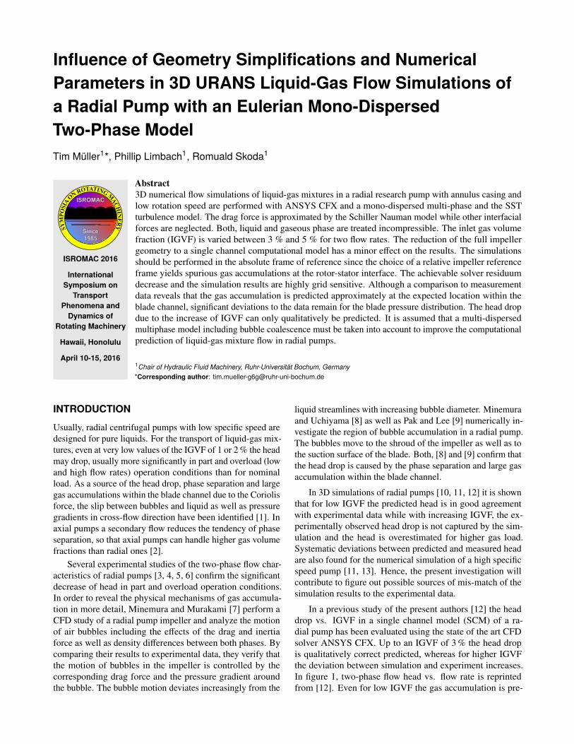
The closed five blade impeller geometry is optimized forflow visualization within the impeller as well as blade pres-sure measurements by a simple 2D blade design based ontwo circular arcs. A rotation-symmetrical annulus chamber
Figure 2. Cross section of the centrifugal pump [12].
instead of a volute yields essentially uniform flow conditionsdownstream of the impeller, cf. figure 2. The pump perfor-mance data is listed in table 1 and the pump geometry datain table 2. A highly unsteady flow field as well as differentgas accumulation regions at the blade surface are observedby flow visualizations in a scaled-down (scale 1:0.5) variantof the pump [16, 17]. Although the present CFD study onlyconsiders the original pump [14, 15], the information aboutthe gas accumulation regions from [16, 17] is assumed to betransferable and serves as additional validation data.
Table 1. Pump performance data.
Nominal flow rate Qopt 412 m3/hNominal pump head Hopt 10.16 mNominal rotational speed nopt 540 1/minSpecific speed (1/min, m3/s, m) nq 32 1/min
Table 2. Pump geometry data.
Impeller inlet diameter d1 260 mmBlade inlet width b1 46 mmImpeller blade inlet angle β1 19◦
Impeller outlet diameter d2 556 mmBlade outlet width b2 46 mmImpeller blade outlet angle β2 23◦
Blade thickness s 13 mmBlade shape 2 circular
arc
1.2 Numerical method and two-phase modelThe same approach as in [12] is used and summarized here.The commercial 3D CFD solver ANSYS CFX version 15is used with SST statistical turbulence model [18], double-precision accuracy and second discretization order in spaceand time. The momentum and continuity equation are solvedwith a coupled method and the volume fraction equation issolved in a segregated way. A mono-dispersed phase distri-bution and a constant diameter size of spherical bubbles is
Influence of Geometry Simplifications and Numerical Parameters in 3D URANS Liquid-Gas Flow Simulations of a Radial Pumpwith an Eulerian Mono-Dispersed Two-Phase Model — 3/9
Table 3. CFD setup.
Single-phase flow Two-phase flow
Fluid Water (ρl = 998 kg/m3) Water (ρl = 998 kg/m3), air (ρg = 1.185 kg/m3)Morphology Continuous phase Continuous phase (water), dispersed phase (air)Turbulence model Shear stress transport Shear stress transportInlet boundary Mass flow water Mass flow water and air, IGVFOutlet boundary Static pressure (2 bar) Static pressure (2 bar)Wall boundary Adiabatic, smooth, non-slip condition Adiabatic, smooth, non-slip conditionRotation treatment Transient TransientConvergence criteria Max residuals < 1.e−4, imbalances < 1 %, Max residuals < 1.e−4, imbalances < 1 %
stability of macro (head, torque) andlocal (pressure, velocity) parameters < 1 %
assumed. The Eulerian approach is chosen for the descriptionof the dispersed phase. The pressure field is modeled in ahomogeneous way, thus the phases of water and air share thesame pressure field. In order to allow phase separation, twodifferent velocity fields are resolved (non-homogeneous flow),one for each phase. The turbulence fields are treated in anon-homogeneous way, as well. For unsteady turbulent flowof multiple phases k (k = l, g) the conservation equations ofmass and momentum can be written as follows:
∂
∂t(αk ρk ) + ∇ · (αk ρkuk ) = 0 (1)
∂
∂t(αk ρkuk ) + ∇ · (αk ρkukuk ) =
− αk∇p + ∇ · (αk µk (∇uk + (∇uk )T )) + Mk
(2)
Since to the knowledge of the authors no validated liftmodel is available for the specific flow conditions in a radialpump, i.e. separated turbulent flow and strong pressure gradi-ents due to Coriolis and centrifugal forces, the lift forces areneglected. All other interfacial forces except the drag forcesare neglected, too. The drag force of the gas phase g actingon the liquid phase l is calculated by equation 3.
Ml = −Mg =34
cDρldB
αg���ug − ul
��� (3)
cD = max(24
ReP(1 + 0.15Re0.687
P ),0.44) (4)
ReP =ρl
���ug − ul��� dB
µl(5)
The dimensionless drag coefficient cD in equation 3 isdetermined by the Schiller Naumann drag law [19, 20], cf.equation 4, and the particle Reynolds number by equation 5.Since preliminary tests have shown that an incompressibletreatment of the gas phase enhances the stability of the CFDsolver, both phases are treated as incompressible.
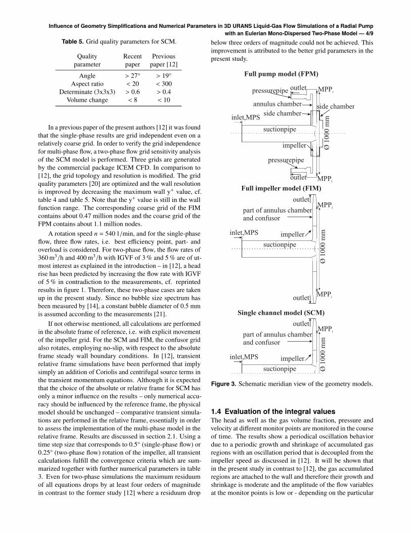
1.3 Numerical setupDue to the rotation-symmetrical annulus chamber, essentiallythe same flow field in each blade channel and the validity ofthe single channel model has been assumed in [12]. However,it has to be clarified in the present study if unsteady effectsmay cause flow un-uniformities from one blade channel to theother which can only be captured by a full-impeller simulation.Therefore, in order to verify the validity of the single channelmodel, three geometry models have been setup, referred toas FPM (full pump model), FIM (full impeller model withsimplified annulus chamber and neglected side chambers) andSCM (single channel model of FIM), cf. schematic meridianview of the models in figure 3.
In the FPM model the full 360° impeller with five bladesand the real geometry of the annulus chamber correspond-ing to the experimental setup with twelve mounted pressurepipes, uniformly distributed in circumferential direction, areconsidered. The length of the pressure as well as suctionpipes corresponds to three times the pipe diameter in order tominimize the effect of the boundary conditions, in particularon the suction side where a part load swirl may develop.
For the FIM, the side chambers are neglected and the an-nulus chamber has been simplified by a radial outflow surfaceand a circular confusor. The confusor reduces the radial out-flow surface to 60 % of impeller outflow surface, avoids flowseparation due to the adverse pressure gradient in the annulusand therefore stabilizes the numerical solver. For the SCMperiodic boundary conditions in circumferential direction areused.
Table 4. Computational grid data for SCM. y+ obtained fortwo-phase flow.
Grid Number Max. Averageresolution of nodes wall y+ wall y+
Coarse ≈ 0.1 million < 400 ≈ 80Medium ≈ 0.3 million < 300 ≈ 70
Fine ≈ 0.9 million < 200 ≈ 50Coarse in [12] ≈ 0.06 million < 450 ≈ 80
Influence of Geometry Simplifications and Numerical Parameters in 3D URANS Liquid-Gas Flow Simulations of a Radial Pumpwith an Eulerian Mono-Dispersed Two-Phase Model — 4/9
Table 5. Grid quality parameters for SCM.
Quality Recent Previousparameter paper paper [12]
Angle > 27° > 19°Aspect ratio < 20 < 300
Determinate (3x3x3) > 0.6 > 0.4Volume change < 8 < 10
In a previous paper of the present authors [12] it was foundthat the single-phase results are grid independent even on arelatively coarse grid. In order to verify the grid independencefor multi-phase flow, a two-phase flow grid sensitivity analysisof the SCM model is performed. Three grids are generatedby the commercial package ICEM CFD. In comparison to[12], the grid topology and resolution is modified. The gridquality parameters [20] are optimized and the wall resolutionis improved by decreasing the maximum wall y+ value, cf.table 4 and table 5. Note that the y+ value is still in the wallfunction range. The corresponding coarse grid of the FIMcontains about 0.47 million nodes and the coarse grid of theFPM contains about 1.1 million nodes.
A rotation speed n = 540 1/min, and for the single-phaseflow, three flow rates, i.e. best efficiency point, part- andoverload is considered. For two-phase flow, the flow rates of360 m3/h and 400 m3/h with IGVF of 3 % and 5 % are of ut-most interest as explained in the introduction – in [12], a headrise has been predicted by increasing the flow rate with IGVFof 5 % in contradiction to the measurements, cf. reprintedresults in figure 1. Therefore, these two-phase cases are takenup in the present study. Since no bubble size spectrum hasbeen measured by [14], a constant bubble diameter of 0.5 mmis assumed according to the measurements [21].
If not otherwise mentioned, all calculations are performedin the absolute frame of reference, i.e. with explicit movementof the impeller grid. For the SCM and FIM, the confusor gridalso rotates, employing no-slip, with respect to the absoluteframe steady wall boundary conditions. In [12], transientrelative frame simulations have been performed that implysimply an addition of Coriolis and centrifugal source terms inthe transient momentum equations. Although it is expectedthat the choice of the absolute or relative frame for SCM hasonly a minor influence on the results – only numerical accu-racy should be influenced by the reference frame, the physicalmodel should be unchanged – comparative transient simula-tions are performed in the relative frame, essentially in orderto assess the implementation of the multi-phase model in therelative frame. Results are discussed in section 2.1. Using atime step size that corresponds to 0.5° (single-phase flow) or0.25° (two-phase flow) rotation of the impeller, all transientcalculations fulfill the convergence criteria which are sum-marized together with further numerical parameters in table3. Even for two-phase simulations the maximum residuumof all equations drops by at least four orders of magnitudein contrast to the former study [12] where a residuum drop
below three orders of magnitude could not be achieved. Thisimprovement is attributed to the better grid parameters in thepresent study.
Figure 3. Schematic meridian view of the geometry models.
1.4 Evaluation of the integral valuesThe head as well as the gas volume fraction, pressure andvelocity at different monitor points are monitored in the courseof time. The results show a periodical oscillation behaviordue to a periodic growth and shrinkage of accumulated gasregions with an oscillation period that is decoupled from theimpeller speed as discussed in [12]. It will be shown thatin the present study in contrast to [12], the gas accumulatedregions are attached to the wall and therefore their growth andshrinkage is moderate and the amplitude of the flow variablesat the monitor points is low or - depending on the particular
Influence of Geometry Simplifications and Numerical Parameters in 3D URANS Liquid-Gas Flow Simulations of a Radial Pumpwith an Eulerian Mono-Dispersed Two-Phase Model — 5/9
operation point and monitor point - the results are even quasi-steady. In any way, the flow values at the monitor point aretime averaged for a sufficiently long time interval.
The evaluation location of the impeller total outlet pres-sure and the head for all three models is chosen at the eightcircumferentially with equal spacing arranged monitor pointsat the rear wall indicated as MPPi in figure 3, i = 1 to 8 whichare located at a constant radius in the annulus, cf. figure 3.These positions correspond to the locations of the probes inthe measurements [14, 15]. The evaluation of the integralvalues of the simulation results follows the same method asthe evaluation of the experimental results. The pump headis determined by the total pressure difference between thearithmetic average of the monitor points pt,MPPi and the totalinlet pressure pt,MPS , cf. figure 3. The transient head is evalu-ated with the instantaneous values of the total pressure at eachtime step and subsequently time-averaged as described above.It has been verified that a time average of the total pressureat each monitor point and a subsequent head evaluation doespractically not change the result.
H =
8∑i=1
pt,MPPi
8 − pt,MPS
gρl(6)
The single-phase flow pump head is calculated by equation6. For the evaluation of the two-phase flow pump head, thedensity of water is replaced by a mixture density at the inlet.Thus the two-phase flow head is determined by equation 7.
H =
8∑i=1
pt,MPPi
8 − pt,MPS
g(ρlαl,MPS + ρgαg,MPS )(7)
Since the pressure field is shared by all fluids, the bladepressure for the single-phase flow as well as the two-phaseflow calculations can be determined by equation 8. In thisequation the blade pressure at any radius pBl, i is calculatedfrom the pressure at radial position i (ps,bl, i ) and the pressureat inlet (ps,MPS).
pBl, i = ps,bl, i − ps,MPS (8)
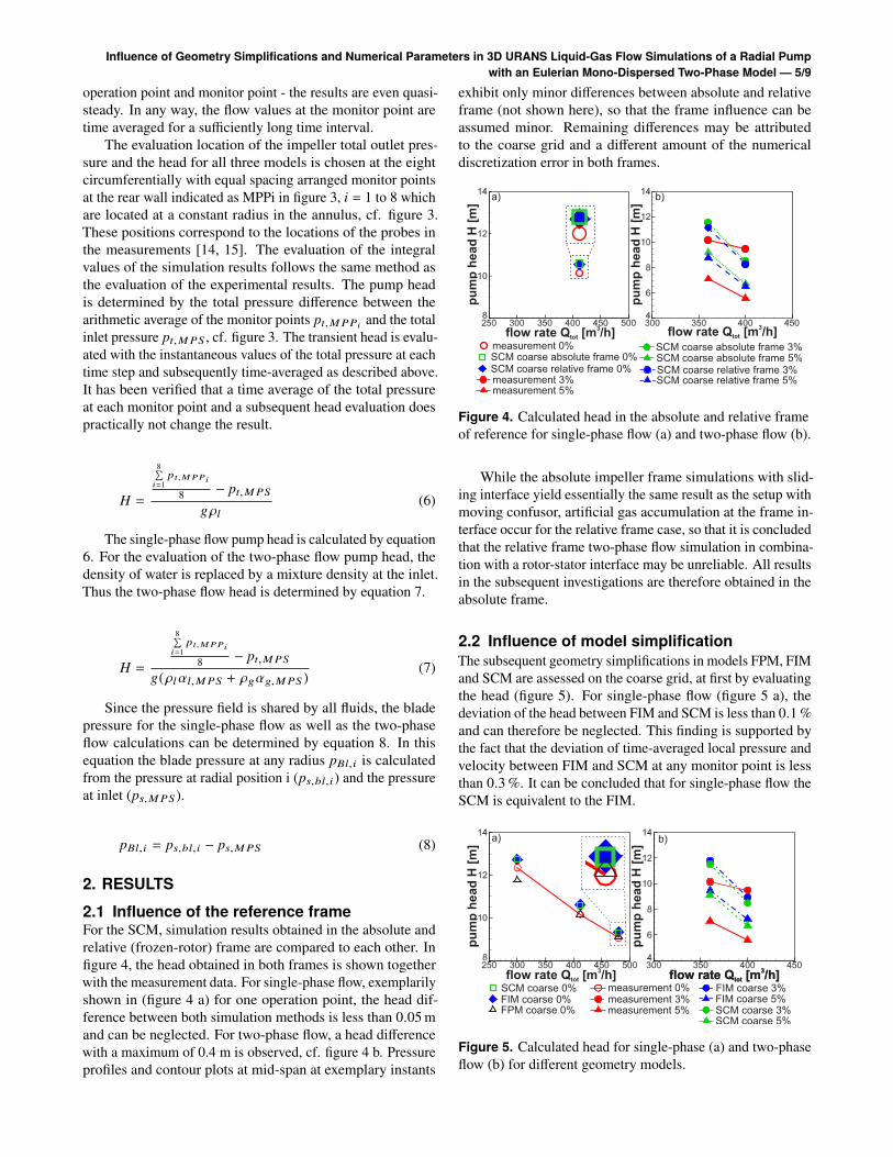
2. RESULTS2.1 Influence of the reference frameFor the SCM, simulation results obtained in the absolute andrelative (frozen-rotor) frame are compared to each other. Infigure 4, the head obtained in both frames is shown togetherwith the measurement data. For single-phase flow, exemplarilyshown in (figure 4 a) for one operation point, the head dif-ference between both simulation methods is less than 0.05 mand can be neglected. For two-phase flow, a head differencewith a maximum of 0.4 m is observed, cf. figure 4 b. Pressureprofiles and contour plots at mid-span at exemplary instants
exhibit only minor differences between absolute and relativeframe (not shown here), so that the frame influence can beassumed minor. Remaining differences may be attributedto the coarse grid and a different amount of the numericaldiscretization error in both frames.
Figure 4. Calculated head in the absolute and relative frameof reference for single-phase flow (a) and two-phase flow (b).
While the absolute impeller frame simulations with slid-ing interface yield essentially the same result as the setup withmoving confusor, artificial gas accumulation at the frame in-terface occur for the relative frame case, so that it is concludedthat the relative frame two-phase flow simulation in combina-tion with a rotor-stator interface may be unreliable. All resultsin the subsequent investigations are therefore obtained in theabsolute frame.
2.2 Influence of model simplificationThe subsequent geometry simplifications in models FPM, FIMand SCM are assessed on the coarse grid, at first by evaluatingthe head (figure 5). For single-phase flow (figure 5 a), thedeviation of the head between FIM and SCM is less than 0.1 %and can therefore be neglected. This finding is supported bythe fact that the deviation of time-averaged local pressure andvelocity between FIM and SCM at any monitor point is lessthan 0.3 %. It can be concluded that for single-phase flow theSCM is equivalent to the FIM.
Figure 5. Calculated head for single-phase (a) and two-phaseflow (b) for different geometry models.
Influence of Geometry Simplifications and Numerical Parameters in 3D URANS Liquid-Gas Flow Simulations of a Radial Pumpwith an Eulerian Mono-Dispersed Two-Phase Model — 6/9
Due to the neglect of the annulus and the side chambers,the head is overpredicted by the SCM as the comparison ofthe FPM with SCM as well as measurement data in figure 5 ashows. Since the deviations between FPM and SCM are moredistinct towards part load, it is assumed that the neglect of theside chambers has a more distinct influence than the neglectof the annulus chamber. The SCM overpredicts the measuredhead by an essentially constant amount whereas the FPM fitsthe data well for nominal and over load. For part load, theFPM underestimates the data significantly, maybe due to theapplication of a statistical URANS turbulence model. Thedeviation to the measurement data is in the same order forSCM and FPM in part load, so that it is concluded that thegeometry simplifications of the SCM and the reduction ofcomputational resources are justified.
Despite the fact that SCM and FIM are equivalent forsingle-phase flow, their equivalence has to be verified for two-phase flow. From flow visualizations [16, 17] it is evidentthat two-phase flow is highly unsteady so that cyclic fluctu-ations from one blade channel to the other may occur whichcannot be captured by the SCM. Although the resolution ofsuch unsteady effects may of course be grid dependent, thecomparison of the SCM and the FIM is done with the coarsegrid in order to figure out if there is at least an indication ofinter-channel interaction.
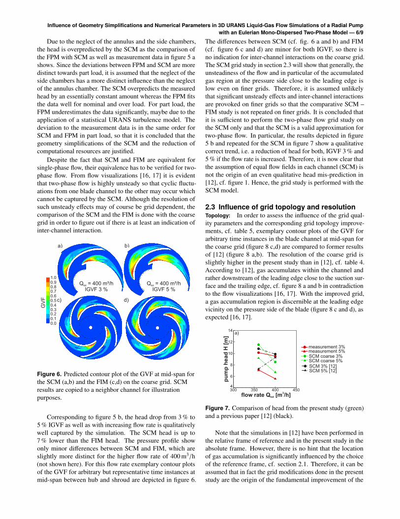
Figure 6. Predicted contour plot of the GVF at mid-span forthe SCM (a,b) and the FIM (c,d) on the coarse grid. SCMresults are copied to a neighbor channel for illustrationpurposes.
Corresponding to figure 5 b, the head drop from 3 % to5 % IGVF as well as with increasing flow rate is qualitativelywell captured by the simulation. The SCM head is up to7 % lower than the FIM head. The pressure profile showonly minor differences between SCM and FIM, which areslightly more distinct for the higher flow rate of 400 m3/h(not shown here). For this flow rate exemplary contour plotsof the GVF for arbitrary but representative time instances atmid-span between hub and shroud are depicted in figure 6.
The differences between SCM (cf. fig. 6 a and b) and FIM(cf. figure 6 c and d) are minor for both IGVF, so there isno indication for inter-channel interactions on the coarse grid.The SCM grid study in section 2.3 will show that generally, theunsteadiness of the flow and in particular of the accumulatedgas region at the pressure side close to the leading edge islow even on finer grids. Therefore, it is assumed unlikelythat significant unsteady effects and inter-channel interactionsare provoked on finer grids so that the comparative SCM –FIM study is not repeated on finer grids. It is concluded thatit is sufficient to perform the two-phase flow grid study onthe SCM only and that the SCM is a valid approximation fortwo-phase flow. In particular, the results depicted in figure5 b and repeated for the SCM in figure 7 show a qualitativecorrect trend, i.e. a reduction of head for both, IGVF 3 % and5 % if the flow rate is increased. Therefore, it is now clear thatthe assumption of equal flow fields in each channel (SCM) isnot the origin of an even qualitative head mis-prediction in[12], cf. figure 1. Hence, the grid study is performed with theSCM model.
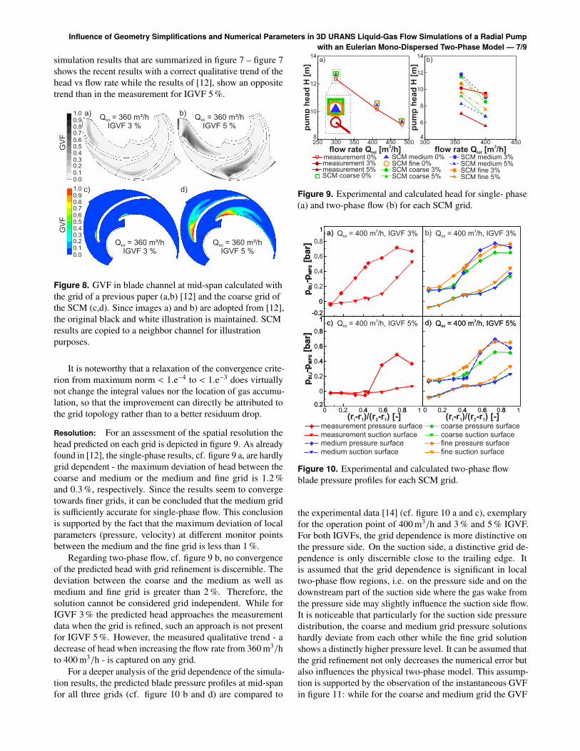
2.3 Influence of grid topology and resolutionTopology: In order to assess the influence of the grid qual-ity parameters and the corresponding grid topology improve-ments, cf. table 5, exemplary contour plots of the GVF forarbitrary time instances in the blade channel at mid-span forthe coarse grid (figure 8 c,d) are compared to former resultsof [12] (figure 8 a,b). The resolution of the coarse grid isslightly higher in the present study than in [12], cf. table 4.According to [12], gas accumulates within the channel andrather downstream of the leading edge close to the suction sur-face and the trailing edge, cf. figure 8 a and b in contradictionto the flow visualizations [16, 17]. With the improved grid,a gas accumulation region is discernible at the leading edgevicinity on the pressure side of the blade (figure 8 c and d), asexpected [16, 17].
Figure 7. Comparison of head from the present study (green)and a previous paper [12] (black).
Note that the simulations in [12] have been performed inthe relative frame of reference and in the present study in theabsolute frame. However, there is no hint that the locationof gas accumulation is significantly influenced by the choiceof the reference frame, cf. section 2.1. Therefore, it can beassumed that in fact the grid modifications done in the presentstudy are the origin of the fundamental improvement of the
Influence of Geometry Simplifications and Numerical Parameters in 3D URANS Liquid-Gas Flow Simulations of a Radial Pumpwith an Eulerian Mono-Dispersed Two-Phase Model — 7/9
simulation results that are summarized in figure 7 – figure 7shows the recent results with a correct qualitative trend of thehead vs flow rate while the results of [12], show an oppositetrend than in the measurement for IGVF 5 %.
Figure 8. GVF in blade channel at mid-span calculated withthe grid of a previous paper (a,b) [12] and the coarse grid ofthe SCM (c,d). Since images a) and b) are adopted from [12],the original black and white illustration is maintained. SCMresults are copied to a neighbor channel for illustrationpurposes.
It is noteworthy that a relaxation of the convergence crite-rion from maximum norm < 1.e−4 to < 1.e−3 does virtuallynot change the integral values nor the location of gas accumu-lation, so that the improvement can directly be attributed tothe grid topology rather than to a better residuum drop.
Resolution: For an assessment of the spatial resolution thehead predicted on each grid is depicted in figure 9. As alreadyfound in [12], the single-phase results, cf. figure 9 a, are hardlygrid dependent - the maximum deviation of head between thecoarse and medium or the medium and fine grid is 1.2 %and 0.3 %, respectively. Since the results seem to convergetowards finer grids, it can be concluded that the medium gridis sufficiently accurate for single-phase flow. This conclusionis supported by the fact that the maximum deviation of localparameters (pressure, velocity) at different monitor pointsbetween the medium and the fine grid is less than 1 %.
Regarding two-phase flow, cf. figure 9 b, no convergenceof the predicted head with grid refinement is discernible. Thedeviation between the coarse and the medium as well asmedium and fine grid is greater than 2 %. Therefore, thesolution cannot be considered grid independent. While forIGVF 3 % the predicted head approaches the measurementdata when the grid is refined, such an approach is not presentfor IGVF 5 %. However, the measured qualitative trend - adecrease of head when increasing the flow rate from 360 m3/hto 400 m3/h - is captured on any grid.
For a deeper analysis of the grid dependence of the simula-tion results, the predicted blade pressure profiles at mid-spanfor all three grids (cf. figure 10 b and d) are compared to
Figure 9. Experimental and calculated head for single- phase(a) and two-phase flow (b) for each SCM grid.
Figure 10. Experimental and calculated two-phase flowblade pressure profiles for each SCM grid.
the experimental data [14] (cf. figure 10 a and c), exemplaryfor the operation point of 400 m3/h and 3 % and 5 % IGVF.For both IGVFs, the grid dependence is more distinctive onthe pressure side. On the suction side, a distinctive grid de-pendence is only discernible close to the trailing edge. Itis assumed that the grid dependence is significant in localtwo-phase flow regions, i.e. on the pressure side and on thedownstream part of the suction side where the gas wake fromthe pressure side may slightly influence the suction side flow.It is noticeable that particularly for the suction side pressuredistribution, the coarse and medium grid pressure solutionshardly deviate from each other while the fine grid solutionshows a distinctly higher pressure level. It can be assumed thatthe grid refinement not only decreases the numerical error butalso influences the physical two-phase model. This assump-tion is supported by the observation of the instantaneous GVFin figure 11: while for the coarse and medium grid the GVF
Influence of Geometry Simplifications and Numerical Parameters in 3D URANS Liquid-Gas Flow Simulations of a Radial Pumpwith an Eulerian Mono-Dispersed Two-Phase Model — 8/9
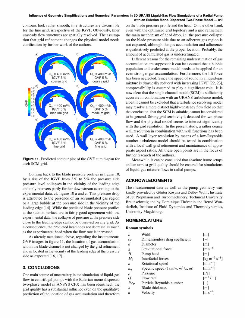
contours look rather smooth, fine structures are discerniblefor the fine grid, irrespective of the IGVF. Obviously, finerunsteady flow structures are spatially resolved. The assump-tion that grid refinement changes the physical model needsclarification by further work of the authors.
Figure 11. Predicted contour plot of the GVF at mid-span foreach SCM grid.
Coming back to the blade pressure profiles in figure 10,by a rise of the IGVF from 3 % to 5 % the pressure sidepressure level collapses in the vicinity of the leading edgeand only recovers partly further downstream according to theexperimental data, cf. figure 10 a and c. This pressure dropis attributed to the presence of an accumulated gas regionor a large bubble at the pressure side in the vicinity of theleading edge [14]. While the predicted blade pressure profilesat the suction surface are in fairly good agreement with theexperimental data, the collapse of pressure at the pressure sideclose to the leading edge cannot be observed on any grid. Asa consequence, the predicted head does not decrease as muchas the experimental head when the flow rate is increased.
As already mentioned above, regarding the instantaneousGVF images in figure 11, the location of gas accumulationwithin the blade channel is not changed by the grid refinementand is located in the vicinity of the leading edge at the pressureside as expected [16, 17].
3. CONCLUSIONSOne main source of uncertainty in the simulation of liquid-gasflow in centrifugal pumps with the Eulerian mono-dispersedtwo-phase model in ANSYS CFX has been identified: thegrid quality has a substantial influence even on the qualitativeprediction of the location of gas accumulation and therefore
on the blade pressure profile and the head. On the other hand,even with the optimized grid topology and a grid refinementthe main mechanism of head drop, i.e. the pressure collapseon the blade pressure side due to an adherent gas region isnot captured, although the gas accumulation and adherenceis qualitatively predicted at the proper location. Probably, theamount of accumulated gas is underestimated.
Different reasons for the remaining underestimation of gasaccumulation are supposed: it can be assumed that a bubblepopulation and coalescence model needs to be applied for aneven stronger gas accumulation. Furthermore, the lift forcehas been neglected. Since the speed of sound in a liquid-gasmixture is drastically reduced with increasing IGVF [22, 23],compressibility is assumed to play a significant role. It isnow clear that the single channel model (SCM) is sufficientlyaccurate in combination with an URANS turbulence model,albeit it cannot be excluded that a turbulence resolving modelmay resolve a more distinct highly-unsteady flow field so thatthe conclusion, that the SCM is suitable, cannot be consideredto be general. Strong grid sensitivity is detected for two-phaseflow and the physical model seems to interact significantlywith the grid resolution. In the present study, a rather coarsewall resolution in combination with wall functions has beenused. A wall layer resolution by means of a low-Reynoldsnumber turbulence model should be tested in combinationwith a local wall grid refinement and maintainance of appro-priate aspect ratios. All these open points are in the focus offurther research of the authors.
Meanwhile, it can be concluded that absolute frame setupsand an utmost grid quality should be ensured for simulationsof liquid-gas mixture flows in radial pumps.
ACKNOWLEDGMENTSThe measurement data as well as the pump geometry waskindly provided by Günter Kosyna and Detlev Wulff, Instituteof Jet Propulsion and Turbomachinery, Technical UniversityBraunschweig and by Dominique Thévenin and Bernd Wun-derlich, Institute of Fluid Dynamics and Thermodynamics,University Magdeburg.
NOMENCLATURERoman symbols
b Width [m]cD Dimensionless drag coefficient [−]d Diameter [m]g Gravitational force [m s−2]H Pump head [m]Mk Interfacial forces [kg m−3 s−1]n Rotational speed [min−1]nq Specific speed (1/min, m3/s, m) [min−1]p Pressure [Pa]Q Flow rate [m3 s−1]ReP Particle Reynolds number [−]s Blade thickness [m]u Velocity [m s−1]
Influence of Geometry Simplifications and Numerical Parameters in 3D URANS Liquid-Gas Flow Simulations of a Radial Pumpwith an Eulerian Mono-Dispersed Two-Phase Model — 9/9
Greek Charactersα Gas volume fraction [−]β Blade angle [°]µ Dynamic viscosity [m2 s−1]ρ Density [kg m−3]
Subscripts
1,2 Impeller position 1 and 2B BubbleBl,bl Bladeg Gaseousk Phasel Liquidopt Best efficiency points Statict Totaltot Total at inlet (liquid + gas)
AbbreviationsCFD Computational fluid dynamicsGVF Gas volume fractionFIM Full impeller modelFPM Full pump modelIGVF Inlet gas volume fractionMPPi Monitor point pressure at radial position iMPS Monitor point suctionSCM Single channel model
REFERENCES[1] S. Sato, A. Furukawa, and Y. Takamatsu. Air-water two-
phase flow performance of centrifugal pump impellerswith various blade angles. JSME Int. Journal JapaneseSoc. Mec. Eng., Series B, 39:223–229, 1996.
[2] J. F. Gülich. Centrifugal Pumps. Springer, 2010.[3] C. A. Cappelino, D. R. Roll, and G. Wilson. Design
considerations and application guidelines for pumpingliquids with entrained gas using open impeller centrifugalpump. Int. Pump User Symposium, 9:51–60, 1992.
[4] A. Furukawa, T. Togoe, S. Sato, and Y. Takamatsu. Funda-mental studies on a tandem bladed impeller of gas/liquidtwo-phase flow centrifugal pump. Memoirs of the Facultyof Engineering Kyushu University, 48:231–240, 1988.
[5] M. Murakami, K. Minemura, and H. Suehiro. Effects ofentrained air on the performance of centrifugal and axialflow pumps. Memoirs of the Faculty of Engineering ofNagoya University, 23:124–133, 1971.
[6] P. Tillack. Förderverhalten von Kreiselpumpen beiviskosem, gasbeladenem Fördermedium. Dissertation,Technical University Kaiserslautern, 1998.
[7] K. Minemura and M. Murakami. A theoretical study onair bubble motion in a centrifugal pump impeller. Proc.ASME/JSME Fluid Eng. Conf., 102:446–455, 1980.
[8] K. Minemura and T. Uchiyama. Three-dimensional cal-culation of air-water two-phase flow in centrifugal pumpimpeller based on a bubbly flow model. Trans. AmericanSoc. of Mech. Eng., 115:766–771, 1993.
[9] E.T. Pak and J.C. Lee. Performance and pressure distribu-tion changes in a centrifugal pump under two-phase flow.Proc. of the Inst. of Mech. Engineers, Part A, 212:165–171, 1998.
[10] K. Minemura and T. Uchiyama. Prediction of pumpperformance under air-water two-phase flow based on abubbly flow model. Trans. American Soc. of Mech. Eng.,115:781–783, 1993.
[11] Z. Y. Yu, Q. Z. Zhang, R. Huan, and S. L. Cao. Numericalanalysis of gas-liquid mixed transport process in a mul-tiphase rotodynamic pump. In IOP Conf. Series: EarthEnviron. Sci., Vol. 15, 2012.
[12] T. Müller, P. Limbach, and R. Skoda. Numerical 3d simu-lation of the gas-liquid flow in a centrifugal pump with aneuler-euler two-phase model and a dispersed phase distri-bution. In Proceedings of the 11th European Conferenceon Turbomachinery, Madrid, Spain, 2015.
[13] J. Caridad, M. Asuaje, F. Kenyery, A. Tremante, andO. Aguillon. Characterization of a centrifugal pumpimpeller under two-phase flow conditions. Journal ofPetroleum Sci. and Eng., 63:18–22, 2008.
[14] P. Suryawijaya and G. Kosyna. Schaufeldruckmessun-gen im rotierenden System an einer Radialpumpe beiGas/Flüssigkeitsgemischförderung. Chemie Ing. Technik,72, 2000.
[15] D. Wulff. personal communication. Institute of JetPropulsion and Turbomachinery, Technical UniversityBraunschweig, 2014.
[16] B. Wunderlich. Experimentelle Untersuchung zumFörderverhalten von Kreiselpumpen bei Flüssigkeits-Gasgemischen. Dissertation, University Magdeburg,1981.
[17] B. Wunderlich. personal communication. Instituteof Fluid Dynamics and Thermodynamics, UniversityMagdeburg, 2014.
[18] F. Menter. Two-equation eddy-viscosity turbulence mod-els for engineering applications. AIAA Journal, 32:1598–1605, 1994.
[19] L. Schiller and A. Naumann. Über die grundlegendenBerechnungen bei Schwerkraftaufbereitung. Zeitschriftdes Vereines deutscher Ingenieure, 77, 1933.
[20] Ansys Inc. Ansys CFX-Solver Theory Guide. Release15.0, Ansys Inc., Canonsburg, PA, USA, 2014.
[21] K. Minemura, M. Murakami, and H. Katagiri. Charac-teristics of centrifugal pump handling air-water mixturesand size of air bubbles in pump impellers. Bulletin of theJSME, 28:2310–2318, 1985.
[22] H.B. Karplus. The velocity of sound in a liquid containinggas bubbles. J. Acoust. Soc. Am., 29, 1957.
[23] D. Mc Williams and R.K. Duggins. Speed of sound inbubbly liquids. Proceedings of the Institution of Mechan-ical Engineers, 184:102–107, 1969.