Embed Size (px)
Citation preview

IEEE TRANSACTIONS ON TRANSPORTATION ELECTRIFICATION, VOL. 5, NO. 1, MARCH 2019 239
An Integrated Design and Control OptimizationFramework for Hybrid Military Vehicle Using
Lithium-Ion Battery and Supercapacitor asEnergy Storage Devices
Abdullah-Al Mamun , Zifan Liu , Denise M. Rizzo, and Simona Onori , Senior Member, IEEE
Abstract— One of the existing challenges toward the elec-trification of military vehicles is the selection of the mostsuitable energy storage device. Moreover, a single energy storagetechnology might not provide the most benefit out of powertrainelectrification. In this paper, a generalized framework for thesimultaneous selection of the optimal energy storage device, in theform of a standalone or hybrid solution, and online energymanagement is presented. This paper investigates the cooperationof energy-dense Li-ion batteries and power-dense supercapacitorsto assist engine operation in a series hybrid electric militarytruck. Pontryagin’s minimum principle is adopted as the energymanagement strategy in a forward-looking vehicle simulator,in which the optimal design and control parameters are foundusing particle swarm optimization. Simulation results show thatadopting a hybrid energy storage system reduces fuel consump-tion by 13% compared to the case of battery-only hybridizedpowertrain.
Index Terms— Design optimization, energy management,Li-ion battery, portraying’s minimum principle (PMP),supercapacitor (SC).
I. INTRODUCTION
THANKS to its significant fuel saving potential, the pow-ertrain hybridization technology is finding the path into
different vehicle classes, from light-duty passenger vehiclesto heavy-duty military trucks [1]. In military applications,hybridization of the powertrain can provide the increasedtactical capability of military vehicles by increasing the avail-able onboard power, along with reducing the battlefield fuelcosts [2], [3].
There are various energy storage system (ESS) candidatesfor the alternative energy sources in hybrid electric vehicles(HEVs). Li-ion battery technology is the most commonly used
Manuscript received June 15, 2018; revised August 23, 2018; acceptedAugust 28, 2018. Date of publication September 6, 2018; date of currentversion March 19, 2019. This work was supported by the ARC at the Uni-versity of Michigan under Cooperative Agreement W56HZV-14-2-0001 withthe U.S. Army Tank Automotive Research, Development, and EngineeringCenter, Warren, MI, USA. (Corresponding author: Simona Onori.)
A.-A. Mamun and Z. Liu are with the Department of AutomotiveEngineering, Clemson University, Greenville, SC 29607 USA (e-mail:[email protected]; [email protected]).
D. M. Rizzo is with the U.S. Army Tank Automotive Research,Development, and Engineering Center, Warren, MI USA (e-mail:[email protected]).
S. Onori is with the Department of Energy Resources Engineering, StanfordUniversity, Stanford, CA 94305 USA (e-mail: [email protected]).
Digital Object Identifier 10.1109/TTE.2018.2869038
device for electrified propulsion systems, nowadays, due toits higher power and energy density and declining cost [4].In addition, the power to propel the vehicle can be furthersupplemented by adding other ESSs [5].
Supercapacitors (SCs) have higher power density comparedto the Li-ion battery allowing effective regeneration when thebattery cannot operate in the regenerative mode [5]. The highpulse power capability, fast transient response, and high effi-ciency during charge and discharge cycles make SCs a viableESS choice to be used in conjunction with Li-ion batteriesin a hybrid ESS (HESS) configuration [6], [7]. This will alsohave positive implications on battery aging as the high-powerdensity storage, i.e., the SC can handle the demanded powerspikes [8], [9].
In the context of this paper, besides an internal combustionengine as the primary mover, a HESS pack consisting ofLi-ion battery and SC is considered in the HEV under study.Proper sizing and power management of such a HESS havethe potential to reduce lifecycle cost and weight of the storagesystem while improving the fuel economy.
In [10], an HESS pack with battery and SC is designedfor an electric bus. The battery pack size is determined withthe required minimal electric range, and dynamic program-ing (DP) is used to find the SC pack size that minimizesthe life cycle cost. In [11], for an HESS pack in a fuelcell HEV, the power rating of each energy storage device isscaled up or down to quantitatively assess the significance ofappropriate sizing on system volume/mass and battery lifetime.In [12], applications of HESS, such as smart grid and HEVusing design optimization techniques, including genetic algo-rithm (GA), particle swarm optimization (PSO), and simulatedannealing are presented. The above-mentioned studies lookonly at optimizing the size of the HESS for given rule-basedenergy management strategies. In contrast, many studies focuson developing control strategies for a given ESS size toachieve certain control objectives, such as minimizing fuelconsumption, battery degradation, and so on. Those strategiescan be categorized into heuristic, near-optimal, and optimalones. Heuristic strategies are usually rule based [13], [14] andlow-pass filter based [15], [16]. Despite their straightforwardimplementation, a large number of calibration efforts arerequired. Optimal control strategies include DP [17], [18],
2332-7782 © 2018 IEEE. Personal use is permitted, but republication/redistribution requires IEEE permission.See http://www.ieee.org/publications_standards/publications/rights/index.html for more information.
Authorized licensed use limited to: Stanford University. Downloaded on March 14,2020 at 20:12:32 UTC from IEEE Xplore. Restrictions apply.

240 IEEE TRANSACTIONS ON TRANSPORTATION ELECTRIFICATION, VOL. 5, NO. 1, MARCH 2019
Pontryagin’s minimum principle (PMP), and equivalent con-sumption minimization strategy (ECMS) [19], [20]. Theygenerate optimal control sequence with a priori informationof the drive cycle and set the optimal performance benchmark,making themselves suitable for offline applications. For onlineimplementation, near-optimal EMS strategies can be usedto pursue the best achievable system efficiency. The modelpredictive control [5], [21] and adaptive PMP/ECMS [22] havebeen discussed for HEV with HESS. They require adaptivetuning of a set of parameters to meet varying real-world powerdemands. However, to explore the full potential of an HESSconfiguration in an HEV, the component sizing and energymanagement should be optimized in an integrated manner.
Combined design optimization and energy management areoften solved in a layered approach. In [23], the GA andrule-based EMS were used to simultaneously optimize themonetary cost and the fuel economy of an HEV with a fuelcell, battery, and SC. The power and state-of-charge (SOC)limits of the rules and the pack sizes are optimized simul-taneously. Masih-Tehrani et al. [24] minimize the monetarycost and battery degradation for an HEV with engine andbattery and SC. In the outer loop, GA iterates across thedesign space for optimal sizing parameters, while in the innerloop, DP searches for optimal control sequences. The designand control parameters are sought iteratively in a two-layerframework. Convex programing recently arises as an effectiveapproach to tackle the HESS design and control problembringing less computational burden if compared with DP [25],[26]. However, a large number of model simplifications intoconvex forms are needed which may neglect important vehicleand component dynamics. The investigation in [27] intro-duced the coupling of GA and ECMS for multiobjectiveoptimization of an HEV with the engine, battery, and SC.A multicriteria decision-making technique is used to chooseamong the solutions with conflicting goals. From this method,it is often difficult to understand the impact of design andcontrol variables on a specific objective which is of principalimportance, such as fuel consumption of military vehicles.
The above-mentioned literature presents the benefits ofusing HESS configuration which motivates this paper to fur-ther explore the combined design optimization and energymanagement of HESS for military vehicle hybridization.However, a rigorous mathematical formulation and solutionapproach that is computationally efficient and general enoughfor a wide range of ESSs and powertrain configurations arestill missing in the existing literature. This paper lays thefoundation of a new optimization framework that simultane-ously accounts for both the control and design variables of ahybrid or electric vehicle powertrain. This paper specificallydevelops an approach using PMP and PSO for combineddesign optimization and energy management of an HESS in anHEV to minimize fuel consumption over a given drive cycle.
The proposed solution method pursued in this paper is basedon the construction of the Hamiltonian function defined in away to include both sizing (number of Li-ion cells and numberof SC cells) and control (power split among the engine,the battery pack, and the SC pack) variables. The proposedoptimization approach also allows the inclusion of additional
Fig. 1. M-ATV [29].
optimization objectives which might be important for differentvehicle types and classes. In the proposed framework, weallow one of the costates of the PMP to dynamically varyover time. Therefore, the proposed optimization frameworkcan be extended to plug-in HEV (PHEV) design and energymanagement where the assumption of a constant costate doesnot hold [28]. To the best of our knowledge, this is the firstwork that formulates such a generalized and combined designand control optimization framework that is applicable acrossa wide range of vehicle classes and also across a wide rangeof electrification choices.
This paper is organized as follows. The models of thevehicle, the battery, the SC, and other components are intro-duced in Section II. The PMP, the PSO, and their integratedformulation are discussed in Section III. Next, five militarydrive cycles are used under the integrated optimization frame-work to find the ESS sizing and energy management strategyacross different driving conditions, and results are presentedin Section IV. Conclusions and future work are outlined inSection V.
II. MODEL DESCRIPTION
This paper uses a notional series hybrid version of amine-resistant ambush-protected all-terrain vehicle (M-ATV),as shown in Fig. 1 [29]. A powertrain model of the serieshybrid M-ATV, obtained from [30], comprises a generator set(genset, Navistar 6.4L 260-kW diesel engine + 265-kW gener-ator), four 95-kW brushless permanent magnet direct currentin-hub motors, and a lithium iron phosphate (LFP) batterypack. In the battery pack, the number of LFP cells in series(Ns,Li) is 130 and the number of cells in parallel (NP,Li) is 10.The genset and the battery pack are connected to the powerbus which provides electric power to the four in-hub motors.The vehicle simulator is set up in a Simulink environmentwhere a PID controller is used as a driver model to find therequired propulsion power by minimizing the vehicle speedfollowing error. Longitudinal dynamics equations are used inthe simulator to simulate the vehicle motion and the genset,and the motors are represented by their quasi-static efficiencymaps. Details of the vehicle simulator can be found in [30].The vehicle simulator has a feedforward fuel control logicwhich is removed to reduce the number of tuning parameters.
Authorized licensed use limited to: Stanford University. Downloaded on March 14,2020 at 20:12:32 UTC from IEEE Xplore. Restrictions apply.
MAMUN et al.: INTEGRATED DESIGN AND CONTROL OPTIMIZATION FRAMEWORK FOR HYBRID MILITARY VEHICLE 241
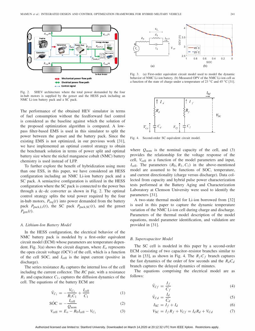
Fig. 2. SHEV architecture where the total power demanded by the fourin-hub motors is supplied by the genset and the HESS pack including anNMC Li-ion battery pack and a SC pack.
The performance of the obtained HEV simulator in termsof fuel consumption without the feedforward fuel controlis considered as the baseline against which the solution ofthe proposed optimization algorithm is compared. A low-pass filter-based EMS is used in this simulator to split thepower between the genset and the battery pack. Since theexisting EMS is not optimized, in our previous work [31],we have implemented an optimal control strategy to obtainthe benchmark solution in terms of power split and optimalbattery size where the nickel manganese cobalt (NMC) batterychemistry is used instead of LFP.
To further explore the benefit of hybridization using morethan one ESS, in this paper, we have considered an HESSconfiguration including an NMC Li-ion battery pack and aSC pack. A semiactive configuration is utilized in the HESSconfiguration where the SC pack is connected to the power busthrough a dc–dc converter as shown in Fig. 2. The optimalcontrol strategy splits the total power required by the fourin-hub motors, Preq(t) into power demanded from the batterypack Ppack,Li(t), the SC pack Ppack,SC(t), and the gensetPgen(t).
A. Lithium-Ion Battery Model
In the HESS configuration, the electrical behavior of theNMC battery pack is modeled by a first-order equivalentcircuit model (ECM) whose parameters are temperature depen-dent. Fig. 3(a) shows the circuit diagram, where Eo representsthe open circuit voltage (OCV) of the cell, which is a functionof the cell SOC, and Icell is the input current (positive indischarge).
The series resistance R0 captures the internal loss of the cellincluding the current collector. The RC pair, with a resistanceR1 and capacitance C1, captures the diffusion dynamics of thecell. The equations of the battery ECM are
VC1 = − VC1
R1C1+ Icell
C1(1)
˙SOC = − Icell
Qnom(2)
Vcell = Eo − R0 Icell − VC1 (3)
Fig. 3. (a) First-order equivalent circuit model used to model the dynamicbehavior of NMC Li-ion battery. (b) Measured OPV of the NMC Li-ion cell asa function of the state of charge under a temperature of 23 ◦C and 45 ◦C [31].
Fig. 4. Second-order SC equivalent circuit model.
where Qnom is the nominal capacity of the cell, and (3)provides the relationship for the voltage response of thecell, Vcell as a function of the model parameters and input,Icell. The parameters (R0, R1, C1) in the above-mentionedmodel are assumed to be functions of SOC, temperature,and current directionality (charge versus discharge). Data col-lected from capacity and hybrid pulse power characterizationtests performed at the Battery Aging and CharacterizationLaboratory at Clemson University were used to identify theparameters [31].
A two-state thermal model for Li-ion borrowed from [32]is used in this paper to capture the dynamic temperaturevariation of the NMC Li-ion cell during charge and discharge.Parameters of the thermal model description of the modelequations, model parameter identification, and validation areprovided in [31].
B. Supercapacitor Model
The SC cell is modeled in this paper by a second-orderECM consisting of two capacitor–resistor branches similar tothat in [33], as shown in Fig. 4. The R f C f branch capturesthe fast dynamics of the order of few seconds and the RdCd
branch captures the delayed dynamics of minutes.The equations comprising the electrical model are as
follows:
VC f = I f
C f(4)
VCd = Id
Cd(5)
ISC = I f + Id (6)
VSC = I f R f + VC f = Id Rd + VCd (7)
Authorized licensed use limited to: Stanford University. Downloaded on March 14,2020 at 20:12:32 UTC from IEEE Xplore. Restrictions apply.

242 IEEE TRANSACTIONS ON TRANSPORTATION ELECTRIFICATION, VOL. 5, NO. 1, MARCH 2019
Fig. 5. For the input current in the top plot, the SC cell voltage is measuredand used to fit the ECM model. Calculated RMS error shows that the identifiedmodel captures the voltage response with an RMS of 10 mV.
TABLE I
ELECTRICAL AND THERMAL PARAMETERS
OF BCAP1500 SC CELL
where C f and Cd are the capacitances of the capacitors in thefast and delayed dynamics branches, and VC f and VCd are thecorresponding voltages across the capacitors. The resistancesof the fast and delayed dynamics branches are R f and Rd .The currents flowing into the fast and delayed branches areI f and Id , respectively; positive current during charge isassumed. The terminal voltage and current through the systemterminals are denoted as VSC and ISC, respectively.
A first-order thermal model is used to capture the SCtemperature change during charge and discharge
CSCTSC = I 2SC R f − hSC(TSC − Tamb) (8)
where CSC is the heat capacity of the cell, TSC is the coretemperature, and hSC is the effective heat transfer coefficientof a cell. The parameters of a BCAP1500 SC [34] areidentified from a pulse current profile and shown in Fig. 5. Thecomparison of the model terminal voltage with the measuredterminal voltage is also shown in Fig. 5.
The identified electrothermal model parameters are com-piled in Table I.
C. DC–DC Converter Model
In this paper, the SC pack is connected in parallel to thepower bus through a bidirectional dc–dc converter in a semiac-tive configuration, as shown in Fig. 6. A dc–dc converter takes
Fig. 6. Input and output voltages of a switching dc–dc converter.
an unregulated voltage as the input and produces a regulatedoutput voltage by means of pulse-width modulation [35]. Thedc–dc converter works in two distinct modes: “buck” and“boost” mode. In this paper, the dc–dc converter is used forvoltage conversion between the dc bus and the SC duringcharge and discharge of the SC. The mode of operation ofthe dc–dc converter changes due to: 1) change in the directionof SC power flow, PSC, during charge and discharge and2) the difference between the SC pack voltage, VSC, and thedc bus voltage, Vbatt. Table II shows the equivalent circuitmodels of the dc–dc converter in different operating modes.In a real system, the single-pole double-throw switch shown inthe circuits of Table II, is realized by semiconductor devicessuch as MOSFETS, diodes, and so on. The inductor L andthe capacitor C form a low-pass filter which allows onlythe dc component of the input voltage to pass through. Theinternal loss in the dc–dc converter is modeled by assuming aresistance (RL) of the inductor winding L. The voltage con-version is achieved through high-frequency switching betweenposition 1 and position 2 and by generating a rectangular waveform. During switching, the fraction of the time the switchis in position 1, which determines the output voltage andis defined as the duty cycle. Duty cycle for the buck mode(0 ≤ Dbuck ≤ 1) and the boost mode (0 ≤ Dboost ≤ 1) isdifferent due to their direction of conversion [35].
Table II also shows four different settings under which thedc–dc converter is operated when used in the HESS configura-tion. During discharge of the SC, PSC > 0, the SC voltage VSCis the input terminal voltage of the dc–dc converter and the dcbus voltage Vbatt is the output terminal voltage. In that case,if SC voltage is higher than the dc bus voltage (VSC > Vbatt),the converter operates in the buck mode. On the other hand,if the SC voltage is lower than dc bus voltage (VSC > Vbatt),the converter operates in the boost mode. A similar conditionarises when the SC pack is charged through power comingfrom the dc bus. In that case, the dc bus voltage Vbatt isthe input terminal voltage of the dc–dc converter and theSC voltage VSC is the output terminal voltage. Similar todischarging, two conditions arise during charging given therelative magnitude of voltage in the input and terminal outputof the converter. Power losses during voltage conversion affectthe conversion efficiency of the dc–dc converter, which isa function of the internal resistance RL of the converter,the duty cycle, and the resistance of the output terminal,determining the final converter efficiency. Since the outputterminal changes upon the direction of current, the efficiency
Authorized licensed use limited to: Stanford University. Downloaded on March 14,2020 at 20:12:32 UTC from IEEE Xplore. Restrictions apply.

MAMUN et al.: INTEGRATED DESIGN AND CONTROL OPTIMIZATION FRAMEWORK FOR HYBRID MILITARY VEHICLE 243
TABLE II
EQUATIONS OF THE VOLTAGE CONVERSION RATIO AND EFFICIENCY FORTHE BIDIRECTIONAL BUCK–BOOST DC–DC CONVERTER UNDER
DIFFERENT OPERATING CONDITIONS [35]
of the converter depends on the battery pack resistance, Rbatt,during the boost mode and SC pack resistance, RSC, in thebuck mode.
For each mode in Table II, first, the voltage conversionratio is found by dividing the output terminal voltage by theinput terminal voltage [35]. The efficiency is computed as theratio of power at the output terminal and the input terminalof the dc–dc converter. Expanding the equation of power and
Fig. 7. Conversion efficiency plot under (a) boost and (b) buck modes ofa dc–dc converter [38]. During discharge of the SC, R = Rbatt, and duringcharging of SC, R = RSC.
using the voltage conversion ratio, the expression of efficiencyis obtained as a function of duty cycle, internal resistance,and resistance of the output terminal of the dc–dc converterη(RL , Dboost/Dbuck, Rbatt, Rsc). The efficiency characteristicsin the buck and boost modes are plotted in Fig. 7 as a functionof duty cycle and ratio of resistances (RL/R) where R is eitherRSC or Rbatt depending on the direction of current. Since theconverter efficiency vary significantly with the duty cycle andresistance of the output terminal, it is important to take theefficiency calculation into account when designing an HESSconfiguration [35]. In this paper, a commercial SIEMENSSINAMICS DCP 120-kW dc–dc converter is chosen to beused with the SC pack. The internal resistance of the converter,which is attributed to the inductor resistance, RL , is assumedto be 0.01 � [36]. The manufacturer limits on voltage, current,and power of the dc–dc converter are listed in [37].
III. PROBLEM FORMULATION AND SOLUTION APPROACH
The goal of this paper is to develop a generalized designoptimization and energy management framework for a militaryHEV equipped with an HESS. The traditional approach to sucha problem is to use a layered approach, where typically anexhaustive search algorithm is used in the outer layer to selectthe design parameters, whereas an energy management algo-rithm is designed in the inner layer by either borrowing toolsfrom optimal control theory or through some heuristics/rule-based strategy. Such a two-layer iterative process can leadto unpractical computational time and complexity. This paperformulates a combined design optimization and energy man-agement problem and outlines a solution approach that relieson the construction of the Hamiltonian function that inte-grates both design and control variables. The optimality ofthe Hamiltonian function can be ensured by enforcing thenecessary conditions using PMP.
Authorized licensed use limited to: Stanford University. Downloaded on March 14,2020 at 20:12:32 UTC from IEEE Xplore. Restrictions apply.

244 IEEE TRANSACTIONS ON TRANSPORTATION ELECTRIFICATION, VOL. 5, NO. 1, MARCH 2019
The goal is to minimize the overall fuel consumption, J ,over a given drive cycle within the time horizon [0, t f ]
J =∫ t f
0mfuel(Pgen)dt (17)
where mfuel is the engine fuel consumption rate (kg/s) andPgen is the power delivered by the engine-genset. The totalelectrical power required by the motors is
Preq(t) = Pgen(t) + PHESS
= Pgen(t) + Ppack,Li(t) + Ppack,sc(t) (18)
where Ppack,Li(t) and Ppack,sc(t) are the battery pack powerand SC pack power, respectively.
The total fuel consumption J can be expressed as a functionof power delivered from the battery pack Ppack,Li(t) and theSC pack Ppack,sc(t) to supplement the genset power Pgen(t) ateach time instant as
J =∫ t f
0mfuel(Ppack, Li(t) + Ppack,SC(t))dt . (19)
Assuming homogeneity in the packs, the battery pack powerin (19) can be expressed as a product of the number ofLi-ion cells in series (Ns,Li), the number of Li-ion cells inparallel (Np,Li), and the power delivered by a single Li-ion cell[Pcell, Li(t)]. Similarly, the SC pack power can be expressed asa product of the number of SCs in series (Ns,SC), the numberof SCs in parallel (Np,SC), and the power delivered by a singleSC cell [Pcell, SC(t)]. Using these relationships in (19), oneobtains
J =∫ t f
0mfuel(Ns,Li · Np,Li · Pcell,Li(t) + Ns,SC · Np,SC
· Pcell,SC(t))dt . (20)
In this paper, it is assumed that the number of Li-ion cells inseries is known and found by dividing the dc bus voltage with anominal voltage of an NMC Li-ion cell. The above-mentionedcost function is constrained by the system states.
In the supervisory controller module, a simpler model ofthe Li-ion battery and SC is used to reduce computationalcomplexity. A zero-order model of the Li-ion battery and afirst-order model for the SC are used, where the voltage acrossthe capacitor of the delayed dynamics branch is the only stateof the SC.
In the following generalized formulation, the battery SOCis indicated as x1(t) and the voltage across the capacitorof the delayed dynamics branch VCd in the SC model isindicated as x2(t). The HESS state vector is then defined asx(t) = [x1(t) x2(t)], where
x1(t) = − Ipack,Li(t)
Qpack
= − Icell,sc(t)
Qnom=
E0 −√
E20 − 4R0 Pcell,Li(t)
2R0 Qnom(21)
x2(t) = − Ipack,sc(t)
Cd,pack= − Icell,sc(t)·Ns,sc
Cd
=(VCd −
√V 2
Cd − 4Rd Pcell,SC(t)) · Ns,sc
2RdCd. (22)
The HESS design variable vector is indicated as v =[Np,Li Ns,sc Np,sc]T . The control variables are the instanta-nious power from a single Li-ion cell and SC cell, u(t) =[u1(t) u2(t)]T = [Pcell,Li(t) Pcell,SC(t)]T . The admissible setof design and control variables is defined as V = [vmin vmax]T
and U(t) = [umin(t) umax(t)]T , respectively. The goal ofthe optimization problem is to find the admissible design andcontrol variables π ∈ � = [U(t) V ]
π(t) ={
u(t) ∈ U(t)
v ∈ V(23)
such that
J =∫ t f
0mfuel (π(t)) dt (24)
is minimized while subjected to (21), (22), and
vmin ≤ v ≤ vmax
x(t f ) − x(to) = �x = 0
umin(t) ≤ u(t) ≤ umax(t)
xmin(t) ≤ x(t) ≤ xmax(t)
Ty,min ≤ Ty(t) ≤ Ty,max
ωy,min ≤ ωy(t) ≤ ωy,max
y = engine, motor, generator.
Based on the above-mentioned problem formulation, a solutionmethod is proposed where the Hamiltonian function is con-structed in such a way that both design and control variablesare included. PMP is a powerful tool that provides a set ofnecessary conditions of optimality in terms of the Hamiltonianfunction. The optimality is guaranteed by selecting the optimalcontrol candidate that produces the lowest total cost.
The PMP has been successfully used in the literature tosolve the optimal power split problem in HEVs [39]. In thispaper, given the cost function (17), the Hamiltonian functionis defined as follows:
H (t, x(t),λ(t), u(t), v)
= mfuel(u(t), v) + λ(t)T · f (t, x(t), u(t), v) (25)
where f is the vector of the state dynamics in (21) and (22)and λ(t) is the vector of costates, e.g., λ(t) = [λ1(t) λ2(t)]T
carrying the units of kilograms, equivalent to the amount offuel saved thanks to the utilization of energy storage devices.Furthermore, the costates variables act as penalty on the energystorage devices usage: a higher value of λ(t) discourages thecontroller to use the available energy in the battery and the SCpack, whereas a low value assigned to the costates signifiesthat the usage of the battery/SC is preferred (in the sense thatis cheaper) to the use of the ICE. The necessary conditionsfor optimality are the following:
1) State Dynamics:
x1(t) = ∂ H
∂λ1=
E0 −√
E20 − 4R0u1(t)
2R0 Qnom(26)
x2(t) = ∂ H
∂λ2=
VCd −√
V 2Cd − 4Rdu1(t)
2Rd Cd. (27)
Authorized licensed use limited to: Stanford University. Downloaded on March 14,2020 at 20:12:32 UTC from IEEE Xplore. Restrictions apply.

MAMUN et al.: INTEGRATED DESIGN AND CONTROL OPTIMIZATION FRAMEWORK FOR HYBRID MILITARY VEHICLE 245
2) Costate Dynamics:
λ1(t) = −λ1∂ H
∂x1= −λ1
∂
∂x1
⎛⎝ E0−
√E2
0 − 4R0u1(t)
2R0 Qnom
⎞⎠
(28)
λ2(t) = −λ2∂ H
∂x2= −λ2
∂
∂x2
×⎛⎝
(VCd −
√V 2
Cd − 4Rdu2(t)) · Ns,sc
2Rd Cd
⎞⎠.
(29)
3) Charge Sustainability:x(t f ) − x(to) = �x = 0. (30)
4) Optimality:H (t, x∗(t),λ∗(t),π (t)) ≥ H (t, x∗(t),λ∗(t),π∗(t)).
(31)
The optimal solution π∗(t) is such that
π∗(t) = argminπ(t)∈�(t)
H (t, x(t),λ(t),π∗(t)). (32)
In HEV charge sustaining operation, SOC is usually con-strained within a narrow window, within which, the OCVE0 and the resistance R0 can be assumed constant, thusmaking x1(t) depend only on battery power u1(t). There-fore, from (28), λ1(t) is an unknown constant [5]. However,the same assumption cannot be applied to SC since theequation of costate is an explicit function of the state x2(t).
A. Implementation Methodology
To carry out the simultaneous design and control optimiza-tion, a PSO technique is chosen and integrated within a PMPframework to optimize both the design variables (ESSs sizing)and the control variables (power-split decision). When mini-mizing the Hamiltonian function in (25), the value of costatesmust be optimally tuned to achieve charge sustainability, andin the PSO algorithm, the constant costate corresponding tothe Li-ion pack (λ1) and the initial value of the dynamiccostate corresponding to the SC pack (λ2(0)) are treated as thecontrol variables. To find the optimal set of design and con-trol variables (N∗
p,Li, N∗s,SC, N∗
p,SC, λ∗1, λ
∗2(0)), first, the upper
and lower limits for all variables are specified. The inbuiltparticleswarm function in MATLAB is used in this paper,where each particle comprises a vector of variables randomlygenerated within the limits. The particles are evaluated byrunning the vehicle simulator over a designated drive cycle,and the Hamiltonian function is minimized at every time step,and the power split among the engine, battery pack, andSC pack is found along with the overall fuel consumption.The particles are then evaluated based on the overall fuelconsumption. The process is repeated until a certain numberof iterations are completed or until the change of the objectivefunction is very small in subsequent iterations. The flow chartof the overall process is described in Fig. 8. The use of PSO
Fig. 8. Flow chart to solve the combined design optimization and energymanagement problem using an integrated approach based on PSO andPMP.
instead of the widely used GA arises from the fact that PSOoutperforms the GA in terms of computational efficiency [40].The bounds are found based on the design constraints of thevehicle and preliminary assessment of the impact of the costateon charge sustainability. In this paper, it is assumed that thebattery pack is directly connected to the vehicle power bus,and the dc bus voltage is the same as the battery pack voltage.From this assumption, the total number of NMC Li-ion cellsin series is found to be 116 and used as a known designparameter.1 The optimization algorithm is then designed tosearch for an HESS configuration where the energy capacityof the battery pack can vary over a wide range, roughly from12% to 110% of the energy capacity of the original batterypack of the baseline vehicle. Given the number of cells inseries as 116%, 12%, and 110% of the energy capacity of thebaseline corresponds to a parallel string length ranging from1 to 13 cells, respectively. On the other hand, the bounds on SCpack size are selected from the ability of the dc–dc converterto convert voltage with high conversion efficiency. In Fig. 7,one can see that the conversion efficiency is lower in the boostmode than that in the buck mode. Therefore, considering onlythe boost mode efficiency for finding a suitable range of SCpack size is sufficient to ensure the desired efficiency in thebuck mode. In this paper, it is assumed that the efficiencyof the dc–dc converter should not fall below 80%. From this
1The number of cells in a series string is found by dividing the dc busvoltage (429 V) by the nominal cell voltage of an NMC Li-ion cell.
Authorized licensed use limited to: Stanford University. Downloaded on March 14,2020 at 20:12:32 UTC from IEEE Xplore. Restrictions apply.

246 IEEE TRANSACTIONS ON TRANSPORTATION ELECTRIFICATION, VOL. 5, NO. 1, MARCH 2019
assumption, the minimum number and maximum number ofSC cells are obtained as
Vmin,dc/dc ≤ NS,SC · ηdc−dc,min · VSC,nominal ≤ Vdc bus
(33)
where Vmin,dc/dc is the minimum voltage of the SC pack thatthe dc–dc converter can convert, ηdc−dc,min is the minimumrequired efficiency of the dc–dc converter, VSC,nominal is thenominal voltage of the SC, and Vdc bus is the dc powerbus voltage. The minimum required efficiency of the dc–dcconverter is selected to be 80% in this paper. From the above-mentioned inequality, the relationship for the bound on thenumber of SC cells in series is found as follows:
Vmin,dc/dc
ηdc−dc,minV SC,nominal≤ NS,SC ≤ Vess
ηdc−dc,minV SC,nominal
(34)
which gives the following numerical bounds:42 ≤ NS,SC ≤ 199. (35)
In the optimization algorithm, the SC cells in parallel areallowed to vary between 1 and 15 based on the maximumdischarge current limit of the dc–dc converter.
In order to account for the vehicle weight augmentationfrom the various ESS configurations, the algorithm updates theweight at each iteration/combination. In the baseline vehiclesimulator, a lumped weight for the 26 650 LFP Li-ion cells,housing, power electronics, and cooling systems is used. Sincethe weight of an 18 650-NMC cell and SC cell varies signifi-cantly compared to an LFP cell, the weight of the individualNMC and SC cells is first obtained from the manufacturers’datasheet, and then 40%2 increase in weight is added toaccount for the housing and other components of the pack[34].
The optimal power management strategy designed in thispaper utilizes the ESSs under certain operating conditions.For example, in the propulsion mode, the battery can onlybe discharged, wherein in the braking mode, both charge anddischarge are allowed. In the propulsion mode, the SCs canbe charged or discharged and they can get charged from theengine only. As a result, all the battery power goes to meetthe vehicle power requirements. This condition ensures thatthe SC has enough charge to supply any instantaneous powerrequirement when necessary. To ensure drivability and smoothengine operation, the allowable rate of change of engine powerdemand is limited to 80 kW/sec. During braking, the kineticenergy first goes to charge the SC and after that to the batterypack. This is a reasonable condition since the SC can becharged and discharged at a much faster rate than the batterypack.
IV. SIMULATION RESULTS
In this section, the optimization problem to find the optimalsize of HESS and the corresponding energy management issolved for the notional heavy-duty M-ATV military truck.
2The weight of the selected NMC Li-ion cell and the SC cell is 46 and280 g, respectively.
Fig. 9. Five military drive cycles used to evaluate the performance of thedesign optimization and energy management solution proposed in this paper.
The results are compared with the baseline vehicle simulatorin terms of fuel consumption [30]. In addition, a battery-only ESS configuration with the NMC battery pack, studiedin [31], is used for comparative analysis with both the HESSand baseline configurations. The optimization framework isimplemented under five military drive cycles. The DCE4 Con-voy Escort, DCE5 Urban Assault, Churchville, Munson, andHarford drive cycles [41], as shown in Fig. 9. The DCE5 cyclemainly describes a low-speed driving scenario with frequentacceleration and braking; the DCE4 cycle instead involveshigh-speed driving activities. Churchville and Harford cyclesoften require sharp acceleration and braking, whereas theMunson cycle describes a medium constant speed cruisingactivity. Churchville and Munson drive cycles are courses atthe Aberdeen Proving Ground in Aberdeen, Maryland, whilethe other three are synthetic cycles.
A. Lithium-Ion Battery-Only Configuration
Before implementing the HESS configuration, it is impor-tant to assess and quantify the benefits of vehicle hybridizationbrought by an optimized battery-only ESS configuration devel-oped in [31]. In this paper, the combined design and controloptimization algorithm is run over a concatenated cycle madeof the five military cycles (shown in Fig. 9) with the decisionvariables being the number of cells in series Ns , the numberof cells in parallel Np , and the battery costate λ.
The battery pack design and fuel consumption for thebaseline and the optimized battery-only configuration are listedin Table III. The table shows that the optimized design andcontrol policy can reduce the fuel consumption by 7.3%
Authorized licensed use limited to: Stanford University. Downloaded on March 14,2020 at 20:12:32 UTC from IEEE Xplore. Restrictions apply.

MAMUN et al.: INTEGRATED DESIGN AND CONTROL OPTIMIZATION FRAMEWORK FOR HYBRID MILITARY VEHICLE 247
TABLE III
COMPARISON OF THE BASELINE LFP PACK, THE OPTIMIZED NMCBATTERY PACK, AND THE HESS CONFIGURATIONS IN TERMS
OF THE NUMBER OF CELLS, ENERGY CAPACITY,AND FUEL CONSUMPTION
compared to the baseline HEV [30], which uses an LFP batterypack of 9.8 kWh. The optimized NMC battery pack has,instead, an optimal energy capacity of 10 kWh. A properlydesigned ESS with an optimal power split strategy can reducethe fuel consumption without significantly increasing theenergy capacity of the storage system. Fig. 10 shows the inputvelocity, required electrical power by the motors, electricalpower from the genset, battery power, and battery SOC.Charge sustainability conditions are met and the fluctuationsin power demand are handled mostly by the battery packunless the battery power limit is reached. The zoomed plotin Fig. 10 shows that the genset provides a steady powerwhenever possible since frequent shifting in operating pointscauses the engine to consume more fuel.
In the right zoomed-in plot in Fig. 10, during a very highacceleration and deceleration, the battery pack reaches itsmaximum power limit. In this case, the genset provides therest of the power to maintain the desired vehicle velocity. Thisbehavior confirms that the optimal controller tries to maintaina steady engine operation to reduce fuel consumption as muchas possible by using the battery power capacity to its allowablelimit. The use of an HESS is motivated in that additionalenergy storage with high power capacity can handle the largepower demand that might occur during driving.
B. HESS Configuration with NMC Li-Ion Battery andSupercapacitor
The design optimization framework using the HESS hasfive decision variables, three relating to the sizing of HESSitself and the other two relating to the PMP’s costates. Thenumber of battery cells in series is fixed and determined bydividing the power bus voltage (429 V) by the nominal cellvoltage (3.7 V) of an NMC cell. The concatenated drive cycleis used to find the optimal size and power split decision for theHESS configuration. The optimal pack size, energy capacity,and fuel consumption are given in Table III. In the table,the fuel consumption results are also compared among theoptimized HESS configuration, optimized NMC battery-onlyconfiguration, and baseline LFP battery-only configuration.The optimal HESS configuration reduces the fuel consumption
Fig. 10. Desired vehicle velocity, battery SOC, and power split decisionbetween the genset and the battery pack for M-ATV with optimal NMC batterypack when simulating the concatenated drive cycle consisting of five militarydrive cycles.
for the concatenated cycle by 13.6% compared to the baseline.It is found that the energy capacity needed in the NMC batterypack is only 0.86 kWh, almost one-fourth smaller than the SCpack size. This indicates that the impact and role of the batterywithin the HESS are negligible. The SOC and C-rate profilesof the battery pack shown in Fig. 11 indicate that the batterypack is barely used, and the portion of the drive cycle requiringmore participation from the battery is related to frequent startand stop instances and when high power is demanded by thevehicle during high acceleration.
Fig. 12 shows that the SC voltage fluctuates significantlydue to frequent charge and discharge events and the SC can
Authorized licensed use limited to: Stanford University. Downloaded on March 14,2020 at 20:12:32 UTC from IEEE Xplore. Restrictions apply.
248 IEEE TRANSACTIONS ON TRANSPORTATION ELECTRIFICATION, VOL. 5, NO. 1, MARCH 2019
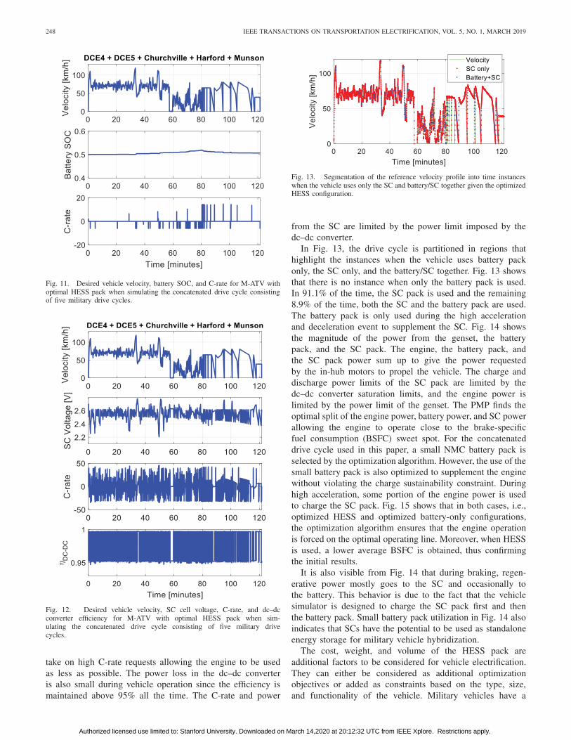
Fig. 11. Desired vehicle velocity, battery SOC, and C-rate for M-ATV withoptimal HESS pack when simulating the concatenated drive cycle consistingof five military drive cycles.
Fig. 12. Desired vehicle velocity, SC cell voltage, C-rate, and dc–dcconverter efficiency for M-ATV with optimal HESS pack when sim-ulating the concatenated drive cycle consisting of five military drivecycles.
take on high C-rate requests allowing the engine to be usedas less as possible. The power loss in the dc–dc converteris also small during vehicle operation since the efficiency ismaintained above 95% all the time. The C-rate and power
Fig. 13. Segmentation of the reference velocity profile into time instanceswhen the vehicle uses only the SC and battery/SC together given the optimizedHESS configuration.
from the SC are limited by the power limit imposed by thedc–dc converter.
In Fig. 13, the drive cycle is partitioned in regions thathighlight the instances when the vehicle uses battery packonly, the SC only, and the battery/SC together. Fig. 13 showsthat there is no instance when only the battery pack is used.In 91.1% of the time, the SC pack is used and the remaining8.9% of the time, both the SC and the battery pack are used.The battery pack is only used during the high accelerationand deceleration event to supplement the SC. Fig. 14 showsthe magnitude of the power from the genset, the batterypack, and the SC pack. The engine, the battery pack, andthe SC pack power sum up to give the power requestedby the in-hub motors to propel the vehicle. The charge anddischarge power limits of the SC pack are limited by thedc–dc converter saturation limits, and the engine power islimited by the power limit of the genset. The PMP finds theoptimal split of the engine power, battery power, and SC powerallowing the engine to operate close to the brake-specificfuel consumption (BSFC) sweet spot. For the concatenateddrive cycle used in this paper, a small NMC battery pack isselected by the optimization algorithm. However, the use of thesmall battery pack is also optimized to supplement the enginewithout violating the charge sustainability constraint. Duringhigh acceleration, some portion of the engine power is usedto charge the SC pack. Fig. 15 shows that in both cases, i.e.,optimized HESS and optimized battery-only configurations,the optimization algorithm ensures that the engine operationis forced on the optimal operating line. Moreover, when HESSis used, a lower average BSFC is obtained, thus confirmingthe initial results.
It is also visible from Fig. 14 that during braking, regen-erative power mostly goes to the SC and occasionally tothe battery. This behavior is due to the fact that the vehiclesimulator is designed to charge the SC pack first and thenthe battery pack. Small battery pack utilization in Fig. 14 alsoindicates that SCs have the potential to be used as standaloneenergy storage for military vehicle hybridization.
The cost, weight, and volume of the HESS pack areadditional factors to be considered for vehicle electrification.They can either be considered as additional optimizationobjectives or added as constraints based on the type, size,and functionality of the vehicle. Military vehicles have a
Authorized licensed use limited to: Stanford University. Downloaded on March 14,2020 at 20:12:32 UTC from IEEE Xplore. Restrictions apply.

MAMUN et al.: INTEGRATED DESIGN AND CONTROL OPTIMIZATION FRAMEWORK FOR HYBRID MILITARY VEHICLE 249
Fig. 14. Optimal power split among the genset, the battery pack, and the SCpack when simulating the series hybrid M-ATV simulator with an optimizedHESS configuration for the concatenated drive cycle.
Fig. 15. Engine operating points with the optimized battery-only and HESSconfiguration along with the engine BSFC contours for the concatenated cycle.The reduction in fuel consumption for HESS is obtained by shifting the engineoperating points toward the more efficient region with a lower average BSFC.
higher degree of flexibility in design compared to commercialvehicles, and therefore, these factors are excluded from thispaper. The proposed optimization algorithm is general enoughto incorporate those factors and is currently intended to beconsidered in future studies.
Remark: In this paper, the current and voltage limits of acommercially available dc–dc converter were used. It is knownthat the physical limits of the converter impose a limit on thepower delivered by the SC pack. A proper selection of thedc–dc converter through optimization or a customized dc–dc
converter based on the vehicle power requirement could allowthe SC to better utilize its available power capability.
V. CONCLUSION
This paper develops a novel mathematical framework forcombined design optimization and optimal energy manage-ment of a series HEV with an HESS. The key element ofthe proposed framework is in the formulation of the Hamil-tonian function, from the PMP strategy, to account for bothtime-varying control and design variables. The optimizationframework is implemented to minimize fuel consumption of anotional military HEV by finding the optimal sizes the Li-ionand SC pack and optimal power split among the genset, batterypack, and the SC pack. The key findings of this paper aresummarized below.
1) The simulation results show that for a concatenated drivecycle combining five military drive cycles, the optimaldesign and energy management algorithm can reduce thefuel consumption by nearly 7.3% for the battery-onlycase compared to the baseline.
2) When using the HESS configuration fuel consump-tion is reduced by up to 13% compared to thebaseline.
3) The optimal pack size of the HESS configura-tion shows that the contribution of Li-ion batterypack is not significant if there is a properly sizedSC available in the HESS configuration. Therefore,there is a high potential for using SCs for militaryvehicle hybridization even as a standalone storagesystem.
The future work aims at extending the proposed optimizationalgorithm to tackle multiple objectives such as battery healthdegradation, the lifecycle cost of the ESS. Active temperaturecontrol of the battery pack to prevent thermal runway andtemperature related aging effects is also a part of the futurework as well as the extension of the proposed framework toPHEVs and electric vehicles.
DISCLAIMER
Unclassified. DISTRIBUTION STATEMENT A. Approvedfor public release; distribution is unlimited.
Reference herein to any specific commercial company,product, process, or service by trade name, trademark, manu-facturer, or otherwise does not necessarily constitute or implyits endorsement, recommendation, or favoring by the UnitedStates Government or the Dept. of the Army (DoA). Theopinions of the authors expressed herein do not necessarilystate or reflect those of the United States Government orthe DoD, and shall not be used for advertising or productendorsement purposes.
REFERENCES
[1] Z. Filipi et al., “Engine-in-the-loop testing for evaluating hybrid propul-sion concepts and transient emissions—HMMWV case study,” SAETrans., vol. 115, pp. 23–41, Jan. 2006.
[2] D. M. Kramer and G. G. Parker, “Current state of military hybrid vehicledevelopment,” Int. J. Electr. Hybrid Vehicles, vol. 3, no. 4, pp. 369–387,2011.
Authorized licensed use limited to: Stanford University. Downloaded on March 14,2020 at 20:12:32 UTC from IEEE Xplore. Restrictions apply.

250 IEEE TRANSACTIONS ON TRANSPORTATION ELECTRIFICATION, VOL. 5, NO. 1, MARCH 2019
[3] D. M. Rizzo, “Military vehicle optimization and control,” M.S. thesis,Dept. Mech. Eng.-Eng. Mech., Michigan Technol. Univ., Houghton, MI,USA, 2014.
[4] J. Li et al., “Toward low-cost, high-energy density, and high-powerdensity lithium-ion batteries,” J. Minerals, Met. Mater. Soc., vol. 69,no. 9, pp. 1484–1496, 2017.
[5] A. Santucci, A. Sorniotti, and C. Lekakou, “Power split strategies forhybrid energy storage systems for vehicular applications,” J. PowerSour., vol. 258, pp. 395–407, Jul. 2014.
[6] Z. Song et al., “Multi-objective optimization of a semi-active bat-tery/supercapacitor energy storage system for electric vehicles,” Appl.Energy, vol. 135, pp. 212–224, Dec. 2014.
[7] J. Cao and A. Emadi, “A new battery/ultracapacitor hybrid energystorage system for electric, hybrid, and plug-in hybrid electric vehicles,”IEEE Trans. Power Electron., vol. 27, no. 1, pp. 122–132, Jan. 2012.
[8] A. Barré, F. Suard, M. Gérard, and D. Riu, “Electric vehicles per-formance estimation through a patterns extraction and classificationmethodology,” J. Power Sources, vol. 273, pp. 670–679, Jan. 2015.
[9] Z. Liu, S. Onori, and A. Ivanco, “Synthesis and experimental validationof battery aging test profiles based on real-world duty cycles for 48-V mild hybrid vehicles,” IEEE Trans. Veh. Technol., vol. 66, no. 10,pp. 8702–8709, Oct. 2017.
[10] Z. Song, H. Hofmann, J. Li, X. Han, and M. Ouyang, “Optimizationfor a hybrid energy storage system in electric vehicles using dynamicprograming approach,” Appl. Energy, vol. 139, pp. 151–162, Feb. 2015.
[11] E. Schaltz, A. Khaligh, and P. O. Rasmussen, “Influence of bat-tery/ultracapacitor energy-storage sizing on battery lifetime in a fuelcell hybrid electric vehicle,” IEEE Trans. Veh. Technol., vol. 58, no. 8,pp. 3882–3891, Oct. 2009.
[12] O. Erdinc and M. Uzunoglu, “Optimum design of hybrid renewableenergy systems: Overview of different approaches,” Renew. Sustain.Energy Rev., vol. 16, no. 3, pp. 1412–1425, 2012.
[13] S. M. Lukic, S. G. Wirasingha, F. Rodriguez, J. Cao, and A. Emadi,“Power management of an ultracapacitor/battery hybrid energy storagesystem in an HEV,” in Proc. IEEE Vehicle Power Propuls. Conf. (VPPC),Sep. 2006, pp. 1–6.
[14] Z. Song, J. Hou, H. Hofmann, J. Li, and M. Ouyang, “Sliding-modeand Lyapunov function-based control for battery/supercapacitor hybridenergy storage system used in electric vehicles,” Energy, vol. 122,pp. 601–612, Mar. 2017.
[15] P. Thounthong, S. Raël, and B. Davat, “Energy management of fuelcell/battery/supercapacitor hybrid power source for vehicle applications,”J. Power Sour., vol. 193, no. 1, pp. 376–385, 2009.
[16] M. Zolot, “Dual-source energy storage-control and performance advan-tages in advanced vehicles,” in Proc. 20th Electr. Vehicle Symp., 2003.
[17] Z. Yu, D. Zinger, and A. Bose, “An innovative optimal power allocationstrategy for fuel cell, battery and supercapacitor hybrid electric vehicle,”J. Power Sources, vol. 196, no. 4, pp. 2351–2359, 2011.
[18] A. Mirhoseini and F. Koushanfar, “HypoEnergy. Hybrid supercapacitor-battery power-supply optimization for energy efficiency,” in Proc.Design, Automat. Test Eur. Conf. Exhib. (DATE), Mar. 2011, pp. 1–4.
[19] E. Vinot and R. Trigui, “Optimal energy management of HEVswith hybrid storage system,” Energy Convers. Manage., vol. 76,pp. 437–452, Dec. 2013.
[20] A. Nguyen, J. Lauber, and M. Dambrine, “Optimal control based algo-rithms for energy management of automotive power systems with bat-tery/supercapacitor storage devices,” Energy Convers. Manage., vol. 87,pp. 410–420, Nov. 2014.
[21] S. Zhang, R. Xiong, and F. Sun, “Model predictive control for powermanagement in a plug-in hybrid electric vehicle with a hybrid energystorage system,” Appl. Energy, vol. 185, pp. 1654–1662, Jan. 2017.
[22] S. Onori and L. Tribioli, “Adaptive pontryagin’s minimum principlesupervisory controller design for the plug-in hybrid GM chevrolet volt,”Appl. Energy, vol. 147, pp. 224–234, Jun. 2015.
[23] M. Jain, C. Desai, and S. S. Williamson, “Genetic algorithm basedoptimal powertrain component sizing and control strategy design for afuel cell hybrid electric bus,” in Proc. IEEE Veh. Power Propuls. Conf.,Sep. 2009, pp. 980–985.
[24] M. Masih-Tehrani, M.-R. Ha’iri-Yazdi, V. Esfahanian, and A. Safaei,“Optimum sizing and optimum energy management of a hybrid energystorage system for lithium battery life improvement,” J. Power Sources,vol. 244, pp. 2–10, Dec. 2013.
[25] X. Hu, N. Murgovski, L. M. Johannesson, and B. Egardt,“Comparison of three electrochemical energy buffers applied to a hybridbus powertrain with simultaneous optimal sizing and energy manage-ment,” IEEE Trans. Intell. Transp. Syst., vol. 15, no. 3, pp. 1193–1205,Jun. 2014.
[26] X. Hu, L. Johannesson, N. Murgovski, and B. Egardt, “Longevity-conscious dimensioning and power management of the hybrid energystorage system in a fuel cell hybrid electric bus,” Appl. Energy, vol. 137,pp. 913–924, Jan. 2015.
[27] T. Donateo, L. Serrao, and G. Rizzoni, “A two-step optimisation methodfor the preliminary design of a hybrid electric vehicle,” Int. J. Electr.Hybrid Vehicles, vol. 1, no. 2, pp. 142–165, 2008.
[28] O. P. Sharma, S. Onori, and Y. Guezennec, “Analysis of Pontryagin’sminimum principle-based energy management strategy for PHEV appli-cations,” in Proc. ASME 5th Annu. Dyn. Syst. Control Conf., Joint JSME11th Motion Vib. Conf., 2012, pp. 145–150.
[29] Multi-Mission Family of Vehicles M-ATV, Oshkosh Defense, Temecula,CA, USA, 2016.
[30] Y. Kim, A. Salvi, J. B. Siegel, Z. S. Filipi, A. G. Stefanopoulou,and T. Ersal, “Hardware-in-the-loop validation of a power manage-ment strategy for hybrid powertrains,” Control Eng. Pract., vol. 29,pp. 277–286, Aug. 2014.
[31] Z. Liu, A. Mamun, and S. Onori, “Combined battery design optimizationand energy management of a series hybrid military truck,” SAE Int.J. Altern. Powertrains, to be published.
[32] X. Lin et al., “A lumped-parameter electro-thermal model for cylindricalbatteries,” J. Power Sour., vol. 257, pp. 1–11, Jul. 2014.
[33] S. Fiorenti, J. Guanetti, Y. Guezennec, and S. Onori, “Modeling andexperimental validation of a hybridized energy storage system for auto-motive applications,” J. Power Sour., vol. 241, pp. 112–120, Nov. 2013.
[34] Maxwell Technologies. Datasheet-K2 Ultracapacitors. [Online].Available: http://www.maxwell.com/images/documents/K2Series_DS_1015370_5_20141104.pdf
[35] R. W. Erikson and D. Maksimovic, Fundamentals of Power Electronics.Norwell, MA, USA: Kluwer, 2001.
[36] J. Shen and A. Khaligh, “A supervisory energy management con-trol strategy in a battery/ultracapacitor hybrid energy storage sys-tem,” IEEE Trans. Transport. Electrific., vol. 1, no. 3, pp. 223–231,Oct. 2015.
[37] SINAMICS DCP—The Innovative DC–DC Converter for Industry andthe Smart Grid, Siemens Ind. Inc., Munich, Germany, 2016.
[38] R. W. Erickson, “DC–DC power converters,” in Wiley Encyclopediaof Electrical and Electronics Engineering, vol. 1. Hoboken, NJ, USA:Wiley, 2001, no. 1, pp. 1–19.
[39] S. Onori, L. Serrao, and G. Rizzoni, Hybrid Electric Vehicles: EnergyManagement Strategies. London, U.K.: Springer, 2016.
[40] R. Hassan, B. Cohanim, O. de Weck, and G. Venter, “A comparison ofparticle swarm optimization and the genetic algorithm,” in Proc. 46thAIAA/ASME/ASCE/AHS/ASC Struct., Struct. Dyn. Mater. Conf., 2005,p. 1897.
[41] Vehicle Test Facilities, Aberdeen Test Center, Yuma Test Center,Aberdeen, MD, USA, 1995.
Abdullah-Al Mamun received the B.Sc. and M.Sc.degrees from the Department of Industrial andProduction Engineering, Bangladesh University ofEngineering and Technology, Dhaka, Bangladesh,in 2009 and 2011, respectively, and the Ph.D. degreefrom the Department of Mechanical Engineering,Pennsylvania State University, State College, PA,USA, in 2017.
He is currently a Post-Doctoral Fellow with theDepartment of Automotive Engineering, ClemsonUniversity, Greenville, SC, USA. His current
research interests include lithium-ion battery modeling and control, hybridvehicle design and energy management, physics-based modeling, and controlof three-way catalyst.
Authorized licensed use limited to: Stanford University. Downloaded on March 14,2020 at 20:12:32 UTC from IEEE Xplore. Restrictions apply.

MAMUN et al.: INTEGRATED DESIGN AND CONTROL OPTIMIZATION FRAMEWORK FOR HYBRID MILITARY VEHICLE 251
Zifan Liu received the B.S. degree in automo-tive engineering from Jilin University, Changchun,China, in 2012, and the Ph.D. degree in automotiveengineering from Clemson University, Greenville,SC, USA, in 2016.
From 2017 to 2018, he was a Post-Doctoral Fellowwith the Clemson University International Center forAutomotive Research, Greenville, SC, USA. He iscurrently an Engineer with Bosch Rexroth, FountainInn, SC, USA. His current research interests includepopulation naturalistic driving data analysis, dynam-
ics modeling, optimal design and control.
Denise M. Rizzo received the Ph.D. degree fromMichigan Technological University, Houghton, MI,USA, in 2014.
From 2000 to 2008, she was a Controls Researchand Development Engineer with Chrysler LLC,Auburn Hills, MI, USA. In 2008, she joined the U.S.Army Tank Automotive Research, Development, andEngineering Center, Warren, MI, USA, where sheis currently a Senior Research Mechanical Engineerwith the Powertrain Modeling and Simulation Team.She specializes in modeling, simulation, and control
of propulsion systems of ground vehicles. She has authored or co-authored15 articles in archival journals, 29 papers in refereed conference proceedings,and 4 technical government reports. She holds two patents.
Simona Onori (SM’15) received the Laurea degree(summa cum laude) in computer science engineeringfrom the University of Rome Tor Vergata, Rome,Italy, in 2003, the M.S. degree in electrical andcomputer engineering from the University of NewMexico, Albuquerque, NM, USA, in 2004, and thePh.D. degree in control engineering from the Uni-versity of Rome Tor Vergata, in 2007.
Since 2017, she has been an Assistant Professorwith the Energy Resources Engineering Department,Stanford University, Stanford, CA, USA.
Dr. Onori was a recipient of the SAE Ralph R. Teetor Educational Award,the 2017 NSF CAREER Award, the 2017 Clemson University College ofEngineering and Science Dean’s Faculty Fellows Award, the 2017 ClemsonUniversity Esin Gulari Leadership and Service Award, the 2016 EnergyLeadership Award in the category Emerging Leader (for the Carolinas), andthe 2015 Innovision Award (SC, USA).
Authorized licensed use limited to: Stanford University. Downloaded on March 14,2020 at 20:12:32 UTC from IEEE Xplore. Restrictions apply.