Embed Size (px)
Citation preview
Scientific Research and Essay Vol.4 (10), pp. 1109-1116, October 2009 Available online at http://www.academicjournals.org/SRE ISSN 1992-2248 © 2009 Academic Journals Full Length Research paper
An optimise drilling process for an aircraft composite structure using design of experiments
M. K. A Mohd Ariffin1*, M. I. Mohd Ali2, S. M. Sapuan3 and N. Ismail4
Faculty of Engineering, Department of Mechanical and Manufacturing Engineering, Universiti Putra Malaysia, 43400
UPM, Serdang Selangor, Malaysia.
Accepted 21 July, 2009
The present work is focusing on an optimisation of the drilling cutting process for the composite sandwich panel. The study provided machinist with a simple procedure in order to minimise the damage events occurring during drilling process for composite material. A statistical approach is used to analyse the experiment data and it is called as design of experiment (DOE). The technique minimise the number of test required and maximizes the amount of reliable information. A glass fiber reinforced plastic (GFRP) sandwich part number of BMS 4 - 17 form Boeing corporation is used for testing. There are 2 type of drill bit material were selected and 4 variable such as drill bit material, cutting velocity, feed rate and hole diameter. The results from this study shows that the minimum damage length is 0.05 mm and the maximum is 0.44 mm which are done at 3000 rpm, feed rate of 80.2 mm/rev for HSS and spindle speed at 500 rpm, feed rate of 246.8 mm/rev using carbide tool respectively. Key words: Composite, drilling, design of experiment, optimization.
INTRODUCTION The making of an aerospace part has evolved from metallic components to composite material. The composite material is an ideal replacement material for the structures of the aerospace due to the light weight characteristics (Armstrong and Barrett, 1998). New development in the material technology has introduced a new puzzle such as how to machine this material. Numerous number of non-traditional machining processes such as water jet cutting, laser cutting, electro discharge machining (EDM) and ultrasonic cutting have been developed for machining holes for composite material (Chandrasekharan et al., 1995).
However the traditional method is still significant. Drilling is most frequently operation done, as building an aircraft definitely required an assembly. Numerous re-searches have studied in the delamination during drilling process (Chen, 1997; Davim and Reis, 2003; Khashaba, 2004; Tsao and Hocheng, 2004) but a few on the surface damage of the hole (Lachaud et al., 2001; Jung et al., 2005). Therefore in this present study a technique called design of experiment (DOE) is used as a tool to optimize *Corresponding author. E-mail: [email protected].
the cutting parameters during the cutting process. This process has been used by Boeing corporation in order to reduce costs during designing and testing process. Drilling composite Drilling is a process of making holes and it is essential for assembly especially related to the mechanical fasteners. In aircraft industries the drilling of the composite material is carried out for purpose of joining using rivet and bolt technique. As this procedure is important for aircraft structures, a great deal of research has been conducted in this area such as by (Bennet, 1985; Ramulu et al., 2001). It is obvious that drilling composite materials would be different if compared to the traditional method such as for drilling metals.
The failures for drilling composite can be classified as fiber breakout, delamination and fracture and the most critical was delamination around the drill hole. These mechanical failures contribute 60% of all parts rejection during final assembly of an aircraft (Stone and Krishnamurthy, 1996) and also it has been recognised as one of the limiting factor of usage composite in the aircraft industries.
1110 Sci. Res. Essays
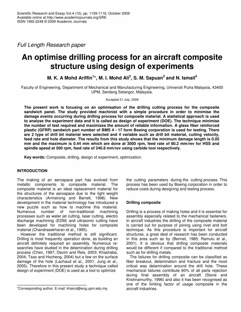
Figure 1. Detail inputs variable on drilling process.
Generally the delimination can be controlled by controlling drilling parameters such as tool geometry and tool material. For instance drilling with a high feed rate will cause a crack around the exit edge of the hole (Koenig et al., 1985). Therefore it is recommended that to use a high spindle speed and a slow feed rate for the drilling operation. Design of experiment Design of experiment (DOE) is a tool used to identify process regions that lead to superior product characteristics. This method identifies new regions for process operation and decrease variability within engineering tolerances, economic losses and can gain in the long terms. Generally, the process of designing new product involves a lot of experiments and testing and thus by using DOE, it minimises the number of test required and maximise the amount of reliable information gathered. This method uses a statistical approach rather then by ‘trial and error’ approach (Bingham, 1990).
In this project DOE was used to investigate the effects of drill materials and drilling process parameters such as cutting speed, feed rate and drill hole quality. These parameters are used for controlled parameters for both production and experimental environment and the humidity or ambient temperature is used for the uncontrolled parameters in DOE. A detail variable is summarised in Figure 1.
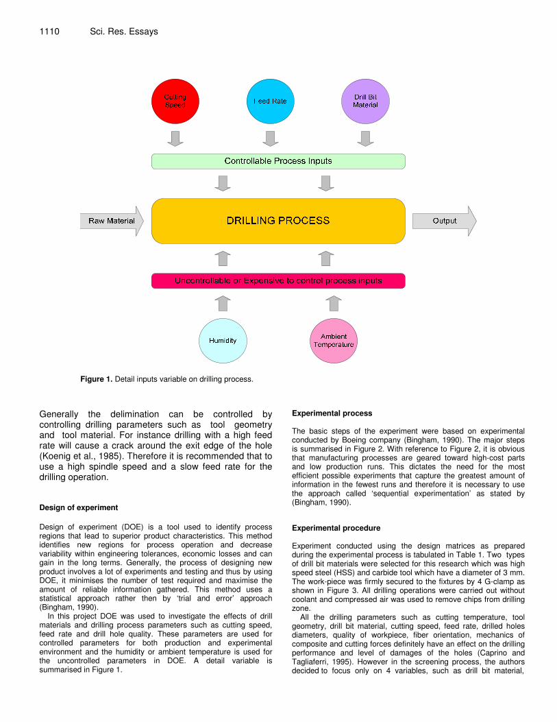
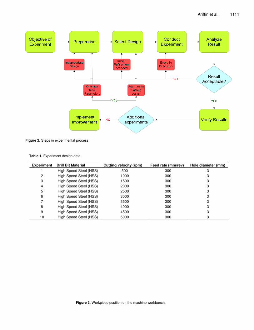
Experimental process The basic steps of the experiment were based on experimental conducted by Boeing company (Bingham, 1990). The major steps is summarised in Figure 2. With reference to Figure 2, it is obvious that manufacturing processes are geared toward high-cost parts and low production runs. This dictates the need for the most efficient possible experiments that capture the greatest amount of information in the fewest runs and therefore it is necessary to use the approach called ‘sequential experimentation’ as stated by (Bingham, 1990). Experimental procedure Experiment conducted using the design matrices as prepared during the experimental process is tabulated in Table 1. Two types of drill bit materials were selected for this research which was high speed steel (HSS) and carbide tool which have a diameter of 3 mm. The work-piece was firmly secured to the fixtures by 4 G-clamp as shown in Figure 3. All drilling operations were carried out without coolant and compressed air was used to remove chips from drilling zone.
All the drilling parameters such as cutting temperature, tool geometry, drill bit material, cutting speed, feed rate, drilled holes diameters, quality of workpiece, fiber orientation, mechanics of composite and cutting forces definitely have an effect on the drilling performance and level of damages of the holes (Caprino and Tagliaferri, 1995). However in the screening process, the authors decided to focus only on 4 variables, such as drill bit material,
Ariffin et al. 1111
�
Figure 2. Steps in experimental process.
Table 1. Experiment design data.
Experiment Drill Bit Material Cutting velocity (rpm) Feed rate (mm/rev) Hole diameter (mm) 1 High Speed Steel (HSS) 500 300 3 2 High Speed Steel (HSS) 1000 300 3 3 High Speed Steel (HSS) 1500 300 3 4 High Speed Steel (HSS) 2000 300 3 5 High Speed Steel (HSS) 2500 300 3 6 High Speed Steel (HSS) 3000 300 3 7 High Speed Steel (HSS) 3500 300 3 8 High Speed Steel (HSS) 4000 300 3 9 High Speed Steel (HSS) 4500 300 3 10 High Speed Steel (HSS) 5000 300 3
�
Figure 3. Workpiece position on the machine workbench.
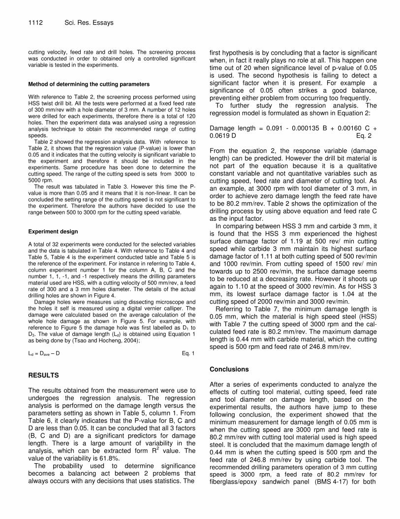
1112 Sci. Res. Essays cutting velocity, feed rate and drill holes. The screening process was conducted in order to obtained only a controlled significant variable is tested in the experiments. Method of determining the cutting parameters With reference to Table 2, the screening process performed using HSS twist drill bit. All the tests were performed at a fixed feed rate of 300 mm/rev with a hole diameter of 3 mm. A number of 12 holes were drilled for each experiments, therefore there is a total of 120 holes. Then the experiment data was analysed using a regression analysis technique to obtain the recommended range of cutting speeds.
Table 2 showed the regression analysis data. With reference to Table 2, it shows that the regression value (P-value) is lower than 0.05 and it indicates that the cutting velocity is significant variable to the experiment and therefore it should be included in the experiments. Same procedure has been done to determine the cutting speed. The range of the cutting speed is sets from 3000 to 5000 rpm.
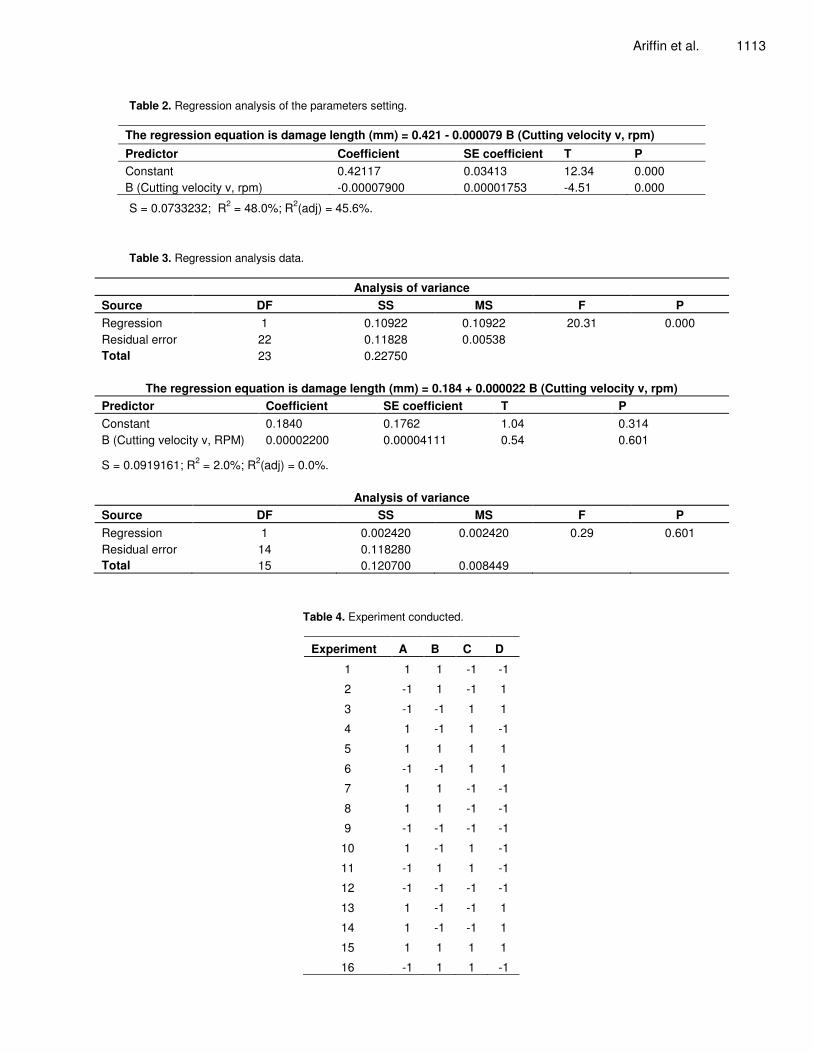
The result was tabulated in Table 3. However this time the P-value is more than 0.05 and it means that it is non-linear. It can be concluded the setting range of the cutting speed is not significant to the experiment. Therefore the authors have decided to use the range between 500 to 3000 rpm for the cutting speed variable. Experiment design A total of 32 experiments were conducted for the selected variables and the data is tabulated in Table 4. With reference to Table 4 and Table 5, Table 4 is the experiment conducted table and Table 5 is the reference of the experiment. For instance in referring to Table 4, column experiment number 1 for the column A, B, C and the number 1, 1, -1, and -1 respectively means the drilling parameters material used are HSS, with a cutting velocity of 500 mm/rev, a feed rate of 300 and a 3 mm holes diameter. The details of the actual drilling holes are shown in Figure 4.
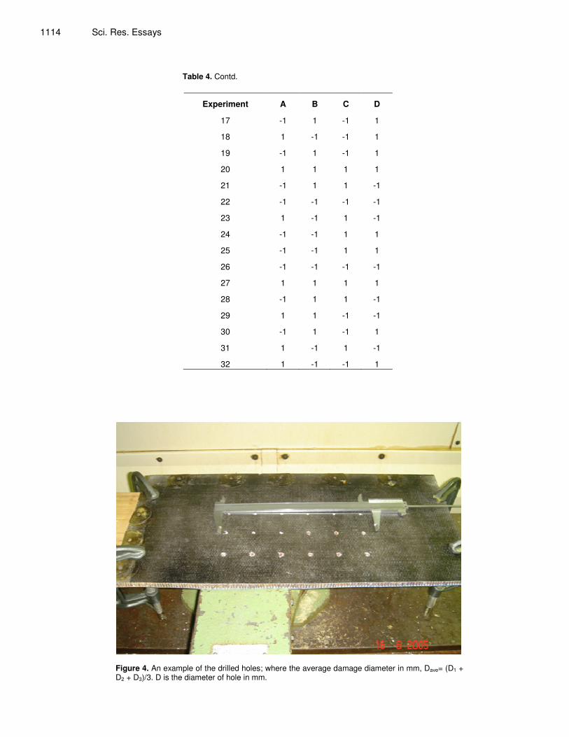
Damage holes were measures using dissecting microscope and the holes it self is measured using a digital vernier calliper. The damage were calculated based on the average calculation of the whole hole damage as shown in Figure 5. For example, with reference to Figure 5 the damage hole was first labelled as D1 to D3. The value of damage length (Ld) is obtained using Equation 1 as being done by (Tsao and Hocheng, 2004);
Ld = Dave – D Eq. 1 RESULTS The results obtained from the measurement were use to undergoes the regression analysis. The regression analysis is performed on the damage length versus the parameters setting as shown in Table 5, column 1. From Table 6, it clearly indicates that the P-value for B, C and D are less than 0.05. It can be concluded that all 3 factors (B, C and D) are a significant predictors for damage length. There is a large amount of variability in the analysis, which can be extracted form R2 value. The value of the variability is 61.8%.
The probability used to determine significance becomes a balancing act between 2 problems that always occurs with any decisions that uses statistics. The
first hypothesis is by concluding that a factor is significant when, in fact it really plays no role at all. This happen one time out of 20 when significance level of p-value of 0.05 is used. The second hypothesis is failing to detect a significant factor when it is present. For example a significance of 0.05 often strikes a good balance, preventing either problem from occurring too frequently.
To further study the regression analysis. The regression model is formulated as shown in Equation 2: Damage length = 0.091 - 0.000135 B + 0.00160 C + 0.0619 D Eq. 2 From the equation 2, the response variable (damage length) can be predicted. However the drill bit material is not part of the equation because it is a qualitative constant variable and not quantitative variables such as cutting speed, feed rate and diameter of cutting tool. As an example, at 3000 rpm with tool diameter of 3 mm, in order to achieve zero damage length the feed rate have to be 80.2 mm/rev. Table 2 shows the optimization of the drilling process by using above equation and feed rate C as the input factor.
In comparing between HSS 3 mm and carbide 3 mm, it is found that the HSS 3 mm experienced the highest surface damage factor of 1.19 at 500 rev/ min cutting speed while carbide 3 mm maintain its highest surface damage factor of 1.11 at both cutting speed of 500 rev/min and 1000 rev/min. From cutting speed of 1500 rev/ min towards up to 2500 rev/min, the surface damage seems to be reduced at a decreasing rate. However it shoots up again to 1.10 at the speed of 3000 rev/min. As for HSS 3 mm, its lowest surface damage factor is 1.04 at the cutting speed of 2000 rev/min and 3000 rev/min.
Referring to Table 7, the minimum damage length is 0.05 mm, which the material is high speed steel (HSS) with Table 7 the cutting speed of 3000 rpm and the cal-culated feed rate is 80.2 mm/rev. The maximum damage length is 0.44 mm with carbide material, which the cutting speed is 500 rpm and feed rate of 246.8 mm/rev. Conclusions After a series of experiments conducted to analyze the effects of cutting tool material, cutting speed, feed rate and tool diameter on damage length, based on the experimental results, the authors have jump to these following conclusion, the experiment showed that the minimum measurement for damage length of 0.05 mm is when the cutting speed are 3000 rpm and feed rate is 80.2 mm/rev with cutting tool material used is high speed steel. It is concluded that the maximum damage length of 0.44 mm is when the cutting speed is 500 rpm and the feed rate of 246.8 mm/rev by using carbide tool. The recommended drilling parameters operation of 3 mm cutting speed is 3000 rpm, a feed rate of 80.2 mm/rev for fiberglass/epoxy sandwich panel (BMS 4-17) for both
Ariffin et al. 1113
Table 2. Regression analysis of the parameters setting.
The regression equation is damage length (mm) = 0.421 - 0.000079 B (Cutting velocity v, rpm) Predictor Coefficient SE coefficient T P Constant 0.42117 0.03413 12.34 0.000 B (Cutting velocity v, rpm) -0.00007900 0.00001753 -4.51 0.000
S = 0.0733232; R2 = 48.0%; R2(adj) = 45.6%.
Table 3. Regression analysis data.
Analysis of variance Source DF SS MS F P Regression 1 0.10922 0.10922 20.31 0.000 Residual error 22 0.11828 0.00538 Total 23 0.22750
The regression equation is damage length (mm) = 0.184 + 0.000022 B (Cutting velocity v, rpm) Predictor Coefficient SE coefficient T P Constant 0.1840 0.1762 1.04 0.314 B (Cutting velocity v, RPM) 0.00002200 0.00004111 0.54 0.601
S = 0.0919161; R2 = 2.0%; R2(adj) = 0.0%.
Analysis of variance Source DF SS MS F P Regression 1 0.002420 0.002420 0.29 0.601 Residual error 14 0.118280 Total 15 0.120700 0.008449
Table 4. Experiment conducted.
Experiment A B C D
1 1 1 -1 -1
2 -1 1 -1 1
3 -1 -1 1 1
4 1 -1 1 -1
5 1 1 1 1
6 -1 -1 1 1
7 1 1 -1 -1
8 1 1 -1 -1
9 -1 -1 -1 -1
10 1 -1 1 -1
11 -1 1 1 -1
12 -1 -1 -1 -1
13 1 -1 -1 1
14 1 -1 -1 1
15 1 1 1 1
16 -1 1 1 -1
1114 Sci. Res. Essays �
�
Table 4. Contd.
Experiment A B C D
17 -1 1 -1 1
18 1 -1 -1 1
19 -1 1 -1 1
20 1 1 1 1
21 -1 1 1 -1
22 -1 -1 -1 -1
23 1 -1 1 -1
24 -1 -1 1 1
25 -1 -1 1 1
26 -1 -1 -1 -1
27 1 1 1 1
28 -1 1 1 -1
29 1 1 -1 -1
30 -1 1 -1 1
31 1 -1 1 -1
32 1 -1 -1 1
Figure 4. An example of the drilled holes; where the average damage diameter in mm, Dave= (D1 + D2 + D3)/3. D is the diameter of hole in mm.
Ariffin et al. 1115
Figure 5. Drilled hole result and diameter calculation.
Table 5. Reference input factor.
Code Input factor Level 1 (+) Level 2 (-)
A Drill bit material High speed steel (HSS) Carbide
B Cutting velocity (rpm) 500 3000
C Feed rate (mm/rev) 50 300
D Hole diameter (mm) 6 3
Table 6. Regression analysis: Damage length versus B,C,D. Predictor Coefficient SE coefficient T P
Constant 0.0909 0.1539 0.59 0.560
B -0.00013525 0.00003301 -4.10 0.000
C 0.0015975 0.0003301 4.84 0.000
D 0.06188 0.02751 2.25 0.033
S = 0.233396; R-Sq = 61.8%; R-Sq (adj) = 57.7%
Table 7. Actual results of optimized feed rate for damage length = 0.
Tool material Cutting speed (rpm) Diameter (mm) Calculated feed rate, (mm/rev) Damage Length, average(mm)
High speed steel 3000 3 80.2 0.05
High speed steel 500 3 130.8 0.08 High speed steel 3000 6 40.0 0.10 High speed steel 500 6 246.8 0.12 Carbide 3000 3 80.2 0.06 Carbide 500 3 130.8 0.25
Carbide 3000 6 40.0 0.16
Carbide 500 6 246.8 0.44
1116 Sci. Res. Essays HSS and carbide.
Interaction between cutting speed and feed rate are the most significant in controlling the level of damage during drilling process. On the other hand, the interaction of cutting tool material and cutting speed are the most insignificant.
It is recommended that for future work, other parameter such as machining forces (thrust force and torque), acoustics emission, vibrations and temperatures should be consider for experiments. High range of cutting velocity from 3000 rpm and above should also be tested. The usage of special drill bits with different angles should also be taking into consideration towards minimum damage drilled holes. REFERENCES Armstrong KB, Barrett RT (1998). Care and repair of advanced
composites. Warrendale, Pa., Society of Automotive Engineers. Bennet BA (1985). Carbon-fiber composite: A light weight alternative.
Mechanical Engineering. p. 34. Bingham T (1990). Quality Breakthrough- A Boeing Commercial
Airplane Group Publication for Boeing Suppliers. p. 12. Caprino G, Tagliaferri V (1995). Damage development in drilling glass
fibre reinforced plastics." Int. J. Mach. Tools Manuf. 35(6): 817-829.
Chandrasekharan V, Kapoor SG, Devor RE (1995). A mechanistic
approach to predicting the cutting force in drilling: with application to fiber-reinforced composite materials. J. Eng. Ind. 117: 559-570.
Chen WI (1997). Some experimental investigations in the drilling of carbon fibre-reinforced plastics (CFRP) complete laminates." Int. J. Mach. Tools Manuf. 37(8): 1097-1018.
Davim JP, Reis P (2003). Drilling carbon fiber reinforced plastics manufactured by autoclave-experimental and statistical study. Materials Design 24: 315-324.
Jung JP, Kim GW, Lee KY (2005). Critical thrust force at delamination propagation during drilling of angle-ply laminates. Composites Structures 68: 391-397.
Khashaba UA (2004). Delamination in drilling GFR-thermoset compo-sites. Composites Structures 63: 313-327.
Koenig W, Wulf C, Grass P, Willerscheid H (1985). Machining of fiber reinforces plastics. Manuf. Tech. CIRP Ann., 34(2): 537-548.
Lachaud F, Piquet R, Collombet F, Surcin L (2001). Drilling of composite structures. Composite Structures 52: 511-516.
Ramulu M, Branson T, Kim D (2001). A study on the drilling of composite and titanium stacks. Composite Structures 54: 67-77.
Stone R, Krishnamurthy K (1996). A neural network thrust force controller to minimize delamination during drilling of graphite-epoxy laminates. J. Mach. Tools Manuf. 36(9): 985-1003.
Tsao CC, Hocheng HI (2004). Taguchi analysis of delamination associated with various drill bits in drilling of composite material. Int. J. Mach. Tools Manuf. 44: 1085-1090.