Embed Size (px)
Citation preview
er
Analog Input and OutputIntroduction
To move one step closer to creating real-time DSP applications,we now consider interfacing to the A/D–D/A subsystem that isincluded with the OMAP-L138 Experimenter. The discussionpresented here will focus on using the onboard analog interfacecircuit (AIC), i.e., TLV320AIC3106 denoted as AIC3106
Analog I/O Basics
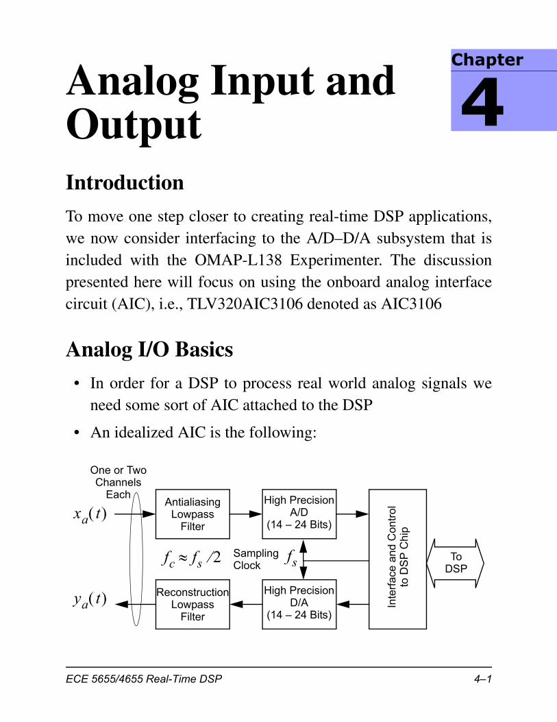
• In order for a DSP to process real world analog signals weneed some sort of AIC attached to the DSP
• An idealized AIC is the following:
AntialiasingLowpass
Filter
High PrecisionA/D
(14 – 24 Bits)
Inte
rfac
e an
d C
ontr
olto
DS
P C
hip
ReconstructionLowpass
Filter
High PrecisionD/A
(14 – 24 Bits)
xa t
ya t
SamplingClock
fs ToDSP
fc fs 2
One or TwoChannels
Each
Chapt
4
ECE 5655/4655 Real-Time DSP 4–1
Chapter 4 • Analog Input and Output
• As with any lowpass sampling theory system, the analoginput must not contain any frequency content above the fold-ing frequency, which in this case is
– To prevent aliasing and keep unwanted noise out of thesystem, an antialiasing filter is typically employed
– For the case of an ideal antialiasing filter, the cutoff fre-quency is
• The output analog signal as obtained from the D/A is post fil-tered with a lowpass reconstruction filter to remove spectraltranslates that exist at frequencies above
• Again thinking in terms of an ideal AIC, we would like tohave:
– Software control of the sampling rate, possibly asynchro-nous sampling rates at the A/D and D/A
– Software control of the input filter cutoff frequency (lowend and high end if a bandpass filter is also available, aselectable dc coupled input for certain control applications
– Software control of the reconstruction filter cutoff fre-quency
• A more general AIC should also provide two dedicatedinputs and two dedicated outputs, e.g., a stereo audio codec(CODer/DECoder)
– Most stereo audio codecs are at least 16-bits with samplingrates up to 44.1 or 48 kHz supported
fs 2
fc fs 2=
fs 2
4–2 ECE 5655/4655 Real-Time DSP
Analog I/O on the C6x
Analog I/O on the C6x
• For the C6x to interface with any form of analog I/O, e.g., A/D and D/A converters, we need to understand a little bit aboutinterrupt data processing and the use of the Multichannelaudio serial port (McASP)
• From a programming standpoint, the basics of interrupt ser-vice routines (ISRs), and maintaining real-time
• A side issue is the possible use of one of the C6x timers toobtain a programmable sampling rate clock
– An externally supplied sampling rate clock is also possible
Interrupt Basics
• As the name implies, the processor is halted from its normalprocessing, and required to execute an ISR
• The interrupt time-line is as follows:
– Configure: The programmer selects sources and creates aninterrupt vector table
– Enable: The programmer enables individual interrupts andenables the global interrupt
– CPU: Automatically takes care of seeing if a valid inter-rupt signal exists, setting a flag bit, and if the interrupt isenabled, branching to the appropriate ISR
– ISR Routine: Written by the programmer in C or assem-bly (here we are most interested in using C)
ECE 5655/4655 Real-Time DSP 4–3
Chapter 4 • Analog Input and Output
Source Selection on the OMAP-L138
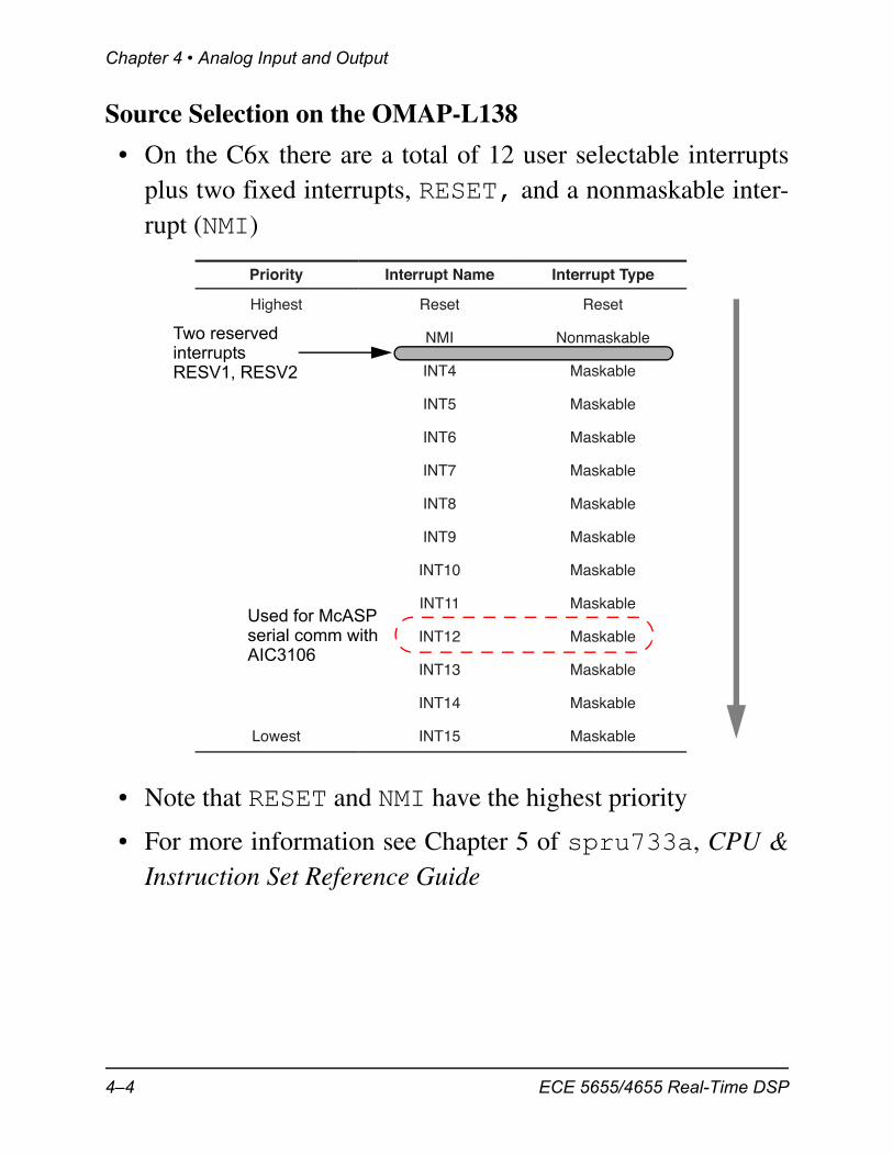
• On the C6x there are a total of 12 user selectable interruptsplus two fixed interrupts, RESET, and a nonmaskable inter-rupt (NMI)
• Note that RESET and NMI have the highest priority
• For more information see Chapter 5 of spru733a, CPU &Instruction Set Reference Guide
Priority Interrupt Name Interrupt Type
Highest Reset Reset
NMI Nonmaskable
INT4 Maskable
INT5 Maskable
INT6 Maskable
INT7 Maskable
INT8 Maskable
INT9 Maskable
INT10 Maskable
INT11 Maskable
INT12 Maskable
INT13 Maskable
INT14 Maskable
Lowest INT15 Maskable
Used for McASPserial comm withAIC3106
Two reservedinterruptsRESV1, RESV2
4–4 ECE 5655/4655 Real-Time DSP
Analog I/O on the C6x
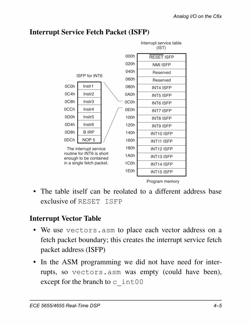
Interrupt Service Fetch Packet (ISFP)
• The table itself can be reolated to a different address baseexclusive of RESET ISFP
Interrupt Vector Table
• We use vectors.asm to place each vector address on afetch packet boundary; this creates the interrupt service fetchpacket address (ISFP)
• In the ASM programming we did not have need for inter-rupts, so vectors.asm was empty (could have been),except for the branch to c_int00
Instr3
Interrupt service table(IST)
Instr2
Instr4
Instr5
Instr6
B IRP
NOP 5
ISFP for INT6
000h
020h
040h
060h
080h
0A0h
0C0h
0E0h
100h
120h
140h
160h
180h
1A0h
1C0h
1E0h
0C0h
0C4h
0C8h
0CCh
0D0h
0D4h
0D8h
0DCh
The interrupt serviceroutine for INT6 is shortenough to be containedin a single fetch packet.
Program memory
RESET ISFP
NMI ISFP
Reserved
Reserved
INT4 ISFP
INT5 ISFP
INT6 ISFP
INT7 ISFP
INT8 ISFP
INT9 ISFP
INT10 ISFP
INT11 ISFP
INT12 ISFP
INT13 ISFP
INT14 ISFP
INT15 ISFP
Instr1
ECE 5655/4655 Real-Time DSP 4–5
Chapter 4 • Analog Input and Output
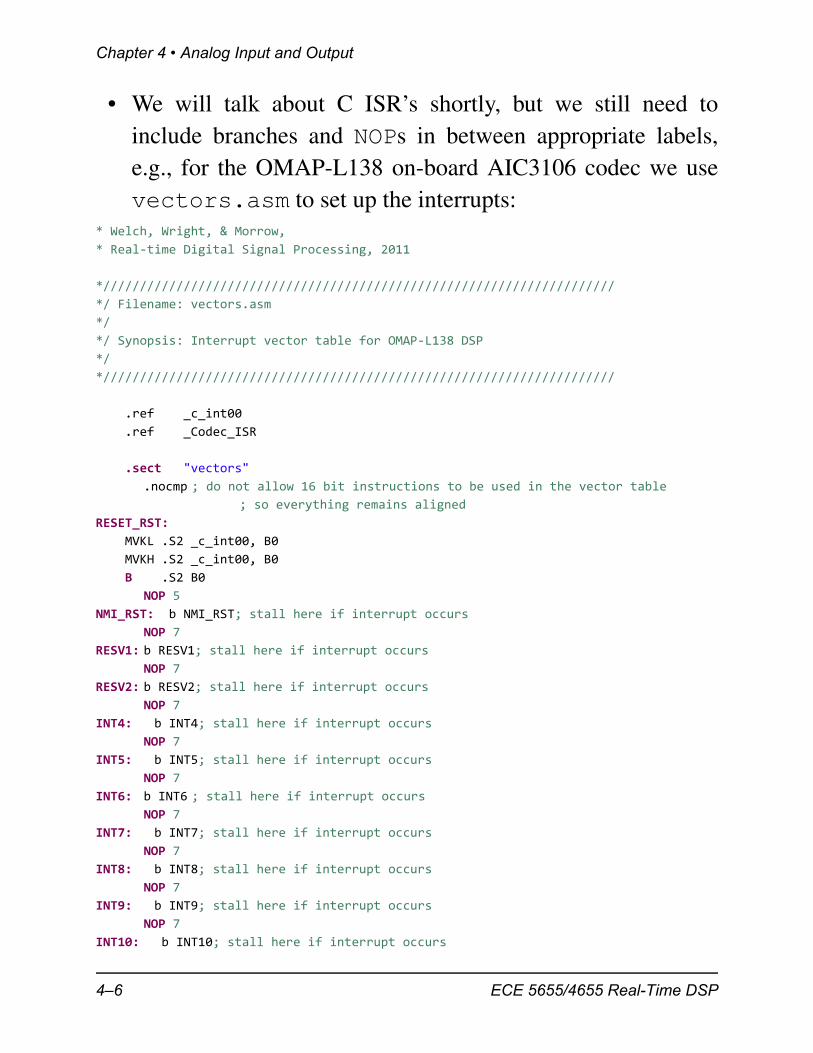
• We will talk about C ISR’s shortly, but we still need toinclude branches and NOPs in between appropriate labels,e.g., for the OMAP-L138 on-board AIC3106 codec we usevectors.asm to set up the interrupts:
* Welch, Wright, & Morrow,
* Real‐time Digital Signal Processing, 2011
*//////////////////////////////////////////////////////////////////////
*/ Filename: vectors.asm
*/
*/ Synopsis: Interrupt vector table for OMAP‐L138 DSP
*/
*//////////////////////////////////////////////////////////////////////
.ref _c_int00
.ref _Codec_ISR
.sect "vectors"
.nocmp ; do not allow 16 bit instructions to be used in the vector table
; so everything remains aligned
RESET_RST:
MVKL .S2 _c_int00, B0
MVKH .S2 _c_int00, B0
B .S2 B0
NOP 5
NMI_RST: b NMI_RST; stall here if interrupt occurs
NOP 7
RESV1: b RESV1; stall here if interrupt occurs
NOP 7
RESV2: b RESV2; stall here if interrupt occurs
NOP 7
INT4: b INT4; stall here if interrupt occurs
NOP 7
INT5: b INT5; stall here if interrupt occurs
NOP 7
INT6: b INT6 ; stall here if interrupt occurs
NOP 7
INT7: b INT7; stall here if interrupt occurs
NOP 7
INT8: b INT8; stall here if interrupt occurs
NOP 7
INT9: b INT9; stall here if interrupt occurs
NOP 7
INT10: b INT10; stall here if interrupt occurs
4–6 ECE 5655/4655 Real-Time DSP
Analog I/O on the C6x
NOP 7
INT11: b INT11; stall here if interrupt occurs
NOP 7
INT12: b _Codec_ISR
NOP 7
INT13: b INT13; stall here if interrupt occurs
NOP 7
INT14: b INT14; stall here if interrupt occurs
NOP 7
INT15: b INT15; stall here if interrupt occurs
NOP 7
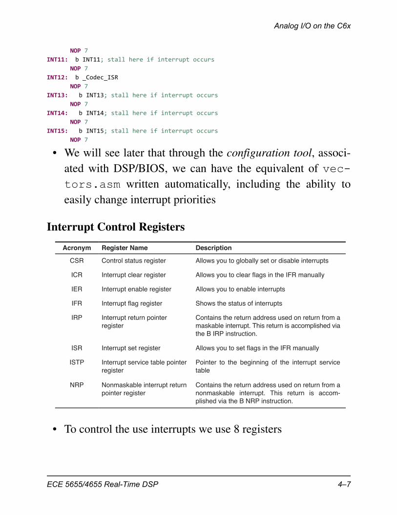
• We will see later that through the configuration tool, associ-ated with DSP/BIOS, we can have the equivalent of vec-tors.asm written automatically, including the ability toeasily change interrupt priorities
Interrupt Control Registers
• To control the use interrupts we use 8 registers
Acronym Register Name Description
CSR Control status register Allows you to globally set or disable interrupts
ICR Interrupt clear register Allows you to clear flags in the IFR manually
IER Interrupt enable register Allows you to enable interrupts
IFR Interrupt flag register Shows the status of interrupts
IRP Interrupt return pointerregister
Contains the return address used on return from amaskable interrupt. This return is accomplished viathe B IRP instruction.
ISR Interrupt set register Allows you to set flags in the IFR manually
ISTP Interrupt service table pointerregister
Pointer to the beginning of the interrupt servicetable
NRP Nonmaskable interrupt returnpointer register
Contains the return address used on return from anonmaskable interrupt. This return is accom-plished via the B NRP instruction.
ECE 5655/4655 Real-Time DSP 4–7
Chapter 4 • Analog Input and Output
Enabling Interrupts
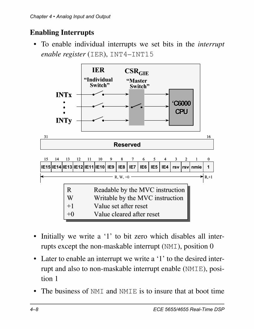
• To enable individual interrupts we set bits in the interruptenable register (IER), INT4–INT15
• Initially we write a ‘1’ to bit zero which disables all inter-rupts except the non-maskable interrupt (NMI), position 0
• Later to enable an interrupt we write a ‘1’ to the desired inter-rupt and also to non-maskable interrupt enable (NMIE), posi-tion 1
• The business of NMI and NMIE is to insure that at boot time
INTxINTx
INTyINTy
IERIER“Individual“Individual
Switch”Switch”
CSRCSRGIEGIE“Master“Master
Switch”Switch”
‘C6000‘C6000CPUCPU
INTxINTx
INTyINTy
IERIER“Individual“Individual
Switch”Switch”
CSRCSRGIEGIE“Master“Master
Switch”Switch”
‘C6000‘C6000CPUCPU
nmienmie 11rsvrsvrsvrsvIE4IE4IE5IE5IE6IE6IE7IE7IE8IE8IE9IE9IE10IE10IE11IE11IE12IE12IE13IE13IE14IE14IE15IE15
1515 1414 1313 1212 1111 1010 99 88 77 66 55 44 33 22 11 00
3131 1616
ReservedReserved
R, W, +0R, W, +0 R,+1R,+1
nmienmie 11rsvrsvrsvrsvIE4IE4IE5IE5IE6IE6IE7IE7IE8IE8IE9IE9IE10IE10IE11IE11IE12IE12IE13IE13IE14IE14IE15IE15
1515 1414 1313 1212 1111 1010 99 88 77 66 55 44 33 22 11 00
3131 1616
ReservedReserved
R, W, +0R, W, +0R, W, +0R, W, +0 R,+1R,+1
R Readable by the MVC instructionW Writable by the MVC instruction+1 Value set after reset+0 Value cleared after reset
RR Readable by the MVC instructionReadable by the MVC instructionWW Writable by the MVC instructionWritable by the MVC instruction+1+1 Value set after resetValue set after reset+0 +0 Value cleared after resetValue cleared after reset
4–8 ECE 5655/4655 Real-Time DSP
Analog I/O on the C6x
non-maskable interrupts do not get in before the code itselfhas properly set up the entire interrupt scheme
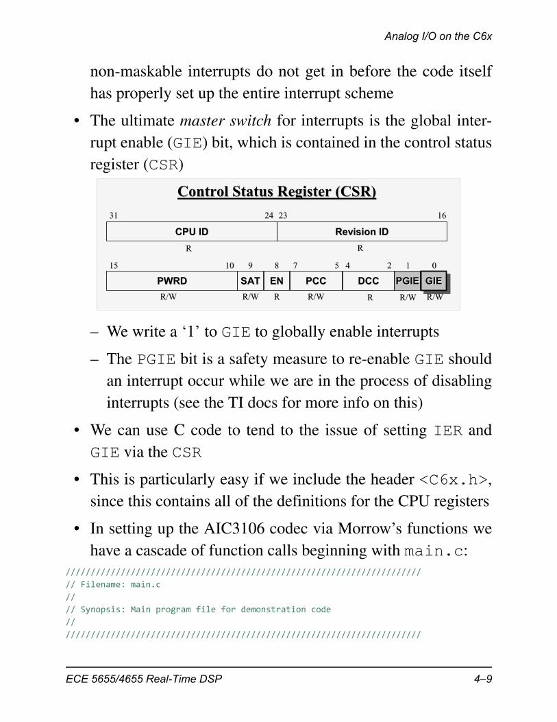
• The ultimate master switch for interrupts is the global inter-rupt enable (GIE) bit, which is contained in the control statusregister (CSR)
– We write a ‘1’ to GIE to globally enable interrupts
– The PGIE bit is a safety measure to re-enable GIE shouldan interrupt occur while we are in the process of disablinginterrupts (see the TI docs for more info on this)
• We can use C code to tend to the issue of setting IER andGIE via the CSR
• This is particularly easy if we include the header <C6x.h>,since this contains all of the definitions for the CPU registers
• In setting up the AIC3106 codec via Morrow’s functions wehave a cascade of function calls beginning with main.c:
///////////////////////////////////////////////////////////////////////
// Filename: main.c
//
// Synopsis: Main program file for demonstration code
//
///////////////////////////////////////////////////////////////////////
001122
DCCDCC
4455
PCCPCC
77
ENEN
88
SATSAT
99
PWRDPWRD
1515 1010
2323 1616
PGIEPGIE GIEGIEGIE
Revision IDRevision IDCPU IDCPU ID
3131 2424
Control Status Register (CSR)Control Status Register (CSR)
R/WR/W R/WR/W RR R/WR/W RR R/WR/W R/WR/W
RR RR
ECE 5655/4655 Real-Time DSP 4–9
Chapter 4 • Analog Input and Output
#include "DSP_Config.h"
int main()
{
// initialize DSP board
DSP_Init();
// call StartUp for application specific code
// defined in each application directory
StartUp();
// main stalls here, interrupts drive operation
while(1) {
;
} }
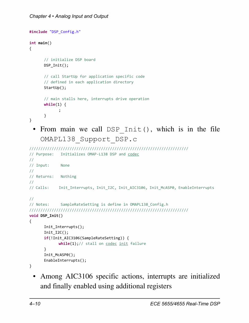
• From main we call DSP_Init(), which is in the fileOMAPL138_Support_DSP.c
///////////////////////////////////////////////////////////////////////
// Purpose: Initializes OMAP‐L138 DSP and codec
//
// Input: None
//
// Returns: Nothing
//
// Calls: Init_Interrupts, Init_I2C, Init_AIC3106, Init_McASP0, EnableInterrupts
//
// Notes: SampleRateSetting is define in OMAPL138_Config.h
///////////////////////////////////////////////////////////////////////
void DSP_Init()
{
Init_Interrupts();
Init_I2C();
if(!Init_AIC3106(SampleRateSetting)) {
while(1);// stall on codec init failure
}
Init_McASP0();
EnableInterrupts();
}
• Among AIC3106 specific actions, interrupts are initializedand finally enabled using additional registers
4–10 ECE 5655/4655 Real-Time DSP
Analog I/O on the C6x
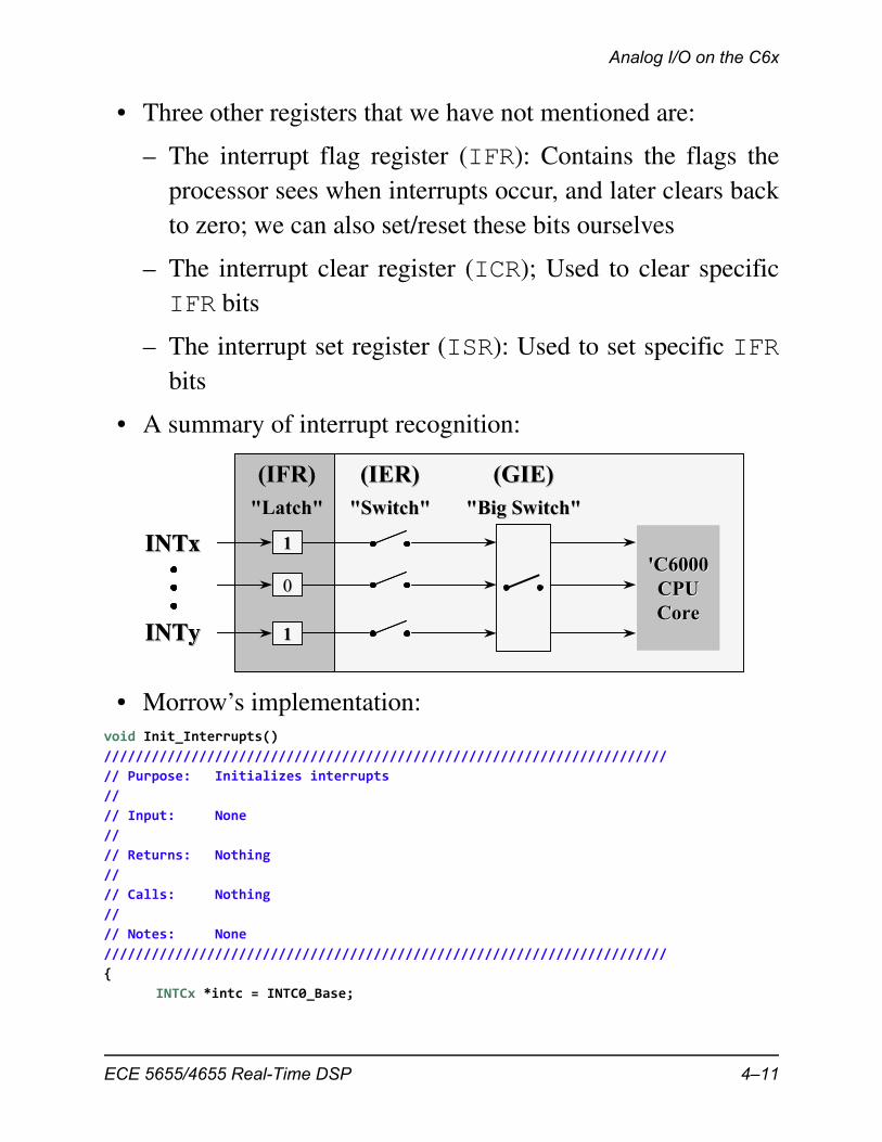
• Three other registers that we have not mentioned are:
– The interrupt flag register (IFR): Contains the flags theprocessor sees when interrupts occur, and later clears backto zero; we can also set/reset these bits ourselves
– The interrupt clear register (ICR); Used to clear specificIFR bits
– The interrupt set register (ISR): Used to set specific IFRbits
• A summary of interrupt recognition:
• Morrow’s implementation:void Init_Interrupts()
///////////////////////////////////////////////////////////////////////
// Purpose: Initializes interrupts
//
// Input: None
//
// Returns: Nothing
//
// Calls: Nothing
//
// Notes: None
///////////////////////////////////////////////////////////////////////
{
INTCx *intc = INTC0_Base;
INTxINTx 11
00
11INTyINTy
(IFR)(IFR)"Latch""Latch"
(IER)(IER)"Switch""Switch"
(GIE)(GIE)"Big Switch""Big Switch"
'C6000'C6000CPUCPUCoreCore
INTxINTx 11
00
11INTyINTy
(IFR)(IFR)"Latch""Latch"
(IER)(IER)"Switch""Switch"
(GIE)(GIE)"Big Switch""Big Switch"
'C6000'C6000CPUCPUCoreCore
ECE 5655/4655 Real-Time DSP 4–11
Chapter 4 • Analog Input and Output
// ISTP = 0x80000000; // set vector table location shared RAM
ISTP = 0x11800000; // set vector table location DSP RAM
intc‐>intmux3 = 0x0F0E0D00 | 61; // assign McASP0 irq to INT12}
void EnableInterrupts()
///////////////////////////////////////////////////////////////////////
// Purpose: Enables McASP interrupt
//
// Input: None
//
// Returns: Nothing
//
// Calls: Nothing
//
// Notes: None
///////////////////////////////////////////////////////////////////////
{
IER |= 0x1002; // enable McASP interrupt (12)
ICR = 0xffff; // clear all pending interrupts
CSR |= 1; // set GIE
}
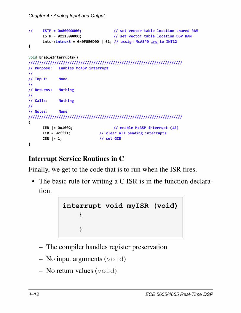
Interrupt Service Routines in C
Finally, we get to the code that is to run when the ISR fires.
• The basic rule for writing a C ISR is in the function declara-tion:
– The compiler handles register preservation
– No input arguments (void)
– No return values (void)
interrupt void myISR (void){
}
4–12 ECE 5655/4655 Real-Time DSP
Analog I/O on the C6x
• Within DSP/BIOS we have the hardware interrupt (HWI) dis-patcher (more on this when we get to DSP/BIOS), whichallows:
– Nesting of C ISRs
– Passing arguments to the ISR
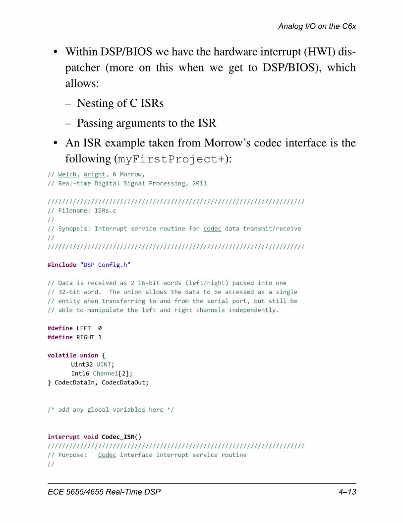
• An ISR example taken from Morrow’s codec interface is thefollowing (myFirstProject+):
// Welch, Wright, & Morrow,
// Real‐time Digital Signal Processing, 2011
///////////////////////////////////////////////////////////////////////
// Filename: ISRs.c
//
// Synopsis: Interrupt service routine for codec data transmit/receive
//
///////////////////////////////////////////////////////////////////////
#include "DSP_Config.h"
// Data is received as 2 16‐bit words (left/right) packed into one
// 32‐bit word. The union allows the data to be accessed as a single
// entity when transferring to and from the serial port, but still be
// able to manipulate the left and right channels independently.
#define LEFT 0
#define RIGHT 1
volatile union {
Uint32 UINT;
Int16 Channel[2];
} CodecDataIn, CodecDataOut;
/* add any global variables here */
interrupt void Codec_ISR()
///////////////////////////////////////////////////////////////////////
// Purpose: Codec interface interrupt service routine
//
ECE 5655/4655 Real-Time DSP 4–13
Chapter 4 • Analog Input and Output
// Input: None
//
// Returns: Nothing
//
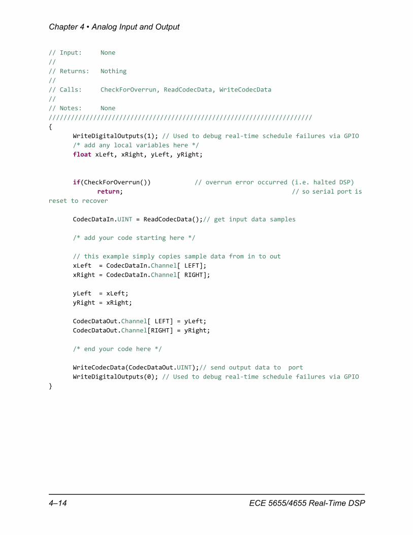
// Calls: CheckForOverrun, ReadCodecData, WriteCodecData
//
// Notes: None
///////////////////////////////////////////////////////////////////////
{
WriteDigitalOutputs(1); // Used to debug real‐time schedule failures via GPIO
/* add any local variables here */
float xLeft, xRight, yLeft, yRight;
if(CheckForOverrun()) // overrun error occurred (i.e. halted DSP)
return; // so serial port is
reset to recover
CodecDataIn.UINT = ReadCodecData();// get input data samples
/* add your code starting here */
// this example simply copies sample data from in to out
xLeft = CodecDataIn.Channel[ LEFT];
xRight = CodecDataIn.Channel[ RIGHT];
yLeft = xLeft;
yRight = xRight;
CodecDataOut.Channel[ LEFT] = yLeft;
CodecDataOut.Channel[RIGHT] = yRight;
/* end your code here */
WriteCodecData(CodecDataOut.UINT);// send output data to port
WriteDigitalOutputs(0); // Used to debug real‐time schedule failures via GPIO
}
4–14 ECE 5655/4655 Real-Time DSP
Analog I/O on the C6x
The McASP for Serial Port Audio Communication
• To actually communicate with a data producing device, suchas an A/D or D/A, requires the use of a serial port on the C6x,i.e., a McASP (C6713 uses the McBSP–Multichannel Buff-ered Serial Port)
• For details on the McASP see Chapter 23 (p. 1006) ofspruh79a, C6748 Technical Reference Manual
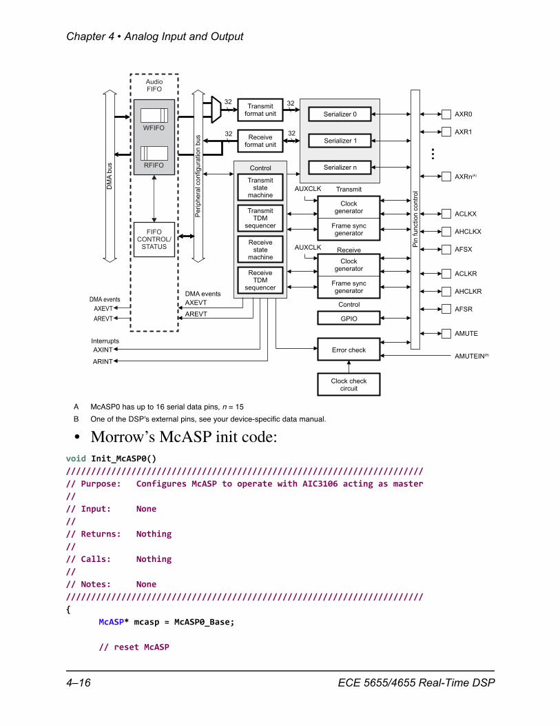
• The McASP functions as a general-purpose audio serial portoptimized for the needs of multichannel audio applications
• The McASP is useful for time-division multiplexed (TDM)stream, Inter-IC Sound (I2S) protocols, and intercomponentdigital audio interface transmission (DIT)
• The McASP consists of transmit and receive sections thatmay operate synchronized, or completely independently withseparate master clocks, bit clocks, and frame syncs, and usingdifferent transmit modes with different bit-stream formats
• The McASP module also includes up to 16 serializers thatcan be individually enabled to either transmit or receive
• In addition, all of the McASP pins can be configured as gen-eral-purpose input/output (GPIO) pins
ECE 5655/4655 Real-Time DSP 4–15
Chapter 4 • Analog Input and Output
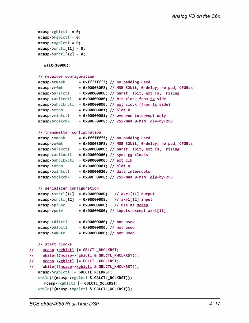
• Morrow’s McASP init code:void Init_McASP0()
///////////////////////////////////////////////////////////////////////
// Purpose: Configures McASP to operate with AIC3106 acting as master
//
// Input: None
//
// Returns: Nothing
//
// Calls: Nothing
//
// Notes: None
///////////////////////////////////////////////////////////////////////
{
McASP* mcasp = McASP0_Base;
// reset McASP
Transmitformat unit
Receiveformat unit
Transmitstate
machine
TransmitTDM
sequencer
Receivestate
machine
ReceiveTDM
sequencer
Control
32
32
32
32
Serializer 0
Serializer 1
Serializer n
AXR0
AXR1
AXRn(A)
Clockgenerator
Frame syncgenerator
AUXCLK
Clockgenerator
Frame syncgenerator
AUXCLK
Transmit
Receive
Control
GPIO
Error check
ACLKX
AHCLKX
AFSX
AFSR
AHCLKR
ACLKR
AMUTE
AMUTEIN(B)
AXEVT
AREVT
AXINT
ARINT
DMA events
Interrupts
Clock checkcircuit
AudioFIFO
WFIFO
RFIFO
FIFOCONTROL/
STATUS
AXEVT
AREVT
DMA events
DM
Abus
Periphera
lconfigura
tion
bus
Pin
function
contr
ol
A McASP0 has up to 16 serial data pins, n = 15
B One of the DSP's external pins, see your device-specific data manual.
4–16 ECE 5655/4655 Real-Time DSP
Analog I/O on the C6x
mcasp‐>gblctl = 0;
mcasp‐>rgblctl = 0;
mcasp‐>xgblctl = 0;
mcasp‐>srctl[11] = 0;
mcasp‐>srctl[12] = 0;
wait(10000);
// receiver configuration
mcasp‐>rmask = 0xffffffff; // no padding used
mcasp‐>rfmt = 0x000080F8; // MSB 32bit, 0‐delay, no pad, CFGBus
mcasp‐>afsrctl = 0x00000000; // burst, 1bit, ext fs, rising
mcasp‐>aclkrctl = 0x00000000; // bit clock from tx side
mcasp‐>ahclkrctl = 0x00000000; // ext clock (from tx side)
mcasp‐>rtdm = 0x00000001; // Slot 0
mcasp‐>rintctl = 0x00000001; // overrun interrupt only
mcasp‐>rclkchk = 0x00FF0008; // 255‐MAX 0‐MIN, div‐by‐256
// transmitter configuration
mcasp‐>xmask = 0xffffffff; // no padding used
mcasp‐>xfmt = 0x000080F8; // MSB 32bit, 0‐delay, no pad, CFGBus
mcasp‐>afsxctl = 0x00000000; // burst, 1bit, ext fs, rising
mcasp‐>aclkxctl = 0x00000000; // sync rx clocks
mcasp‐>ahclkxctl = 0x00000000; // ext clk
mcasp‐>xtdm = 0x00000001; // slot 0
mcasp‐>xintctl = 0x00000020; // data interrupts
mcasp‐>xclkchk = 0x00FF0008; // 255‐MAX 0‐MIN, div‐by‐256
// serializer configuration
mcasp‐>srctl[11] = 0x0000000D; // axr1[11] output
mcasp‐>srctl[12] = 0x0000000E; // axr1[12] input
mcasp‐>pfunc = 0x00000000; // use as mcasp
mcasp‐>pdir = 0x00000800; // inputs except axr1[11]
mcasp‐>ditctl = 0x00000000; // not used
mcasp‐>dlbctl = 0x00000000; // not used
mcasp‐>amute = 0x00000000; // not used
// start clocks
// mcasp‐>rgblctl |= GBLCTL_RHCLKRST;
// while(!(mcasp‐>rgblctl & GBLCTL_RHCLKRST));
// mcasp‐>xgblctl |= GBLCTL_XHCLKRST;
// while(!(mcasp‐>xgblctl & GBLCTL_XHCLKRST));
mcasp‐>rgblctl |= GBLCTL_RCLKRST;
while(!(mcasp‐>rgblctl & GBLCTL_RCLKRST));
mcasp‐>xgblctl |= GBLCTL_XCLKRST;
while(!(mcasp‐>xgblctl & GBLCTL_XCLKRST));
ECE 5655/4655 Real-Time DSP 4–17
Chapter 4 • Analog Input and Output
// clear any pending errors
mcasp‐>xstat = 0x0000FFFF;
mcasp‐>rstat = 0x0000FFFF;
// clear serializers
mcasp‐>rgblctl |= GBLCTL_RSRCLR;
while(!(mcasp‐>rgblctl & GBLCTL_RSRCLR));
mcasp‐>xgblctl |= GBLCTL_XSRCLR;
while(!(mcasp‐>xgblctl & GBLCTL_XSRCLR));
// state machine resets
mcasp‐>rgblctl |= GBLCTL_RSMRST;
while(!(mcasp‐>rgblctl & GBLCTL_RSMRST));
mcasp‐>xgblctl |= GBLCTL_XSMRST;
while(!(mcasp‐>xgblctl & GBLCTL_XSMRST));
// prevent output underun
mcasp‐>xbuf[11] = 0;
// start frame syncs
mcasp‐>rgblctl |= GBLCTL_RFRST;
while(!(mcasp‐>rgblctl & GBLCTL_RFRST));
mcasp‐>xgblctl |= GBLCTL_XFRST;
while(!(mcasp‐>xgblctl & GBLCTL_XFRST));}
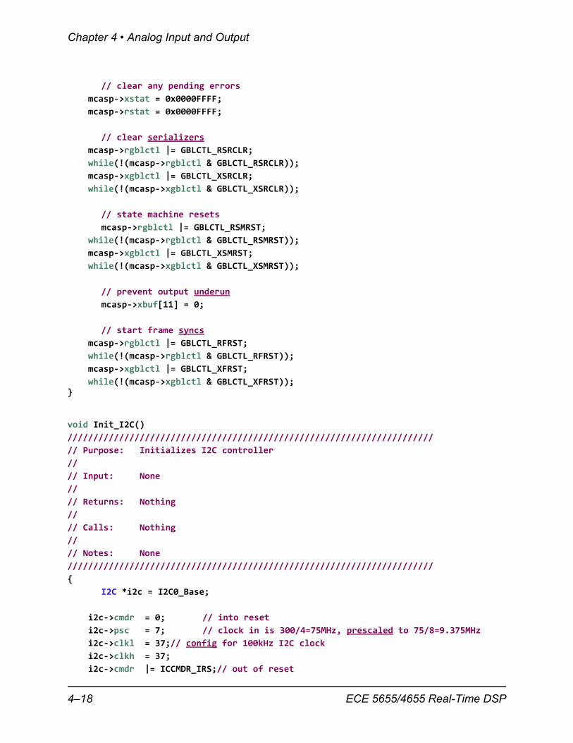
void Init_I2C()
///////////////////////////////////////////////////////////////////////
// Purpose: Initializes I2C controller
//
// Input: None
//
// Returns: Nothing
//
// Calls: Nothing
//
// Notes: None
///////////////////////////////////////////////////////////////////////
{
I2C *i2c = I2C0_Base;
i2c‐>cmdr = 0; // into reset
i2c‐>psc = 7; // clock in is 300/4=75MHz, prescaled to 75/8=9.375MHz
i2c‐>clkl = 37;// config for 100kHz I2C clock
i2c‐>clkh = 37;
i2c‐>cmdr |= ICCMDR_IRS;// out of reset
4–18 ECE 5655/4655 Real-Time DSP
Analog I/O on the C6x
}
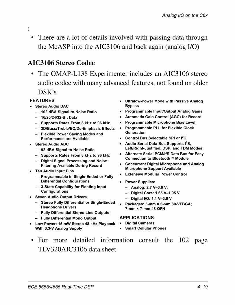
• There are a lot of details involved with passing data throughthe McASP into the AIC3106 and back again (analog I/O)
AIC3106 Stereo Codec
• The OMAP-L138 Experimenter includes an AIC3106 stereoaudio codec with many advanced features, not found on olderDSK’s
• For more detailed information consult the 102 pageTLV320AIC3106 data sheet
1FEATURES23• Stereo Audio DAC
– 102-dBA Signal-to-Noise Ratio
– 16/20/24/32-Bit Data
– Supports Rates From 8 kHz to 96 kHz
– 3D/Bass/Treble/EQ/De-Emphasis Effects
– Flexible Power Saving Modes and
Performance are Available
• Stereo Audio ADC
– 92-dBA Signal-to-Noise Ratio
– Supports Rates From 8 kHz to 96 kHz
– Digital Signal Processing and Noise
Filtering Available During Record
• Ten Audio Input Pins
– Programmable in Single-Ended or Fully
Differential Configurations
– 3-State Capability for Floating Input
Configurations
• Seven Audio Output Drivers
– Stereo Fully Differential or Single-Ended
Headphone Drivers
– Fully Differential Stereo Line Outputs
– Fully Differential Mono Output
• Low Power: 15-mW Stereo 48-kHz Playback
With 3.3-V Analog Supply
APPLICATIONS
• Power Supplies:
– Analog: 2.7 V–3.6 V.
– Digital Core: 1.65 V–1.95 V
– Digital I/O: 1.1 V–3.6 V
• Packages: 5-mm × 5-mm 80-VFBGA;
7-mm × 7-mm 48-QFN
• Digital Cameras
• Smart Cellular Phones
• Ultralow-Power Mode with Passive Analog
Bypass
• Programmable Input/Output Analog Gains
• Automatic Gain Control (AGC) for Record
• Programmable Microphone Bias Level
• Programmable PLL for Flexible Clock
Generation
• Control Bus Selectable SPI or I2C
• Audio Serial Data Bus Supports I2S,
Left/Right-Justified, DSP, and TDM Modes
• Alternate Serial PCM/I2S Data Bus for Easy
Connection to Bluetooth™ Module
• Concurrent Digital Microphone and Analog
Microphone Support Available
• Extensive Modular Power Control
ECE 5655/4655 Real-Time DSP 4–19
Chapter 4 • Analog Input and Output
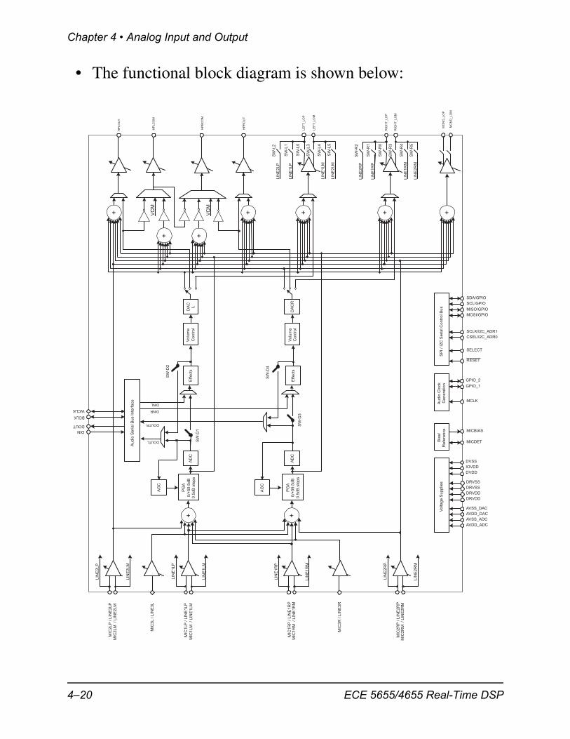
• The functional block diagram is shown below:
Au
dio
Se
ria
lB
us
Inte
rfa
ce
MIC
3L
/L
INE
3L
PG
A
0/+
59
.5d
B
0.5
dB
ste
ps
AD
C+
+
+
HP
RC
OM
HP
LC
OM
HP
LO
UT
VC
M
VC
M
DA
C
L
+
Vo
lum
e
Co
ntr
ol
Effe
cts
DIN
DOUT
BCLK
WCLK
DINL
DINR
DOUTL
DOUTR
AG
C
SW
-D2
SW
-D1
SP
I/
I2C
Se
ria
lC
on
tro
lB
us
SELECT
CSEL/I2C_ADR0
SCLK/I2C_ADR1
MOSI/GPIO
MISO/GPIO
Bia
s/
Re
fere
nce MICBIAS
SCL/GPIO
SDA/GPIO
RESET
MICDETV
olta
ge
Su
pp
lies
DVDD
DRVDD
DRVDD
DRVSS
DRVSS
DVSS
IOVDD
AVDD_ADC
AVSS_ADC
AVDD_DAC
AVSS_DAC
Au
dio
Clo
ck
Ge
ne
ratio
n
MCLK
GPIO_1
GPIO_2
+ + +
HP
RO
UT
MIC
3R
/L
INE
3R
AD
CP
GA
0/+
59
.5d
B
0.5
dB
ste
ps
+D
AC
RV
olu
me
Co
ntr
ol
Effe
cts
AG
C
SW
-D3
SW
-D4
+M
ON
O_LO
P
MO
NO
_LO
M
LIN
E1
RP
LIN
E2
RM
LIN
E2
RP
LIN
E1
RM
SW
-R0
SW
-R3
SW
-R1
SW
-R2
SW
-R4
SW
-R5
RIG
HT
_LO
P
RIG
HT
_LO
M
LIN
E1
LP
LIN
E2
LM
LIN
E2
LP
LIN
E1
LM
SW
-L0
SW
-L3
SW
-L1
SW
-L2
SW
-L4
SW
-L5
LE
FT
_LO
P
LE
FT
_LO
M
MIC
2R
M/
LIN
E2
RM
MIC
2R
P/
LIN
E2
RP
LIN
E2
RP
LIN
E2
RM
MIC
1R
M/
LIN
E1
RM
MIC
1R
P/
LIN
E1
RP
LIN
E1
RP
LIN
E1
RM
MIC
2L
M/
LIN
E2
LM
MIC
2L
P/
LIN
E2
LP
LIN
E2
LP
LIN
E2
LM
MIC
1L
M/
LIN
E1
LM
MIC
1L
P/
LIN
E1
LP
LIN
E1
LP
LIN
E1
LM
4–20 ECE 5655/4655 Real-Time DSP
Analog I/O on the C6x
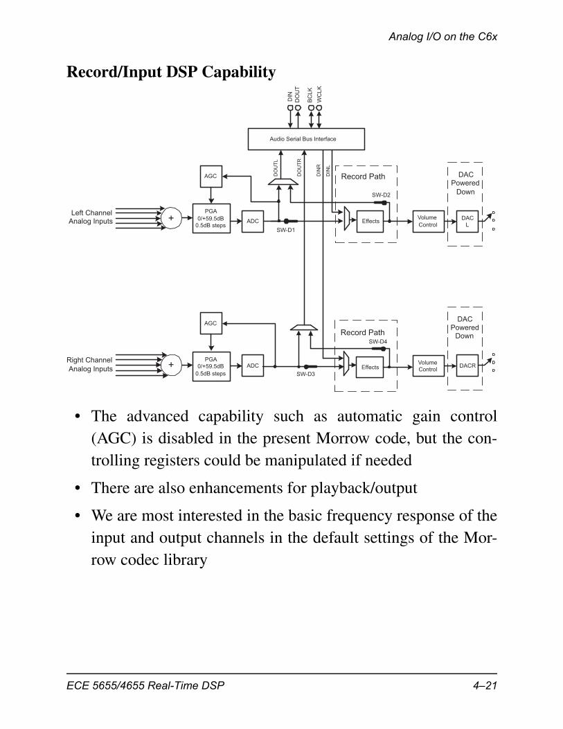
Record/Input DSP Capability
• The advanced capability such as automatic gain control(AGC) is disabled in the present Morrow code, but the con-trolling registers could be manipulated if needed
• There are also enhancements for playback/output
• We are most interested in the basic frequency response of theinput and output channels in the default settings of the Mor-row codec library
Audio Serial Bus Interface
PGA
0/+59.5dB
0.5dB stepsADC+ DAC
L
Volume
Control
DIN
DO
UT
BC
LK
WC
LK
DIN
L
DIN
R
DO
UT
L
DO
UT
R
ADCPGA
0/+59.5dB
0.5dB steps
+ DACRVolume
ControlEffects
AGC
AGC
Record Path
Record Path
DACPowered
Down
DACPowered
Down
Effects
SW-D1
SW-D2
SW-D3
SW-D4
Left ChannelAnalog Inputs
Right Channel
Analog Inputs
ECE 5655/4655 Real-Time DSP 4–21
Chapter 4 • Analog Input and Output
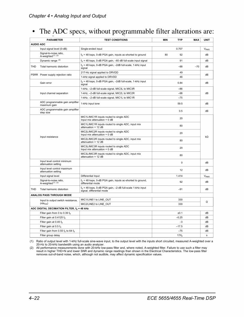
• The ADC specs, without programmable filter alterations are:_ S ( )
PARAMETER TEST CONDITIONS MIN TYP MAX UNIT
AUDIO ADC
Input signal level (0-dB) Single-ended input 0.707 VRMS
Signal-to-noise ratio,fS = 48 ksps, 0-dB PGA gain, inputs ac-shorted to ground 80 92 dB
A-weighted (1) (2)
Dynamic range (2) fS = 48 ksps, 0-dB PGA gain, –60 dB full-scale input signal 91 dB
fS = 48 ksps, 0-dB PGA gain, –2dB full-scale, 1-kHz inputTHD Total harmonic distortion –88 –70 dB
signal
217-Hz signal applied to DRVDD 49PSRR Power supply rejection ratio dB
1-kHz signal applied to DRVDD 46
fS = 48 ksps, 0-dB PGA gain, –2dB full-scale, 1-kHz inputGain error 0.84 dB
signal
1-kHz, –2-dB full-scale signal, MIC3L to MIC3R –86
Input channel separation 1-kHz, –2-dB full-scale signal, MIC2L to MIC2R –98 dB
1-kHz, –2-dB full-scale signal, MIC1L to MIC1R –75
ADC programmable gain amplifier1-kHz input tone 59.5 dB
maximum gain
ADC programmable gain amplifier0.5 dB
step size
MIC1L/MIC1R inputs routed to single ADC20
Input mix attenuation = 0 dB
MIC1L/MIC1R inputs routed to single ADC, input mix80
attenuation = 12 dB
MIC2L/MIC2R inputs routed to single ADC20
Input mix attenuation = 0 dBInput resistance k�
MIC2L/MIC2R inputs routed to single ADC, input mix80
attenuation = 12 dB
MIC3L/MIC3R inputs routed to single ADC20
Input mix attenuation = 0 dB
MIC3L/MIC3R inputs routed to single ADC, input mix80
attenuation = 12 dB
Input level control minimum0 dB
attenuation setting
Input level control maximum12 dB
attenuation setting
Input signal level Differential Input 1.414 VRMS
Signal-to-noise ratio, fS = 48 ksps, 0-dB PGA gain, inputs ac-shorted to ground,92 dB
A-weighted (1) (2) differential mode
fS = 48 ksps, 0-dB PGA gain, –2-dB full-scale 1-kHz inputTHD Total harmonic distortion –91 dB
signal, differential mode
ANALOG PASS THROUGH MODE
MIC1/LINE1 to LINE_OUT 330Input to output switch resistance, �(rdsON) MIC2/LINE2 to LINE_OUT 330
ADC DIGITAL DECIMATION FILTER, fS = 48 kHz
Filter gain from 0 to 0.39 fS ±0.1 dB
Filter gain at 0.4125 fS –0.25 dB
Filter gain at 0.45 fS –3 dB
Filter gain at 0.5 fS –17.5 dB
Filter gain from 0.55 fS to 64 fS –75 dB
Filter group delay 17/fS s
(1) Ratio of output level with 1-kHz full-scale sine-wave input, to the output level with the inputs short circuited, measured A-weighted over a20-Hz to 20-kHz bandwidth using an audio analyzer.
(2) All performance measurements done with 20-kHz low-pass filter and, where noted, A-weighted filter. Failure to use such a filter mayresult in higher THD+N and lower SNR and dynamic range readings than shown in the Electrical Characteristics. The low-pass filterremoves out-of-band noise, which, although not audible, may affect dynamic specification values.
4–22 ECE 5655/4655 Real-Time DSP
Analog I/O on the C6x
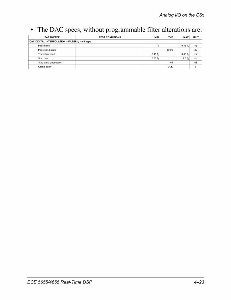
• The DAC specs, without programmable filter alterations are:PARAMETER TEST CONDITIONS MIN TYP MAX UNIT
DAC DIGITAL INTERPOLATION – FILTER fS = 48 ksps
Pass band 0 0.45 fS Hz
Pass-band ripple ±0.06 dB
Transition band 0.45 fS 0.55 fS Hz
Stop band 0.55 fS 7.5 fS Hz
Stop-band attenuation 65 dB
Group delay 21/fS s
ECE 5655/4655 Real-Time DSP 4–23
Chapter 4 • Analog Input and Output
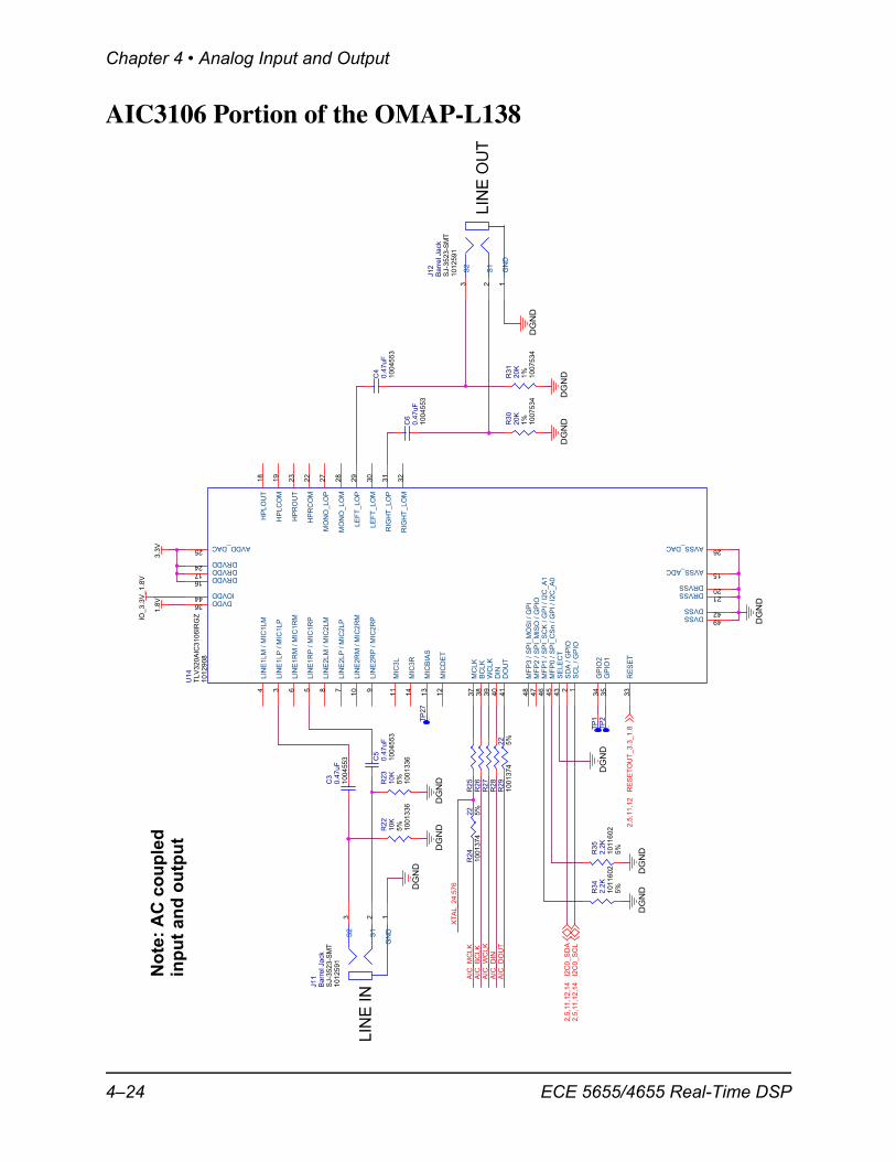
AIC3106 Portion of the OMAP-L138
LIN
E IN
LIN
E O
UT
AIC
_W
CL
K
AIC
_M
CL
K
XT
AL_24.5
76
AIC
_D
OU
T
XT
AL_24.5
76
AIC
_D
IN
AIC
_B
CL
K
I2C
0_
SC
L2
,5,1
1,1
2,1
4
RE
SE
TO
UT
_3
.3_
1.8
2,5
,11
,12
I2C
0_
SD
A2
,5,1
1,1
2,1
4
DG
ND
DG
ND
IO_
3.3
V_
1.8
V
DG
ND
DG
ND
DG
ND
1.8
V
DG
ND
DG
ND
3.3
V
DG
ND
DG
ND
3.3
V
DG
ND
DG
ND
R3
5
10
11
602
2.2
K
5%
R2
3
10
01
336
10
K5
%
C7
10
0.1
R3
4
10
11
602
2.2
K
5%
R3
0
10
07
534
20
K1
%
J1
1
10
12
591
SJ-3
52
3-S
MT
Ba
rre
l Ja
ck
123
GN
D
S1
S2
C6
10
04
553
0.4
7u
F
C4
10
04
553
0.4
7u
F
R2
7
TP
2.
R2
8
R2
6
TP
27
.
U1
4
10
12
908
TL
V3
20
AIC
31
06
IRG
Z
35
36
37
38
39
40
41
42
43
44
45
46
47
48 1234 56 78 9
10
11
12
13
14
151617
18
19
2021
22
23
24
25 26
27
28
29
30
31
32
33
34
49
GP
IO1
DVDD
MC
LK
BC
LK
WC
LK
DIN
DO
UT
DVSS
SE
LE
CT
IOVDD
MF
P0
/ S
PI_
CS
n /
GP
I /
I2C
_A
0M
FP
1 /
SP
I_S
CK
/ G
PI
/ I2
C_
A1
MF
P2
/ S
PI_
MIS
O /
GP
IOM
FP
3 /
SP
I_M
OS
I /
GP
I
SC
L /
GP
IOS
DA
/ G
PIO
LIN
E1
LP
/ M
IC1
LP
LIN
E1
LM
/ M
IC1
LM
LIN
E1
RP
/ M
IC1
RP
LIN
E1R
M /
MIC
1R
M
LIN
E2
LP
/ M
IC2
LP
LIN
E2
LM
/ M
IC2
LM
LIN
E2
RP
/ M
IC2
RP
LIN
E2
RM
/ M
IC2
RM
MIC
3L
MIC
DE
T
MIC
BIA
S
MIC
3R
AVSS_ADCDRVDDDRVDD
HP
LO
UT
HP
LC
OM
DRVSSDRVSS
HP
RC
OM
HP
RO
UT
DRVDD
AVDD_DAC AVSS_DAC
MO
NO
_L
OP
MO
NO
_L
OM
LE
FT
_L
OP
LE
FT
_L
OM
RIG
HT
_L
OP
RIG
HT
_L
OM
RE
SE
T
GP
IO2
DVSS
TP
1.
C3
10
04
553
0.4
7u
F
R2
91
00
13
74
22
5%
C5
10
04
553
0.4
7u
F
R3
1
10
07
534
20
K1
%
R2
41
00
1374
22
5%
R2
2
10
01
336
10
K5
%
J1
2
10
12
591
SJ-3
523-S
MT
Ba
rre
l Ja
ck
123
GN
D
S1
S2
R2
5
No
te:
AC
co
up
led
inp
ut
and
ou
tpu
t
4–24 ECE 5655/4655 Real-Time DSP
Analog I/O on the C6x
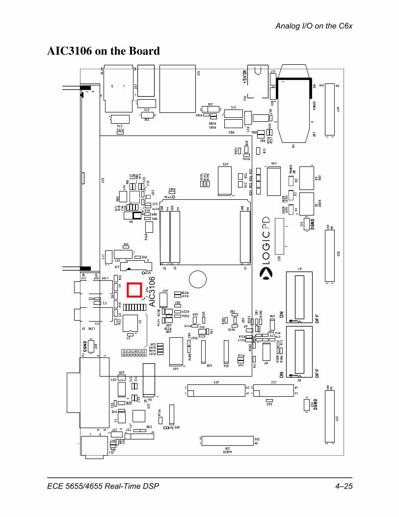
AIC3106 on the Board
AIC
3106
ECE 5655/4655 Real-Time DSP 4–25
Chapter 4 • Analog Input and Output
A Simple Interrupt Loop Program
• The myFirstProject_Plus is an example of a simpleinterrupt driven program for sample-by-sample processing ofanalog/audio I/O
• Will mostly consider this as a black box program, howeverbased on the preceding discussion, some additional knowl-edge has been obtain about the operating principles
• The code listings are given below, with descriptions follow-ing:
// Welch, Wright, & Morrow,
// Real‐time Digital Signal Processing, 2011
// Modified by Mark Wickert February 2012
///////////////////////////////////////////////////////////////////////
// Filename: ISRs_Plus.c
//
// Synopsis: Interrupt service routine for codec data transmit/receive
//
///////////////////////////////////////////////////////////////////////
#include "DSP_Config.h"
// Function Prototypes
long int rand_int(void);
// Data is received as 2 16‐bit words (left/right) packed into one
// 32‐bit word. The union allows the data to be accessed as a single
// entity when transferring to and from the serial port, but still be
// able to manipulate the left and right channels independently.
#define LEFT 0
#define RIGHT 1
volatile union {
Uint32 UINT;
Int16 Channel[2];
} CodecDataIn, CodecDataOut;
4–26 ECE 5655/4655 Real-Time DSP
Analog I/O on the C6x
/* add any global variables here */
interrupt void Codec_ISR()
///////////////////////////////////////////////////////////////////////
// Purpose: Codec interface interrupt service routine
//
// Input: None
//
// Returns: Nothing
//
// Calls: CheckForOverrun, ReadCodecData, WriteCodecData
//
// Notes: None
///////////////////////////////////////////////////////////////////////
{
/* add any local variables here */
WriteDigitalOutputs(1); // Write to GPIO J15, pin 6; begin ISR timing pulse
float xLeft, xRight, yLeft, yRight;
short k;
if(CheckForOverrun()) // overrun error occurred (i.e. halted DSP)
return; // so serial port is
reset to recover
CodecDataIn.UINT = ReadCodecData();// get input data samples
/* add your code starting here */
// this example simply copies sample data from in to out
xLeft = CodecDataIn.Channel[ LEFT];
xRight = CodecDataIn.Channel[ RIGHT];
//*********** Input Noise Testing ****************
//Generate left and right noise samples
xLeft = ((short)rand_int())>>2;
xRight = ((short)rand_int())>>2;
//************************************************
yLeft = xLeft;
yRight = xRight;
CodecDataOut.Channel[ LEFT] = yLeft;
CodecDataOut.Channel[RIGHT] = yRight;
for(k=0; k<1; k++)
{
// Idle loop to load processor inside ISR
ECE 5655/4655 Real-Time DSP 4–27
Chapter 4 • Analog Input and Output
}
/* end your code here */
WriteCodecData(CodecDataOut.UINT);// send output data to port
WriteDigitalOutputs(0); // Write to GPIO J15, pin 6; end ISR timing pulse
}
//White noise generator for filter noise testing
long int rand_int(void)
{
static long int a = 100001;
a = (a*125) % 2796203;
return a;}
More Details
• The sampling rate is set by uncommenting/commenting#defines from DSP_Config.h
// Welch, Wright, & Morrow,
// Real‐time Digital Signal Processing, 2011
///////////////////////////////////////////////////////////////////////
// Filename: DSP_Config.h
//
// Synopsis: Declarations for configuring the codec parameters
//
///////////////////////////////////////////////////////////////////////
#ifndefDSP_CONFIG_H_INCLUDED
#define DSP_CONFIG_H_INCLUDED
#include "OMAPL138_Support_DSP.h"
// uncomment just the line for the sample rate when using the OMAP‐L138
#define SampleRateSetting AIC3106Fs48kHz// 48kHz sample rate
//#define SampleRateSetting AIC3106Fs96kHz// 96kHz sample rate
//#define SampleRateSetting AIC3106Fs32kHz// 32kHz sample rate
//#define SampleRateSetting AIC3106Fs24kHz// 24kHz sample rate
//#define SampleRateSetting AIC3106Fs16kHz// 16kHz sample rate
//#define SampleRateSetting AIC3106Fs12kHz// 12kHz sample rate
//#define SampleRateSetting AIC3106Fs8kHz// 8kHz sample rate
#endif
4–28 ECE 5655/4655 Real-Time DSP
Testing the AIC3106 in the Lab
• Make sure the function StartUp() conatins GPIO initializa-tion, i.e.,
void StartUp(){
InitDigitalOutputs();}
Testing the AIC3106 in the Lab
• A combination of lab hardware and software can be used totake measurements on the performance of the OMAP-L138
– With the AIC3106 configured to loop signals through wecan characterize the ADC/DAC path
– If we internally generate a white noise sequence, we cancharacterize just the DAC output path
• In Assignment #3 these options are explored in detail
Noise Capture to Characterize DAC
• A simple measurement of the DAC path can be obtained bygenerating white noise in software and sending directly to theoutput, i.e., from ISRs_Plus.c we can set-up the sourcewith a scale factor of 4
...//*********** Input Noise Testing ****************//Generate left and right noise samples
xLeft = ((short)rand_int())>>2;xRight = ((short)rand_int())>>2;
//************************************************...
ECE 5655/4655 Real-Time DSP 4–29
Chapter 4 • Analog Input and Output
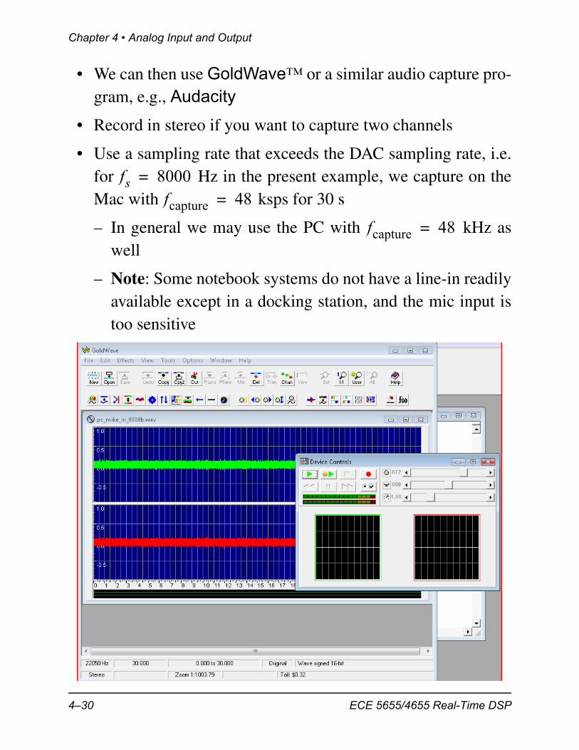
• We can then use GoldWave™ or a similar audio capture pro-gram, e.g., Audacity
• Record in stereo if you want to capture two channels
• Use a sampling rate that exceeds the DAC sampling rate, i.e.for Hz in the present example, we capture on theMac with ksps for 30 s
– In general we may use the PC with kHz aswell
– Note: Some notebook systems do not have a line-in readilyavailable except in a docking station, and the mic input istoo sensitive
fs 8000=fcapture 48=
fcapture 48=
4–30 ECE 5655/4655 Real-Time DSP
Testing the AIC3106 in the Lab
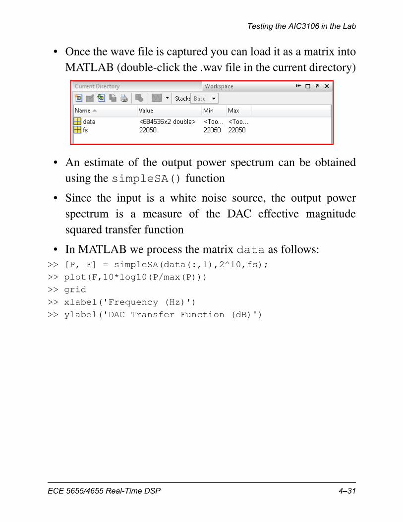
• Once the wave file is captured you can load it as a matrix intoMATLAB (double-click the .wav file in the current directory)
• An estimate of the output power spectrum can be obtainedusing the simpleSA() function
• Since the input is a white noise source, the output powerspectrum is a measure of the DAC effective magnitudesquared transfer function
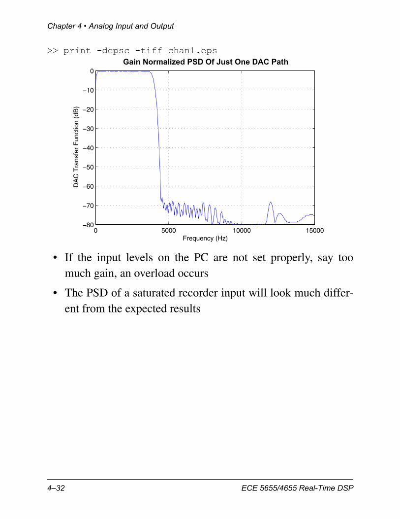
• In MATLAB we process the matrix data as follows:>> [P, F] = simpleSA(data(:,1),2^10,fs);>> plot(F,10*log10(P/max(P)))>> grid>> xlabel('Frequency (Hz)')>> ylabel('DAC Transfer Function (dB)')
ECE 5655/4655 Real-Time DSP 4–31
Chapter 4 • Analog Input and Output
>> print -depsc -tiff chan1.eps
• If the input levels on the PC are not set properly, say toomuch gain, an overload occurs
• The PSD of a saturated recorder input will look much differ-ent from the expected results
0 5000 10000 15000−80
−70
−60
−50
−40
−30
−20
−10
0
Frequency (Hz)
DA
C T
rans
fer
Fun
ctio
n (d
B)
Gain Normalized PSD Of Just One DAC Path
4–32 ECE 5655/4655 Real-Time DSP
Testing the AIC3106 in the Lab
ISR Timing Using GPIO
• Moving forward the use of the AIC3106 and the inclusion ofreal-time DSP algorithms will a mainstay
• The source file ISRs_Plus.c includes code to write to theGPIO J15, pin 6/* add any local variables here */
WriteDigitalOutputs(1); // Write to GPIO J15, pin 6; begin ISR timing pulse
// ISR code to read and right to CODEC and DSP algorithms
WriteDigitalOutputs(0); // Write to GPIO J15, pin 6; end ISR timing pulse
• By writing a ‘1’ at the beginning of the ISR and ‘0’ at theend, a timing pulse can be viewed on a logic analyzer, whichdescribes the approximate processor utilization
• Embedded in the above ISR is a for loop to make it clear the afinite amount of processor resources are available for real-time processing
• The 100 cycle empty loop does use CPU cycles
ECE 5655/4655 Real-Time DSP 4–33
Chapter 4 • Analog Input and Output
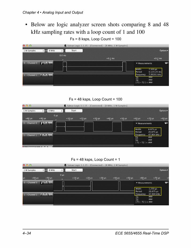
• Below are logic analyzer screen shots comparing 8 and 48kHz sampling rates with a loop count of 1 and 100
Fs = 8 ksps, Loop Count = 100
Fs = 48 ksps, Loop Count = 100
Fs = 48 ksps, Loop Count = 1
4–34 ECE 5655/4655 Real-Time DSP
VC5505 with AIC3204 Codec
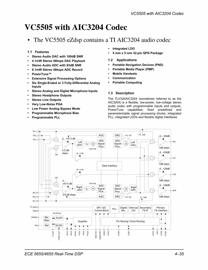
VC5505 with AIC3204 Codec
• The VC5505 eZdsp contains a TI AIC3204 audio codec
Left
ADC
DRC
tplLeft
DAC
AGC
��
�
�
�
ADC
Signal
Proc.
DAC
Signal
Proc.
Right
ADC
DRC
tprRightDAC
AGC
ADC
SignalProc.
DAC
Signal
Proc.�
�
�
�
CM
CM
Vol. Ctrl
Vol. Ctrl
Gain Adj.
Gain Adj.
0…
+47.5 dB
0.5 dB steps
0…+47.5 dB
0.5 dB
steps
-6...+29dB
1dB steps
-6...+29dB
1dB steps
-6...+29dB
1dB steps
-6...+29dB
1dB steps
SPI / I2C
Control Block
Pin Muxing / Clock Routing
Secondary
I2S IF
Primary
I2S Interface
Digital
Mic.
Interrupt
Ctrl
ALDO
DLDO
PLL
Mic
Bias
Ref
PI_Select
MicBias
Ref
LD
OS
ele
ct
Supplies
LD
Oin
HPVdd
DV
dd
AV
dd
IOV
dd
AV
ss
DV
ss
IOV
ss
SC
L/S
SZ
SD
A/M
OS
I
MIS
O
SC
LK
MC
LK
GP
IO
DO
UT
DIN
BC
LK
WC
LK
HPL
LOL
HPR
LOR
IN1_R
IN2_R
IN3_R
IN3_L
IN2_L
IN1_L
Reset
-30...0 dB
-30...0 dB
Data Interface
-72...0dB
-72...0dB
�
��
1.1 Features
1.2 Applications
1.3 Description
• Integrated LDO
• 5 mm x 5 mm 32-pin QFN Package• Stereo Audio DAC with 100dB SNR
• 4.1mW Stereo 48ksps DAC Playback
• Portable Navigation Devices (PND)• Stereo Audio ADC with 93dB SNR
• Portable Media Player (PMP)• 6.1mW Stereo 48ksps ADC Record
• Mobile Handsets• PowerTune™
• Communication• Extensive Signal Processing Options
• Portable Computing• Six Single-Ended or 3 Fully-Differential Analog
Inputs
• Stereo Analog and Digital Microphone Inputs
• Stereo Headphone OutputsThe TLV320AIC3204 (sometimes referred to as the• Stereo Line OutputsAIC3204) is a flexible, low-power, low-voltage stereo
• Very Low-Noise PGAaudio codec with programmable inputs and outputs,
• Low Power Analog Bypass Mode PowerTune capabilities, fixed predefined and• Programmable Microphone Bias parameterizable signal processing blocks, integrated
PLL, integrated LDOs and flexible digital interfaces.• Programmable PLL
ECE 5655/4655 Real-Time DSP 4–35
Chapter 4 • Analog Input and Output
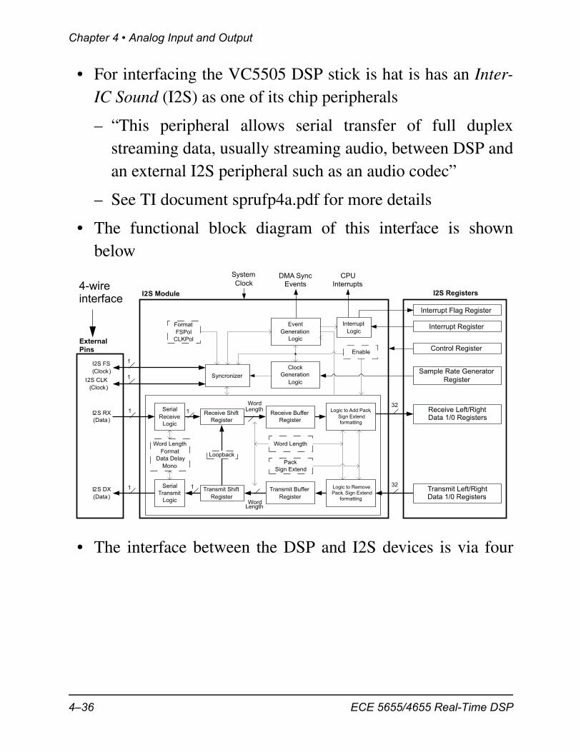
• For interfacing the VC5505 DSP stick is hat is has an Inter-IC Sound (I2S) as one of its chip peripherals
– “This peripheral allows serial transfer of full duplexstreaming data, usually streaming audio, between DSP andan external I2S peripheral such as an audio codec”
– See TI document sprufp4a.pdf for more details
• The functional block diagram of this interface is shownbelow
• The interface between the DSP and I2S devices is via four
Transmit Shift
Register
I2S Module
Receive Shift
Register
Event
Generation
Logic
Syncronizer
Clock
Generation
Logic
I2S Registers
I2S RX
(Data)
I2S FS
(Clock)
I2S CLK
(Clock)
I2S DX
(Data)
External
Pins
1
1
Interrupt Flag Register
Interrupt Register
Sample Rate Generator
Register
Control Register
Pack
Sign Extend
Word Length
Format
Data Delay
Mono
Transmit Left/RightData 1/0 Registers
DMA Sync
Events
32
32
Format
FSPol
CLKPol
Receive Buffer
Register
Loopback
Enable
Logic to Add Pack,
Sign Extendformatting
Logic to RemovePack, Sign Extend
formatting
Word Length
Serial
Receive
Logic
Serial
Transmit
Logic
WordLength
WordLength
1
1
1
1
Interrupt
Logic
CPU
Interrupts
System
Clock
Transmit Buffer
Register
Receive Left/RightData 1/0 Registers
4-wireinterface
4–36 ECE 5655/4655 Real-Time DSP
VC5505 with AIC3204 Codec
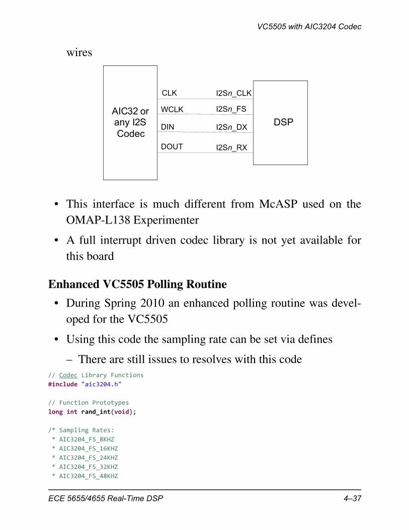
wires
• This interface is much different from McASP used on theOMAP-L138 Experimenter
• A full interrupt driven codec library is not yet available forthis board
Enhanced VC5505 Polling Routine
• During Spring 2010 an enhanced polling routine was devel-oped for the VC5505
• Using this code the sampling rate can be set via defines
– There are still issues to resolves with this code// Codec Library Functions
#include "aic3204.h"
// Function Prototypes
long int rand_int(void);
/* Sampling Rates:
* AIC3204_FS_8KHZ
* AIC3204_FS_16KHZ
* AIC3204_FS_24KHZ
* AIC3204_FS_32KHZ
* AIC3204_FS_48KHZ
DSPAIC32 orany I2S
Codec
I2S _CLKn
I2S _FSn
I2S _DXn
I2S _RXn
CLK
WCLK
DIN
DOUT
ECE 5655/4655 Real-Time DSP 4–37
Chapter 4 • Analog Input and Output
* AIC3204_FS_96KHZ
*/
short fs = AIC3204_FS_24KHZ;
void main(void)
{
//Define working variables
short i = 0;
short l_chan, r_chan;
short buffer[128];
// Initialize Polling
comm_poll();
while(1)
{
// Get sample using inputs
//input_sample(&l_chan, &r_chan);
// Get random sample
r_chan = ((short) rand_int())>>3;
/* Fill buffer */
buffer[i] = r_chan;
i += 1;
if (i == 128) i = 0;
/* Write Digital audio input */
output_sample(l_chan, r_chan);
}
}
//White noise generator for filter noise testing
long int rand_int(void)
{
static long int a = 100001;
a = (a*125) % 2796203;
return a;}
// aic3204.c
/*
* ECE5655
* Sean O'Brien
*/
4–38 ECE 5655/4655 Real-Time DSP
VC5505 with AIC3204 Codec
#include "aic3204.h"
#include "usbstk5505.h"
#include "usbstk5505_gpio.h"
#include "usbstk5505_i2c.h"
// Polling Masks
#define AIC3204_I2C_ADDR 0x18
#define XmitL 0x10
#define XmitR 0x20
#define RcvR 0x08
#define RcvL 0x04
// Function Prototypes
static Int16 AIC3204_rget(Uint16 regnum, Uint16* regval);
static Int16 AIC3204_rset(Uint16 regnum, Uint16 regval);
// Sampling rate variable
extern short fs;
/* ‐‐‐‐‐‐‐‐‐‐‐‐‐‐‐‐‐‐‐‐‐‐‐‐‐‐‐‐‐‐‐‐‐‐‐‐‐‐‐‐‐‐‐‐‐‐‐‐‐‐‐‐‐‐‐‐‐‐‐‐‐‐‐‐‐‐‐‐‐‐‐‐ *
* *
* _AIC3204_rget(regnum, regval) *
* *
* Return value of codec register regnum *
* *
* ‐‐‐‐‐‐‐‐‐‐‐‐‐‐‐‐‐‐‐‐‐‐‐‐‐‐‐‐‐‐‐‐‐‐‐‐‐‐‐‐‐‐‐‐‐‐‐‐‐‐‐‐‐‐‐‐‐‐‐‐‐‐‐‐‐‐‐‐‐‐‐‐ */
static Int16 AIC3204_rget(Uint16 regnum, Uint16* regval)
{
Int16 retcode = 0;
Uint8 cmd[2];
cmd[0] = regnum & 0x007F; // 7‐bit Device Address
cmd[1] = 0;
retcode |= USBSTK5505_I2C_write(AIC3204_I2C_ADDR, cmd, 1);
retcode |= USBSTK5505_I2C_read(AIC3204_I2C_ADDR, cmd, 1);
*regval = cmd[0];
USBSTK5505_wait(10);
return retcode;
}
/* ‐‐‐‐‐‐‐‐‐‐‐‐‐‐‐‐‐‐‐‐‐‐‐‐‐‐‐‐‐‐‐‐‐‐‐‐‐‐‐‐‐‐‐‐‐‐‐‐‐‐‐‐‐‐‐‐‐‐‐‐‐‐‐‐‐‐‐‐‐‐‐‐ *
* *
* _AIC3204_rset(regnum, regval) *
* *
ECE 5655/4655 Real-Time DSP 4–39
Chapter 4 • Analog Input and Output
* Set codec register regnum to value regval *
* *
* ‐‐‐‐‐‐‐‐‐‐‐‐‐‐‐‐‐‐‐‐‐‐‐‐‐‐‐‐‐‐‐‐‐‐‐‐‐‐‐‐‐‐‐‐‐‐‐‐‐‐‐‐‐‐‐‐‐‐‐‐‐‐‐‐‐‐‐‐‐‐‐‐ */
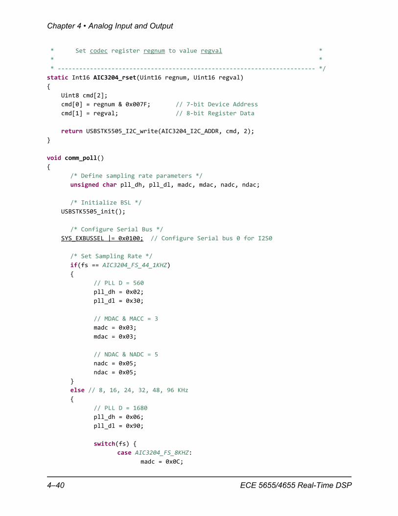
static Int16 AIC3204_rset(Uint16 regnum, Uint16 regval)
{
Uint8 cmd[2];
cmd[0] = regnum & 0x007F; // 7‐bit Device Address
cmd[1] = regval; // 8‐bit Register Data
return USBSTK5505_I2C_write(AIC3204_I2C_ADDR, cmd, 2);
}
void comm_poll()
{
/* Define sampling rate parameters */
unsigned char pll_dh, pll_dl, madc, mdac, nadc, ndac;
/* Initialize BSL */
USBSTK5505_init();
/* Configure Serial Bus */
SYS_EXBUSSEL |= 0x0100; // Configure Serial bus 0 for I2S0
/* Set Sampling Rate */
if(fs == AIC3204_FS_44_1KHZ)
{
// PLL D = 560
pll_dh = 0x02;
pll_dl = 0x30;
// MDAC & MACC = 3
madc = 0x03;
mdac = 0x03;
// NDAC & NADC = 5
nadc = 0x05;
ndac = 0x05;
}
else // 8, 16, 24, 32, 48, 96 KHz
{
// PLL D = 1680
pll_dh = 0x06;
pll_dl = 0x90;
switch(fs) {
case AIC3204_FS_8KHZ:
madc = 0x0C;
4–40 ECE 5655/4655 Real-Time DSP
VC5505 with AIC3204 Codec
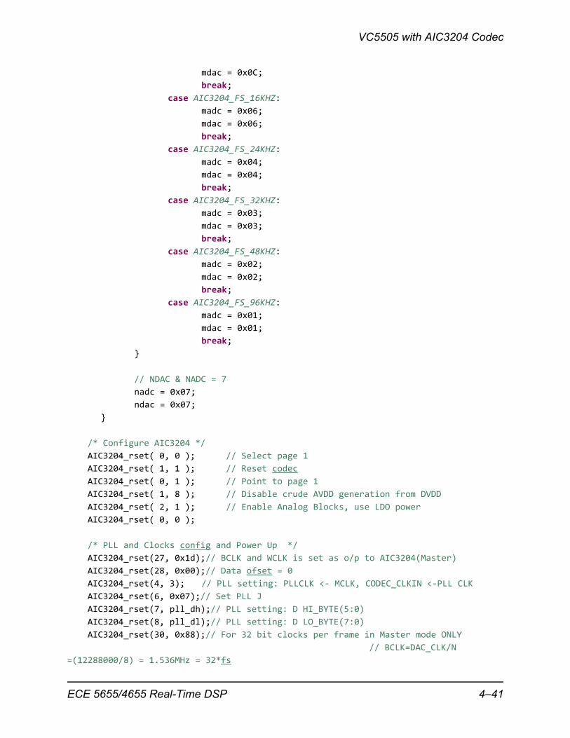
mdac = 0x0C;
break;
case AIC3204_FS_16KHZ:
madc = 0x06;
mdac = 0x06;
break;
case AIC3204_FS_24KHZ:
madc = 0x04;
mdac = 0x04;
break;
case AIC3204_FS_32KHZ:
madc = 0x03;
mdac = 0x03;
break;
case AIC3204_FS_48KHZ:
madc = 0x02;
mdac = 0x02;
break;
case AIC3204_FS_96KHZ:
madc = 0x01;
mdac = 0x01;
break;
}
// NDAC & NADC = 7
nadc = 0x07;
ndac = 0x07;
}
/* Configure AIC3204 */
AIC3204_rset( 0, 0 ); // Select page 1
AIC3204_rset( 1, 1 ); // Reset codec
AIC3204_rset( 0, 1 ); // Point to page 1
AIC3204_rset( 1, 8 ); // Disable crude AVDD generation from DVDD
AIC3204_rset( 2, 1 ); // Enable Analog Blocks, use LDO power
AIC3204_rset( 0, 0 );
/* PLL and Clocks config and Power Up */
AIC3204_rset(27, 0x1d);// BCLK and WCLK is set as o/p to AIC3204(Master)
AIC3204_rset(28, 0x00);// Data ofset = 0
AIC3204_rset(4, 3); // PLL setting: PLLCLK <‐ MCLK, CODEC_CLKIN <‐PLL CLK
AIC3204_rset(6, 0x07);// Set PLL J
AIC3204_rset(7, pll_dh);// PLL setting: D HI_BYTE(5:0)
AIC3204_rset(8, pll_dl);// PLL setting: D LO_BYTE(7:0)
AIC3204_rset(30, 0x88);// For 32 bit clocks per frame in Master mode ONLY
// BCLK=DAC_CLK/N
=(12288000/8) = 1.536MHz = 32*fs
ECE 5655/4655 Real-Time DSP 4–41
Chapter 4 • Analog Input and Output
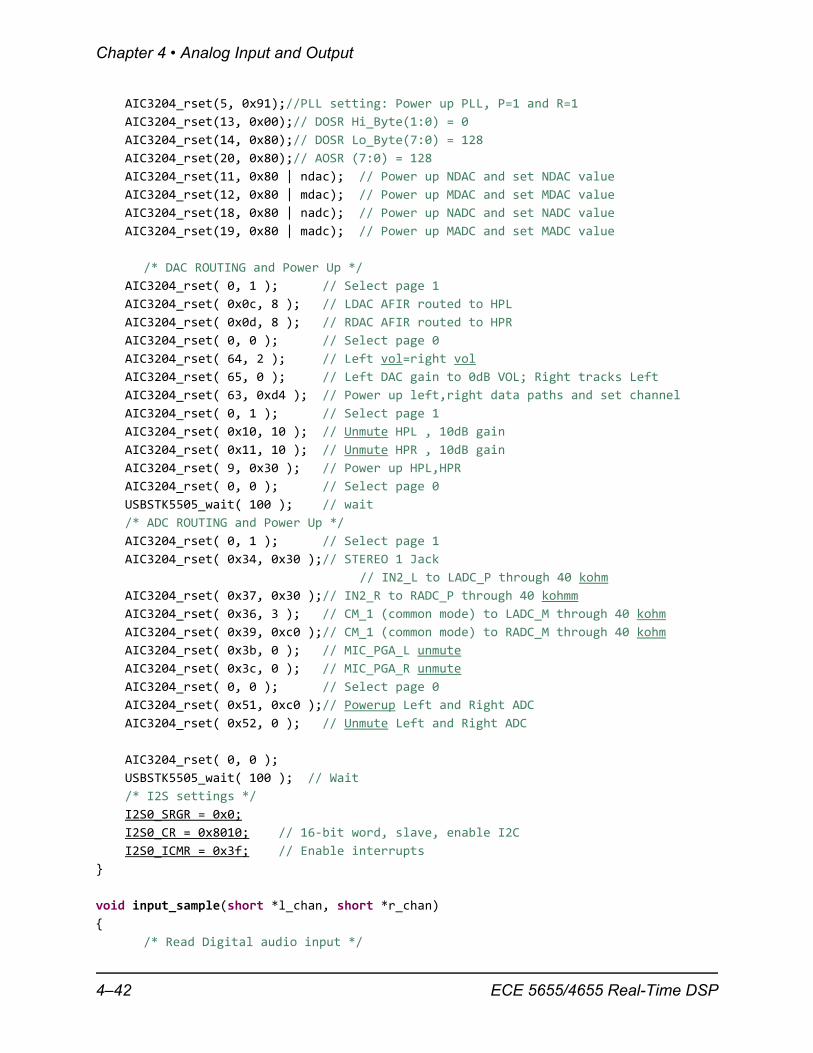
AIC3204_rset(5, 0x91);//PLL setting: Power up PLL, P=1 and R=1
AIC3204_rset(13, 0x00);// DOSR Hi_Byte(1:0) = 0
AIC3204_rset(14, 0x80);// DOSR Lo_Byte(7:0) = 128
AIC3204_rset(20, 0x80);// AOSR (7:0) = 128
AIC3204_rset(11, 0x80 | ndac); // Power up NDAC and set NDAC value
AIC3204_rset(12, 0x80 | mdac); // Power up MDAC and set MDAC value
AIC3204_rset(18, 0x80 | nadc); // Power up NADC and set NADC value
AIC3204_rset(19, 0x80 | madc); // Power up MADC and set MADC value
/* DAC ROUTING and Power Up */
AIC3204_rset( 0, 1 ); // Select page 1
AIC3204_rset( 0x0c, 8 ); // LDAC AFIR routed to HPL
AIC3204_rset( 0x0d, 8 ); // RDAC AFIR routed to HPR
AIC3204_rset( 0, 0 ); // Select page 0
AIC3204_rset( 64, 2 ); // Left vol=right vol
AIC3204_rset( 65, 0 ); // Left DAC gain to 0dB VOL; Right tracks Left
AIC3204_rset( 63, 0xd4 ); // Power up left,right data paths and set channel
AIC3204_rset( 0, 1 ); // Select page 1
AIC3204_rset( 0x10, 10 ); // Unmute HPL , 10dB gain
AIC3204_rset( 0x11, 10 ); // Unmute HPR , 10dB gain
AIC3204_rset( 9, 0x30 ); // Power up HPL,HPR
AIC3204_rset( 0, 0 ); // Select page 0
USBSTK5505_wait( 100 ); // wait
/* ADC ROUTING and Power Up */
AIC3204_rset( 0, 1 ); // Select page 1
AIC3204_rset( 0x34, 0x30 );// STEREO 1 Jack
// IN2_L to LADC_P through 40 kohm
AIC3204_rset( 0x37, 0x30 );// IN2_R to RADC_P through 40 kohmm
AIC3204_rset( 0x36, 3 ); // CM_1 (common mode) to LADC_M through 40 kohm
AIC3204_rset( 0x39, 0xc0 );// CM_1 (common mode) to RADC_M through 40 kohm
AIC3204_rset( 0x3b, 0 ); // MIC_PGA_L unmute
AIC3204_rset( 0x3c, 0 ); // MIC_PGA_R unmute
AIC3204_rset( 0, 0 ); // Select page 0
AIC3204_rset( 0x51, 0xc0 );// Powerup Left and Right ADC
AIC3204_rset( 0x52, 0 ); // Unmute Left and Right ADC
AIC3204_rset( 0, 0 );
USBSTK5505_wait( 100 ); // Wait
/* I2S settings */
I2S0_SRGR = 0x0;
I2S0_CR = 0x8010; // 16‐bit word, slave, enable I2C
I2S0_ICMR = 0x3f; // Enable interrupts
}
void input_sample(short *l_chan, short *r_chan)
{
/* Read Digital audio input */
4–42 ECE 5655/4655 Real-Time DSP
VC5505 with AIC3204 Codec
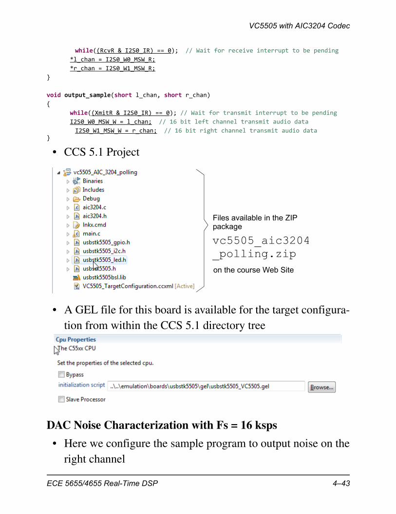
while((RcvR & I2S0_IR) == 0); // Wait for receive interrupt to be pending
*l_chan = I2S0_W0_MSW_R;
*r_chan = I2S0_W1_MSW_R;
}
void output_sample(short l_chan, short r_chan)
{
while((XmitR & I2S0_IR) == 0); // Wait for transmit interrupt to be pending
I2S0_W0_MSW_W = l_chan; // 16 bit left channel transmit audio data
I2S0_W1_MSW_W = r_chan; // 16 bit right channel transmit audio data}
• CCS 5.1 Project
• A GEL file for this board is available for the target configura-tion from within the CCS 5.1 directory tree
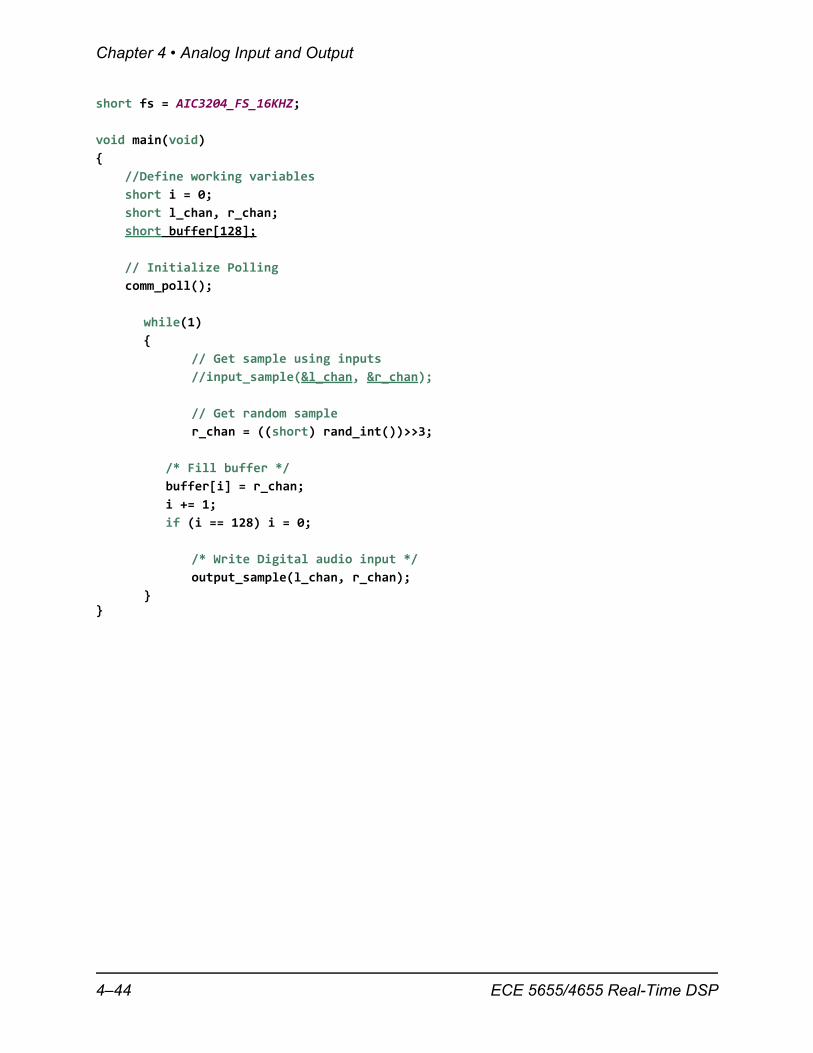
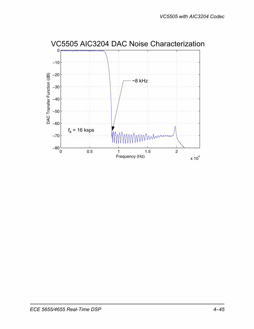
DAC Noise Characterization with Fs = 16 ksps
• Here we configure the sample program to output noise on theright channel
Files available in the ZIPpackage
vc5505_aic3204
on the course Web Site
_polling.zip
ECE 5655/4655 Real-Time DSP 4–43
Chapter 4 • Analog Input and Output
short fs = AIC3204_FS_16KHZ;
void main(void)
{
//Define working variables
short i = 0;
short l_chan, r_chan;
short buffer[128];
// Initialize Polling
comm_poll();
while(1)
{
// Get sample using inputs
//input_sample(&l_chan, &r_chan);
// Get random sample
r_chan = ((short) rand_int())>>3;
/* Fill buffer */
buffer[i] = r_chan;
i += 1;
if (i == 128) i = 0;
/* Write Digital audio input */
output_sample(l_chan, r_chan);
} }
4–44 ECE 5655/4655 Real-Time DSP
VC5505 with AIC3204 Codec
0 0.5 1 1.5 2
x 104
−80
−70
−60
−50
−40
−30
−20
−10
0
Frequency (Hz)
DA
C T
rans
fer
Fun
ctio
n (d
B)
VC5505 AIC3204 DAC Noise Characterization
fs = 16 ksps
~8 kHz
ECE 5655/4655 Real-Time DSP 4–45
Chapter 4 • Analog Input and Output
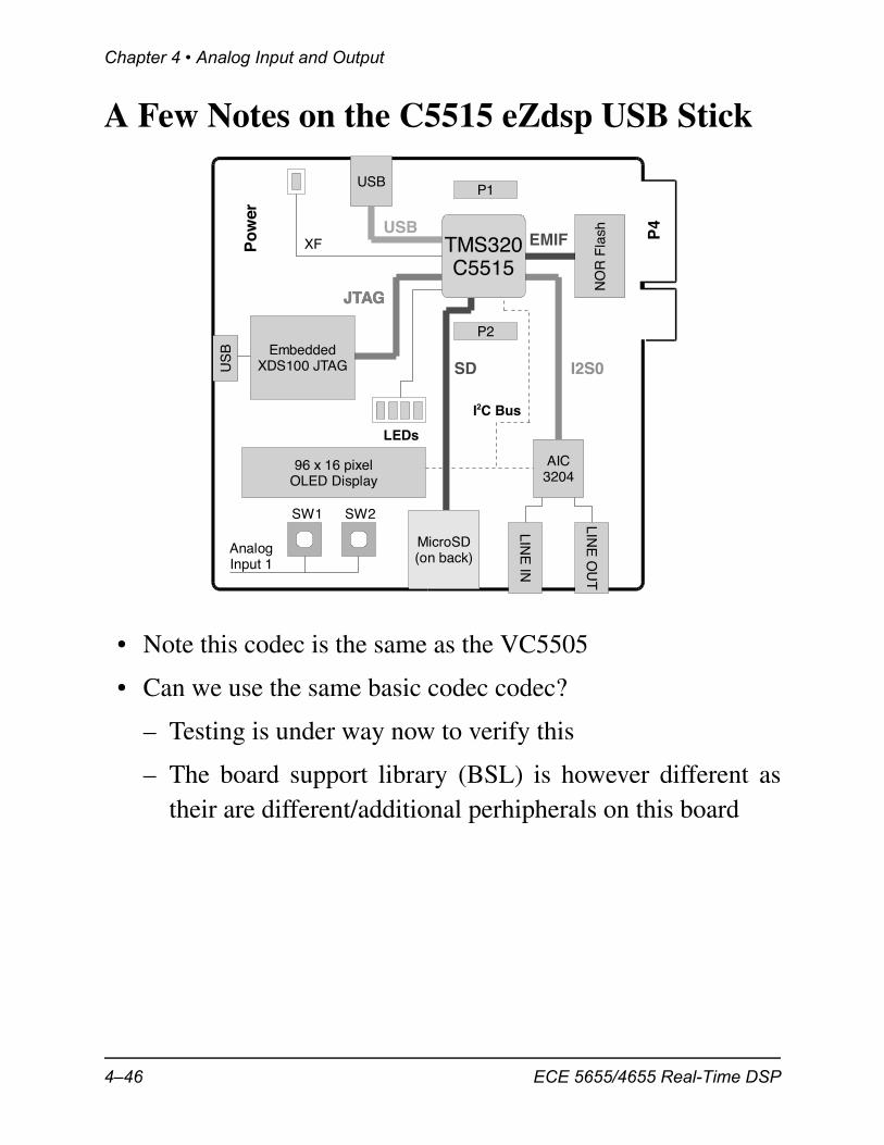
A Few Notes on the C5515 eZdsp USB Stick
• Note this codec is the same as the VC5505
• Can we use the same basic codec codec?
– Testing is under way now to verify this
– The board support library (BSL) is however different astheir are different/additional perhipherals on this board
JTAG
I2C Bus
JTAG
USBTMS320C5515
LINE
IN
LINE
OU
T
96 x 16 pixelOLED Display
P1
P2
LEDs
US
BEMIF
NO
R F
lash
JTAG
I2S0
AIC3204
SD
USB
XFPo
wer
P4
AnalogInput 1
MicroSD(on back)
SW1 SW2
EmbeddedXDS100 JTAG
4–46 ECE 5655/4655 Real-Time DSP
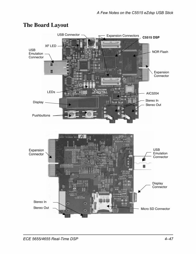
A Few Notes on the C5515 eZdsp USB Stick
The Board Layout
AIC3204
Stereo OutStereo In
NOR Flash
USB ConnectorC5515 DSP
XF LED
Expansion Connectors
ExpansionConnector
LEDs
Pushbuttons
Display
USBEmulationConnector
Stereo Out
Stereo In
Micro SD Connector
ExpansionConnector
Display
USBEmulationConnector
Connector
ECE 5655/4655 Real-Time DSP 4–47
Chapter 4 • Analog Input and Output
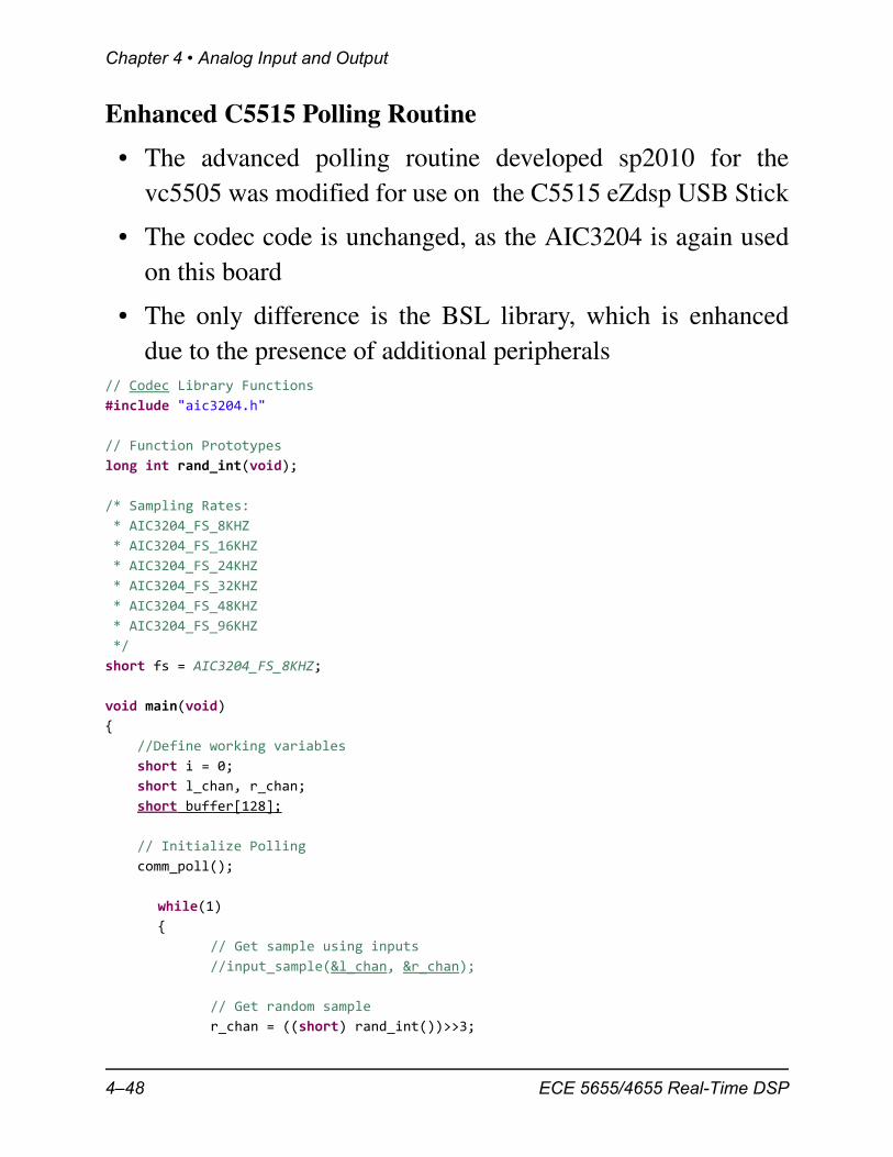
Enhanced C5515 Polling Routine
• The advanced polling routine developed sp2010 for thevc5505 was modified for use on the C5515 eZdsp USB Stick
• The codec code is unchanged, as the AIC3204 is again usedon this board
• The only difference is the BSL library, which is enhanceddue to the presence of additional peripherals
// Codec Library Functions
#include "aic3204.h"
// Function Prototypes
long int rand_int(void);
/* Sampling Rates:
* AIC3204_FS_8KHZ
* AIC3204_FS_16KHZ
* AIC3204_FS_24KHZ
* AIC3204_FS_32KHZ
* AIC3204_FS_48KHZ
* AIC3204_FS_96KHZ
*/
short fs = AIC3204_FS_8KHZ;
void main(void)
{
//Define working variables
short i = 0;
short l_chan, r_chan;
short buffer[128];
// Initialize Polling
comm_poll();
while(1)
{
// Get sample using inputs
//input_sample(&l_chan, &r_chan);
// Get random sample
r_chan = ((short) rand_int())>>3;
4–48 ECE 5655/4655 Real-Time DSP
A Few Notes on the C5515 eZdsp USB Stick
/* Fill buffer */
buffer[i] = r_chan;
i += 1;
if (i == 128) i = 0;
/* Write Digital audio input */
output_sample(l_chan, r_chan);
}
}
//White noise generator for filter noise testing
long int rand_int(void)
{
static long int a = 100001;
a = (a*125) % 2796203;
return a;
}
// aic3204.c
/*
* ECE5655
* Sean O'Brien
* Modified for C5515 eZdsp by Mark Wickert, March 2012
*/
#include "aic3204.h"
#include "usbstk5515.h"
#include "usbstk5515_gpio.h"
#include "usbstk5515_i2c.h"
// Polling Masks
#define AIC3204_I2C_ADDR 0x18
#define XmitL 0x10
#define XmitR 0x20
#define RcvR 0x08
#define RcvL 0x04
// Function Prototypes
static Int16 AIC3204_rget(Uint16 regnum, Uint16* regval);
static Int16 AIC3204_rset(Uint16 regnum, Uint16 regval);
// Sampling rate variable
extern short fs;
ECE 5655/4655 Real-Time DSP 4–49
Chapter 4 • Analog Input and Output
/* ‐‐‐‐‐‐‐‐‐‐‐‐‐‐‐‐‐‐‐‐‐‐‐‐‐‐‐‐‐‐‐‐‐‐‐‐‐‐‐‐‐‐‐‐‐‐‐‐‐‐‐‐‐‐‐‐‐‐‐‐‐‐‐‐‐‐‐‐‐‐‐‐ *
* *
* _AIC3204_rget(regnum, regval) *
* *
* Return value of codec register regnum *
* *
* ‐‐‐‐‐‐‐‐‐‐‐‐‐‐‐‐‐‐‐‐‐‐‐‐‐‐‐‐‐‐‐‐‐‐‐‐‐‐‐‐‐‐‐‐‐‐‐‐‐‐‐‐‐‐‐‐‐‐‐‐‐‐‐‐‐‐‐‐‐‐‐‐ */
static Int16 AIC3204_rget(Uint16 regnum, Uint16* regval)
{
Int16 retcode = 0;
Uint8 cmd[2];
cmd[0] = regnum & 0x007F; // 7‐bit Device Address
cmd[1] = 0;
retcode |= USBSTK5515_I2C_write(AIC3204_I2C_ADDR, cmd, 1);
retcode |= USBSTK5515_I2C_read(AIC3204_I2C_ADDR, cmd, 1);
*regval = cmd[0];
USBSTK5515_wait(10);
return retcode;
}
/* ‐‐‐‐‐‐‐‐‐‐‐‐‐‐‐‐‐‐‐‐‐‐‐‐‐‐‐‐‐‐‐‐‐‐‐‐‐‐‐‐‐‐‐‐‐‐‐‐‐‐‐‐‐‐‐‐‐‐‐‐‐‐‐‐‐‐‐‐‐‐‐‐ *
* *
* _AIC3204_rset(regnum, regval) *
* *
* Set codec register regnum to value regval *
* *
* ‐‐‐‐‐‐‐‐‐‐‐‐‐‐‐‐‐‐‐‐‐‐‐‐‐‐‐‐‐‐‐‐‐‐‐‐‐‐‐‐‐‐‐‐‐‐‐‐‐‐‐‐‐‐‐‐‐‐‐‐‐‐‐‐‐‐‐‐‐‐‐‐ */
static Int16 AIC3204_rset(Uint16 regnum, Uint16 regval)
{
Uint8 cmd[2];
cmd[0] = regnum & 0x007F; // 7‐bit Device Address
cmd[1] = regval; // 8‐bit Register Data
return USBSTK5515_I2C_write(AIC3204_I2C_ADDR, cmd, 2);
}
void comm_poll()
{
/* Define sampling rate parameters */
unsigned char pll_dh, pll_dl, madc, mdac, nadc, ndac;
/* Initialize BSL */
USBSTK5515_init();
4–50 ECE 5655/4655 Real-Time DSP
A Few Notes on the C5515 eZdsp USB Stick
/* Configure Serial Bus */
SYS_EXBUSSEL |= 0x0100; // Configure Serial bus 0 for I2S0
/* Set Sampling Rate */
if(fs == AIC3204_FS_44_1KHZ)
{
// PLL D = 560
pll_dh = 0x02;
pll_dl = 0x30;
// MDAC & MACC = 3
madc = 0x03;
mdac = 0x03;
// NDAC & NADC = 5
nadc = 0x05;
ndac = 0x05;
}
else // 8, 16, 24, 32, 48, 96 KHz
{
// PLL D = 1680
pll_dh = 0x06;
pll_dl = 0x90;
switch(fs) {
case AIC3204_FS_8KHZ:
madc = 0x0C;
mdac = 0x0C;
break;
case AIC3204_FS_16KHZ:
madc = 0x06;
mdac = 0x06;
break;
case AIC3204_FS_24KHZ:
madc = 0x04;
mdac = 0x04;
break;
case AIC3204_FS_32KHZ:
madc = 0x03;
mdac = 0x03;
break;
case AIC3204_FS_48KHZ:
madc = 0x02;
mdac = 0x02;
break;
case AIC3204_FS_96KHZ:
madc = 0x01;
ECE 5655/4655 Real-Time DSP 4–51
Chapter 4 • Analog Input and Output
mdac = 0x01;
break;
}
// NDAC & NADC = 7
nadc = 0x07;
ndac = 0x07;
}
/* Configure AIC3204 */
AIC3204_rset( 0, 0 ); // Select page 1
AIC3204_rset( 1, 1 ); // Reset codec
AIC3204_rset( 0, 1 ); // Point to page 1
AIC3204_rset( 1, 8 ); // Disable crude AVDD generation from DVDD
AIC3204_rset( 2, 1 ); // Enable Analog Blocks, use LDO power
AIC3204_rset( 0, 0 );
/* PLL and Clocks config and Power Up */
AIC3204_rset(27, 0x1d);// BCLK and WCLK is set as o/p to AIC3204(Master)
AIC3204_rset(28, 0x00);// Data ofset = 0
AIC3204_rset(4, 3); // PLL setting: PLLCLK <‐ MCLK, CODEC_CLKIN <‐PLL CLK
AIC3204_rset(6, 0x07);// Set PLL J
AIC3204_rset(7, pll_dh);// PLL setting: D HI_BYTE(5:0)
AIC3204_rset(8, pll_dl);// PLL setting: D LO_BYTE(7:0)
AIC3204_rset(30, 0x88);// For 32 bit clocks per frame in Master mode ONLY
// BCLK=DAC_CLK/N
=(12288000/8) = 1.536MHz = 32*fs
AIC3204_rset(5, 0x91);//PLL setting: Power up PLL, P=1 and R=1
AIC3204_rset(13, 0x00);// DOSR Hi_Byte(1:0) = 0
AIC3204_rset(14, 0x80);// DOSR Lo_Byte(7:0) = 128
AIC3204_rset(20, 0x80);// AOSR (7:0) = 128
AIC3204_rset(11, 0x80 | ndac); // Power up NDAC and set NDAC value
AIC3204_rset(12, 0x80 | mdac); // Power up MDAC and set MDAC value
AIC3204_rset(18, 0x80 | nadc); // Power up NADC and set NADC value
AIC3204_rset(19, 0x80 | madc); // Power up MADC and set MADC value
/* DAC ROUTING and Power Up */
AIC3204_rset( 0, 1 ); // Select page 1
AIC3204_rset( 0x0c, 8 ); // LDAC AFIR routed to HPL
AIC3204_rset( 0x0d, 8 ); // RDAC AFIR routed to HPR
AIC3204_rset( 0, 0 ); // Select page 0
AIC3204_rset( 64, 2 ); // Left vol=right vol
AIC3204_rset( 65, 0 ); // Left DAC gain to 0dB VOL; Right tracks Left
AIC3204_rset( 63, 0xd4 ); // Power up left,right data paths and set channel
AIC3204_rset( 0, 1 ); // Select page 1
AIC3204_rset( 0x10, 10 ); // Unmute HPL , 10dB gain
AIC3204_rset( 0x11, 10 ); // Unmute HPR , 10dB gain
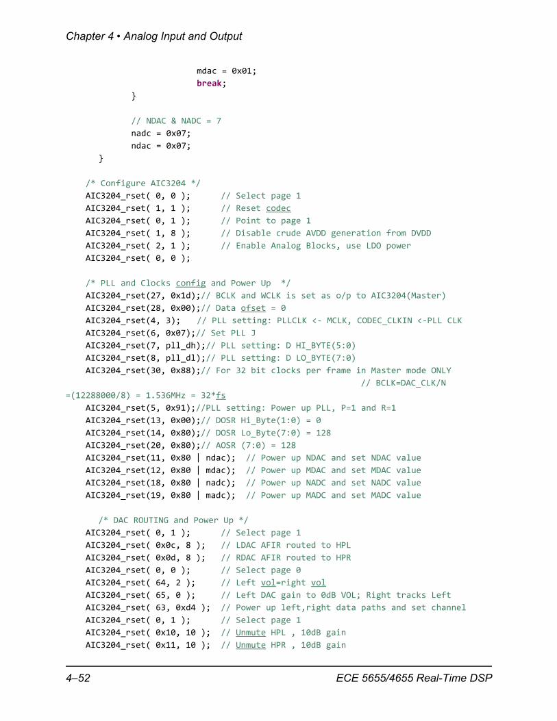
4–52 ECE 5655/4655 Real-Time DSP
A Few Notes on the C5515 eZdsp USB Stick
AIC3204_rset( 9, 0x30 ); // Power up HPL,HPR
AIC3204_rset( 0, 0 ); // Select page 0
USBSTK5515_wait( 100 ); // wait
/* ADC ROUTING and Power Up */
AIC3204_rset( 0, 1 ); // Select page 1
AIC3204_rset( 0x34, 0x30 );// STEREO 1 Jack
// IN2_L to LADC_P through 40 kohm
AIC3204_rset( 0x37, 0x30 );// IN2_R to RADC_P through 40 kohmm
AIC3204_rset( 0x36, 3 ); // CM_1 (common mode) to LADC_M through 40 kohm
AIC3204_rset( 0x39, 0xc0 );// CM_1 (common mode) to RADC_M through 40 kohm
AIC3204_rset( 0x3b, 0 ); // MIC_PGA_L unmute
AIC3204_rset( 0x3c, 0 ); // MIC_PGA_R unmute
AIC3204_rset( 0, 0 ); // Select page 0
AIC3204_rset( 0x51, 0xc0 );// Powerup Left and Right ADC
AIC3204_rset( 0x52, 0 ); // Unmute Left and Right ADC
AIC3204_rset( 0, 0 );
USBSTK5515_wait( 100 ); // Wait
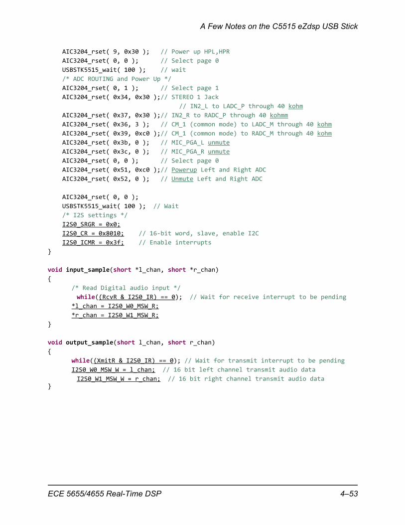
/* I2S settings */
I2S0_SRGR = 0x0;
I2S0_CR = 0x8010; // 16‐bit word, slave, enable I2C
I2S0_ICMR = 0x3f; // Enable interrupts
}
void input_sample(short *l_chan, short *r_chan)
{
/* Read Digital audio input */
while((RcvR & I2S0_IR) == 0); // Wait for receive interrupt to be pending
*l_chan = I2S0_W0_MSW_R;
*r_chan = I2S0_W1_MSW_R;
}
void output_sample(short l_chan, short r_chan)
{
while((XmitR & I2S0_IR) == 0); // Wait for transmit interrupt to be pending
I2S0_W0_MSW_W = l_chan; // 16 bit left channel transmit audio data
I2S0_W1_MSW_W = r_chan; // 16 bit right channel transmit audio data}
ECE 5655/4655 Real-Time DSP 4–53
Chapter 4 • Analog Input and Output
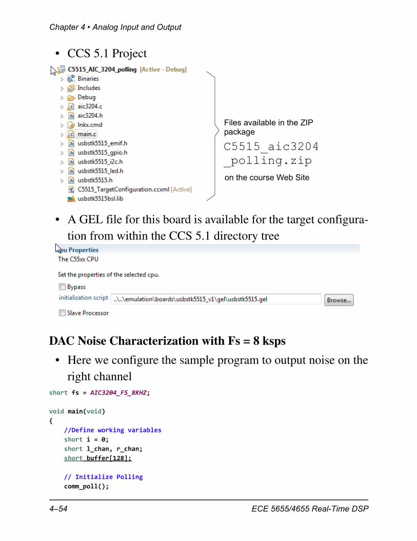
• CCS 5.1 Project
• A GEL file for this board is available for the target configura-tion from within the CCS 5.1 directory tree
DAC Noise Characterization with Fs = 8 ksps
• Here we configure the sample program to output noise on theright channel
short fs = AIC3204_FS_8KHZ;
void main(void)
{
//Define working variables
short i = 0;
short l_chan, r_chan;
short buffer[128];
// Initialize Polling
comm_poll();
Files available in the ZIPpackage
C5515_aic3204
on the course Web Site
_polling.zip
4–54 ECE 5655/4655 Real-Time DSP
A Few Notes on the C5515 eZdsp USB Stick
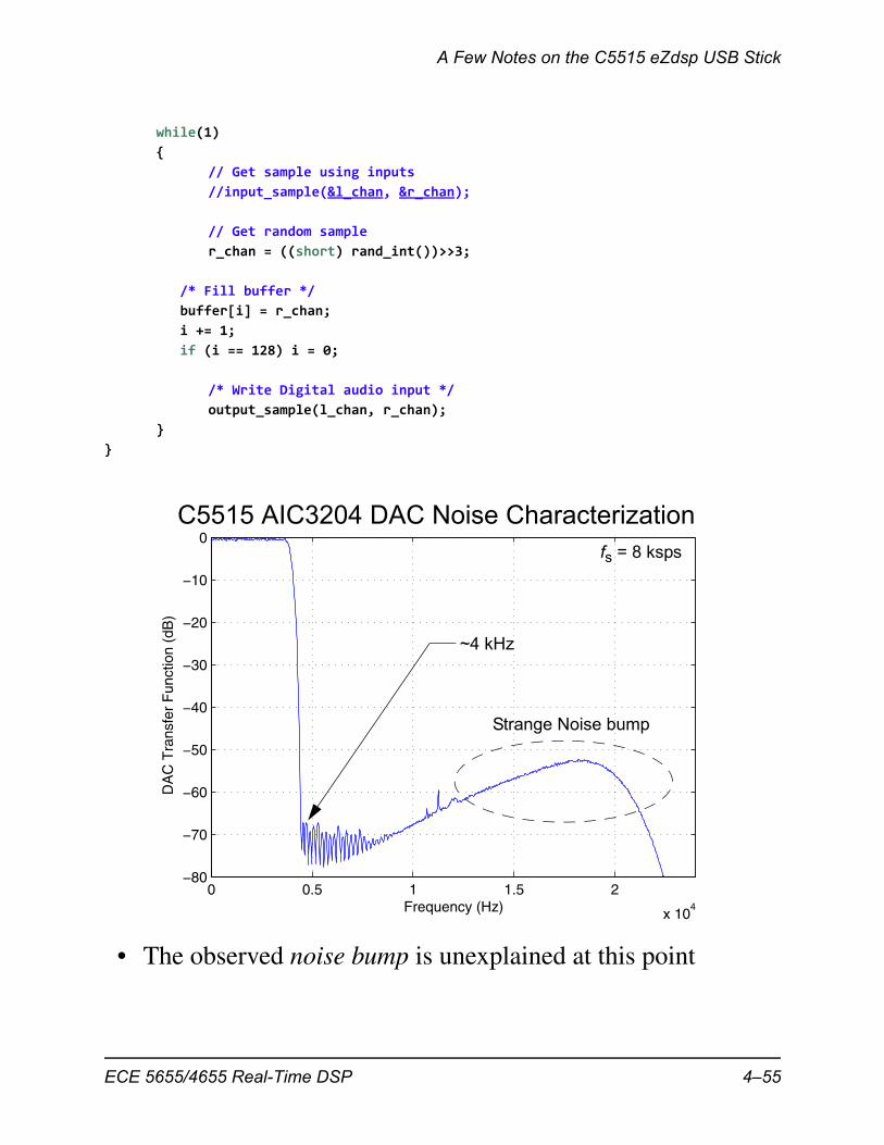
while(1)
{
// Get sample using inputs
//input_sample(&l_chan, &r_chan);
// Get random sample
r_chan = ((short) rand_int())>>3;
/* Fill buffer */
buffer[i] = r_chan;
i += 1;
if (i == 128) i = 0;
/* Write Digital audio input */
output_sample(l_chan, r_chan);
}
}
• The observed noise bump is unexplained at this point
0 0.5 1 1.5 2
x 104
−80
−70
−60
−50
−40
−30
−20
−10
0
Frequency (Hz)
DA
C T
rans
fer
Fun
ctio
n (d
B)
C5515 AIC3204 DAC Noise Characterizationfs = 8 ksps
~4 kHz
Strange Noise bump
ECE 5655/4655 Real-Time DSP 4–55
Chapter 4 • Analog Input and Output
4–56 ECE 5655/4655 Real-Time DSP