Embed Size (px)
Citation preview

Analog input and output
Embedded Systems Design Course Applying the mbed microcontroller
1
These course notes are written by R.Toulson (Anglia Ruskin University) and T.Wilmshurst (University of Derby). (c) ARM 2012
These course notes accompany the textbook “Fast and effective embedded system design : Applying the ARM mbed”

Analog input and output
• Introduction to analog signals and data
• Concepts of analog-to-digital conversion
• Analog inputs on the mbed
• Reading and logging data from analog inputs
• Concepts of digital-to-analog conversion
• Analog output with the mbed
• Generating output waveforms
2

Introduction to analog data
• Microcontrollers are often required to interface with analog signals
• They must be able to convert input analog signals, for example from microphone or temperature sensor, to digital data
• They must also be able to convert digital signals to analog form, for example if driving a loudspeaker or dc motor
• We will first consider conversion from analog-to-digital, before later looking at digital-to-analog conversion
3

Concepts of analog-to-digital conversion
• An analog-to-digital convertor (ADC) is an electronic circuit whose digital output is proportional to its analog input
• Effectively it "measures" the input voltage, and gives a binary output number proportional to its size
• The input range of the ADC is usually determined by the value of a voltage reference
4

Concepts of analog-to-digital conversion
• The conversion is started by a digital input, called here SC
• It takes finite time, and the ADC signals with the EOC line when the conversion is complete
• The resulting data can then be enabled onto a data bus using the OE line
5
Analogue Digital
Output
Analogue
Input
SC EOC OE
(n bits)
+
-
(Start
Convert)
(End of
Conversion)
(Output Enable)
Voltage Reference
+
Example Control Lines
to DigitalConverter
Analogue Digital
Output
Analogue
Input
SC EOC OE
(n bits)
+
-
(Start
Convert)
(End of
Conversion)
(Output Enable)
Voltage Reference
+
Example Control Lines
to DigitalConverter

Concepts of analog-to-digital conversion
6
• The `staircase’ visible in a 3-bit ADC
001
010
011
100
101
110
111
Vmax
DigitalOutput
Analogue
Input
000
0
001
010
011
100
101
110
111
Vmax
DigitalOutput
Analogue
Input
000
0

Concepts of analog-to-digital conversion
Resolution and quantisation
• By converting an analog signal to digital, we are effectively approximating it, as any one digital output value has to represent a very small range of analog input voltages, i.e. the width of any of the steps on the “staircase” n.
• If we want to convert an analog signal that has a range 0-3.3 V to an 8-bit digital signal, then there are 256 (i.e. 28) distinct output values. Each step has a width of 3.3/256 = 12.89 mV, and the worst case quantisation error is 6.45mV.
• The mbed uses a 12-bit ADC. This leads to a step width of 3.3/212, or 0.8 mV; the worst case quantisation error is therefore 0.4 mV.
7

Concepts of analog-to-digital conversion
Sampling frequency
• When converting an analog signal to digital, we repeatedly take a ‘sample’ and quantise this to the accuracy defined by the resolution of our ADC.
• The more samples taken, the more accurate the digital data will be. Samples are normally taken at fixed periods (i.e., every 0.2ms) and define the rate of sampling by the sampling frequency (the number of samples taken per second).
8

Concepts of analog-to-digital conversion
Sampling frequency
• The sample frequency needs to be chosen with respect to the rate of which the sampled data is changing. If the sample frequency is too low then rapid changes in the analog signal may not be obvious in the resulting digital data.
• For this reason the Nyquist sampling criterion states that the sampling frequency must be at least double that of the highest frequency of interest.
9
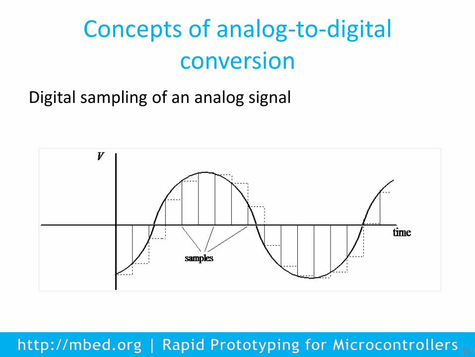
Concepts of analog-to-digital conversion
10
Digital sampling of an analog signal
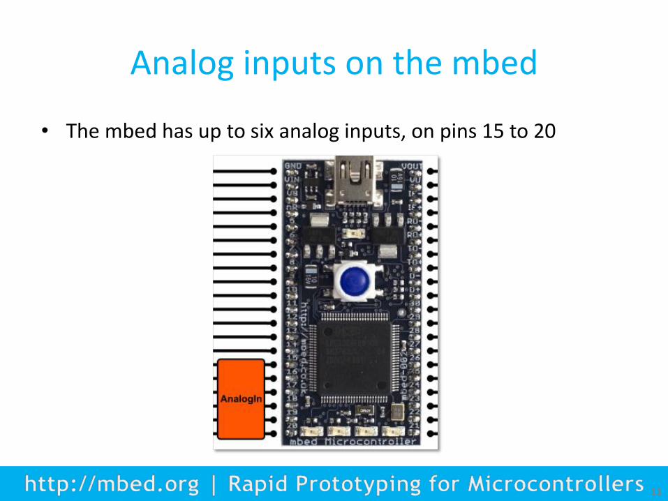
Analog inputs on the mbed
• The mbed has up to six analog inputs, on pins 15 to 20
11

Analog-to-digital conversion on the mbed
12
The library functions are shown in the table below
AnalogIn An analog input, used for reading the voltage on a pin
Functions Usage
AnalogIn Create an AnalogIn, connected to the specified pin
read Read the input voltage, represented as a float in the range [0.0, 1.0]
read_u16 Read the input voltage, represented as an unsigned short in the range [0x0, 0xFFFF]
operator float operator float An operator shorthand for read()

Reading and logging data from analog inputs
• Exercise 1: Attach a potentiometer output to mbed pin 20. – Start a new mbed project and enter the code below.
– This code will continuously display the analog input value when used with a host PC terminal application.
13
//Reads input through the ADC, and transfers to PC terminal
#include "mbed.h"
Serial pc(USBTX, USBRX);
AnalogIn Ain(p20);
float ADCdata;
int main() {
pc.printf("ADC Data Values... \n\r");
while (1) {
ADCdata=Ain;
pc.printf("%f \n\r",ADCdata);
wait (0.5);
}
}

Reading data from analog inputs
• Exercise 2: Using the four onboard mbed LEDs, write a program that will use a potentiometer input on pin 20 to continuously control how many LEDs are on. Use the following chart to define the LED control:
14
Analog input value x LED1 LED2 LED3 LED4
x <= 0.2 0 0 0 0
0.2 < x <= 0.4 1 0 0 0
0.4 < x <= 0.6 1 1 0 0
0.6 < x <= 0.8 1 1 1 0
0.8 < x <= 1.0 1 1 1 1

Concepts of digital-to-analog conversion
• We can represent the digital-to-analog convertor (DAC) as a block diagram with a digital input, D, and an analog output, vo
• The output range of the DAC, vr , is the difference between the maximum and minimum output voltages, i.e.
vr = vmax - vmin
• The particular output range is usually defined by a fixed voltage reference supplied to the DAC
• Digital control lines allow a microcontroller to setup and communicate with the DAC
15

Concepts of digital-to-analog conversion
For each digital value input to the DAC, there is a corresponding analog output value given by
16
(n-bit Digital
input)
(Analog
Output)
+
-
Voltage Reference+
Control Lines
Digital to AnalogueConverter
D VO
(n-bit Digital
input)
(Analog
Output)
+
-
Voltage Reference+
Control Lines
Digital to AnalogueConverter
D VO

Concepts of digital-to-analog conversion
• The mbed’s LPC1768 chip has a 10-bit DAC (i.e. n=10)
• The mbed uses its own 3.3 V power supply as voltage reference
• There will therefore be 2n steps in the mbed DAC output characteristic, i.e. 1024
• The step size, or resolution, is therefore be 3.3/1024, i.e. 3.2mV per bit
17

Digital-to-analog conversion on the mbed
18
• The mbed has a single analog output on pin 18

Digital to analog conversion on the mbed
19
The library functions are shown in the table below
AnalogOut An analog output, used for setting the voltage on a pin
Functions Usage
AnalogOut Create an AnalogOut connected to the specified pin
write Set the output voltage, specified as a percentage (float)
write_u16 Set the output voltage, represented as an unsigned short in the range [0x0, 0xFFFF]
read Return the current output voltage setting, measured as a percentage (float)
operator= An operator shorthand for write()
operator float() An operator shorthand for read()

Analog output with the mbed
• The mbed analog output on pin 18 is configured by the following declaration:
20
• By default, the analog object takes a floating point number between 0.0 and 1.0 and outputs this to pin 18
• The actual output voltage on pin 18 is between 0V and 3.3V, so the floating point number that is output as a voltage is scaled by a factor of 3.3
AnalogOut Aout(p18);

Analog output with the mbed
• Exercise 3: compile the program shown below and, using an oscilloscope, familiarise yourself with the analog output.
21
#include "mbed.h"
int main() {
AnalogOut Aout(p18);
while(1) {
Aout=0.25; // 0.25*3.3V = 0.825V
wait(1);
Aout=0.5; // 0.5*3.3V = 1.65V
wait(1);
Aout=0.75; // 0.75*3.3V = 2.475V
wait(1);
}
}

Analog output with the mbed
• Exercise 4: Now make a sawtooth wave and view it on an oscilloscope.
• Create a new program and enter the following code
22
//Sawtooth waveform on DAC output to view on oscilloscope
#include "mbed.h"
AnalogOut Aout(p18);
float i;
int main() {
while(1)
{
for (i=0;i<1;i=i+0.1)
{
Aout=i;
wait(0.001);
}
}
}

Analog output with the mbed
• Exercise 5: Modify your code to create a smoother sawtooth wave, by implementing finer steps in the for loop:
23
• Exercise 6: Create a smooth triangular wave by implementing a second loop to count down also:

Summary
24
• Introduction to analog signals and data
• Concepts of analog-to-digital conversion
• Analog inputs on the mbed
• Reading and logging data from analog inputs
• Concepts of digital-to-analog conversion
• Analog output with the mbed
• Generating output waveforms