Embed Size (px)
Citation preview

8/22/2019 Analog Input Card R200
http://slidepdf.com/reader/full/analog-input-card-r200 1/80
Honeywell Process Solutions
Isolated Analog Input Module
2MLF-AD4S
User's Guide
ML200-IAI
R200
Mar 2010
Release 200
Honeywell
8/22/2019 Analog Input Card R200
http://slidepdf.com/reader/full/analog-input-card-r200 2/80
ii Isolated Analog Input Module 2MLF-AD4S User's Guide R200Honeywell Mar 2010
Notices and Trademarks
Copyright 2010 by Honeywell International Sárl.Release 200 March, 2010
While this information is presented in good faith and believed to be accurate, Honeywell disclaimsthe implied warranties of merchantability and fitness for a particular purpose and makes noexpress warranties except as may be stated in its written agreement with and for its customers.
In no event is Honeywell liable to anyone for any indirect, special or consequential damages. The
information and specifications in this document are subject to change without notice.
Honeywell, PlantScape, Experion PKS, and TotalPlant are registered trademarks of HoneywellInternational Inc.
Other brand or product names are trademarks of their respective owners.
Honeywell Process Solutions
1860 W. Rose Garden Lane
Phoenix, AZ 85027 USA
1-800 822-7673
8/22/2019 Analog Input Card R200
http://slidepdf.com/reader/full/analog-input-card-r200 3/80
R200 Isolated Analog Input Module 2MLF-AD4S User's Guide iiiMar 2010 Honeywell
About This Document
This document describes how to install and configure the 2MLF-AD4S, isolated analog input
module.
Release Information
Document Name DocumentID
ReleaseNumber
PublicationDate
2MLF-AD4S User's Guide ML200 ML200-IAI 200 Mar 2010
References
The following list identifies all documents that may be source of reference for material discussedin this publication.
Document Title
SoftMaster User’s Guide
8/22/2019 Analog Input Card R200
http://slidepdf.com/reader/full/analog-input-card-r200 4/80
Support and Other Contacts
iv Isolated Analog Input Module 2MLF-AD4S User's Guide R200Honeywell Mar 2010
Support and Other Contacts
United States and Canada
Contact:Phone:
Fascimile:Mail:
Honeywell Solution Support Center 1-800-822-7673Calls are answered by dispatcher between 6:00 am and 4:00 pmMountain Standard Time. Emergency calls outside normal working hoursare received by an answering service and returned within one hour.1-973-455-5000Honeywell TAC, MS L171860 W. Garden LanePhoenix, AZ, 85027 USA
Europe, Middle East, and Africa (EMEA)
Contact:Phone:Fascimile:Mail:
Honeywell TAC-EMEA+32-2-728-2345+32-2-728-2696TAC-BE02Hermes PlazaHermeslaan, 1HB-1831 Diegem, Belgium
Pacific
Contact:Phone:
Fascimile:Mail:
Email:
Honeywell Global TAC – Pacific1300-364-822 (toll free within Australia)
+61-8-9362-9559 (outside Australia)+61-8-9362-9564Honeywell Limited Australia5 Kitchener WayBurswood 6100, Western [email protected]
India
Contact:Phone:Fascimile:Mail:
Email:
Honeywell Global TAC – India+91-20- 6603-9400+91-20- 6603-9800Honeywell Automation India Ltd56 and 57, Hadapsar Industrial EstateHadapsar, Pune –411 013, India
8/22/2019 Analog Input Card R200
http://slidepdf.com/reader/full/analog-input-card-r200 5/80
Support and Other Contacts
R200 Isolated Analog Input Module 2MLF-AD4S User's Guide vMar 2010 Honeywell
Korea
Contact:Phone:Fascimile:Mail:
Email:
Honeywell Global TAC – Korea+82-2-799-6317+82-2-792-9015Honeywell Co., Ltd4F, Sangam IT Tower 1590, DMC Sangam-dong, Mapo-guSeoul, 121-836, [email protected]
People’s Republic o f China
Contact:Phone:
Mail:
Email:
Honeywell Global TAC – China+86- 21-2219-6888800-820-0237400-820-0386Honeywell (China) Co., Ltd33/F, Tower A, City Center, 100 Zunyi Rd.Shanghai 200051, People’s Republic of [email protected]
Singapore
Contact:Phone:Fascimile:
Mail:
Email:
Honeywell Global TAC – South East Asia+65-6580-3500+65-6580-3501+65-6445-3033
Honeywell Private LimitedHoneywell Building17, Changi Business Park Central 1Singapore [email protected]
Taiwan
Contact:Phone:Fascimile:Mail:
Email:
Honeywell Global TAC – Taiwan+886-7-536-2567+886-7-536-2039Honeywell Taiwan Ltd.17F-1, No. 260, Jhongshan 2nd Road.Cianjhen DistrictKaohsiung, Taiwan, ROC
8/22/2019 Analog Input Card R200
http://slidepdf.com/reader/full/analog-input-card-r200 6/80
Support and Other Contacts
vi Isolated Analog Input Module 2MLF-AD4S User's Guide R200Honeywell Mar 2010
Japan
Contact:Phone:Fascimile:Mail:
Email:
Honeywell Global TAC – Japan+81-3-6730-7160+81-3-6730-7228Honeywell Japan Inc.New Pier Takeshiba, South Tower Building,20th Floor, 1-16-1 Kaigan, Minato-ku,Tokyo 105-0022, [email protected]
Elsewhere
Call your nearest Honeywell office.
World Wide Web
Honeywell Solution Support Online:
http://www.honeywell.com/ps
Training Classes
Honeywell Automation College:
http://www.automationcollege.com
8/22/2019 Analog Input Card R200
http://slidepdf.com/reader/full/analog-input-card-r200 7/80
Symbol Definitions
Symbol Definitions
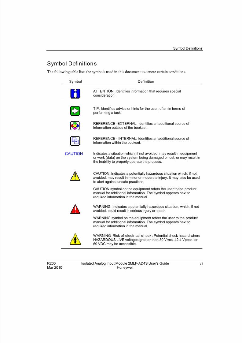
The following table lists the symbols used in this document to denote certain conditions.
Symbol Definition
ATTENTION: Identifies information that requires specialconsideration.
TIP: Identifies advice or hints for the user, often in terms of performing a task.
REFERENCE -EXTERNAL: Identifies an additional source of information outside of the bookset.
REFERENCE - INTERNAL: Identifies an additional source of information within the bookset.
CAUTION Indicates a situation which, if not avoided, may result in equipmentor work (data) on the system being damaged or lost, or may result inthe inability to properly operate the process.
CAUTION: Indicates a potentially hazardous situation which, if notavoided, may result in minor or moderate injury. It may also be usedto alert against unsafe practices.
CAUTION symbol on the equipment refers the user to the productmanual for additional information. The symbol appears next torequired information in the manual.
WARNING: Indicates a potentially hazardous situation, which, if notavoided, could result in serious injury or death.
WARNING symbol on the equipment refers the user to the productmanual for additional information. The symbol appears next torequired information in the manual.
WARNING, Risk of electrical shock : Potential shock hazard where
HAZARDOUS LIVE voltages greater than 30 Vrms, 42.4 Vpeak, or 60 VDC may be accessible.
R200 Isolated Analog Input Module 2MLF-AD4S User's Guide viiMar 2010 Honeywell
8/22/2019 Analog Input Card R200
http://slidepdf.com/reader/full/analog-input-card-r200 8/80
Symbol Definitions
viii Isolated Analog Input Module 2MLF-AD4S User's Guide R200Honeywell Mar 2010
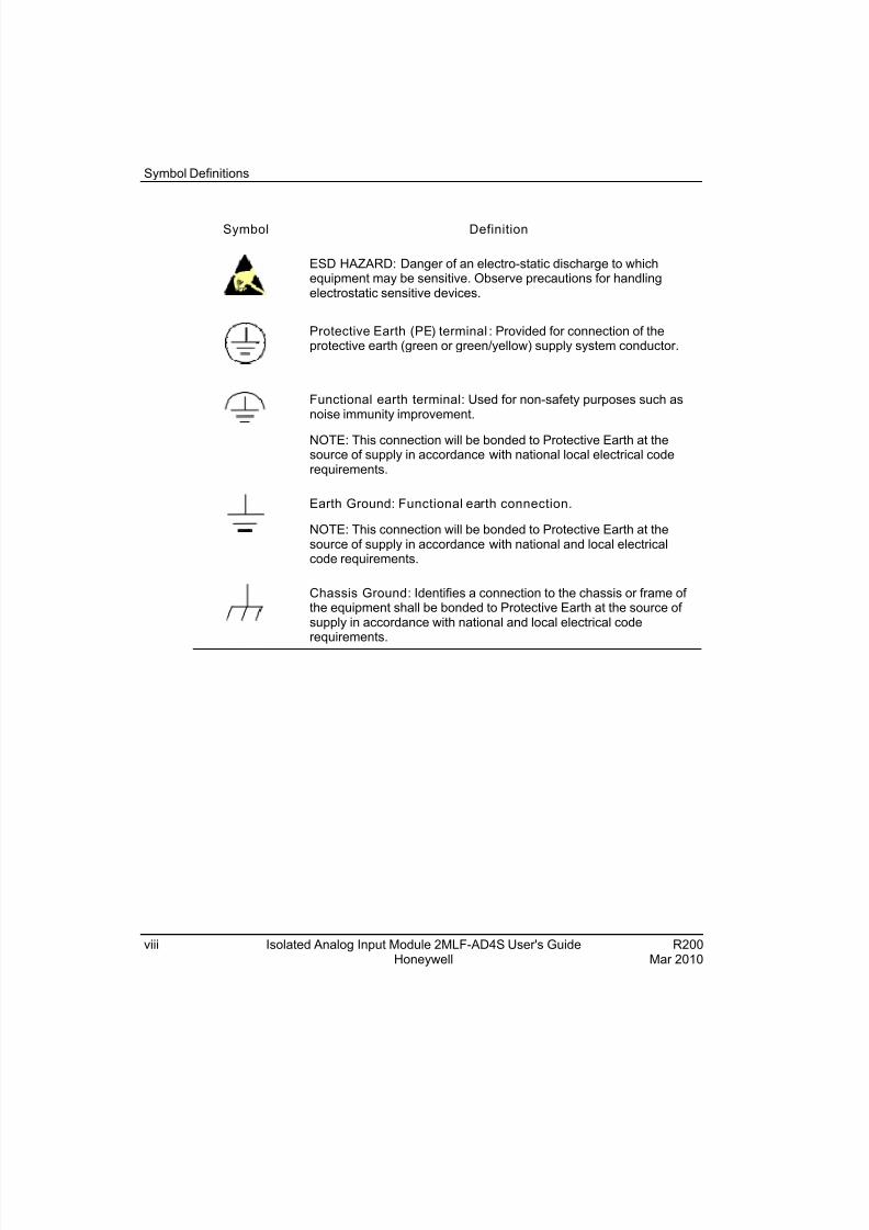
Symbol Definition
ESD HAZARD: Danger of an electro-static discharge to whichequipment may be sensitive. Observe precautions for handlingelectrostatic sensitive devices.
Protective Earth (PE) terminal : Provided for connection of theprotective earth (green or green/yellow) supply system conductor.
Functional earth terminal: Used for non-safety purposes such asnoise immunity improvement.
NOTE: This connection will be bonded to Protective Earth at thesource of supply in accordance with national local electrical coderequirements.
Earth Ground: Functional earth connection.
NOTE: This connection will be bonded to Protective Earth at thesource of supply in accordance with national and local electricalcode requirements.
Chassis Ground: Identifies a connection to the chassis or frame of the equipment shall be bonded to Protective Earth at the source of supply in accordance with national and local electrical coderequirements.
8/22/2019 Analog Input Card R200
http://slidepdf.com/reader/full/analog-input-card-r200 9/80
R200 Isolated Analog Input Module 2MLF-AD4S User's Guide ixMar 2010 Honeywell
Contents
1. INTRODUCTION ..........................................................................11
1.1 Overview ........................................................................................................ 11
1.2 Features ......................................................................................................... 11
2. SPECIFICATIONS........................................................................13
2.1 Performance specif ications ......................................................................... 13 2.2 Part names and funct ions ............................................................................ 16
2.3 Characterist ics of A/D convers ion .............................................................. 18 How to select the range of the A/D conversion? ..................................................................18 Characteristics of the A/D conversion ..................................................................................19 Digital values corresponding to each input...........................................................................20
3. INSTALLATION AND WIRING ....................................................23
3.1 Wiring .............................................................................................................23 Precautions for wiring...........................................................................................................23 Wiring examples...................................................................................................................23
3.2 Instal lat ion .....................................................................................................28 Installation environment .......................................................................................................28 Precautions for handling ......................................................................................................29
4. CONFIGURATION .......................................................................31
4.1 Conf iguration of analog input module ........................................................31 Functions of A/D conversion ................................................................................................31 Sampling processing............................................................................................................31
Average processing .............................................................................................................32 Alarm processing .................................................................................................................36 Detection of input disconnection ..........................................................................................37
4.2 Internal memory conf iguration ....................................................................39
Special module registration for 2MLF-AD4S ........................................................................39 Internal memory of the A/D module (2MLF-AD4S)...............................................................43
5. OPERATION AND MONITORING ...............................................53
8/22/2019 Analog Input Card R200
http://slidepdf.com/reader/full/analog-input-card-r200 10/80
Contents
x Isolated Analog Input Module 2MLF-AD4S User's Guide R200Honeywell Mar 2010
5.1 Setting the operation parameters ................................................................53 Parameters of the 2MLF-AD4S module .............................................................................. 53 The procedure of setting parameters with SoftMaster......................................................... 54
5.2 Special module registration .........................................................................59 Registering special module ................................................................................................. 59 Save variables..................................................................................................................... 60 View variables ..................................................................................................................... 60
5.3 Monitor ing special modules .........................................................................62 Monitoring 2MLF AD4S....................................................................................................... 62 Special module monitoring.................................................................................................. 64
6. PROGRAMMING ......................................................................... 67
6.1 Setting the operating parameters ................................................................67 Reading the operation parameters (GET, GETP instruction) .............................................. 67 Writing the operation parameters (PUT, PUTP instruction)) ................................................ 68
6.2 Basic program................................................................................................70 Configuring the I/O parameters ........................................................................................... 70 Setting the parameters in a scan program .......................................................................... 72
7. TROUBLESHOOTING................................................................. 73
7.1 Checking operation status............................................................................73 Error codes.......................................................................................................................... 73
7.2 Troubleshoot ing ............................................................................................74 RUN LED flickers ................................................................................................................ 74 RUN LED is OFF................................................................................................................. 75 CPU module cannot read A/D converted value ................................................................... 76 Incorrect digital value .......................................................................................................... 76 H/W error of A/D conversion module................................................................................... 77 Checking operation status from SoftMaster system monitoring .......................................... 77
7.3 Dimensions ....................................................................................................78 2MLF-AD4S dimensions ..................................................................................................... 78
8/22/2019 Analog Input Card R200
http://slidepdf.com/reader/full/analog-input-card-r200 11/80
R200 Isolated Analog Input Module 2MLF-AD4S User's Guide 11Mar 2010 Honeywell
1. Introduction
1.1 Overview
The 2MLF-AD4S isolated analog input module converts analog signal (voltage or current
input) to signed 16-bit binary data of digital value.
1.2 Features
The following are the features of 2MLF-AD4S isolated analog input module.
The channels of the 2MLF-AD4S isolated analog input module are isolated from
each other. This ensures a high reliability without mutual interference.
High resolution of 1/64000.
Provides a high conversion accuracy of ±0.05 % (ambient temperature of 25°). It
also ensures a temperature coefficient accuracy of 40ppm/°.
Enables setting/monitoring of operation parameters. Configure the operation
parameter settings from the I/O Parameters Setting window in SoftMaster. In
addition, use the Special Module Monitoring function in SoftMaster to monitor theA/D conversion value.
Provides three formats of digital output data as below:
Signed Value: -32000 ~ 32000
Precise Value: Refer to section Performance specifications, for analog input
range.
Percentile Value: 0 ~ 10000
Provides an input disconnection detection function. This detects the disconnection of input circuit when 1 ~ 5V (4 ~ 20mA) of analog input signal range is used.

8/22/2019 Analog Input Card R200
http://slidepdf.com/reader/full/analog-input-card-r200 12/80
1. Introduction1.2. Features
12 Isolated Analog Input Module 2MLF-AD4S User's Guide R200Honeywell Mar 2010
8/22/2019 Analog Input Card R200
http://slidepdf.com/reader/full/analog-input-card-r200 13/80
R200 Isolated Analog Input Module 2MLF-AD4S User's Guide 13Mar 2010 Honeywell
2. Specifications
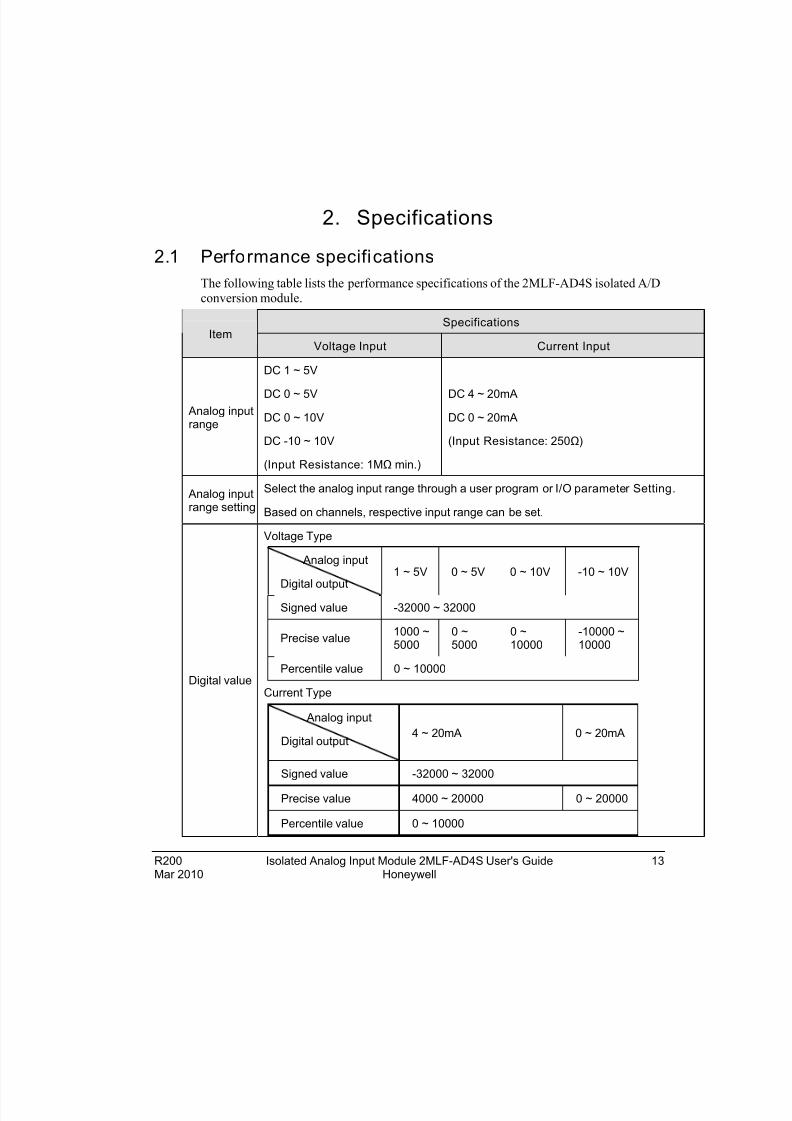
2.1 Performance specifications
The following table lists the performance specifications of the 2MLF-AD4S isolated A/D
conversion module.
SpecificationsItem
Voltage Input Current Input
Analog inputrange
DC 1 ~ 5V
DC 0 ~ 5V
DC 0 ~ 10V
DC -10 ~ 10V
(Input Resistance: 1MΩ min.)
DC 4 ~ 20mA
DC 0 ~ 20mA
(Input Resistance: 250Ω)
Analog inputrange setting
Select the analog input range through a user program or I/O parameter Setting.
Based on channels, respective input range can be set.
Digital value
Voltage Type
Analog input
Digital output
1 ~ 5V 0 ~ 5V 0 ~ 10V -10 ~ 10V
Signed value -32000 ~ 32000
Precise value1000 ~5000
0 ~5000
0 ~10000
-10000 ~10000
Percentile value 0 ~ 10000
Current Type
Analog input
Digital output4 ~ 20mA 0 ~ 20mA
Signed value -32000 ~ 32000
Precise value 4000 ~ 20000 0 ~ 20000
Percentile value 0 ~ 10000
8/22/2019 Analog Input Card R200
http://slidepdf.com/reader/full/analog-input-card-r200 14/80
2. Specifications2.1. Performance specifications
14 Isolated Analog Input Module 2MLF-AD4S User's Guide R200Honeywell Mar 2010
SpecificationsItem
Voltage Input Current Input
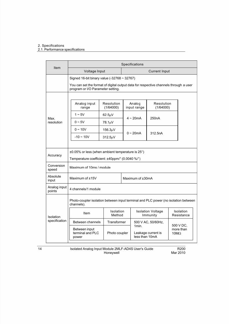
Signed 16-bit binary value (-32768 ~ 32767)
You can set the format of digital output data for respective channels through a user program or I/O Parameter setting.
Max.resolution
Analog inputrange
Resolution(1/64000)
Analoginput range
Resolution(1/64000)
1 ~ 5V 62.5V
0 ~ 5V 78.1V
4 ~ 20mA 250nA
0 ~ 10V 156.3V
-10 ~ 10V 312.5V
0 ~ 20mA 312.5n A
Accuracy±0.05% or less (when ambient temperature is 25°)
Temperature coefficient: ±40ppm/° (0.0040 %/°)
Conversion
speed
Maximum of 10ms / module
Absoluteinput
Maximum of ±15V Maximum of ±30mA
Analog inputpoints
4 channels/1 module
Isolationspecification
Photo-coupler isolation between input terminal and PLC power (no isolation betweenchannels).
ItemIsolationMethod
Isolation VoltageImmunity
IsolationResistance
Between channels Transformer
Between inputterminal and PLCpower
Photo coupler
500 V AC, 50/60Hz,
1min.
Leakage current isless than 10mA
500 V DC,more than
10M
8/22/2019 Analog Input Card R200
http://slidepdf.com/reader/full/analog-input-card-r200 15/80
2. Specifications2.1. Performance specifications
R200 Isolated Analog Input Module 2MLF-AD4S User's Guide 15Mar 2010 Honeywell
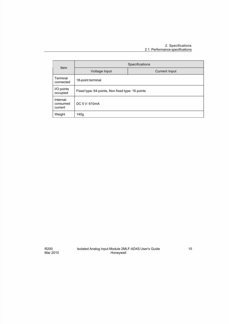
SpecificationsItem
Voltage Input Current Input
Terminalconnected
18-point terminal
I/O pointsoccupied
Fixed type: 64 points, Non fixed type: 16 points
Internal-consumedcurrent
DC 5 V: 610mA
Weight 140g
8/22/2019 Analog Input Card R200
http://slidepdf.com/reader/full/analog-input-card-r200 16/80
2. Specifications2.2. Part names and functions
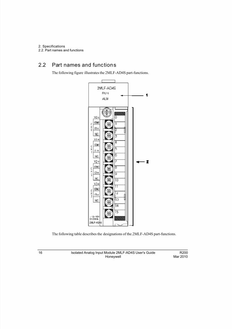
2.2 Part names and functions
The following figure illustrates the 2MLF-AD4S part-functions.
The following table describes the designations of the.2MLF-AD4S part-functions.
16 Isolated Analog Input Module 2MLF-AD4S User's Guide R200Honeywell Mar 2010
8/22/2019 Analog Input Card R200
http://slidepdf.com/reader/full/analog-input-card-r200 17/80
2. Specifications2.2. Part names and functions
R200 Isolated Analog Input Module 2MLF-AD4S User's Guide 17Mar 2010 Honeywell
No Description
Status Display LED1
RUN:
On: In normal operation
Flickering: Error occurs (For more information, refer to section Error codes)
Off : DC 5V disconnected or 2MLF-AD4S module error
ALM:
Flickering: Alarm detected (process alarm, rate of change alarm set bySoftMaster)
OFF: In normal operation
Terminal2
Analog input terminal, whose respective channels can be connectedwith external devices.
8/22/2019 Analog Input Card R200
http://slidepdf.com/reader/full/analog-input-card-r200 18/80
2. Specifications2.3. Characteristics of A/D conversion
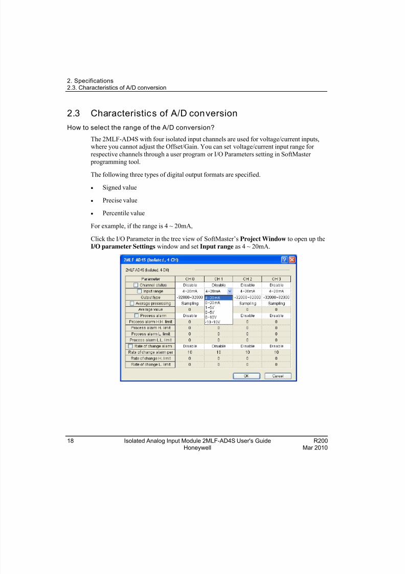
2.3 Characteristics of A/D conversion
How to select the range of the A/D conversion?
The 2MLF-AD4S with four isolated input channels are used for voltage/current inputs,where you cannot adjust the Offset/Gain. You can set voltage/current input range for
respective channels through a user program or I/O Parameters setting in SoftMaster
programming tool.
The following three types of digital output formats are specified.
Signed value
Precise value
Percentile value
For example, if the range is 4 ~ 20mA,
Click the I/O Parameter in the tree view of SoftMaster’s Project Window to open up the
I/O parameter Settings window and set Input range as 4 ~ 20mA.
18 Isolated Analog Input Module 2MLF-AD4S User's Guide R200Honeywell Mar 2010
8/22/2019 Analog Input Card R200
http://slidepdf.com/reader/full/analog-input-card-r200 19/80
2. Specifications2.3. Characteristics of A/D conversion
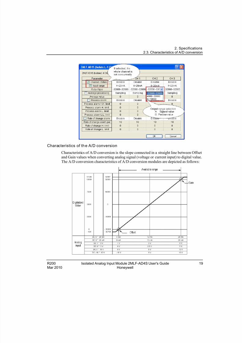
Characteristics of the A/D conversion
Characteristics of A/D conversion is the slope connected in a straight line between Offsetand Gain values when converting analog signal (voltage or current input) to digital value.
The A/D conversion characteristics of A/D conversion modules are depicted as follows:
R200 Isolated Analog Input Module 2MLF-AD4S User's Guide 19Mar 2010 Honeywell
8/22/2019 Analog Input Card R200
http://slidepdf.com/reader/full/analog-input-card-r200 20/80
2. Specifications2.3. Characteristics of A/D conversion
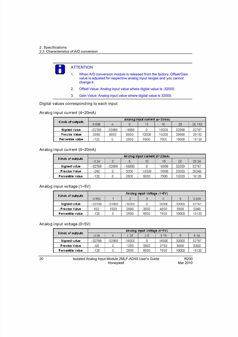
ATTENTION
1. When A/D conversion module is released from the factory, Offset/Gainvalue is adjusted for respective analog input ranges and you cannotchange it.
2. Offset Value: Analog input value where digital value is -32000.
3. Gain Value: Analog input value where digital value is 32000.
Digital values corresponding to each input
Analog input current (4~20mA)
Analog input current (0~20mA)
Analog input voltage (1~5V)
Analog input voltage (0~5V)
20 Isolated Analog Input Module 2MLF-AD4S User's Guide R200Honeywell Mar 2010
8/22/2019 Analog Input Card R200
http://slidepdf.com/reader/full/analog-input-card-r200 21/80
2. Specifications2.3. Characteristics of A/D conversion
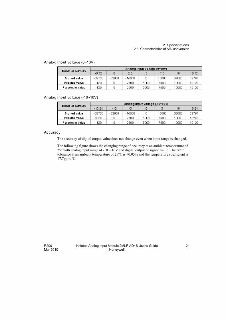
Analog input voltage (0~10V)
Analog input voltage (-10~10V)
Accuracy
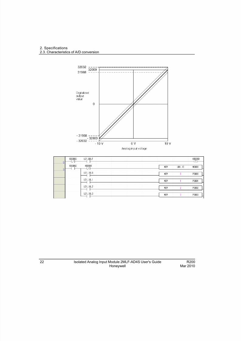
The accuracy of digital output value does not change even when input range is changed.
The following figure shows the changing range of accuracy at an ambient temperature of
25° with analog input range of -10 ~ 10V and digital output of signed value. The error
tolerance at an ambient temperature of 25°C is ±0.05% and the temperature coefficient is
17.7ppm/°C.
R200 Isolated Analog Input Module 2MLF-AD4S User's Guide 21Mar 2010 Honeywell
8/22/2019 Analog Input Card R200
http://slidepdf.com/reader/full/analog-input-card-r200 22/80
2. Specifications2.3. Characteristics of A/D conversion
22 Isolated Analog Input Module 2MLF-AD4S User's Guide R200Honeywell Mar 2010
8/22/2019 Analog Input Card R200
http://slidepdf.com/reader/full/analog-input-card-r200 23/80
R200 Isolated Analog Input Module 2MLF-AD4S User's Guide 23
3. Installation and Wiring
3.1 Wiring
Precautions for wiring
Observe the following precautions during wiring.
1. Do not keep AC power line near to A/D conversion module’s external input sign
line. By keeping enough distance, the line is free from surge or inductive noise.
2. Select a cable whose size is not less than the maximum cable standard of AWG22
(0.3mm
2
) by taking consideration of the ambient temperature and allowable current.3. Do not keep the cable too close to hot device and material or in direct contact with
oil for long. It causes damage or abnormal operation due to short circuit.
4. Check the polarity when wiring the terminal.
5. Wiring with high-voltage line or power line may produce inductive hindrance
causing abnormal operation or defect.
CAUTION I/O signal or communication line must be wired at least 100mm awayfrom the high-voltage cable or power line. If not, it may cause abnormaloutput or operation.
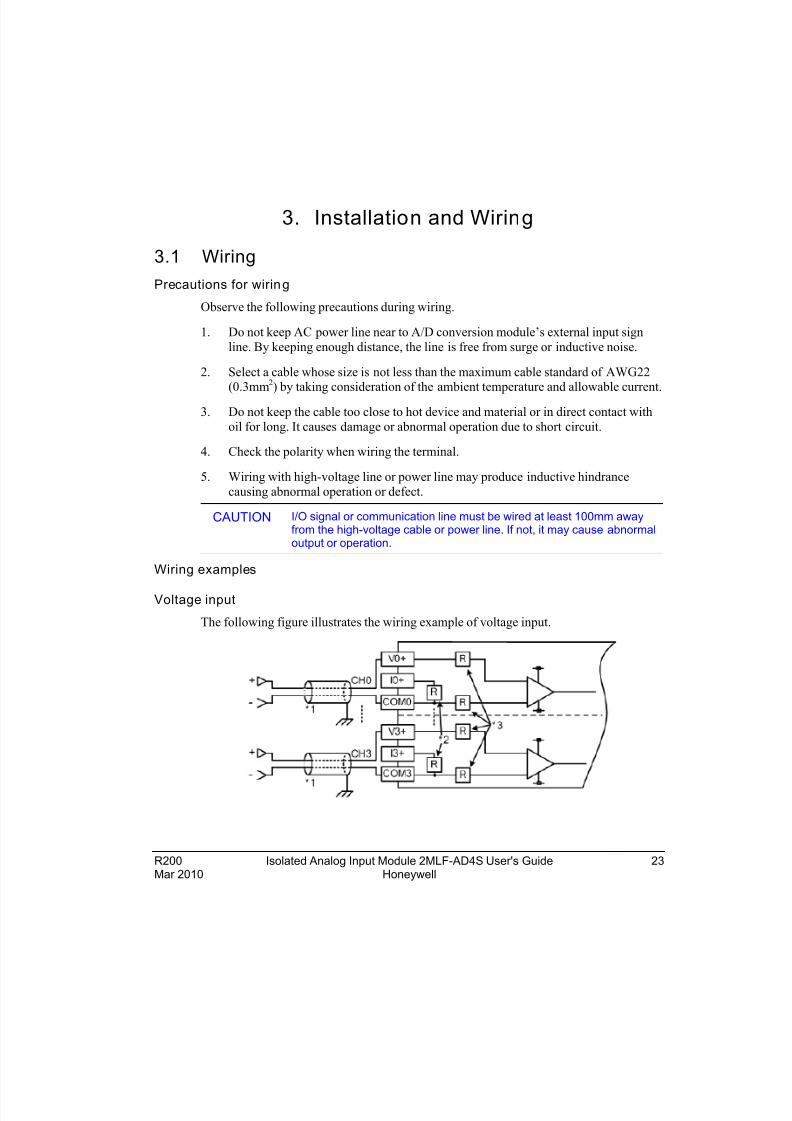
Wiring examples
Voltage input
The following figure illustrates the wiring example of voltage input.
Mar 2010 Honeywell
8/22/2019 Analog Input Card R200
http://slidepdf.com/reader/full/analog-input-card-r200 24/80
3. Installation and Wiring3.1. Wiring
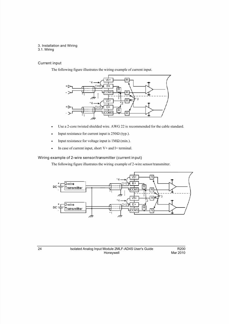
Current input
The following figure illustrates the wiring example of current input.
Use a 2-core twisted shielded wire. AWG 22 is recommended for the cable standard.
Input resistance for current input is 250Ω (typ.).
Input resistance for voltage input is 1MΩ (min.).
In case of current input, short V+ and I+ terminal.
Wiring example of 2-wire sensor/transmitter (current input)
The following figure illustrates the wiring example of 2-wire sensor/transmitter.
24 Isolated Analog Input Module 2MLF-AD4S User's Guide R200Honeywell Mar 2010
8/22/2019 Analog Input Card R200
http://slidepdf.com/reader/full/analog-input-card-r200 25/80
3. Installation and Wiring3.1. Wiring
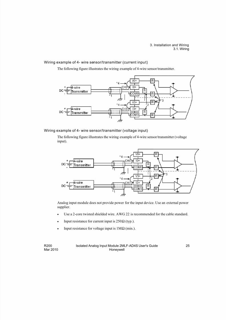
Wiring example of 4- wire sensor/transmitter (current input)
The following figure illustrates the wiring example of 4-wire sensor/transmitter.
Wiring example of 4- wire sensor/transmitter (voltage input)
The following figure illustrates the wiring example of 4-wire sensor/transmitter (voltage
input).
Analog input module does not provide power for the input device. Use an external power
supplier.
Use a 2-core twisted shielded wire. AWG 22 is recommended for the cable standard.
Input resistance for current input is 250Ω (typ.).
Input resistance for voltage input is 1MΩ (min.).
R200 Isolated Analog Input Module 2MLF-AD4S User's Guide 25Mar 2010 Honeywell
8/22/2019 Analog Input Card R200
http://slidepdf.com/reader/full/analog-input-card-r200 26/80
3. Installation and Wiring3.1. Wiring
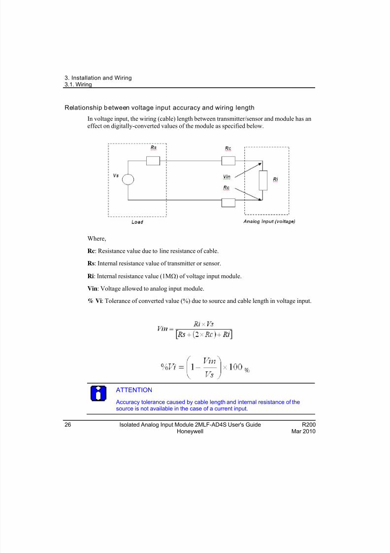
Relationship between voltage input accuracy and wiring length
In voltage input, the wiring (cable) length between transmitter/sensor and module has aneffect on digitally-converted values of the module as specified below.
Where,
Rc: Resistance value due to line resistance of cable.
Rs: Internal resistance value of transmitter or sensor.
Ri: Internal resistance value (1M) of voltage input module.
Vin: Voltage allowed to analog input module.
% Vi: Tolerance of converted value (%) due to source and cable length in voltage input.
ATTENTION
Accuracy tolerance caused by cable length and internal resistance of thesource is not available in the case of a current input.
26 Isolated Analog Input Module 2MLF-AD4S User's Guide R200Honeywell Mar 2010
8/22/2019 Analog Input Card R200
http://slidepdf.com/reader/full/analog-input-card-r200 27/80
3. Installation and Wiring3.1. Wiring
R200 Isolated Analog Input Module 2MLF-AD4S User's Guide 27Mar 2010 Honeywell
CAUTION Ensure correct wiring after checking the voltage rate of each
product and the arrangement of terminals. If not, it may cause fire,electric shock or abnormal operation.
Ensure to secure the screws of terminals tightly with specifiedtorque during wiring. If the screws of terminals get loose, it may causeshort circuit, fire or abnormal operation.
Ensure to use the ground wire of Class 3 for FG terminals, which isexclusively used for PLC. If the terminals are not groundedproperly, it may cause abnormal operation.
Do not allow any external materials such as wiring waste inside the
module while wiring, for it may cause fire, damage on the productor abnormal operation.
8/22/2019 Analog Input Card R200
http://slidepdf.com/reader/full/analog-input-card-r200 28/80
3. Installation and Wiring3.2. Installation
28 Isolated Analog Input Module 2MLF-AD4S User's Guide R200Honeywell Mar 2010
3.2 Installation
Installation environment
The isolated analog input module is designed to withstand extreme climatic conditions.However, care must be taken for the following items to ensure reliability and stability.
Environmental conditions
Install on a waterproof and dustproof control panel.
Ensure that there is no continuous impact or vibration on the module.
Avoid exposure to direct sunlight.
Ensure that there is no dew formation caused by rapid change in temperature.
Ensure an ambient temperature of 0-55°.
Installation
Ensure that wiring waste does not accumulate inside the PLC during wiring or drilling screw holes.
Do not install on the same panel as a high-voltage device.
Ensure a distance of at least 50mm from a duct or near-by module.
Ensure that the module is grounded in a noiseless place.
CAUTION Use PLC only in the environment specified in this guide or general
standard of data sheet. If not, it may cause an electric shock, fire,or abnormal operation of the product or flames.
Before installing the module, ensure PLC power is off. If not, it maycause an electric shock or damage on the product.
Ensure that each module of PLC is correctly secured. If not, it maycause an abnormal operation, error or dropping.
Ensure that I/O or extension connector is correctly secured. If not, itmay cause an electric shock, fire or abnormal operation.
If a lot of vibration is expected in the installation environment, do
not let PLC directly to vibrate. It may cause an electric shock, fire or abnormal operation.
Do not keep any external metallic materials inside the product; itmay cause an electric shock, fire or abnormal operation.
8/22/2019 Analog Input Card R200
http://slidepdf.com/reader/full/analog-input-card-r200 29/80
3. Installation and Wiring3.2. Installation
Precautions for handling
Precautions for handling isolated A/D conversion module from the installation are asfollows:
1. Ensure that the module is not dropped and subjected to shock.
2. Do not remove PCB from the case. It may cause abnormal operation.
3. Ensure that no external materials including wiring waste gets inside the modulewhen wiring. Remove external materials if any inside.
4. Do not install or remove the module when power is ON.
WARNING
Do not touch the terminal when powered. It may cause an electric shockor abnormal operation.
Prior to cleaning or tightening the terminal screws, let all the externalpower off including PLC power. If not, it may cause an electric shock or abnormal operation.
Do not let the battery recharge, disassemble, heat, short or solder. Heat,
explosion or ignition may cause injuries or fire.
R200 Isolated Analog Input Module 2MLF-AD4S User's Guide 29Mar 2010 Honeywell

8/22/2019 Analog Input Card R200
http://slidepdf.com/reader/full/analog-input-card-r200 30/80
3. Installation and Wiring3.2. Installation
30 Isolated Analog Input Module 2MLF-AD4S User's Guide R200Honeywell Mar 2010
8/22/2019 Analog Input Card R200
http://slidepdf.com/reader/full/analog-input-card-r200 31/80
R200 Isolated Analog Input Module 2MLF-AD4S User's Guide 31Mar 2010 Honeywell
4. Configuration
4.1 Configuration of analog input module
Functions of A/D conversion
The following table describes the function of A/D conversion module.
Function Item Details
Enables the channelsEnables the specified channels to execute A/Dconversion.
Select the range of input Four types of voltage inputs and two types of currentinputs are available for the 2MLF-AD4S module.
Select the output dataThree kinds of output data formats are provided in thismodule. (signed, precise and percentile value)
A/D conversion methods
Sampling processing
Sample processing is performed when the averageprocessing is not specified.
a) Average processing
b) Time average processing
c) Count average processing
d) Moving average processing
e) Weighted average processing
Alarm processing Process alarm and change rate alarm processing areavailable.
Detecting the disconnectionof input signal
If an analog input with a range of 1 ~ 5V (4 ~ 20°) isdisconnected, the user program detects it.
Sampling processing
The sampling period (processing time) depends on the number of the channels in use.
Processing time = Maximum of 10ms per module
8/22/2019 Analog Input Card R200
http://slidepdf.com/reader/full/analog-input-card-r200 32/80
4. Configuration4.1. Configuration of analog input module
Average processing
This processing executes A/D conversion with specified count/time and to save theaverage of the accumulated sum on memory. Average processing option and time/count
value can be defined through a user program or I/O parameters setting for respective
channels.
This process reduces the influence of abnormal analog input signals such as noise.
Types of average processing
There are four types of average processing: time, count, moving and weighted average.
1. Time average processing
a) Setting range: 16 ~ 4000 (ms)
b) Number of processing= [setting time/10ms][time]
Example: Setting time: 68ms
Number of processing = 68ms / 10ms = 6.86[times] (rounded)
ATTENTION
1. If set value of time average is not specified within 16 ~ 4000, RUN LEDblinks at an interval of 1s. In order to set RUN LED to on state, set thevalue within the range again and then change the PLC CPU from STOPto RUN mode. Ensure to use request flag of error clear (UXY.11.0) to
clear the error during RUN.
2. If any error occurs in set value of time average, the default value is setas 16.
2. Count average processing
a) Setting range: 2 ~ 500 (times)
The average value of input data at designated times is saved as a real input data.
b) Process time = setting count x 10ms
Example: Average processing time is 50
Processing time = 50*10ms => 500ms
32 Isolated Analog Input Module 2MLF-AD4S User's Guide R200Honeywell Mar 2010
8/22/2019 Analog Input Card R200
http://slidepdf.com/reader/full/analog-input-card-r200 33/80
4. Configuration4.1. Configuration of analog input module
ATTENTION
1. If the set value of count average is not specified within 2 ~ 500, RUNLED blinks at an interval of 1s. In order to set RUN LED to ON state, setthe value within the range and then change PLC CPU from STOP toRUN mode. Ensure to use request flag of error clear (UXY.11.0) to clear the error during RUN.
2. If any error occurs in the set value, the default value is set as 2.
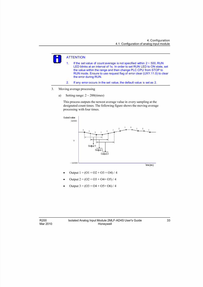
3. Moving average processing
a) Setting range: 2 ~ 200(times)
This process outputs the newest average value in every sampling at thedesignated count times. The following figure shows the moving average
processing with four times.
Output 1 = (O1 + O2 + O3 + O4) / 4
Output 2 = (O2 + O3 + O4+ O5) / 4
Output 3 = (O3 + O4 + O5+ O6) / 4
R200 Isolated Analog Input Module 2MLF-AD4S User's Guide 33Mar 2010 Honeywell
8/22/2019 Analog Input Card R200
http://slidepdf.com/reader/full/analog-input-card-r200 34/80
4. Configuration4.1. Configuration of analog input module
4. Weighted average processing
a) Setting range: 1 ~ 99(%)
F[n] = (1 - α) x A[n] + α x F [n - 1]
F[n]: Current weighted average output
[n]: Current A/D conversion value
F [n-1]: Former weighted average output
α: Weighted average constant (0.01 ~ 0.99)
ATTENTION
If the set value of count average is not specified within 1 ~ 99, RUN LEDblinks at an interval of 1s. In order to set RUN LED to ON status, reset theset value of frequency average within 2 ~ 500 and then convert PLC CPUfrom STOP to RUN. Be sure to use request flag of error clear (UXY.11.0)to clear the error through modification during RUN.
If any error occurs in the set value, the default value is set as 1.
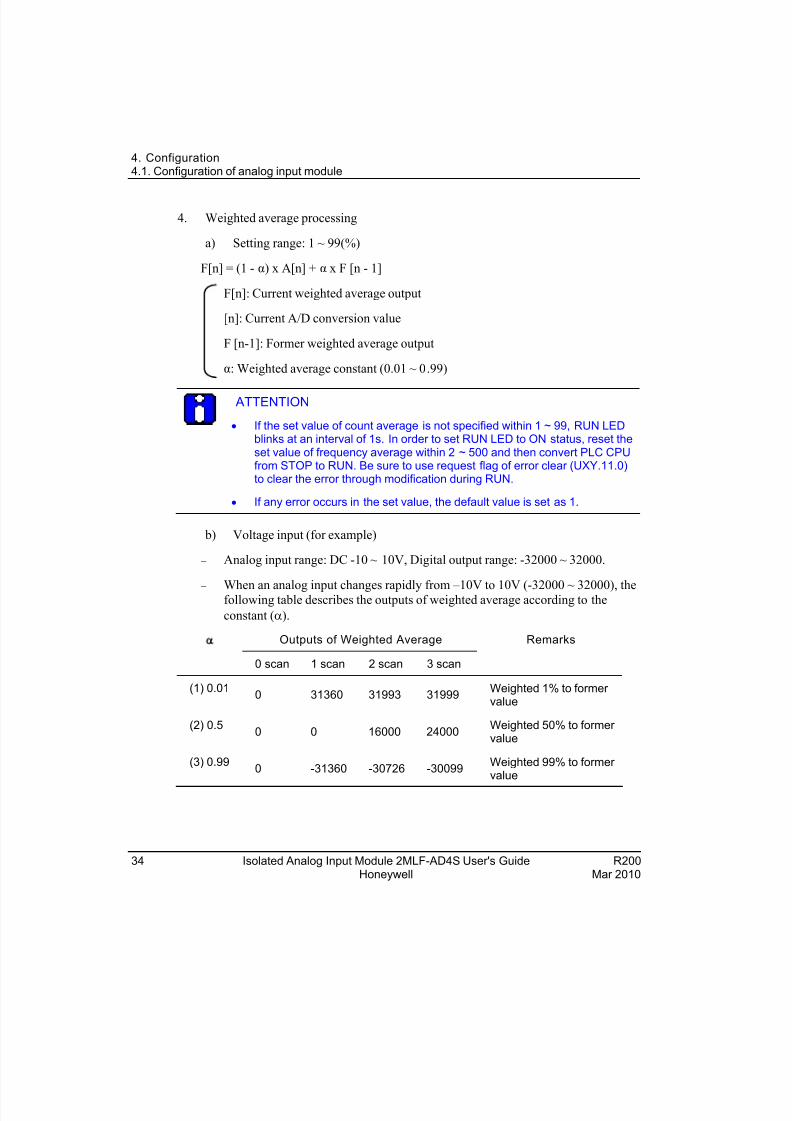
b) Voltage input (for example)
Analog input range: DC -10 ~ 10V, Digital output range: -32000 ~ 32000.
When an analog input changes rapidly from –10V to 10V (-32000 ~ 32000), thefollowing table describes the outputs of weighted average according to the
constant ().
Outputs of Weighted Average
0 scan 1 scan 2 scan 3 scan
Remarks
(1) 0.010 31360 31993 31999
Weighted 1% to former value
(2) 0.50 0 16000 24000
Weighted 50% to former value
(3) 0.990 -31360 -30726 -30099
Weighted 99% to former value
34 Isolated Analog Input Module 2MLF-AD4S User's Guide R200Honeywell Mar 2010
8/22/2019 Analog Input Card R200
http://slidepdf.com/reader/full/analog-input-card-r200 35/80
4. Configuration4.1. Configuration of analog input module
R200 Isolated Analog Input Module 2MLF-AD4S User's Guide 35Mar 2010 Honeywell
(1) Outputs 32000 after about 4 scans
(2) Outputs 32000 after about 24 scans
(3) Outputs 32000 after about 1629 scans (16.29s)
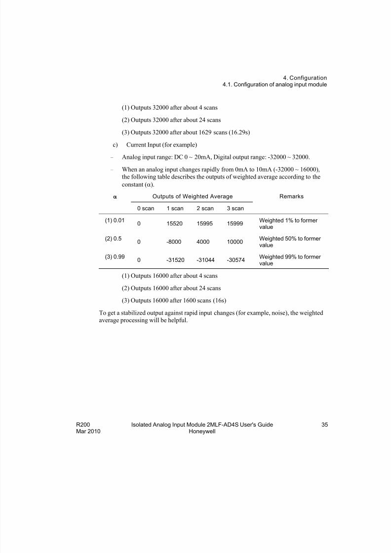
c) Current Input (for example)
Analog input range: DC 0 ~ 20mA, Digital output range: -32000 ~ 32000.
When an analog input changes rapidly from 0mA to 10mA (-32000 ~ 16000),
the following table describes the outputs of weighted average according to the
constant ().
Outputs of Weighted Average
0 scan 1 scan 2 scan 3 scan
Remarks
(1) 0.010 15520 15995 15999
Weighted 1% to former value
(2) 0.50 -8000 4000 10000
Weighted 50% to former value
(3) 0.990 -31520 -31044 -30574
Weighted 99% to former value
(1) Outputs 16000 after about 4 scans
(2) Outputs 16000 after about 24 scans
(3) Outputs 16000 after 1600 scans (16s)
To get a stabilized output against rapid input changes (for example, noise), the weighted
average processing will be helpful.
8/22/2019 Analog Input Card R200
http://slidepdf.com/reader/full/analog-input-card-r200 36/80
4. Configuration4.1. Configuration of analog input module
36 Isolated Analog Input Module 2MLF-AD4S User's Guide R200Honeywell Mar 2010
Alarm processing
Process alarm
When the input value becomes greater than process alarm HH limit value, or less than LL
limit value, the alarm flag turns on and the alarm LED on the front of the module
flickers. When the input value becomes less than process alarm H limit value, or greater than L limit value, the alarms are cleared.
Change rate alarm
This function enables to sample data cyclically with the period set in the parameter rate
of change alarm period and to compare every two sample data.
The unit used for rate of change H limit and rate of change L limit is percentage per second (%/s).
1. Setting rate of the sampling period: 10 ~ 5000(ms)
If 1000 is set for the period, the input data is sampled and compared every 1second.
2. Setting range of change rate limit: -32768 ~ 32767(-3276.8%/s ~ 3276.7%/s)
3. Calculation of the criterion
The criterion of change rate alarm = High limit or low limit of change rate alarm X0.001 X 64000 X Detection period ÷ 1000
Example for change rate setting 1(rising rate detection)
1. Detection period of Ch. 0: 10(ms)
2. Alarm high (H) limit of Ch. 0: 100(10.0%)
3. Alarm low (L) limit of Ch. 0: 90(9.0%)
4. Alarm high(H) criterion of Ch.0 = 100 X 0.001 X 64000 X 10 ÷ 1000 = 64
5. Alarm low(L) criterion of Ch.0= 90 X 0.001 X 64000 X 10 ÷ 1000 = 57.6 = 57
6. When the deviation value of ([n]th digital value) – ([n-1] th digital value) becomes
greater than 64, high (H) change rate detection flag of Ch.0 (CH0 H) turns on.
7. When the deviation value of ([n] th digital value) – ([n-1] th digital value) becomes
less than 57, low (L) change rate detection flag of Ch.0 (CH0 L) turns on.
8/22/2019 Analog Input Card R200
http://slidepdf.com/reader/full/analog-input-card-r200 37/80
4. Configuration4.1. Configuration of analog input module
R200 Isolated Analog Input Module 2MLF-AD4S User's Guide 37Mar 2010 Honeywell
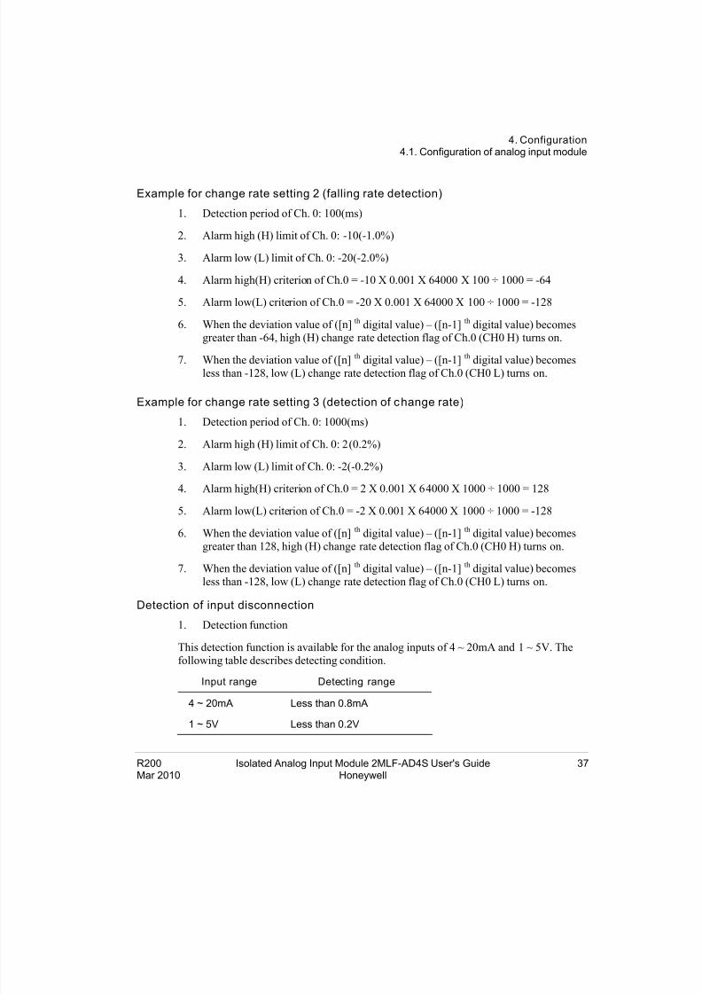
Example for change rate setting 2 (falling rate detection)
1. Detection period of Ch. 0: 100(ms)
2. Alarm high (H) limit of Ch. 0: -10(-1.0%)
3. Alarm low (L) limit of Ch. 0: -20(-2.0%)
4. Alarm high(H) criterion of Ch.0 = -10 X 0.001 X 64000 X 100 ÷ 1000 = -64
5. Alarm low(L) criterion of Ch.0 = -20 X 0.001 X 64000 X 100 ÷ 1000 = -128
6. When the deviation value of ([n] th digital value) – ([n-1] th digital value) becomesgreater than -64, high (H) change rate detection flag of Ch.0 (CH0 H) turns on.
7. When the deviation value of ([n] th digital value) – ([n-1] th digital value) becomes
less than -128, low (L) change rate detection flag of Ch.0 (CH0 L) turns on.
Example for change rate setting 3 (detection of change rate)
1. Detection period of Ch. 0: 1000(ms)
2. Alarm high (H) limit of Ch. 0: 2(0.2%)
3. Alarm low (L) limit of Ch. 0: -2(-0.2%)
4. Alarm high(H) criterion of Ch.0 = 2 X 0.001 X 64000 X 1000 ÷ 1000 = 128
5. Alarm low(L) criterion of Ch.0 = -2 X 0.001 X 64000 X 1000 ÷ 1000 = -128
6. When the deviation value of ([n] th digital value) – ([n-1] th digital value) becomes
greater than 128, high (H) change rate detection flag of Ch.0 (CH0 H) turns on.
7. When the deviation value of ([n] th digital value) – ([n-1] th digital value) becomes
less than -128, low (L) change rate detection flag of Ch.0 (CH0 L) turns on.
Detection of input disconnection
1. Detection function
This detection function is available for the analog inputs of 4 ~ 20mA and 1 ~ 5V. The
following table describes detecting condition.
Input range Detecting range
4 ~ 20mA Less than 0.8mA
1 ~ 5V Less than 0.2V
8/22/2019 Analog Input Card R200
http://slidepdf.com/reader/full/analog-input-card-r200 38/80
4. Configuration4.1. Configuration of analog input module
38 Isolated Analog Input Module 2MLF-AD4S User's Guide R200Honeywell Mar 2010
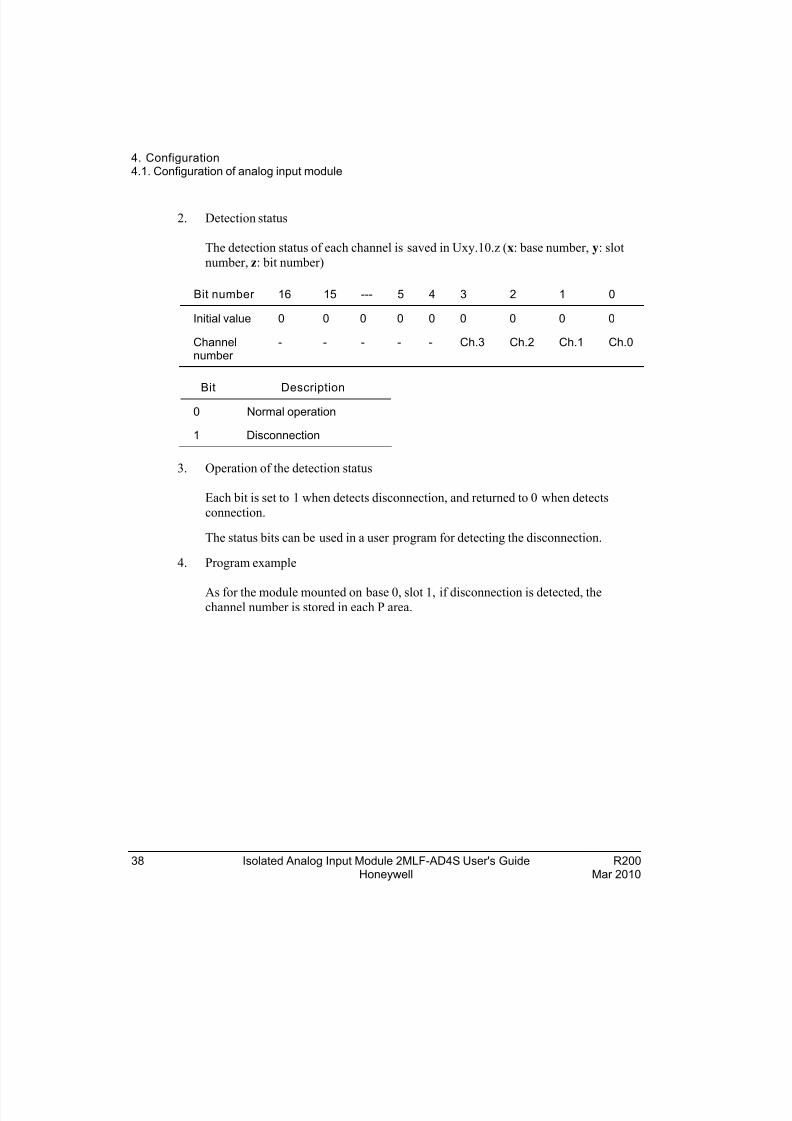
2. Detection status
The detection status of each channel is saved in Uxy.10.z (x: base number, y: slot
number, z: bit number)
Bit number 16 15 --- 5 4 3 2 1 0
Initial value 0 0 0 0 0 0 0 0 0
Channelnumber
- - - - - Ch.3 Ch.2 Ch.1 Ch.0
Bit Description
0 Normal operation
1 Disconnection
3. Operation of the detection status
Each bit is set to 1 when detects disconnection, and returned to 0 when detects
connection.
The status bits can be used in a user program for detecting the disconnection.
4. Program example
As for the module mounted on base 0, slot 1, if disconnection is detected, thechannel number is stored in each P area.
8/22/2019 Analog Input Card R200
http://slidepdf.com/reader/full/analog-input-card-r200 39/80
4. Configuration4.2. Internal memory configuration
R200 Isolated Analog Input Module 2MLF-AD4S User's Guide 39Mar 2010 Honeywell
4.2 Internal memory conf iguration
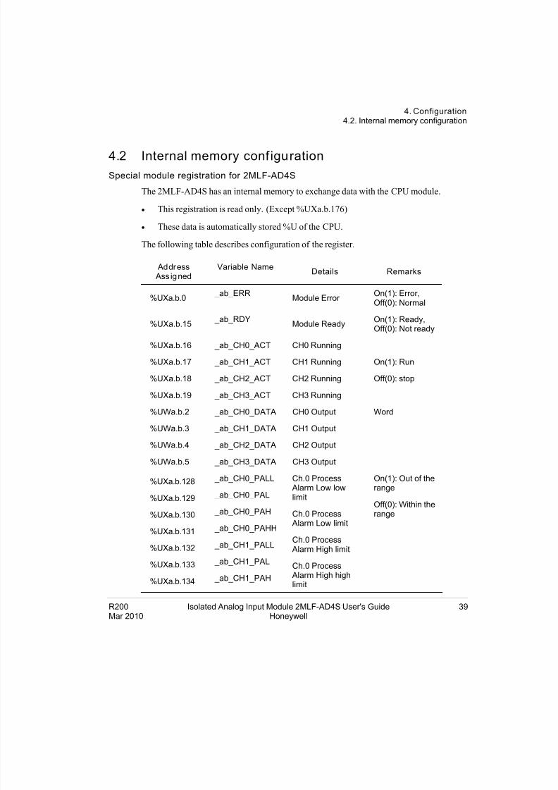
Special module registration for 2MLF-AD4S
The 2MLF-AD4S has an internal memory to exchange data with the CPU module.
This registration is read only. (Except %UXa.b.176)
These data is automatically stored %U of the CPU.
The following table describes configuration of the register.
Address
Ass igned
Variable NameDetails Remarks
%UXa.b.0 _ab_ERR
Module Error On(1): Error,Off(0): Normal
%UXa.b.15 _ab_RDY
Module ReadyOn(1): Ready,Off(0): Not ready
%UXa.b.16
%UXa.b.17
%UXa.b.18
%UXa.b.19
_ab_CH0_ACT
_ab_CH1_ACT
_ab_CH2_ACT
_ab_CH3_ACT
CH0 Running
CH1 Running
CH2 Running
CH3 Running
On(1): Run
Off(0): stop
%UWa.b.2 _ab_CH0_DATA CH0 Output
%UWa.b.3 _ab_CH1_DATA CH1 Output
%UWa.b.4 _ab_CH2_DATA CH2 Output
%UWa.b.5 _ab_CH3_DATA CH3 Output
Word
%UXa.b.128
%UXa.b.129
%UXa.b.130
%UXa.b.131
%UXa.b.132
%UXa.b.133
%UXa.b.134
_ab_CH0_PALL
_ab_CH0_PAL
_ab_CH0_PAH
_ab_CH0_PAHH
_ab_CH1_PALL
_ab_CH1_PAL
_ab_CH1_PAH
Ch.0 Process Alarm Low lowlimit
Ch.0 Process Alarm Low limit
Ch.0 Process Alarm High limit
Ch.0 Process Alarm High highlimit
On(1): Out of therange
Off(0): Within therange
8/22/2019 Analog Input Card R200
http://slidepdf.com/reader/full/analog-input-card-r200 40/80
4. Configuration4.2. Internal memory configuration
40 Isolated Analog Input Module 2MLF-AD4S User's Guide R200Honeywell Mar 2010
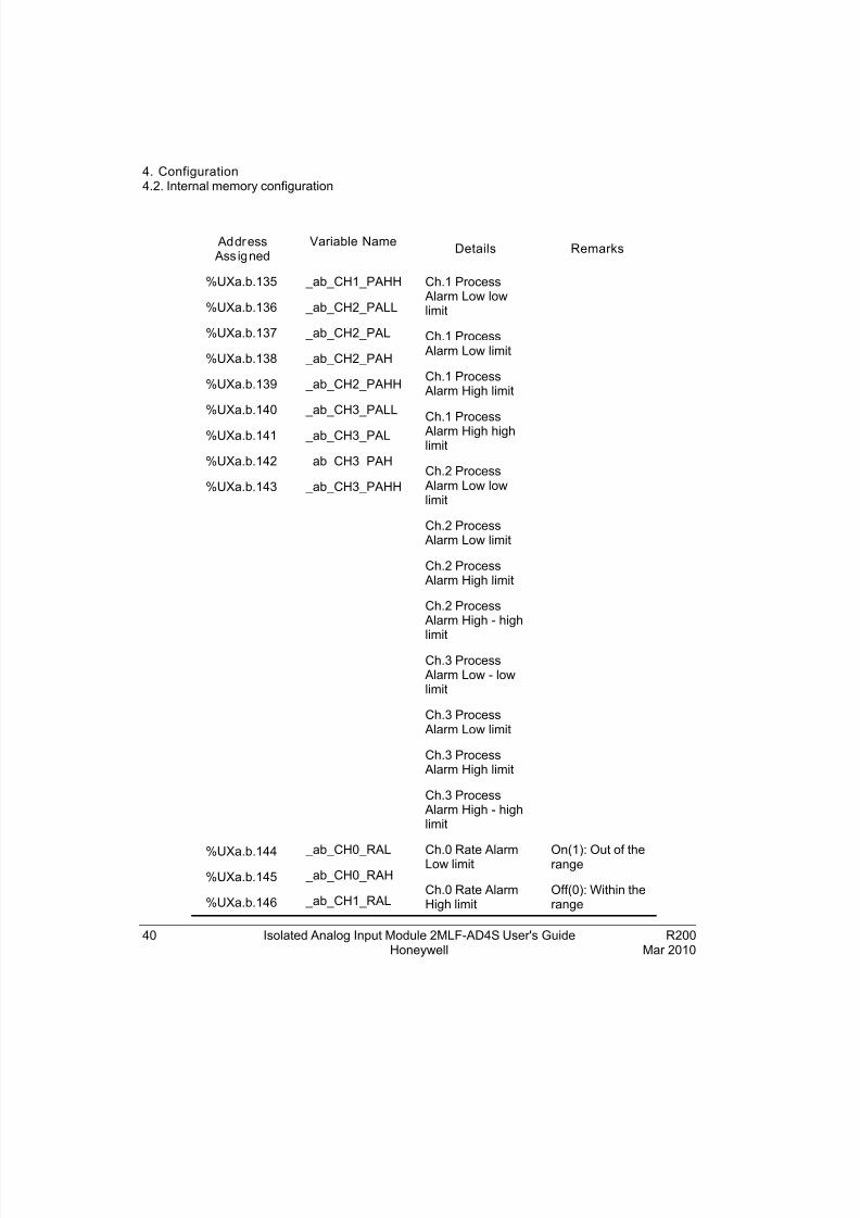
Address Ass igned
Variable NameDetails Remarks
%UXa.b.135
%UXa.b.136
%UXa.b.137
%UXa.b.138
%UXa.b.139
%UXa.b.140
%UXa.b.141
%UXa.b.142
%UXa.b.143
_ab_CH1_PAHH
_ab_CH2_PALL
_ab_CH2_PAL
_ab_CH2_PAH
_ab_CH2_PAHH
_ab_CH3_PALL
_ab_CH3_PAL
_ab_CH3_PAH
_ab_CH3_PAHH
Ch.1 Process Alarm Low lowlimit
Ch.1 Process Alarm Low limit
Ch.1 Process Alarm High limit
Ch.1 Process
Alarm High highlimit
Ch.2 Process Alarm Low lowlimit
Ch.2 Process Alarm Low limit
Ch.2 Process Alarm High limit
Ch.2 Process Alarm High - high
limit
Ch.3 Process Alarm Low - lowlimit
Ch.3 Process Alarm Low limit
Ch.3 Process Alarm High limit
Ch.3 Process Alarm High - highlimit
%UXa.b.144
%UXa.b.145
%UXa.b.146
_ab_CH0_RAL
_ab_CH0_RAH
_ab_CH1_RAL
Ch.0 Rate AlarmLow limit
Ch.0 Rate AlarmHigh limit
On(1): Out of therange
Off(0): Within therange
8/22/2019 Analog Input Card R200
http://slidepdf.com/reader/full/analog-input-card-r200 41/80
4. Configuration4.2. Internal memory configuration
R200 Isolated Analog Input Module 2MLF-AD4S User's Guide 41Mar 2010 Honeywell
Address Ass igned
Variable NameDetails Remarks
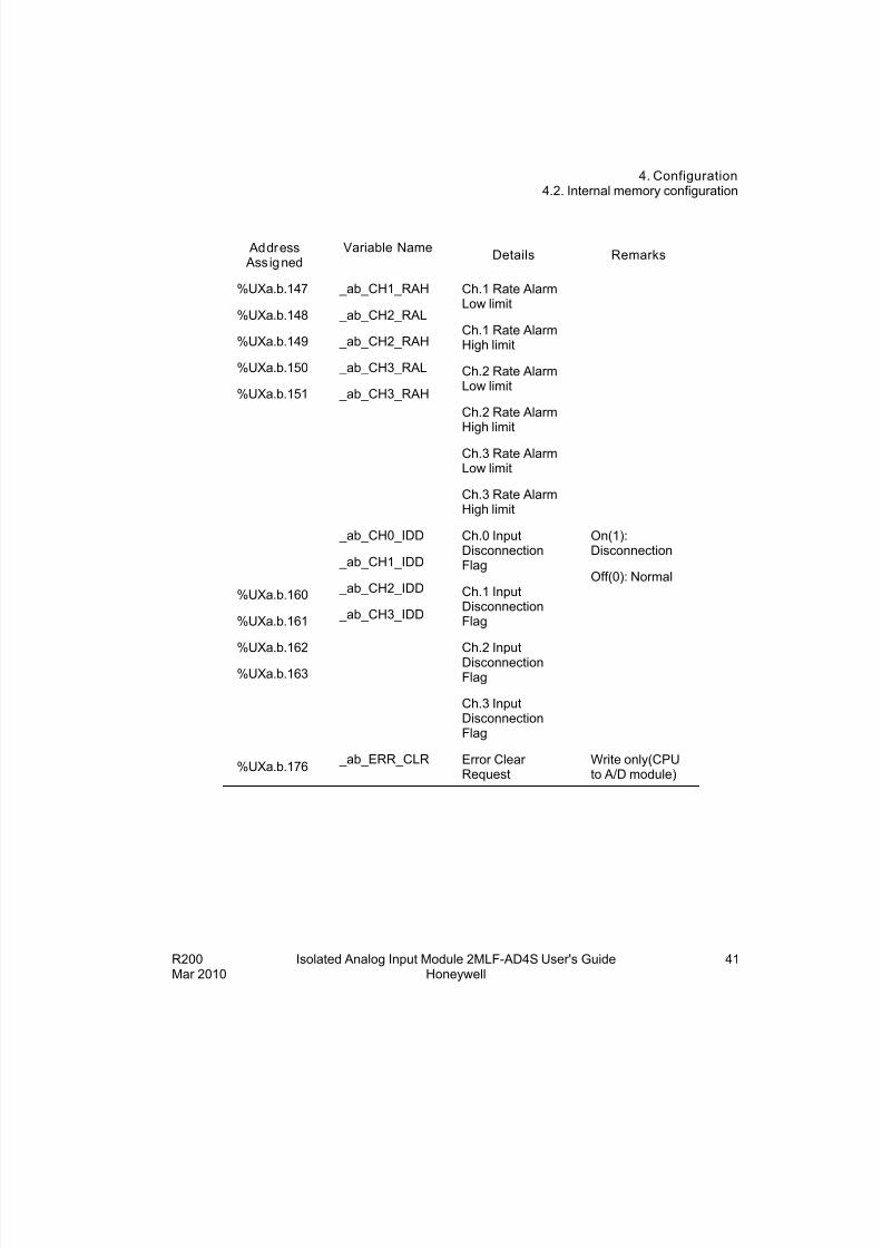
%UXa.b.147
%UXa.b.148
%UXa.b.149
%UXa.b.150
%UXa.b.151
_ab_CH1_RAH
_ab_CH2_RAL
_ab_CH2_RAH
_ab_CH3_RAL
_ab_CH3_RAH
Ch.1 Rate AlarmLow limit
Ch.1 Rate AlarmHigh limit
Ch.2 Rate AlarmLow limit
Ch.2 Rate AlarmHigh limit
Ch.3 Rate AlarmLow limit
Ch.3 Rate AlarmHigh limit
%UXa.b.160
%UXa.b.161
%UXa.b.162
%UXa.b.163
_ab_CH0_IDD
_ab_CH1_IDD
_ab_CH2_IDD
_ab_CH3_IDD
Ch.0 InputDisconnectionFlag
Ch.1 InputDisconnectionFlag
Ch.2 InputDisconnectionFlag
Ch.3 InputDisconnectionFlag
On(1):Disconnection
Off(0): Normal
%UXa.b.176 _ab_ERR_CLR Error Clear
RequestWrite only(CPUto A/D module)
8/22/2019 Analog Input Card R200
http://slidepdf.com/reader/full/analog-input-card-r200 42/80
4. Configuration4.2. Internal memory configuration
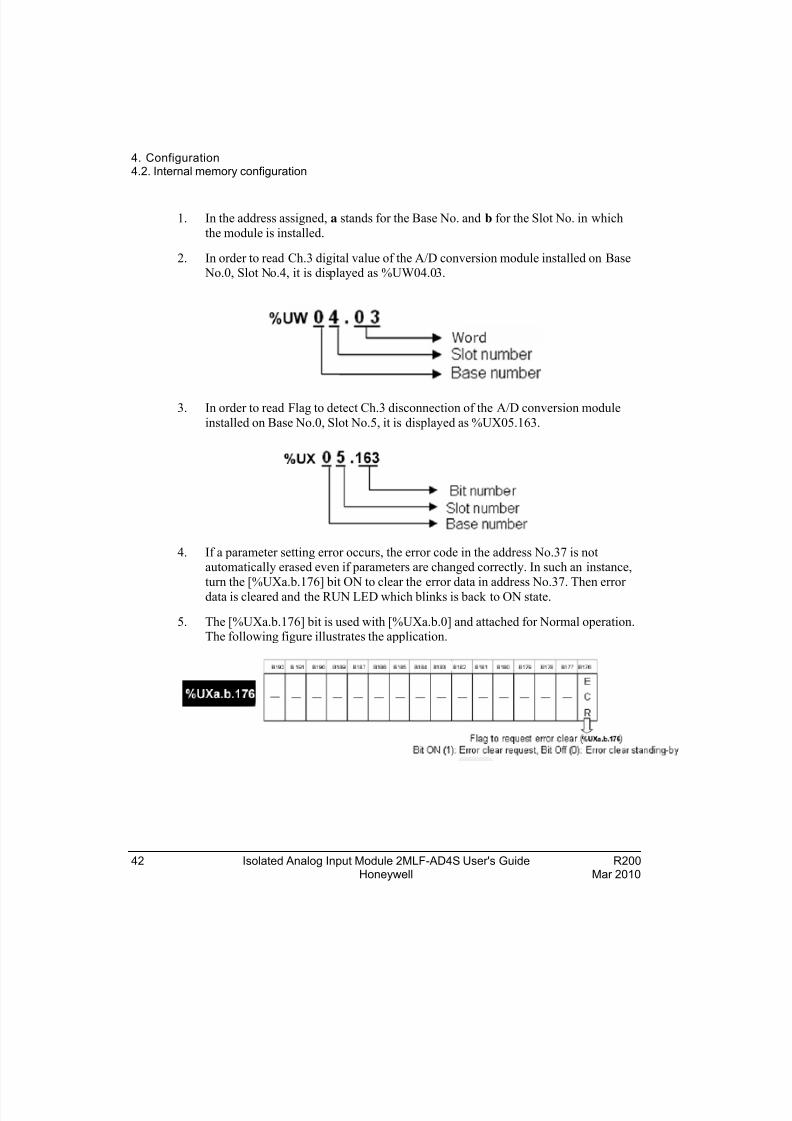
1. In the address assigned, a stands for the Base No. and b for the Slot No. in which
the module is installed.
2. In order to read Ch.3 digital value of the A/D conversion module installed on Base No.0, Slot No.4, it is displayed as %UW04.03.
3. In order to read Flag to detect Ch.3 disconnection of the A/D conversion module
installed on Base No.0, Slot No.5, it is displayed as %UX05.163.
4. If a parameter setting error occurs, the error code in the address No.37 is notautomatically erased even if parameters are changed correctly. In such an instance,
turn the [%UXa.b.176] bit ON to clear the error data in address No.37. Then error
data is cleared and the RUN LED which blinks is back to ON state.
5. The [%UXa.b.176] bit is used with [%UXa.b.0] and attached for Normal operation.The following figure illustrates the application.
42 Isolated Analog Input Module 2MLF-AD4S User's Guide R200Honeywell Mar 2010
8/22/2019 Analog Input Card R200
http://slidepdf.com/reader/full/analog-input-card-r200 43/80
4. Configuration4.2. Internal memory configuration
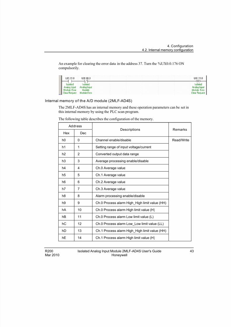
An example for clearing the error data in the address 37. Turn the %UX0.0.176 ON
compulsorily.
Internal memory of the A/D module (2MLF-AD4S)
The 2MLF-AD4S has an internal memory and these operation parameters can be set in
this internal memory by using the PLC scan program.
The following table describes the configuration of the memory.
Address
Hex DecDescriptions Remarks
h0 0 Channel enable/disable
h1 1 Setting range of input voltage/current
h2 2 Converted output data range
h3 3 Average processing enable/disable
h4 4 Ch.0 Average value
h5 5 Ch.1 Average value
h6 6 Ch.2 Average value
h7 7 Ch.3 Average value
h8 8 Alarm processing enable/disable
h9 9 Ch.0 Process alarm High_High limit value (HH)
hA 10 Ch.0 Process alarm High limit value (H)
hB 11 Ch.0 Process alarm Low limit value (L)
hC 12 Ch.0 Process alarm Low_Low limit value (LL)
hD 13 Ch.1 Process alarm High_High limit value (HH)
hE 14 Ch.1 Process alarm High limit value (H)
Read/Write
R200 Isolated Analog Input Module 2MLF-AD4S User's Guide 43Mar 2010 Honeywell
8/22/2019 Analog Input Card R200
http://slidepdf.com/reader/full/analog-input-card-r200 44/80
4. Configuration4.2. Internal memory configuration
44 Isolated Analog Input Module 2MLF-AD4S User's Guide R200Honeywell Mar 2010
Address
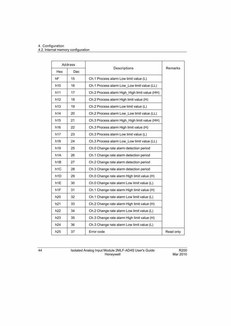
Hex DecDescriptions Remarks
hF 15 Ch.1 Process alarm Low limit value (L)
h10 16 Ch.1 Process alarm Low_Low limit value (LL)
h11 17 Ch.2 Process alarm High_High limit value (HH)
h12 18 Ch.2 Process alarm High limit value (H)
h13 19 Ch.2 Process alarm Low limit value (L)
h14 20 Ch.2 Process alarm Low_Low limit value (LL)
h15 21 Ch.3 Process alarm High_High limit value (HH)
h16 22 Ch.3 Process alarm High limit value (H)
h17 23 Ch.3 Process alarm Low limit value (L)
h18 24 Ch.3 Process alarm Low_Low limit value (LL)
h19 25 Ch.0 Change rate alarm detection period
h1A 26 Ch.1 Change rate alarm detection period
h1B 27 Ch.2 Change rate alarm detection period
h1C 28 Ch.3 Change rate alarm detection period
h1D 29 Ch.0 Change rate alarm High limit value (H)
h1E 30 Ch.0 Change rate alarm Low limit value (L)
h1F 31 Ch.1 Change rate alarm High limit value (H)
h20 32 Ch.1 Change rate alarm Low limit value (L)
h21 33 Ch.2 Change rate alarm High limit value (H)
h22 34 Ch.2 Change rate alarm Low limit value (L)
h23 35 Ch.3 Change rate alarm High limit value (H)
h24 36 Ch.3 Change rate alarm Low limit value (L)
h25 37 Error code Read only
8/22/2019 Analog Input Card R200
http://slidepdf.com/reader/full/analog-input-card-r200 45/80
4. Configuration4.2. Internal memory configuration
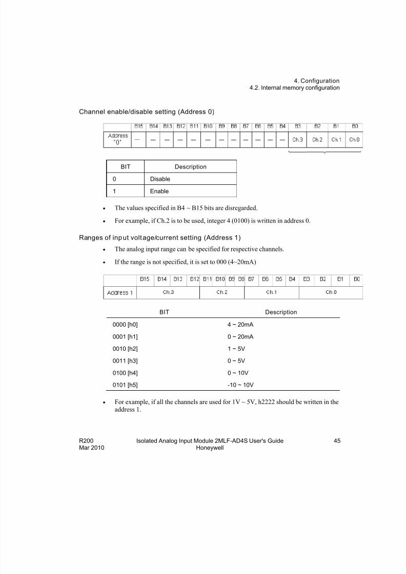
Channel enable/disable setting (Address 0)
BIT Description
0 Disable
1 Enable
The values specified in B4 ~ B15 bits are disregarded.
For example, if Ch.2 is to be used, integer 4 (0100) is written in address 0.
Ranges of input voltage/current setting (Address 1)
The analog input range can be specified for respective channels.
If the range is not specified, it is set to 000 (4~20mA)
BIT Description
0000 [h0] 4 ~ 20mA
0001 [h1] 0 ~ 20mA
0010 [h2] 1 ~ 5V
0011 [h3] 0 ~ 5V
0100 [h4] 0 ~ 10V
0101 [h5] -10 ~ 10V
For example, if all the channels are used for 1V ~ 5V, h2222 should be written in theaddress 1.
R200 Isolated Analog Input Module 2MLF-AD4S User's Guide 45Mar 2010 Honeywell
8/22/2019 Analog Input Card R200
http://slidepdf.com/reader/full/analog-input-card-r200 46/80
4. Configuration4.2. Internal memory configuration
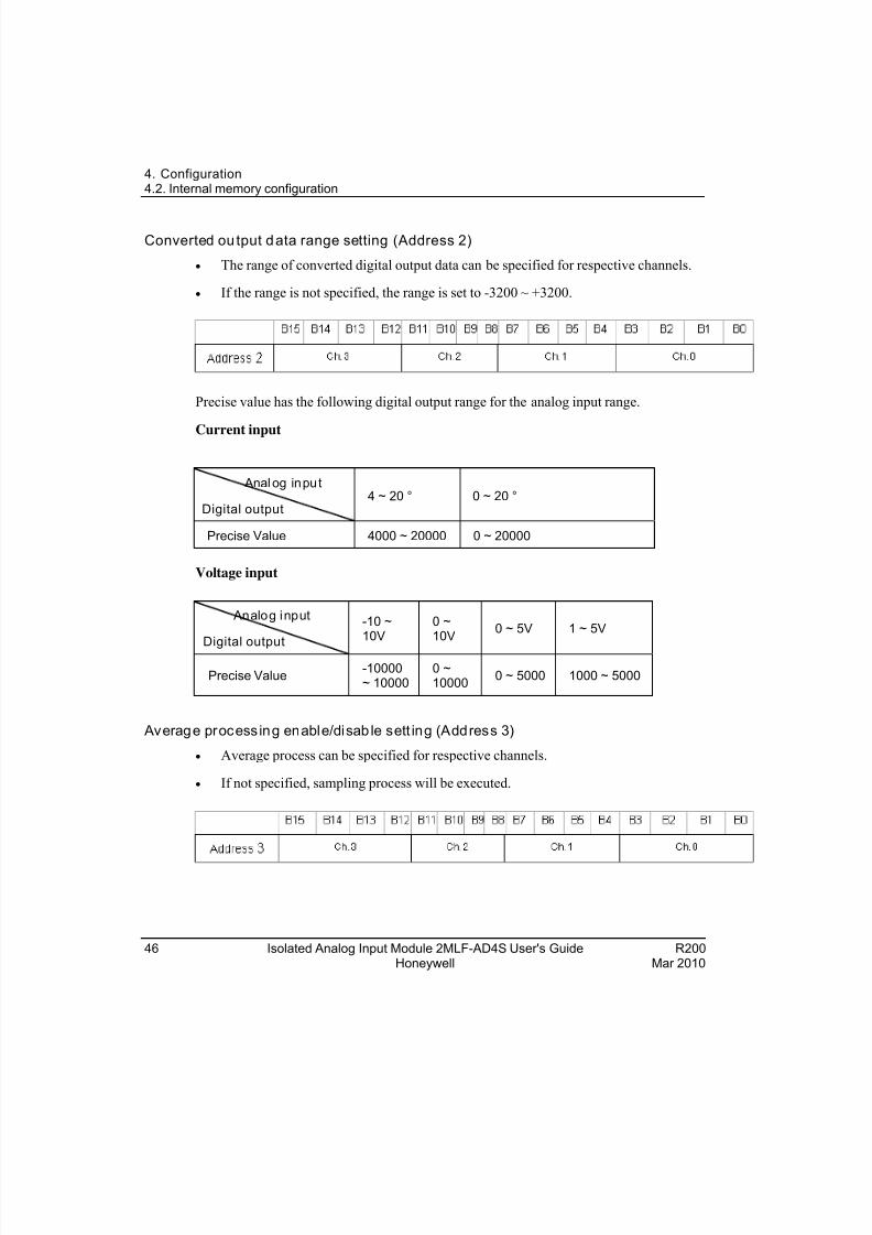
Converted output data range setting (Address 2)
The range of converted digital output data can be specified for respective channels.
If the range is not specified, the range is set to -3200 ~ +3200.
Precise value has the following digital output range for the analog input range.
Current input
Analog input
Digital output4 ~ 20 ° 0 ~ 20 °
Precise Value 4000 ~ 20000 0 ~ 20000
Voltage input
Analog input
Digital output
-10 ~10V
0 ~10V
0 ~ 5V 1 ~ 5V
Precise Value-10000~ 10000
0 ~10000
0 ~ 5000 1000 ~ 5000
Average processing enable/disab le sett ing (Address 3)
Average process can be specified for respective channels.
If not specified, sampling process will be executed.
46 Isolated Analog Input Module 2MLF-AD4S User's Guide R200Honeywell Mar 2010
8/22/2019 Analog Input Card R200
http://slidepdf.com/reader/full/analog-input-card-r200 47/80
4. Configuration4.2. Internal memory configuration
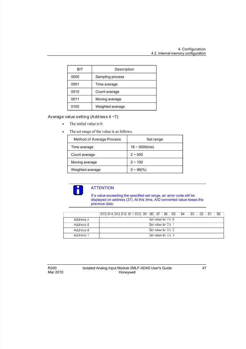
BIT Description
0000 Sampling process
0001 Time average
0010 Count average
0011 Moving average
0100 Weighted average
Average value sett ing (Address 4 ~7)
The initial value is 0.
The set range of the value is as follows.
Method of Average Process Set range
Time average 16 ~ 5000(ms)
Count average 2 ~ 500
Moving average 2 ~ 100
Weighted average 0 ~ 99(%)
ATTENTION
If a value exceeding the specified set range, an error code will bedisplayed on address (37). At this time, A/D converted value keeps theprevious data.
R200 Isolated Analog Input Module 2MLF-AD4S User's Guide 47Mar 2010 Honeywell
8/22/2019 Analog Input Card R200
http://slidepdf.com/reader/full/analog-input-card-r200 48/80
4. Configuration4.2. Internal memory configuration
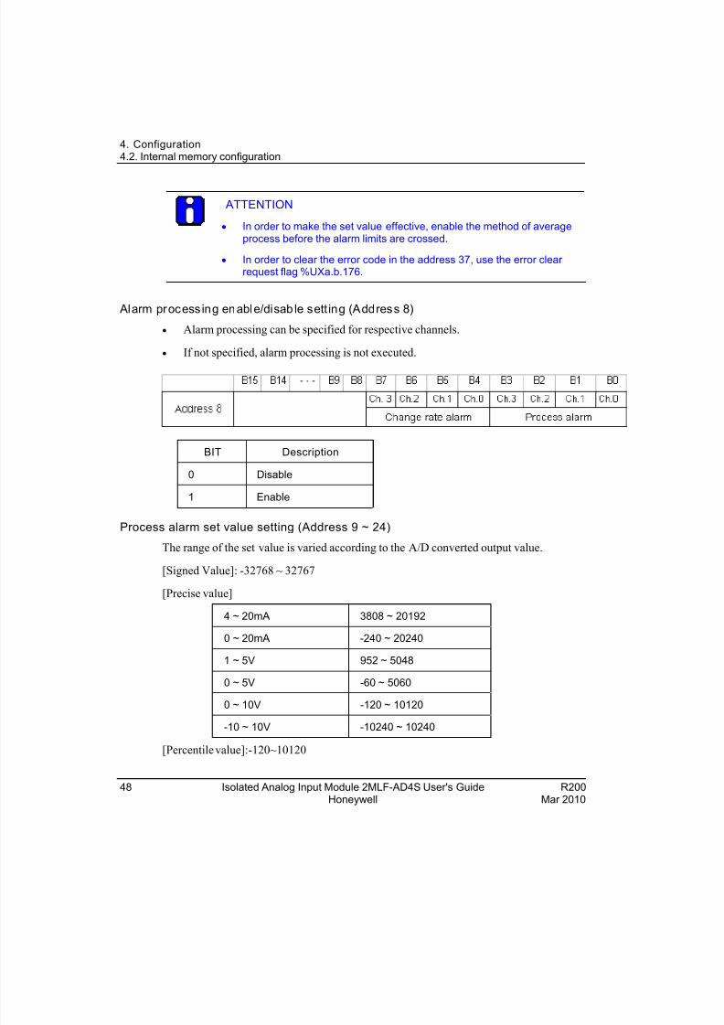
ATTENTION
In order to make the set value effective, enable the method of averageprocess before the alarm limits are crossed.
In order to clear the error code in the address 37, use the error clear request flag %UXa.b.176.
Alarm processing enable/disab le sett ing (Address 8)
Alarm processing can be specified for respective channels.
If not specified, alarm processing is not executed.
BIT Description
0 Disable
1 Enable
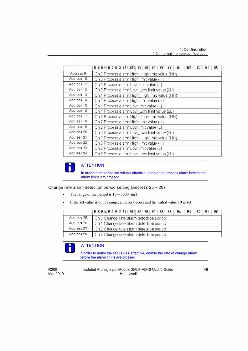
Process alarm set value setting (Address 9 ~ 24)
The range of the set value is varied according to the A/D converted output value.
[Signed Value]: -32768 ~ 32767
[Precise value]
4 ~ 20mA 3808 ~ 20192
0 ~ 20mA -240 ~ 20240
1 ~ 5V 952 ~ 5048
0 ~ 5V -60 ~ 5060
0 ~ 10V -120 ~ 10120
-10 ~ 10V -10240 ~ 10240
[Percentile value]:-120~10120
48 Isolated Analog Input Module 2MLF-AD4S User's Guide R200Honeywell Mar 2010
8/22/2019 Analog Input Card R200
http://slidepdf.com/reader/full/analog-input-card-r200 49/80
4. Configuration4.2. Internal memory configuration
ATTENTION
In order to make the set values effective, enable the process alarm before thealarm limits are crossed.
Change rate alarm detection period setting (Address 25 ~ 28)
The range of the period is 10 ~ 5000 (ms)
If the set value is out of range, an error occurs and the initial value 10 is set.
ATTENTION
In order to make the set values effective, enable the rate of change alarmbefore the alarm limits are crossed.
R200 Isolated Analog Input Module 2MLF-AD4S User's Guide 49Mar 2010 Honeywell
8/22/2019 Analog Input Card R200
http://slidepdf.com/reader/full/analog-input-card-r200 50/80
4. Configuration4.2. Internal memory configuration
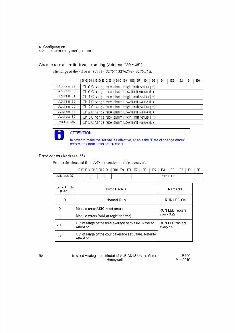
Change rate alarm lim it value setting (Address “ 29 ~ 36” )
The range of the value is -32768 ~ 32767(-3276.8% ~ 3276.7%).
ATTENTION
In order to make the set values effective, enable the “Rate of change alarm”before the alarm limits are crossed.
Error codes (Address 37)
Error codes detected from A/D conversion module are saved.
Error Code(Dec.)
Error Details Remarks
0 Normal Run RUN LED On
10 Module error(ASIC reset error)
11 Module error (RAM or register error).
RUN LED flickersevery 0.2s.
20Out of range of the time average set value. Refer to
Attention.
30 Out of range of the count average set value. Refer to Attention.
RUN LED flickersevery 1s.
50 Isolated Analog Input Module 2MLF-AD4S User's Guide R200Honeywell Mar 2010
8/22/2019 Analog Input Card R200
http://slidepdf.com/reader/full/analog-input-card-r200 51/80
4. Configuration4.2. Internal memory configuration
R200 Isolated Analog Input Module 2MLF-AD4S User's Guide 51Mar 2010 Honeywell
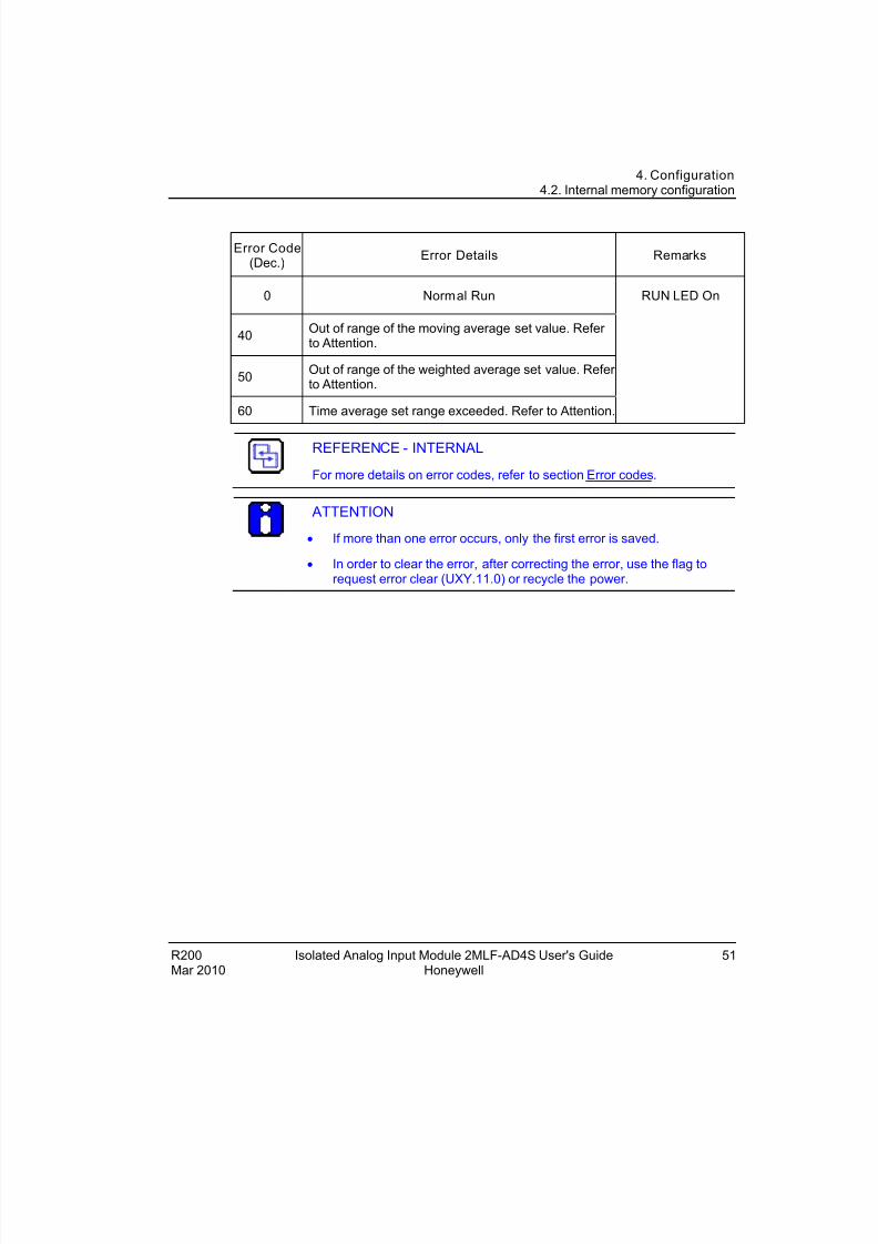
Error Code(Dec.)
Error Details Remarks
0 Normal Run RUN LED On
40Out of range of the moving average set value. Refer to Attention.
50Out of range of the weighted average set value. Refer to Attention.
60 Time average set range exceeded. Refer to Attention.
REFERENCE - INTERNAL
For more details on error codes, refer to section Error codes.
ATTENTION
If more than one error occurs, only the first error is saved.
In order to clear the error, after correcting the error, use the flag torequest error clear (UXY.11.0) or recycle the power.

8/22/2019 Analog Input Card R200
http://slidepdf.com/reader/full/analog-input-card-r200 52/80
4. Configuration4.2. Internal memory configuration
52 Isolated Analog Input Module 2MLF-AD4S User's Guide R200Honeywell Mar 2010
8/22/2019 Analog Input Card R200
http://slidepdf.com/reader/full/analog-input-card-r200 53/80
R200 Isolated Analog Input Module 2MLF-AD4S User's Guide 53
5. Operation and Monitoring
5.1 Setting the operation parameters
There are two ways to set the operation parameters.
I/O Parameter configuration in SoftMaster
Using Ladder program to configure the memory of the module.
REFERENCE – INTERNAL
For additional information on user program settings, refer to sectionConfiguration of analog input module.
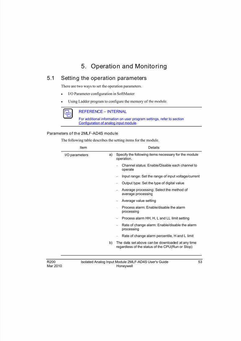
Parameters o f the 2MLF-AD4S module
The following table describes the setting items for the module.
Item Details
I/O parameters a) Specify the following items necessary for the moduleoperation.
Channel status: Enable/Disable each channel tooperate
Input range: Set the range of input voltage/current
Output type: Set the type of digital value
Average processing: Select the method of average processing
Average value setting
Process alarm: Enable/disable the alarmprocessing
Process alarm HH, H, L and LL limit setting
Rate of change alarm: Enable/disable the alarmprocessing
Rate of change alarm percentile, H and L limit
b) The data set above can be downloaded at any timeregardless of the status of the CPU(Run or Stop)
Mar 2010 Honeywell
8/22/2019 Analog Input Card R200
http://slidepdf.com/reader/full/analog-input-card-r200 54/80
5. Operation and Monitoring5.1. Setting the operation parameters
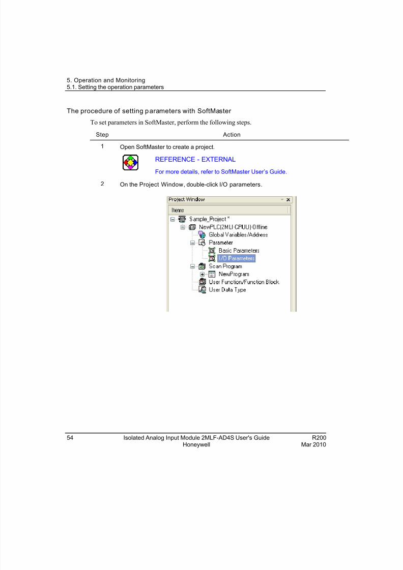
The procedure of setting parameters with SoftMaster
To set parameters in SoftMaster, perform the following steps.
Step Action
Open SoftMaster to create a project.1
REFERENCE - EXTERNAL
For more details, refer to SoftMaster User’s Guide.
2 On the Project Window, double-click I/O parameters.
54 Isolated Analog Input Module 2MLF-AD4S User's Guide R200Honeywell Mar 2010
8/22/2019 Analog Input Card R200
http://slidepdf.com/reader/full/analog-input-card-r200 55/80
5. Operation and Monitoring5.1. Setting the operation parameters
R200 Isolated Analog Input Module 2MLF-AD4S User's Guide 55Mar 2010 Honeywell
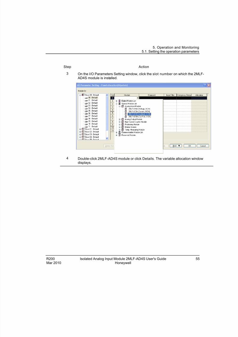
Step Action
3 On the I/O Parameters Setting window, click the slot number on which the 2MLF- AD4S module is installed.
4 Double-click 2MLF-AD4S module or click Details. The variable allocation windowdisplays.
8/22/2019 Analog Input Card R200
http://slidepdf.com/reader/full/analog-input-card-r200 56/80
5. Operation and Monitoring5.1. Setting the operation parameters
56 Isolated Analog Input Module 2MLF-AD4S User's Guide R200Honeywell Mar 2010
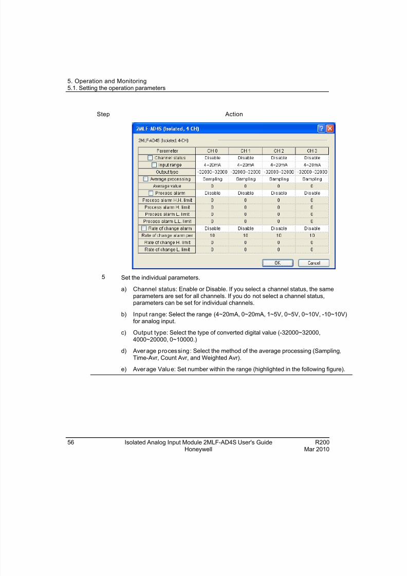
Step Action
5 Set the individual parameters.
a) Channel status: Enable or Disable. If you select a channel status, the sameparameters are set for all channels. If you do not select a channel status,
parameters can be set for individual channels.
b) Input range: Select the range (4~20mA, 0~20mA, 1~5V, 0~5V, 0~10V, -10~10V)for analog input.
c) Output type: Select the type of converted digital value (-32000~32000,4000~20000, 0~10000.)
d) Average processing : Select the method of the average processing (Sampling,Time-Avr, Count Avr, and Weighted Avr).
e) Average Value: Set number within the range (highlighted in the following figure).
8/22/2019 Analog Input Card R200
http://slidepdf.com/reader/full/analog-input-card-r200 57/80
5. Operation and Monitoring5.1. Setting the operation parameters
R200 Isolated Analog Input Module 2MLF-AD4S User's Guide 57Mar 2010 Honeywell
Step Action
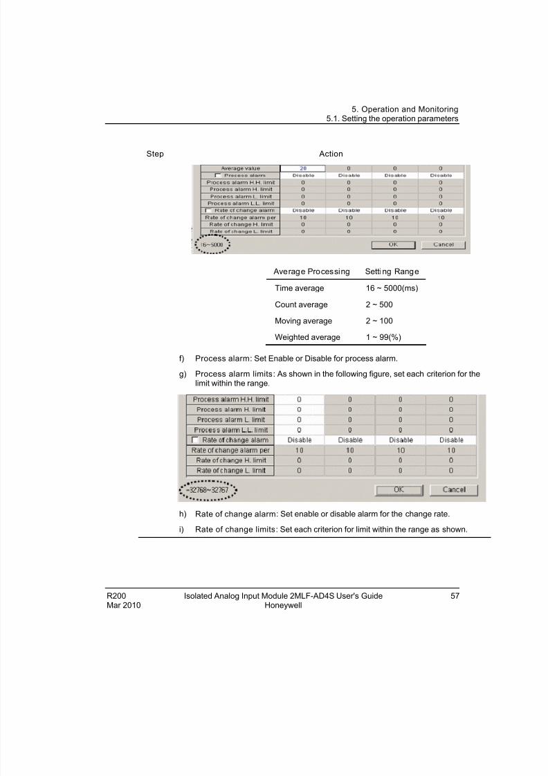
Average Processing Setting Range
Time average 16 ~ 5000(ms)
Count average 2 ~ 500
Moving average 2 ~ 100
Weighted average 1 ~ 99(%)
f) Process alarm: Set Enable or Disable for process alarm.
g) Process alarm limits: As shown in the following figure, set each criterion for thelimit within the range.
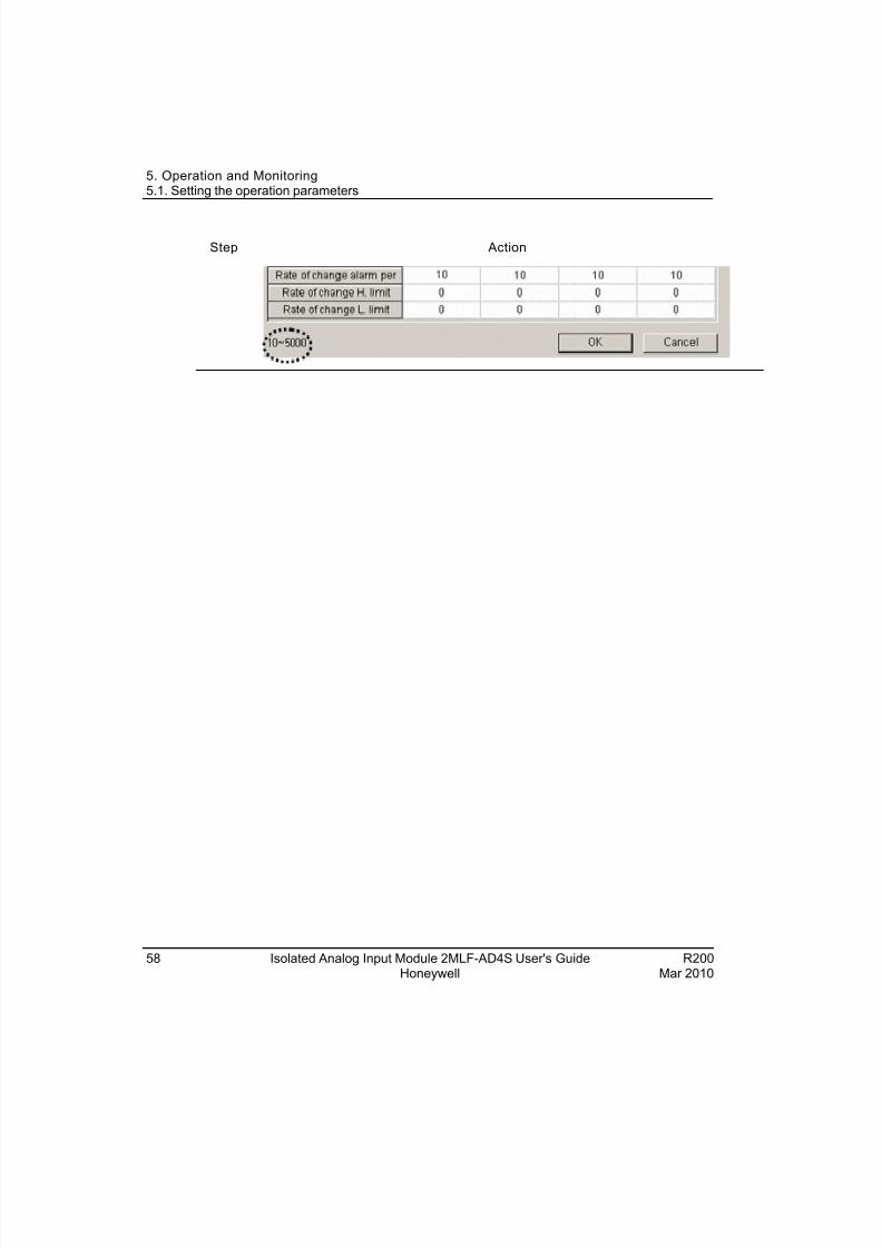
h) Rate of change alarm: Set enable or disable alarm for the change rate.
i) Rate of change limits: Set each criterion for limit within the range as shown.
8/22/2019 Analog Input Card R200
http://slidepdf.com/reader/full/analog-input-card-r200 58/80
5. Operation and Monitoring5.1. Setting the operation parameters
58 Isolated Analog Input Module 2MLF-AD4S User's Guide R200Honeywell Mar 2010
Step Action
8/22/2019 Analog Input Card R200
http://slidepdf.com/reader/full/analog-input-card-r200 59/80
5. Operation and Monitoring5.2. Special module registration
5.2 Special module registration
Registering special module
The isolated analog input module is automatically registered from SoftMaster.
It registers the variables for each module referring to the special module information that
is set in the I/O parameter. The variables and comments can be modified.
Perform the following steps for automatic registration of the isolated analog input
module in SoftMaster.
Step Action
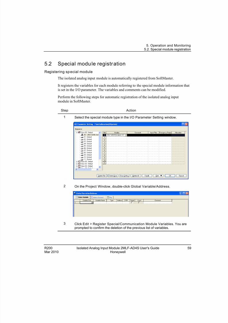
1 Select the special module type in the I/O Parameter Setting window.
2 On the Project Window, double-click Global Variable/Address.
3 Click Edit > Register Special/Communication Module Variables. You areprompted to confirm the deletion of the previous list of variables.
R200 Isolated Analog Input Module 2MLF-AD4S User's Guide 59Mar 2010 Honeywell
8/22/2019 Analog Input Card R200
http://slidepdf.com/reader/full/analog-input-card-r200 60/80
5. Operation and Monitoring5.2. Special module registration
60 Isolated Analog Input Module 2MLF-AD4S User's Guide R200Honeywell Mar 2010
Step Action
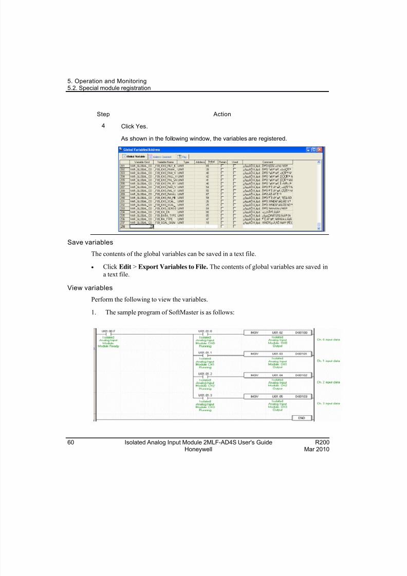
4 Click Yes.
As shown in the following window, the variables are registered.
Save variables
The contents of the global variables can be saved in a text file.
Click Edit > Export Variables to File. The contents of global variables are saved in
a text file.
View variables
Perform the following to view the variables.1. The sample program of SoftMaster is as follows:
8/22/2019 Analog Input Card R200
http://slidepdf.com/reader/full/analog-input-card-r200 61/80
5. Operation and Monitoring5.2. Special module registration
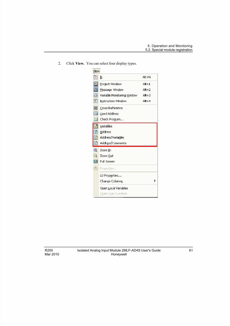
2. Click View. You can select four display types.
R200 Isolated Analog Input Module 2MLF-AD4S User's Guide 61Mar 2010 Honeywell
8/22/2019 Analog Input Card R200
http://slidepdf.com/reader/full/analog-input-card-r200 62/80
5. Operation and Monitoring5.3. Monitoring special modules
5.3 Monitor ing special modules
Monitoring 2MLF AD4S
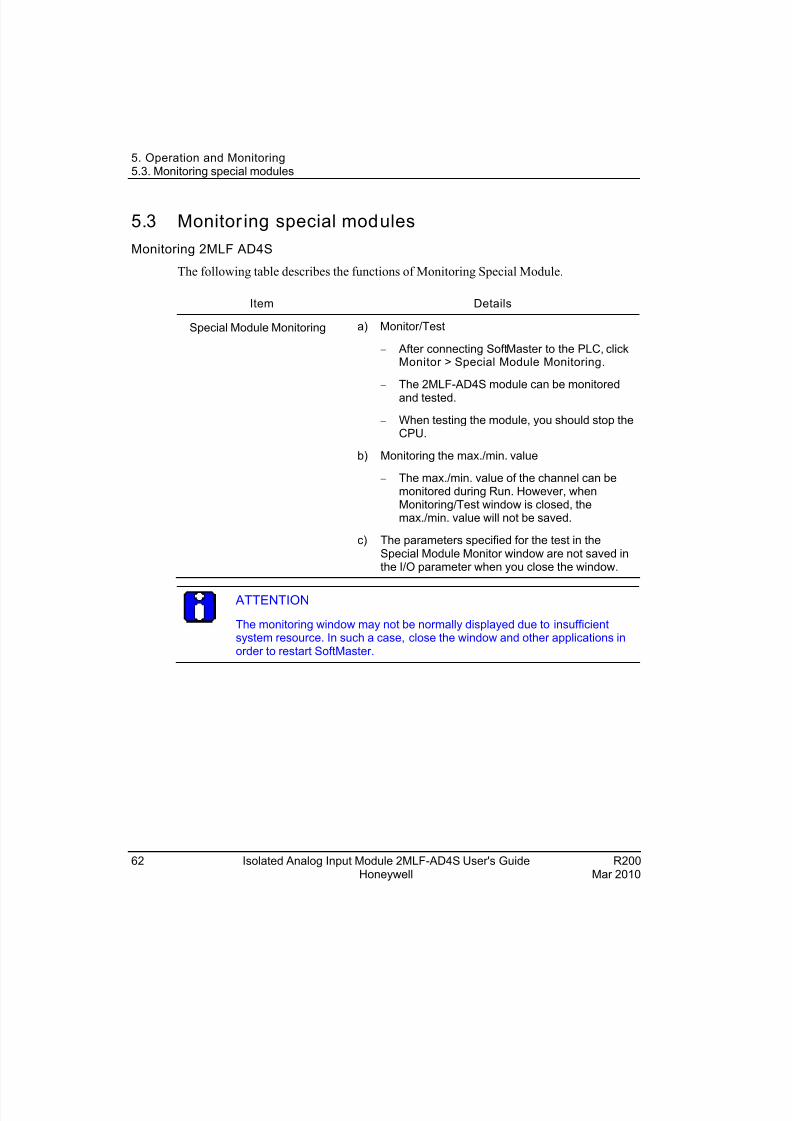
The following table describes the functions of Monitoring Special Module.
Item Details
Special Module Monitoring a) Monitor/Test
After connecting SoftMaster to the PLC, clickMonitor > Special Module Monitoring.
The 2MLF-AD4S module can be monitoredand tested.
When testing the module, you should stop theCPU.
b) Monitoring the max./min. value
The max./min. value of the channel can bemonitored during Run. However, whenMonitoring/Test window is closed, themax./min. value will not be saved.
c) The parameters specified for the test in theSpecial Module Monitor window are not saved inthe I/O parameter when you close the window.
ATTENTION
The monitoring window may not be normally displayed due to insufficientsystem resource. In such a case, close the window and other applications inorder to restart SoftMaster.
62 Isolated Analog Input Module 2MLF-AD4S User's Guide R200Honeywell Mar 2010
8/22/2019 Analog Input Card R200
http://slidepdf.com/reader/full/analog-input-card-r200 63/80
5. Operation and Monitoring5.3. Monitoring special modules
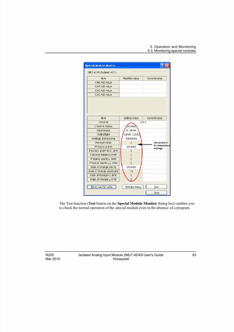
The Test function (Test button on the Special Module Monitor dialog box) enables youto check the normal operation of the special module even in the absence of a program.
R200 Isolated Analog Input Module 2MLF-AD4S User's Guide 63Mar 2010 Honeywell
8/22/2019 Analog Input Card R200
http://slidepdf.com/reader/full/analog-input-card-r200 64/80
5. Operation and Monitoring5.3. Monitoring special modules
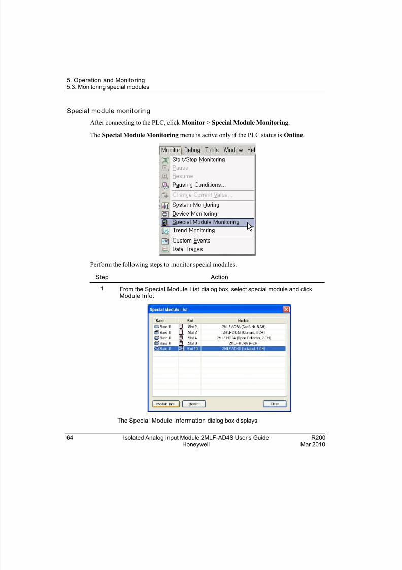
Special module monitoring
After connecting to the PLC, click Monitor > Special Module Monitoring.
The Special Module Monitoring menu is active only if the PLC status is Online.
Perform the following steps to monitor special modules.
Step Action
1 From the Special Module List dialog box, select special module and clickModule Info.
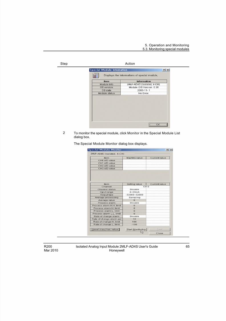
The Special Module Information dialog box displays.
64 Isolated Analog Input Module 2MLF-AD4S User's Guide R200Honeywell Mar 2010
8/22/2019 Analog Input Card R200
http://slidepdf.com/reader/full/analog-input-card-r200 65/80
5. Operation and Monitoring5.3. Monitoring special modules
R200 Isolated Analog Input Module 2MLF-AD4S User's Guide 65Mar 2010 Honeywell
Step Action
2 To monitor the special module, click Monitor in the Special Module List dialog box.
The Special Module Monitor dialog box displays.
8/22/2019 Analog Input Card R200
http://slidepdf.com/reader/full/analog-input-card-r200 66/80
5. Operation and Monitoring5.3. Monitoring special modules
66 Isolated Analog Input Module 2MLF-AD4S User's Guide R200Honeywell Mar 2010
Step Action
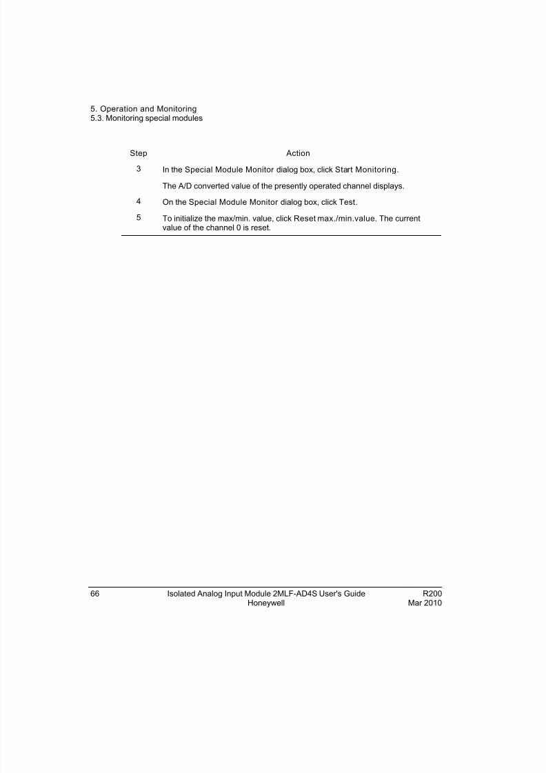
3 In the Special Module Monitor dialog box, click Start Monitoring.
The A/D converted value of the presently operated channel displays.
4 On the Special Module Monitor dialog box, click Test.
5 To initialize the max/min. value, click Reset max./min.value. The currentvalue of the channel 0 is reset.
8/22/2019 Analog Input Card R200
http://slidepdf.com/reader/full/analog-input-card-r200 67/80
R200 Isolated Analog Input Module 2MLF-AD4S User's Guide 67
6. Programming
6.1 Setting the operating parameters
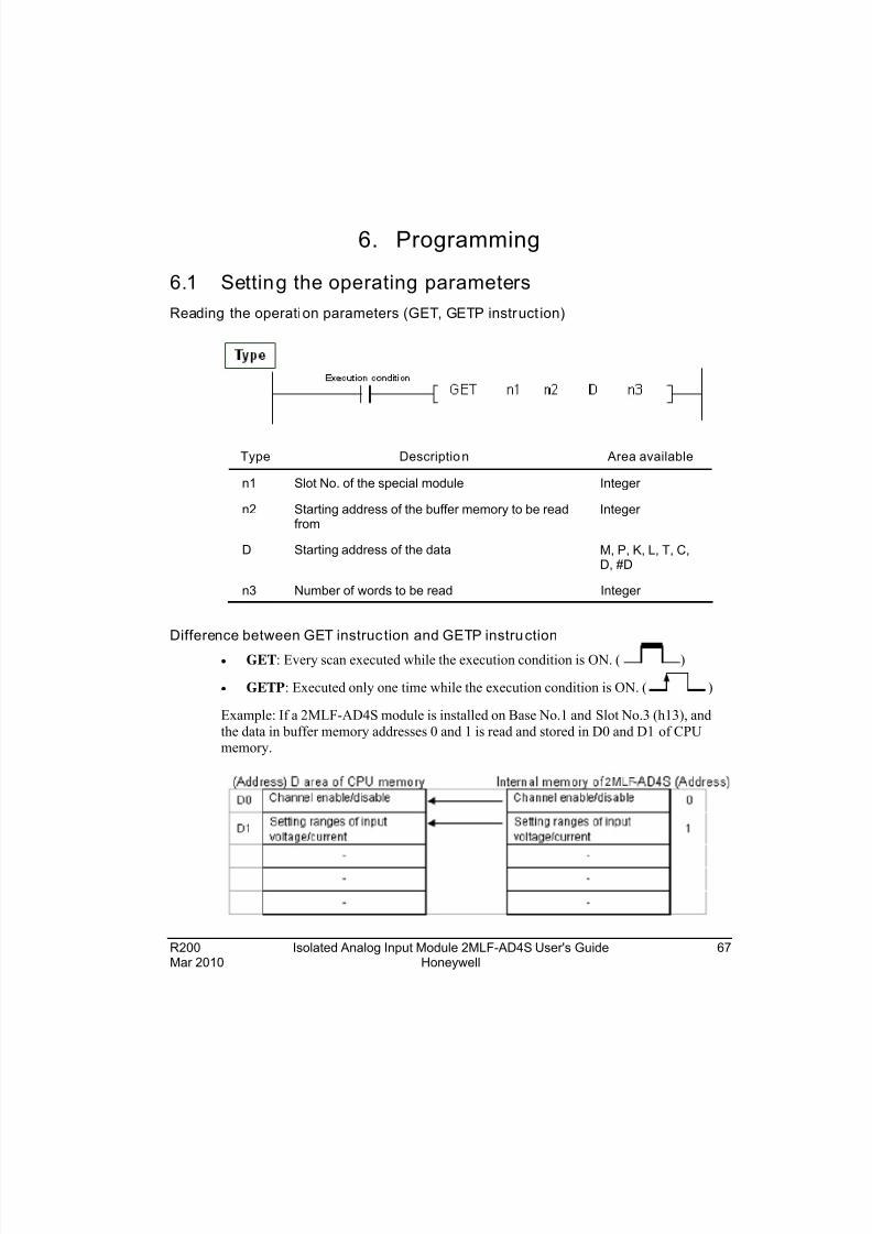
Reading the operation parameters (GET, GETP instruct ion)
Type Description Area available
n1 Slot No. of the special module Integer
n2 Starting address of the buffer memory to be readfrom
Integer
D Starting address of the data M, P, K, L, T, C,D, #D
n3 Number of words to be read Integer
Difference between GET instruc tion and GETP instruction
GET: Every scan executed while the execution condition is ON. ( )
GETP: Executed only one time while the execution condition is ON. ( )
Example: If a 2MLF-AD4S module is installed on Base No.1 and Slot No.3 (h13), and
the data in buffer memory addresses 0 and 1 is read and stored in D0 and D1 of CPUmemory.
Mar 2010 Honeywell
8/22/2019 Analog Input Card R200
http://slidepdf.com/reader/full/analog-input-card-r200 68/80
6. Programming6.1. Setting the operating parameters
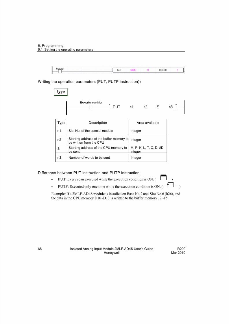
Writing the operation parameters (PUT, PUTP instruction))
Type Description Area available
n1 Slot No. of the special module Integer
n2 Starting address of the buffer memory tobe written from the CPU
Integer
S Starting address of the CPU memory tobe sent
M, P, K, L, T, C, D, #D,integer
n3 Number of words to be sent Integer
Difference between PUT instruction and PUTP instruction
PUT: Every scan executed while the execution condition is ON. ( )
PUTP: Executed only one time while the execution condition is ON. ( )
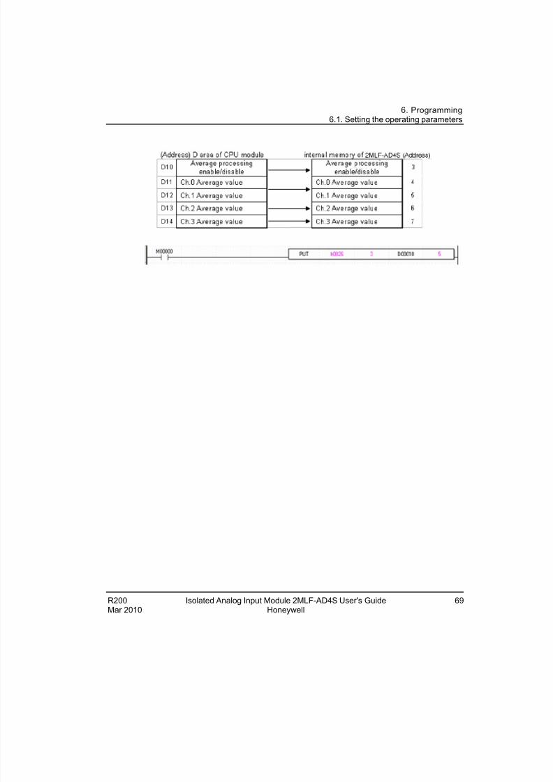
Example: If a 2MLF-AD4S module is installed on Base No.2 and Slot No.6 (h26), and
the data in the CPU memory D10~D13 is written to the buffer memory 12~15.
68 Isolated Analog Input Module 2MLF-AD4S User's Guide R200Honeywell Mar 2010
8/22/2019 Analog Input Card R200
http://slidepdf.com/reader/full/analog-input-card-r200 69/80
6. Programming6.1. Setting the operating parameters
R200 Isolated Analog Input Module 2MLF-AD4S User's Guide 69Mar 2010 Honeywell
8/22/2019 Analog Input Card R200
http://slidepdf.com/reader/full/analog-input-card-r200 70/80
6. Programming6.2. Basic program
6.2 Basic program
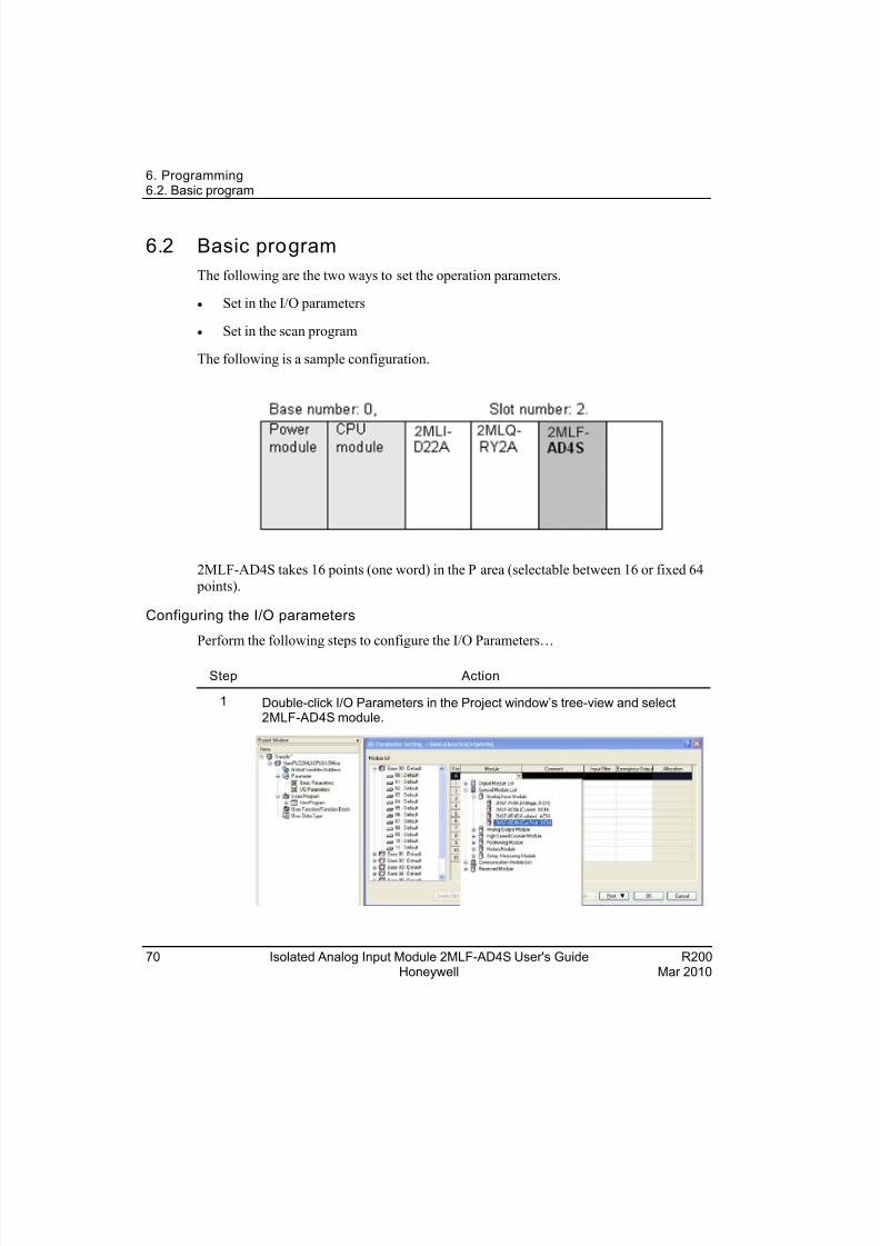
The following are the two ways to set the operation parameters.
Set in the I/O parameters
Set in the scan program
The following is a sample configuration.
2MLF-AD4S takes 16 points (one word) in the P area (selectable between 16 or fixed 64
points).
Configuring the I/O parameters
Perform the following steps to configure the I/O Parameters…
Step Action
1 Double-click I/O Parameters in the Project window’s tree-view and select2MLF-AD4S module.
70 Isolated Analog Input Module 2MLF-AD4S User's Guide R200Honeywell Mar 2010
8/22/2019 Analog Input Card R200
http://slidepdf.com/reader/full/analog-input-card-r200 71/80
6. Programming6.2. Basic program
R200 Isolated Analog Input Module 2MLF-AD4S User's Guide 71Mar 2010 Honeywell
Step Action
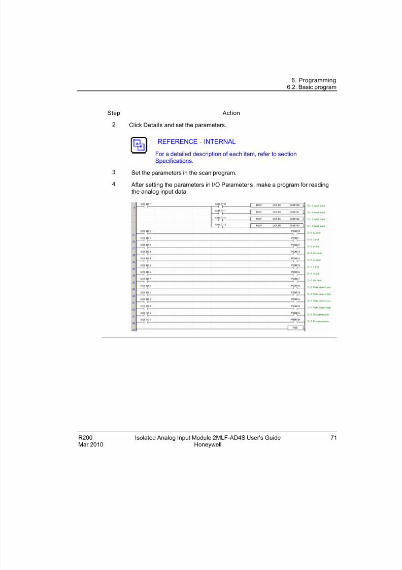
Click Details and set the parameters.2
REFERENCE - INTERNAL
For a detailed description of each item, refer to sectionSpecifications.
3 Set the parameters in the scan program.
4 After setting the parameters in I/O Parameters, make a program for readingthe analog input data.
8/22/2019 Analog Input Card R200
http://slidepdf.com/reader/full/analog-input-card-r200 72/80
6. Programming6.2. Basic program
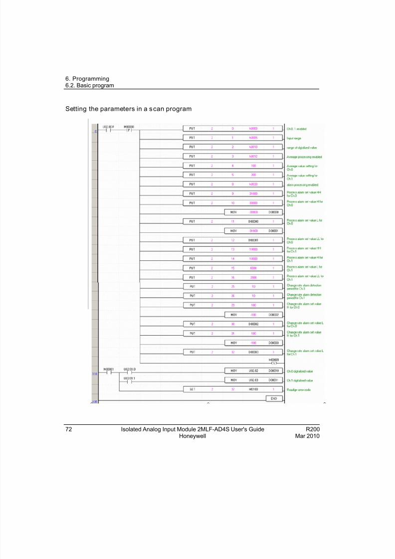
Setting the parameters in a scan program
72 Isolated Analog Input Module 2MLF-AD4S User's Guide R200Honeywell Mar 2010
8/22/2019 Analog Input Card R200
http://slidepdf.com/reader/full/analog-input-card-r200 73/80
R200 Isolated Analog Input Module 2MLF-AD4S User's Guide 73
7. Troubleshooting
7.1 Checking operation status
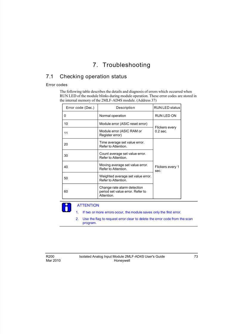
Error codes
The following table describes the details and diagnosis of errors which occurred whenRUN LED of the module blinks during module operation. These error codes are stored in
the internal memory of the 2MLF-AD4S module. (Address 37)
Error code (Dec.) Description RUN LED status
0 Normal operation RUN LED ON
10 Module error (ASIC reset error)
11Module error (ASIC RAM or Register error)
Flickers every0.2 sec.
20Time average set value error.Refer to Attention.
30Count average set value error.Refer to Attention.
40Moving average set value error.Refer to Attention.
50 Weighted average set value error.Refer to Attention.
60Change rate alarm detectionperiod set value error. Refer to
Attention.
Flickers every 1sec.
ATTENTION
1. If two or more errors occur, the module saves only the first error.
2. Use the flag to request error clear to delete the error code from the scanprogram.
Mar 2010 Honeywell
8/22/2019 Analog Input Card R200
http://slidepdf.com/reader/full/analog-input-card-r200 74/80
7. Troubleshooting7.2. Troubleshooting
7.2 Troubleshooting
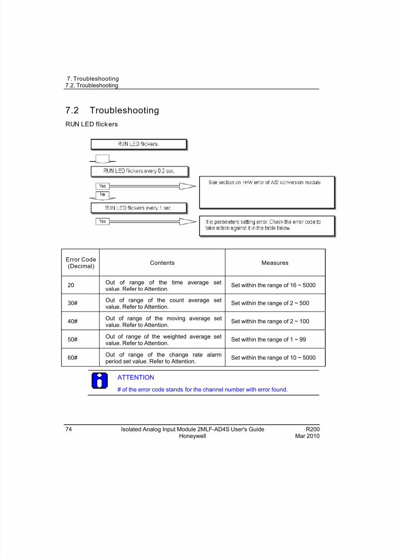
RUN LED flickers
Error Code(Decimal)
Contents Measures
20Out of range of the time average setvalue. Refer to Attention.
Set within the range of 16 ~ 5000
30#Out of range of the count average setvalue. Refer to Attention.
Set within the range of 2 ~ 500
40#Out of range of the moving average setvalue. Refer to Attention.
Set within the range of 2 ~ 100
50#Out of range of the weighted average setvalue. Refer to Attention.
Set within the range of 1 ~ 99
60#Out of range of the change rate alarmperiod set value. Refer to Attention.
Set within the range of 10 ~ 5000
ATTENTION
# of the error code stands for the channel number with error found.
74 Isolated Analog Input Module 2MLF-AD4S User's Guide R200Honeywell Mar 2010
8/22/2019 Analog Input Card R200
http://slidepdf.com/reader/full/analog-input-card-r200 75/80
7. Troubleshooting7.2. Troubleshooting
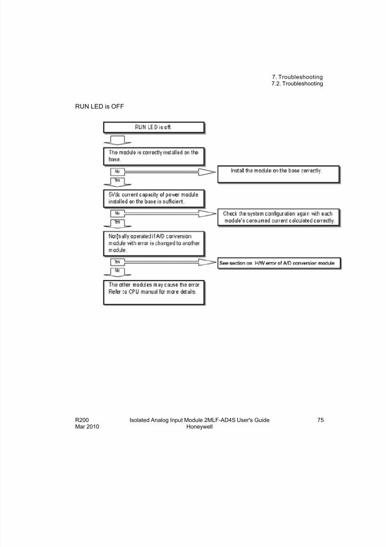
RUN LED is OFF
R200 Isolated Analog Input Module 2MLF-AD4S User's Guide 75Mar 2010 Honeywell
8/22/2019 Analog Input Card R200
http://slidepdf.com/reader/full/analog-input-card-r200 76/80
7. Troubleshooting7.2. Troubleshooting
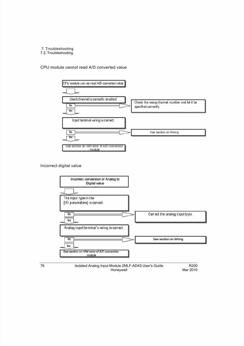
CPU module cannot read A/D converted value
Incorrect digital value
76 Isolated Analog Input Module 2MLF-AD4S User's Guide R200Honeywell Mar 2010
8/22/2019 Analog Input Card R200
http://slidepdf.com/reader/full/analog-input-card-r200 77/80
7. Troubleshooting7.2. Troubleshooting
R200 Isolated Analog Input Module 2MLF-AD4S User's Guide 77Mar 2010 Honeywell
H/W error of A/D conversion module
CAUTIONSwitch the power ON/OFF again.
If the error recurs again, it may be a module defect. Contact TAC for support.
Checking operation status from SoftMaster system monitoring
Module type, module information, O/S version and module status of the module can bechecked using the SoftMaster’s system monitoring function.
This can be executed in two ways.
1. Click Monitor > System Monitoring and right-click to display ModuleInformation.
2. Click Monitor > System Monitoring and double-click the module.
Module information
1. Module info: Shows type of the module.
2. O/S version: Shows the OS version of the module.
3. O/S date: Shows the build date of the O/S.
4. Module status: Shows the present error code.
8/22/2019 Analog Input Card R200
http://slidepdf.com/reader/full/analog-input-card-r200 78/80
7. Troubleshooting7.3. Dimensions
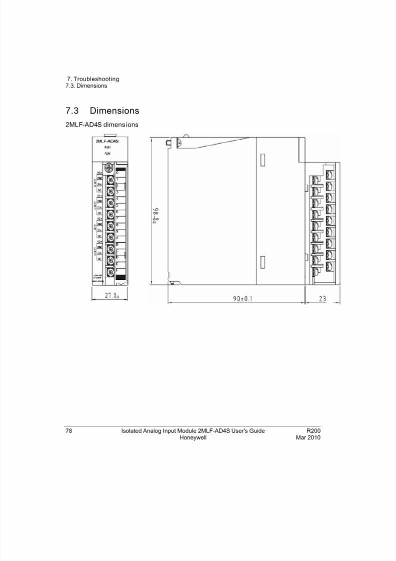
7.3 Dimensions
2MLF-AD4S dimens ions
78 Isolated Analog Input Module 2MLF-AD4S User's Guide R200Honeywell Mar 2010

8/22/2019 Analog Input Card R200
http://slidepdf.com/reader/full/analog-input-card-r200 79/80
7. Troubleshooting7.3. Dimensions
R200 Isolated Analog Input Module 2MLF-AD4S User's Guide 79Mar 2010 Honeywell

8/22/2019 Analog Input Card R200
http://slidepdf.com/reader/full/analog-input-card-r200 80/80