Embed Size (px)
Citation preview

N A S A C O N T R A C T O R
R E P O R T
CS|CMCS|
N A S A C R - 2 2 2 5
ANALYSIS OF HELICOPTER MANEUVER-LOADS
AND ROTOR-LOADS FLIGHT-TEST DATA
by Edward A. Beno
Prepared by
SIKORSKY AIRCRAFT DIVISION
UNITED AIRCRAFT CORPORATION
Stratford, Conn. 06602
for Langley Research Center ""
NATIONAL A E R O N A U T I C S AND SPACE ADMINISTRATION • WASHINGTON, D. C. • MARCH 1973
https://ntrs.nasa.gov/search.jsp?R=19730010269 2020-06-05T17:42:09+00:00Z

1. Report No.
NASA CR-2225
2. Government Accession No. 3. Recipient's Catalog No.
4. Title and Subtitle
> ANALYSIS OF HELICOPTER MANEUVER-LOADS AND ROTOR-LOADS FLIGHT-TEST DATA
5. Report DateMarch 1973
6. Performing Organization Code
7. Author(s)
Edward A. Beno
;'8: Performing Organization Report No.
10. Work Unit No.9. Performing Organization Name and Address
Sikorsky Aircraft DivisionUnited Aircraft CorporationStratford, CT
11. Contract or Grant No.NAS1-11049
12. Sponsoring Agency Name and Address
National Aeronautics and Space AdministrationWashington, D .C. 20546
13. Type of Report and Period Covered
Contractor Report
14. Sponsoring Agency Code
15. Supplementary Notes
16. Abstract
A study was conducted in which available airload and blade response data for the NH-3A andCH-53A rotors were analyzed in an attempt to provide greater insight into the sources of rotorvibratory loads in both level and maneuvering flight. Primary emphasis in the study was placedon examining and understanding causes of high-frequency rotor control loads. Secondary objectiveswere (1) to examine the effect of number of rotor blades on hub vibratory shear forces and (2)to assess which of the many terms"appearing in the hub vibratory shear force expression were ofmost significance.
17. Key Words (Suggested by Author(s))
Helicopter rotorAirloadsControl loadsManeuver loads
18. Distribution Statement
Unclassified - Unlimited
19. Security Qassif. (of this report)
Unclassified
20. Security Classif. (of this page)
Unclassified
21. No. of Pages
93
22. Price
$3.00
For sale by the National Technical Information Service, Springfield, Virginia 22151

TABLE OF CONTENTS
Page
SUMMARY 1
INTRODUCTION 1
SYMBOLS . . . 2
DATA ACQUISITION AND REDUCTION s« • • 5
Instrumentation 6Data Processing 7Data Analysis Methods 8
ANALYSIS OF HIGH-FREQUENCY BLADE RESPONSE . . . . . . . . 9
Factors Affecting Blade Torsional Response 10
Effects of airspeed 10Effects of maneuvers 10Effects of blade/tip-vortex wake interactions 11Effects of advancing blade critical Mach number lliEffects of blade bending 15Effects of aerodynamic pitching moments 16
Correlation with Analytically Derived Results 18
Description of programs and procedures. . 18Discussion of results ...'..' -19
ANALYSIS OF ROTOR VIBRATORY FORCE DATA 21
Major Blade Hinge Force Dynamic Terms 21Major Rotor Hub Force Dynamic Terms 23Effects of the Number of Main Rotor Blades on Harmonics
of Blade Hinge Forces 2U
CONCLUSIONS 25
RECOMMENDATIONS 26
REFERENCES.
ill

ANALYSIS OF HELICOPTER MANEUVER-LOADS
AND ROTOR-LOADS FLIGHT-TEST DATA
By Edward A. BenoSikorsky Aircraft DivisionUnited Aircraft Corporation
SUMMARY
A study was conducted in which available airload and blade response datafor the NH-3A and CH-53A rotors were analyzed in an attempt to provide greaterinsight into the sources of rotor vibratory loads in both level and maneuveringflight. Primary emphasis in the study was placed on examining and understand-ing causes of high-frequency rotor control loads. Secondary objectives were(l) to examine the effect of number of rotor blades on hub vibratory shearforces and (2) to assess which of the many terms appearing in the hub vibra-tory shear force expressions were of most significance.
Although stall flutter is probably a major contributor to high-frequencycontrol load oscillations when operating well above the knee of the controlload curvej it was found for the less stalled conditions analyzed in this studythat the principal high-frequency control load cause appears to be a forced dy-namic response of the blade to the time varying aerodynamic moment. Other fac-tors previously considered to be potentially important, such as moments inducedby blade/tip-vortex interactions or blade bending, were generally small for theconditions studied.
Analysis of the hub vibratory shear forces indicated that the nondimen-sionalized force harmonics for the six-bladed rotor were generally higher thanthose for the five-bladed rotor. Care must be exercised in generalizing thisresult, however, inasmuch as detailed blade dynamic characteristics (e.g.natural frequencies) undoubtedly influence the comparison. Finally, a review"of the equations used to compute hub vibratory forces from measurements ofblade root dynamic response indicates that many of the dynamic correction termsdue to motion of the hub, blade cuff, and instrumented blade segment can beneglected.
INTRODUCTION
One of the current problems facing helicopter rotor designers is theflight envelope limitations imposed by high-speed and maneuvering flight con-ditions where high vibratory control loads are encountered. Expansion of theenvelope may be possible if the source or sources of these vibratory loads canbe established and accurate methods validated for their prediction.
Previous investigators have studied this problem including analysis ofthe effects of stall flutter, rotor inflow, and unsteady aerodynamics. The

present study sought an explanation of the cause of the vibratory control loadsmeasured on the NH-3A and the CH-53A, and the ability of available analyticalmethods to predict the measured blade response. References 1 and 2 have con-cluded that retreating blade oscillations can be the result of a complicatedseries of dynamic and aerodynamic events. Reference 3 postulated the source ofhigh oscillatory control loads to be a wake-induced forced response of the tor-sional degree-of-freedom. Vortex crossings in the wake were shown to have adirect correspondence with measured retreating blade cm oscillations. The studyreported herein investigated torsional response utilizing in-flight data pre-viously measured on the NH-3A and the CH-53A. Reference i| describes the measure-ment program on the NH-3A. The CH-53A data were acquired during a previous flighttest program funded by the Naval Air Systems Command under Contract NOw 63-0150-f,CO-UO (63-0150) and CO-UOR1 (63-0150).
Included in the present study was an analysis of the measured maneuveringand high-speed blade azimuthal responses. Analysis was limited to a relativelyfew rotor revolutions of flight data. An understanding of the source of re-treating blade torsional oscillations was sought and measured blade responsewas correlated with analytical calculations.
A secondary investigation covers an examination of the vibratory rotorloads on both the NH-3A and the CH-53A. Methods were sought from which therotating blade hinge force harmonics and the non-rotating vibratory hub forcescould be approximated with good accuracy from measurements at the root of oneblade. Comparisons of the hinge force harmonics were made between two rotorsystems having a different number of blades.
Robert H. Blackwell, Jr., Sikorsky Aircraft Division, United AircraftCorporation, assisted in performing the correlation of test data with analysis.
SYMBOLS
Values are given in both the International System of Units (Si) and U. S.Customary Units. The measurements and calculations were made in U. S. CustomaryUnits.
b number of main rotor blades
c blade chord, m (in.)
cm section pitching moment coefficient, m% pc2[«R(r/R
cn section loading coefficient,
rotor thrust coefficient/solidity ratio
C.I. constant inflow analysis

e "blade offset, m (in.)
F longitudinal rotor hub force, N (ib)
F* radial blade hinge force, N (ib)X
F blade radial force at inboard end of instrumented segment, N (ib)
F lateral rotor hub force, N (ib)
F* edgewise blade hinge force, N (ib)</
FZ vertical rotor hub force, N (ib)
F* vertical blade hinge force, N (ib)z
f/f frequency relative to cutoff
G- Gaussian coefficients
I mass moment of inertia of instrumented segment about flapping axis,N-m-sec2 (ib-in.-sec )
I mass moment of inertia of instrumented segment about lag axis,N-m-sec (lb-in.-sec )
J blade torsional mass moment of inertia, N-m-sec2 (lb-in.i-sec2)
K. section aerodynamic pitching moment factors, m (in. )
k_ blade root torsional spring constant, N-m/rad (in.-lb/rad)
H - section normal loading, N/m (ib/in.)
M root torsional structural moment, N-m (in.-lb)X
M aerodynamic pitching moment, N-m (in.-lb)x,a
M _ model root torsional structural moment, N-m (in.-lb)x,i
M blade flatwise bending moment, N-m (in.-lb)J"
M blade edgewise bending moment, N-m (in.-lb)Z
M Q advancing blade tip Mach number (r/R = 1.0, i|i = 90 deg)
m section aerodynamic pitching moment, N-m/m (in.-lb/in.)
m blade mass inboard of instrumented segment, kg (lb-sec2/in.)
mjs blade instrumented segment mass, kg (lb-sec2/ln.)

n/rev frequency of n-th harmonic, i.e., n times the main rotor frequency
p absolute pressure, N/m^ (psia)
p free stream static pressure, N/m (psia)
R rotor radius, m (in.)
r blade radial location, m (in.)
T modal contribution of aerodynamic pitching moment, N-m (in.-lb)
V forward airspeed, m/sec (kn)
V.I. variable inflow analysis
XI,X2,.. symbolic blade radial hinge force terms (see table II)
x^ radial coordinate in blade axis system of center of gravity ofinstrumented segment, m (in.)
x radial distance, in blade axis system, from inboard end of instru-mented segment to center of gravity of instrumented segment, m (in.)
x radial coordinate, in blade axis system, of center of gravity ofmass inboard of instrumented segment, m (in.)
x,, rotor head displacement in shaft rotating system radial direction,K / • \m (in.;
Yl, Y2,.. symbolic blade edgewise hinge force terms (see table II)
y blade chordwise location measured from leading edge, m (in.)
y edgewise coordinate, in blade axis system, of center of gravity ofmass inboard of instrumented segment, m (in.)
y rotor head in-plane displacement in shaft rotating system perpendi-cular to hub radial direction, m (in.)
Z1,Z2,.. symbolic blade vertical hinge force terms (see table II)
z vertical coordinate, in blade axis system, of center of gravity ofmass inboard of instrumented segment, m (in.)
z... rotor head vertical displacement in shaft rotating system, m (in.)n
3 blade root flapping angle, deg
Y blade root lag angle, deg

Ap differential pressure, N/m (psi)
Ax radial length of "blade instrumented segment, m (in.)
£ damping ratio
6 blade root pitch angle, deg
6™ blade root torsional elastic twist, deg
y advance ratio, VnR up mass density of air, kg/m^ (lb-sec /in. )
<|> phase angle associated with n-th harmonic, deg
i|» blade azimuth angle, deg
ft rotor angular velocity, rad/sec
cu , blade torsional natural frequency, rad/sec
Subscripts:
( ) cosine component of harmonic
( ),„, refers to summation of major terms
( ) n-th harmonic ordern
( ) sine component of harmonics
( ).. at the inboard end of the blade instrumented segment
( )_ at the outboard end of the blade instrumented segment
,-( ) refers to 5-bladed NH-3A rotor system
A ) refers to 6-bladed CH-53A rotor system
Miscellaneous:
( ) first derivative with respect to time
( ) second derivative with respect to time
DATA ACQUISITION AND REDUCTION
The data analyzed in the study reported herein were measured during pre-

vious NH-3A and CH-53A flight test programs. The flight tests were primarilyperformed to acquire data describing the aerodynamic and dynamic characteris-tics of each aircraft.
The NH-3A is a compound helicopter capable of not only high forward speedsbut also of varying rotor lift and drag. Two auxiliary turbojet engines and awing including a full-span flap provide the aircraft with these capabilities.The 18.90: m (62 ft) diameter main rotor is a 5-bladed fully articulated system.The -k deg twisted blades have a modified NACA 0012 airfoil section. Normalgross weight is 8560 kg (18900 Ib). A photograph of the NH-3A is included asfigure 1.
The CH-53A, a high speed assault transport helicopter, is capable offlight at higher gross weights than is the NH-3A. The aircraft was flown atboth 15860 kg (35000 Ib) and 190UO kg (U2000 Ib) gross weights. The 6-bladedfully articulated CH-53A main rotor has a diameter of 21.95 m (72 ft) and the-6 deg twisted blades have a modified NACA 0011 airfoil section. The CH-53A isshown in figure 2.
Instrumentation
An airborne data acquisition system was used to record the aerodynamicand dynamic characteristics of each aircraft. Approximately one hundred chan^-,nels of data were recorded on a magnetic tape recording system installed in thecabin of the aircraft. This harrow band system provided a continuous frequencymodulation multiplexed recording of each measurement. Signal conditioning ofthe multiplexed output signal was performed before the data were actually re-corded on the tape transport. Quasi-static data describing the recorded flightcondition were provided on 35 mm film that recorded photopanel measurements.The photopanel measurements included airspeed, altitude, rate of climb, rotorangular velocity, ambient atmospheric conditions, and aircraft attitude. Acomplete description of the instrumentation and data acquisition methods usedis included in reference k.
A dynamic data sampling signal, used for time reference, was provided inthe aircraft by a rotor azimuth pulse generator which divided a main rotor rev-olution into 5 deg increments. A slotted disc and optical system mounted onthe bottom of the main rotor shaft provided this 72/rev signal plus a I/revpulse used as the 0 deg azimuth reference. This corresponds to the instrumentedmain rotor blade aligned over the aircraft tail.
A block diagram of the airborne recording system used on the CH-53A isshown in figure 3. Basically the same system was utilized to record the NH-3Adata. The measured blade response data used in the study reported herein in-clude blade pressures; flatwise, edgewise, and torsional bending moments; andpushrod loads. The distribution of the miniature absolute and differentialpressure transducers on the instrumented blade is given in figure U. Absolutepressure transducers were used on the upper and lower surfaces of the bladespar while differential gages were installed through the blade pockets and tipcap. Bending moment measurements were distributed along the blade span to re-

cord the response of the blade.
Data Processing
The primary objective of this program was to perform a detailed analysisof a limited number of rotor revolutions of important flight data. The emphasiswas on high-speed and maneuvering flight conditions for both the NH-3A and theCH-53A. The maneuvering conditions considered in this program were comprisedof banked right-turn regimes. Left turn data were not available. For theNH-3A, the measured data were acquired only during the actual steady-stateperiod of each banked turn. The available CH-53A right-turn conditions, how-ever, included data measured in the trimmed level flight regime, through atransition period, and finally during the actual steady-state portion of thecoordinated turn. Therefore, the NH-3A data cycle studied for the turns con-sisted only of a rotor revolution during the actual banked turn. For the CH-53Amaneuver, three separate cycles were investigated; trimmed level flight, tran-sition, and steady-state coordinated banked turn. Table I describes each ofthe data cycles investigated in the high-frequency blade response part of thisstudy. Case numbers refer to those used in reference h and earlier CH-53Astudies. '
Processing of the measured data was initiated by the formation of oscil-lograph traces from the flight test magnetic (analog) tapes. These recordswere arranged to include the I/rev and 72/rev signals required for subsequentdata reduction. In order to retain possible high-frequency response of thetest data, a filtering cut-off frequency of 100 Hz was utilized during the gen-eration of the oscillograph rolls. This had the effect of filtering out un-wanted signal noise above 100 Hz while retaining real signal response at fre-quencies up to approximately 30/rev, depending on the rotor angular velocity.The signal amplitude response using the low pass filters having a cut-off fre-quency of 100 Hz is shown in figure 5.
Selection of the particular cycles of data to be used in the high-fre-quency blade response study were chosen by manual scanning of the oscillographtraces. For maneuvers and high-speed conditions the cycles chosen within eachregime, described in table I, were selected primarily on the basis of theirhigh-frequency torsional response content. For these cycles the oscillographroll data for each required measurement were reduced to punch card form.
The 72/rev signal included on the traces was used as a time step intervalat which the data were punched into cards. Each parameter was punched as a 73point time history corresponding to a 0 to 360 deg rotor azimuth period (5 degazimuth interval). Along with the actual dynamic data for each measurement,calibration factors from the traces were also punched on the cards for lateruse in conversion of the machine units to engineering units. The dynamic dataand calibration factors on the punch cards were input to a computer program forfinal processing.
A secondary study included in this report was an analysis of main rotorloads. Basic objectives were to determine the major dynamic terms that contri-bute to harmonics of blade hinge forces and b/rev hub loads and the effect of

the number of main rotor blades on harmonics of the hinge forces. This was ac-complished by an analysis of the existing data measured during the flight pro-grams on the NH-3A and CH-53A. Cases were chosen from the available data tocover a wide range of operating conditions.
Data Analysis Methods
Digital computer programs were utilized for final processing of themeasured flight-test data. The blade pressure, bending moment, and pushrodload data punched on cards from the oscillographs were converted to engineer-ing units and listed by one program. A second digital program was used duringthe original flight-test programs to calculate the blade hinge forces and non-rotating b/rev hub loads. From the measured data, the separate dynamic termscontributing to these loads could be calculated by an option in this program.
With laboratory and aircraft calibration factors, along with the oscillo-graph conversion factors punched on the cards, the machine unit blade responsedata on punched cards were first converted to engineering unit data by a com-puter program. This procedure gave the azimuthal history of the measured pa-rameters including response at frequencies up to 100 Hz (filtering cut-off fre-quency). For each aircraft, 33 measurements were listed in this form. Theseincluded 2h blade absolute and differential pressures at 75, 85, and 95 percentradial stations; 3 flatwise bending moments; 3 edgewise bending moments; 2 tor-sional moments; and the pushrod load. At stations where two absolute pressuretransducers were mounted, on the upper and lower blade surfaces, the differen-tial pressure time histories were also calculated. At each of the three bladeradial stations the measured chordwise distribution of pressure was then uti-lized to calculate the blade section loading (airload) and aerodynamic pitchingmoment time histories. The five chordwise pressure stations were at U.2, 15.8,30.0, 60.0, and 91.0 percent of chord. A Gaussian integration scheme was usedto calculate the time history of blade airload from the relation
5^ = c^E (AP)is^
Gi (1)
where G. are the Gaussian coefficients for the five chordwise stations from G,
corresponding to U.2 percent chord to G,- at 91-0 percent chord. The coefficients
are GI = 1/10, Gg = 1/10, G~ = 2/9, G^ = 16/U5, and G = 2/9. The aerodynamic
pitching moment about the blade feathering axis was also calculated from thepressures utilizing a trapezoidal distribution between the measured pressures.Leading- and trailing-edge differential pressures were assumed to be zero. Therelationship for calculation of the pitching moment is
5m. = E (Ap). , K.fy \ - r - i i jh. . i 1i~>\
"i —1 '
where Kj_ are blade geometry factors corresponding to the five chordwise stations

from K at U.2 percent chord to K at 91.0 percent chord. For each aircraft the
factors are
Factor
Kl
K2
K3
Kl*
K5
NH-3A
2m
3.11 X10~3
2.31
-U.88
-23.16
-25.21
. 2in.
k.82
3.58
-7.56
-35.89
-39.08
CH-53A
2m
6.32 X10~3
k.69
-9-90
-1*7.00
-51.17
. 2in.
9-79
7.27
-15 . 3U
-72.85
-79.32
From the section loading and aerodynamic pitching moments calculated in equa-tions (l) and (2), the azimuthal histories of section loading and pitching mo-ment coefficients were calculated.
The digital computer program used to calculate the dynamic terms contri-buting to the blade hinge forces and b/rev hub loads is described in detail inreference k. The Root Response Method is programmed to calculate azimuthalhistories of the blade hinge forces from measurements made at the root of theblade. These include flatwise and edgevise bending moments, blade tension,blade root.angles, and accelerations at the blade hinge. The resulting equa-tions, given in reference U include a large number of dynamic terms in each ofthe three orthogonal hinge forces: radial, F*; edgewise, F*; andx yvertical, F*. These terms are harmonically analyzed. Assuming each main rotorblade encounters the same loads azimuthally as the instrumented blade, the non-rotating system b/rev loads are then calculated. This computer program providedthe calculation of the separate terms required to determine the major terms con-tributing to the hinge forces and non-rotating loads. This program also pro-vided comparisons of the effects of the number of blades on these loads for boththe NH-3A and CH-53A measured data.
ANALYSIS OF HIGH-FREQUENCY BLADE RESPONSE
The output of the digital computer program used to process the test dataread from oscillograph traces provided the basis for a timewise study of high-frequency blade torsional response. It also made possible comparisons of dif-ferent conditions and different aircraft. Azimuthal time history plots referred

to in subsequent sections of the report are of two forms. Plots of level-flightconditions given in table I indicate an azimuthal range from 0 to UOO deg. Forthese plots the first 1*0 deg of the rotor revolution have -been repeated to en-able better visualization of any high-frequency blade response oscillations oc-curring near the tail region of the aircraft. Maneuvering conditions are plottedonly from 0 to 360 deg since for these regimes, the 0 and 360 deg azimuthvalues are generally different.
Factors Affecting Blade Torsional Response
The occurrence and magnitude of high-frequency blade torsional oscillationswas a primary objective of this study. To determine the effect of the operatingcondition on this response, various conditions were compared. Of specific in-terest was the buildup of loads either at high airspeeds or during maneuveringconditions. Analysis of the measured blade response included studies of bladepressures, section loading coefficients, section pitching moment coefficients,blade/tip-vortex wake interactions, blade bending, and aerodynamic pitchingmoments. The effects of these parameters on blade torsional response are dis-cussed in the following sections.
Effects of airspeed. - The effects of airspeed on the response of the NH-3A blade are shown in figure 6. On the advancing side of the rotor disc thesection loading coefficient, cn; section pitching moment coefficient, cm; andthe root torsional moment, Mx, are basically unaffected by a change in airspeed.On the retreating side, however, moderately higher cn and cm amplitudes general-ly exist at the higher airspeed but the frequency content is the same. Thechange in H^ is considerably different than that in cn and cm due to increasedairspeed. While the steady value of the root torsional moment remains approxi-mately the same, there is a large increase in the vibratory content. The fre-quency of the oscillations is between 6/rev and 7/rev which corresponds to theblade torsional natural frequency of 6.6/rev for the operating conditions shownin figure 6. The measured pushrod loads for these conditions similarly indicatea buildup of the retreating blade oscillations at the same frequencies.
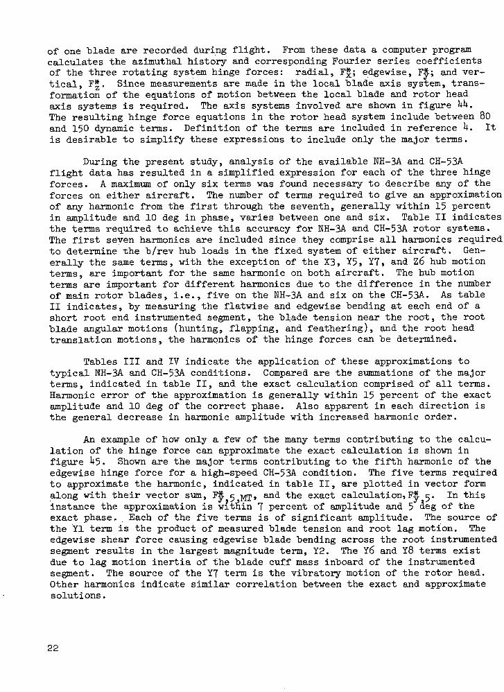
Effects of maneuvers. - To determine the effects of maneuvering flight onblade response, CH-53A cases UlLF (level flight), Ul TR (transition into abanked turn), and Ul TN (steady-state banked turn at a 60 deg angle of bank)were investigated. These effects are shown in figures 7, 8, and 9. An \increasein the steady value of cn can be noted in the typical data, shown at r/R\= 0.85in figure 7, as the aircraft progresses from level flight, through a transitionperiod, and finally into the 2g coordinated turn. This corresponds to increasedrotor thrust required to maintain attitude. Also shown is an increase in high-frequency content in the first and fourth quadrants of rotor azimuth for theturn. This is due to an increased effect of the instrumented blade passingcloser to the trailing vortices shed from preceding blades. Larger magnitudeoscillations occur in the fourth quadrant compared to those in the first.
Typical of the spanwise distributions for the same CH-53A maneuvering con-ditions, are the section pitching moment coefficients at r/R = 0.85 given infigure 8. Compared to level flight, the steady values of cm are not appreciablyaffected by the maneuvering conditions, but a definite increase in the higher
10

harmonic content is evident. The advancing side of the rotor disc experiencesseveral oscillations of very high frequency, above 30/rev, which also are prob-ably due to blade vortex crossings in the wake. In the vicinity of 270 deg az-imuth there is a growth of one small amplitude oscillation during level flight,into a short duration high amplitude .spike during transition, and finally intotwo separate high magnitude fluctuations in the turn cycle. Along with the gen-eration of the two spikes hear i|» = 270 deg, a third large amplitude fluctuationappeared in the region over the aircraft tail during the turn. Although instru-mentation attitude limitations prevented knowledge of the exact rotor orienta-tion with respect to the free stream during turns, it is believed that the largeamplitude cm variations are due to vortex crossing effects. Examination of themeasured blade pressures at r/R = 0.85 indicates that large excursions in thedifferential pressure at the k.2 percent chord station were the cause of thecorresponding cm fluctuations. These are discussed in a subsequent section ofthis report.
The cm data shown in figures 6 and 8 have indicated a steady leading edgeup condition existing for both the NH-3A and CH-53A conditions. Steady cm valuescalculated from measured pressures vary between 0.02 and 0.0 . Existing stan-dard NACA 0011 and 0012 steady and unsteady airfoil data, references 5 and 6,indicate that these positive steady values are unattainable over the angle ofattack and Mach-number environment experienced in the flight conditions. Thebasic NH-3A blade has a modified 0012 airfoil and a modified 0011 airfoil isused on standard CH-53A blades. However, both of the test instrumented bladeshad chordwise epoxy fairing bands covering the area around the surface mountedpressure transducers and a spanwise fairing over the instrumentation wiring tothe root of the blades. Details of the application and extent of these fairingsare given in reference U. It is possible, therefore, that these fairings, whichhad the effect of making the airfoil section unsymmetrical, may be the source ofresulting leading edge up pitching moments on the blade.
The existence of the positive pitching moments is also indicated in themeasured blade root torsional moments shown in figure 9. Increased harmoniccontent is also evident in the torsional moment as the steady-state turn cycleis attained. The high amplitude retreating blade torsional moment oscillationsduring the turn do not indicate a direct correlation with the cm fluctuationsshown in figure 8 due to variations of the cm distribution along the blade.The root torsional moment measurement records the integrated effect of loadingsalong the entire blade length.
Effects of blade/tip-vortex wake interactions. - For U-bladed E-3k maneu-vering conditions, reference 3 indicated that a direct correlation existed be-tween high-frequency retreating blade oscillations and the passage of each bladeby the tip vortices generated by preceding blades. In the present study, theavailable cases were investigated to determine whether this interaction existedfor the 5-bladed NH-3A or the 6-bladed CH-53A. It should be noted that the num-ber of blades and the advance ratio can affect the frequency and strength of theblade loads induced by the blade/vortex interactions. Also the sensivity of agiven blade design to such periodic excitation will, of course, depend on theblade natural frequencies.
11

The non-distorted helical pattern of the blade tip vortex trajectories isshown in figure 10 for NH-3A case 72. Shown is a view from above and perpendi-cular to the rotor tip path plane. Indicated in the figure are the plan viewintersections of the 95 percent blade station with the wake pattern formed fromthe tip vortex of each blade. Three of these crossings occur in the fourthrotor quadrant and six in the first quadrant. These intersections representpossible blade/wake interactions, but the proximity of the blade and the tipvortices, along with the circulation strength, depend on the rotor orientationwith respect to the free stream and the wake inflow velocities.
The azimuthal histories of blade differential pressures at 75, 85, and 95percent radial stations are shown in figures 11, 12, and 13 for NH-3A case 72.Included within the plots are the azimuthal locations of possible blade/wakeinteractions determined from the helical wake pattern shown in figure 10. In-dicated are the intersections of the tip vortices with the blade radial stationcorresponding to the plotted blade pressures. These locations also indicatethe directional sense of the tip vortex tangential velocity as the instrumentedblade approaches. Figures 11, 12, and 13 do not indicate, for NH-3A case 72,any strong correlation between the possible first quadrant vortex crossings andthe pressure response. In general the pressure variations across the chord ap-pear to behave similarly except at the 30.0 percent, and to a lesser extent atthe 15.8 percent, chord station on the advancing blade at 85 and 95 percent ra-dial stations. These fluctuations, in the general shape of a square wave, ap-pear to be due to a critical Mach-number effect which will be discussed in thesucceeding report section. They are not believed to be the result of any blade/wake intersections. On the retreating side of the disc there is evidence ofprobable vortex crossing effects, the strongest occurring at approximately 280deg azimuth where relatively rapid pressure fluctuations correspond to a possi-ble crossing at the same time. However, other lower frequency pressure oscilla-tions occur where vortex crossings do not appear to exist, such as those thatinitiate at the 85 and 95 percent blade stations over the nose of the aircraft.Vortex crossings are unlikely in this region since, as can be seen in figure 10,the blades are approaching undisturbed air.
Based on the pressures shown in figures 11, 12, and 13, the NH-3A rightturn at a 60 deg angle of bank does not appear to exhibit a strong correlationbetween the possible blade/vortex crossings and the measured pressure response.However, this maneuver condition did display a limited effect while the steadystate level flight conditions that were analyzed did not exhibit any noticeableeffect of the blade/vortex crossings.
In figure lU, the cn and c time histories, calculated from the measuredpressures at r/R = 0.95, shown in figure 13, are plotted along with the tor-sional moment measured at the root of the blade. Included in the cm plot arethe possible vortex crossings with the 95 percent blade radial station, deter-mined from the plan view of the non-distorted tip vortex trajectories. No ap-preciable oscillations occur in c or cm on the advancing blade other than onenear ty = 1*0 deg which is attributable to the critical Mach-number effect dis-cussed in the following section. On the retreating side, however, several os-cillations occur in both cn and cm, two of which agree fairly well in phasewith, vortex crossings at 2o7 and 317 deg azimuth. Comparison of the measured
12

root torsional moment in figure ±k with the azimuthal locations of possibleblade/vortex crossings shows that the torsional moment oscillations initiate at180 deg azimuth, prior to any possible crossings. In fact the largest torsionalmoment oscillation occurs prior to the first helix crossing with the 95 percentspan of the blade. The cm distributions at 75 and 85 percent blade span (notshown)similarly do not indicate blade/vortex crossings at those stations to bea direct cause of the root moment oscillations.
Analysis of other NH-3A maneuver cases resulted in the same general con-clusions as described for case 72. A limited degree of correlation existed be-tween possible blade/vortex intersections and the pressure and cm response.None of the cases examined, however, indicated a direct correlation between theblade/wake interactions and the NH-3A retreating blade oscillations measured inboth the root torsional moment and the pushrod load.
The effect of the blade/wake intersections was also examined for CH-53Aconditions. The measured pressure distributions at 75, 85, and 95 percent bladeradial stations for CH-53A case UlTN, a 60 degree angle of bank.right turn, areshown in figures 15, l6, and 17. The corresponding blade and non-distorted wakevortex crossings are also indicated. A very definite high-frequency responseoccurs in the advancing blade pressures, especially at 75 and 85 percent spanstations. The r/R = 0.75 station indicates approximately 8 advancing blade os-cillations, appearing in all chordwise stations, occurring at the same time asthe vortex crossings and at the same frequency, approximately 30/rev. In addi-tion several retreating blade oscillations occur roughly in the region of possi-ble crossings.
Maneuver case UlTN, however is atypical among the data for the CH-53A inso far as the effect of blade/wake interactions on blade pressures is concerned.Examination of the pressure time histories for other CH-53A cases, including thelevel flight and transition cycles prior to the case UlTN turn, indicates littleor no fluctuations in the region of possible crossings. Therefore, although theexact rotor tip path plane orientation in the free stream is unknown for theturn, it does appear that the instrumented blade encountered strong vortex ef-fects as the blade passed close to, or through, the trailed vortices. The rotororientation and coning angle of the other cases was apparently such that thetrailed vortices did not pass close to the blade. Also, since the turn conditionis generating higher rotor thrust than the level flight conditions examined,the relative strength of the vortices should be greater.
The results of the pressure fluctuations on cn and c at 75 percent bladespan for CH-53A case UlTN are shown in figure 18 along with the measured roottorsional moment. The occurrence of the advancing blade pressure oscillationsat all five chordwise stations results in similar excitation of cn and cm. Theroot torsional moment in this region also exhibits some high-frequency responseat about 25/rev, slightly lower than the approximately 30/rev pressure oscilla-tion frequency at both 75 and 85 percent span. The frequency difference may bedue to differently phased pressure oscillations over the remaining blade area.On the retreating side of the blade, fairly good agreement exists between thehigher frequency pressure, cn, and cm fluctuations at 75 percent span. The cndistribution also has two relatively large amplitude oscillations near i|»= 2^5and fy = 330 deg. Examination of the pressures in these regions, shown in figure
13

15, indicates a phase difference between the five pressures across the chord.This is similar to the findings of reference 3 during a maneuver condition andis probably indicative of local dynamic stall effects. The phasing differencesresult in the large c^ oscillations. The measured root torsional moment forthe CH-53A case 4lTN turn exhibits frequency response in the 20/rev to 30/revrange whereas the NH-3A case 72 turn .shown in figure lU does not. This is at-tributable to the effect of the blade/wake interactions which are not evidentin the NH-3A case. The large amplitude root torsional moment oscillations onthe case UlTN retreating blade are somewhat different from .the cm oscillationsat 75 percent span due to different azimuthal histories of cm at other radialstations. The cm at r/R = 0.85 is shown in figure 8.
In summary, blade/wake interaction effects appeared to occur strongly inonly one case investigated, a CH-53A banked turn. For both the NH-3A and theCH-53A, maneuver conditions appeared to be affected more by these effects thandid the level flight regimes. The level flight CH-53A and NH-3A cases exhibitedlittle or no effect, apparently due to either an absence of close rotor bladeproximity to the wake or low vortex strength. The CH-53A turn did, however, ex-perience relatively strong first and fourth rotor quadrant effects on measuredblade pressures, cn, cm, and root torsional moment. However, these effects donot appear to be the direct cause of either NH-3A or CH-53A high amplitude re-treating blade control load oscillations.
Effects of advancing blade critical Mach number. - Examination of themeasured blade pressure data revealed a change in the azimuthal history thatoccurred in several cases in the region of the advancing blade. Reference 7describes a similar change in H-3U pressure data which appears as an approximatesquare wave caused by two step changes in the differential pressure. This ef-fect is demonstrated by the NH-3A case 72 pressure shown in figures 11, 12, and13. For this case the occurrence of the step changes is most pronounced in themeasured pressure at r/R = 0.85 and y/c = 0.300 as shown in figure 12. Evidenceof the effect is generally seen only in the 30.0 and 15.8 percent chord stationpressures for all NH-3A and CH-53A cases. Figure 12 shows the sequence of pres-sure changes for the y/c = 0.300 stati'pn to be a step increase at ty = 50 degfollowed by a step decrease to the original pressure level at ty = 115 deg.These square waves always appear roughly symmetric about an azimuth point be-tween 80 and 100 deg. This corresponds to the blade environment of highestlocal Mach number.
Figure 19 shows this effect on the measured differential and absolute pres-sures for NH-3A case 72. The greatest effect at 30.0 percent chord is seen tooccur in the 85 percent span station while a lesser magnitude effect is seen atr/R =0.95. No effect is apparent at 75 percent. The last three plots of fi-gure 19 present the corresponding measured absolute pressures on the upper andlower blade surfaces at the three spanwise stations. The absolute pressuresshown have a zero reference when the aircraft was in a static ground condition.Due to flight at altitude, the free-stream static pressure changed and the abso-lute transducer readings included this delta static pressure change. The free-stream static pressure, pro , is indicated in the plots. As indicated, thesquare wave effect in the differential pressure is due to a corresponding squarewave occurring in the upper surface absolute pressure. The largest step changes
lit

in absolute pressure occur at r/R = 0.85 corresponding to the large effect seenin the differential pressure. The Karman-Tsien relation, reference 5, was usedto predict the absolute pressure required on the upper surface such that the lo-cal Mach number reaches unity. This critical pressure is dependent on the free-stream Mach number. In general this indicated that the absolute pressuresreached in the area of the first step change correspond to pressure at or abovethe critical pressure. At 75 percent span, where no step changes in pressureoccur, the Karman-Tsien relation predicts the critical pressures to be abovethe pre-sures on the blade.
It is believed that the generation of the step changes in pressure are dueto a shock -occurring over the upper blade surface when the critical Mach numberis reached locally. The first step change in the negative absolute pressuresense could be due to the pressure buildup forward of the actual shock followedlater in azimuth by a step change in the opposite pressure sense. The actualshock may be strongest aft of the 30.0 percent chord station. Due to the limit-ed number of pressure measurements across the chord, the next station was at60.0 percent, and the transducer at this station did not experience the stepchange effect. Analysis indicates that the effect does occur in the region ofhigh free-stream Mach number where the local Mach number is capable of reachingunity.
Similar results were found for CH-53A conditions. The pressure distribu-tions for a high speed level flight condition, case kk, are shown in figure 20.The critical Mach-number effect is apparent in the 30.0 percent chord pressureat 85 and 95 percent radial stations but not at 75 percent. Similar to the NH-3A case 72, the CH-53A case hk square wave azimuthal duration is slightlygreater and begins earlier at r/R =0.95 than at r/R = 0.85. This is probablydue to a higher free-stream Mach number existing toward the blade tip in thisregion.
Other NH-3A and CH-53A conditions at lower maximum free-stream Mach num-bers do not exhibit the step changes in pressure at blade locations that do en-counter these changes shown in figures 19 and 20. This also indicates the de-pendence on critical Mach number for this effect to occur. The pressuresreached in these lower Mach-number conditions do not reach those correspondingto a critical Mach-number encounter.
Effects of blade bending. - Reference 6 postulated the possibility of asignificant effect of flatwise and edgewise blade bending on root torsional mo-ments. The use of the product of the flatwise and edgewise bending momentsmeasured at a point on the blade, as an indicator gave fairly good phase corre-lation of the product and the measured torsional moment retreating blade oscil-lations. The product was used as an indicator of load-deflection terms causedby the product of blade lift times edgewise blade displacement! due to bending,and by the product of drag load times flatwise bending displacement. No at-tempt was made, however, to determine the magnitude of the flatwise/edgewisecoupling terms. In the present study a semi-empirical method, again utilizingthe measured flatwise and edgewise moments, was developed to determine the mag-nitude, as well as the phase, of the flatwise/edgewise coupling.
The semi-empirical method developed utilizes a normal mode approach, sim-
15

ilar to that described in reference 8, to model the blade bending. The bladewas modeled at 15 spanwise segments and was assumed to respond only in its firstnormal mode in the flatwise, edgewise, and torsional degrees of freedom. Tosegregate the flatwise/edgewise coupling influence from other torsional excita-tions, the only loads considered to act are the flatwise and edgewise shearsand moments and the torsional moments at each end of the blade segments. There-fore, the torsional moment at the inboard end of any segment can be determinedfrom the shears and moments at the, outboard end and the relative flatwise andedgewise bending between the ends of the segment. Analytical flatwise and edge-wise shears, moments, and displacements can be represented in terms of. the blademodal response. The measured flatwise and edgewise bending moments on the blade,at r/R =0.65 for the NH-3A and r/R =0.68 for the CH-53A, were used to describethis modal response. From the known boundary conditions at the blade tip, thetorsion at the inboard end of any segment can be determined from the outboardloadings. Therefore, it is possible to derive an equation for the ,root torsion-al moment in terms of blade physical properties, normal mode shapes, and the pro-duct of flatwise and edgewise moments measured at one radial station. This semi-empirical method was applied to NH-3A and CH-53A cases exhibiting large measuredretreating blade torsional oscillations.
Applying this method has shown that, although the phase correlation isfairly good, the amplitude of the flatwise/edgewise coupling effect on bladetorsion is low in the region of the measured oscillations. The comparisons forcases exhibiting large measured oscillations are shown in figures 21 and 22.The cases shown are high speed NH-3A and CH-53A conditions. For NH-3A case U3the maximum coupling oscillation amplitude is only about 20 percent of the cor-responding measured torsional oscillation and is less in the regions of theother oscillations. The maximum coupling oscillation amplitude for CH-53A case^k does locally reach approximately 50 percent of the measured value. Othercoupling oscillations are of lower magnitude however. Additional NH-3A and CH-53A conditions exhibit a similar degree of correlation between measured tor-sional oscillations and those due to flatwise/edgewise coupling effects. It isconcluded, therefore, that the coupling of flatwise and edgewise loadings as asource of torsional oscillations is small and is not the major cause of measuredretreating blade torsional oscillations for either of the articulated low twistWH-3A (-k deg) or CH-53A (-6 deg) blades. In fact, due to the fairly goodphase correlation, it may be possible for torsion to be a contributor to theflatwise and edgewise response of these blades due to coupling.
Effects of aerodynamic pitching moments. - Discussion in the previoussections has ruled out two possible sources as the major cause of retreatingblade torsional oscillations. The available measured data have shown that noone-to-one correspondence appears to exist between possible blade/vortex cross-ings and torsional oscillations. Also the coupling of flatwise and edgewise re-sponse is not a primary source of the large measured torsional fluctuations.Further analysis of the data, however, has shown that the measured oscillationsappear to be the result of a forced torsional vibration of the blade due to thetotal aerodynamic pitching moment acting on it. This can be demonstrated by ap-plying the pitching moment, calculated from the measured blade pressures, to asimple single-degree-of-freedom spring/mass torsional model of the blade. Asan approximation of the aerodynamic pitching moment, the section pitching mo-
16

ments calculated from the pressures at 75, 85, and 95 percent span stationswere used to calculate a total moment for the entire blade. A numerical span-vise integration was used assuming a linear change in moment from zero at r/R =0.30 to the value calculated from the pressures at r/R =0.75- An azimuthaltime history of the aerodynamic pitching moment was found from this integration.
A single-degree-of-freedom system with damping was assumed to model theblade in torsion. The basic second-order linear differential equation with con-stant coeeficients that controls the oscillatory torsional motion at the bladeroot, 9T, is
qZeT = | (3)
where £ is the nondimensional damping ratio, toy the torsional natural frequencyof the blade, T the modal contribution of the aerodynamic pitching moment Mx a>along the blade, and J the torsional modal mass moment of inertia. Only thefirst torsional mode was included in defining aim, T, and J. A computer programwas used to numerically solve equation (3) for the root elastic twist 6^. Hav-ing 6ip, the model oscillatory root torsional moment Mx ip was calculated from
Mx T = krp ST (U)
where km is the root torsional spring constant.
The response of the simple torsional model to the applied aerodynamicpitching moment was determined for several NH-3A and CH-53A cases. Examples ofthe resulting torsional moment compared.to the measured root moment are shownin figures 23 and 2^ for NH-3A case 71 and CH-53A case UU respectively. Thecurve shown at the top of each figure represents the azimuthal history of theaerodynamic pitching moment calculated from the measured blade pressures. Bothcases indicate the same general trend. A relatively high leading-edge-up momentexists in the first quadrant of azimuth, followed by a decrease to approximate-ly zero moment on the retreating side and, finally, an increase to the firstquadrant values. On the advancing side the aerodynamic moment alone matchesthe root structural moment fairly well. The large amplitude torsional oscilla-tions experienced by the retreating side structural moment are not exhibited bythe aerodynamic moment. However, application of the aerodynamic load to themodel oscillator does result in retreating blade fluctuations of the torsionalroot response. By including 10$ of critical damping (£ = 0.10), it was possibleto predict fairly well both the magnitude and frequency of the measured oscilla-tion. A slight phase lag of the calculated response compared with the measuredresponse occurs in both the NH-3A case 71 and the CH-;53A case UU. This may bedue to the constant damping factor used in the oscillator model. Actual in-flight aerodynamic damping is generally not constant but varies with bladeazimuth.
The mechanism causing the retreating blade torsional moments is believedto be initiated by the advancing blade aerodynamic pitching moment. The suddendecrease in large leading-edge-up advancing blade moment appears to initiateoscillations at the blade torsional natural frequency for the remainder of the
17

rotor cycle. These occur due to simple blade spring and inertia effects. TheNH-3A first torsional natural frequency is 6.6/rev while the CH-53A's is 6.0/rev.Variations of the aerodynamic moment later in the cycle either tend to increasethe amplitude of the oscillations or to assist in damping them out. Althoughthe calculation of the aerodynamic pitching moment vas approximate and a simpli-fied single-degree-of-freedom "blade model vas used, the prediction of oscilla-tions due to the application of only the aerodynamic moment is encouraging.
Correlation with Analytically Derived Results
The purpose of the correlation study was both to evaluate the present an-alytical capability for predicting helicopter blade torsional response and tounderstand better the nature of the torsional excitation for maneuvering andhigh-speed flight conditions. The effects of unsteady aerodynamics and non-uni-form rotor inflow upon the correlation of blade section aerodynamic coefficientsand blade structural torsional moment were evaluated. The analytical solutionswere examined to determine the sources of the calculated torsional excitation.
Description of programs and procedures.- Analytical description of rotorblade response requires proper modeling of both dynamic and aerodynamic effects.The Normal Modes Aeroelastic Blade Analysis was used to calculate blade elasticresponse. As described in reference 8 this analysis represents blade flatwise,edgewise, and torsional elastic deformation by a summation of normal mode re-sponses. For a given rotor inflow and a set of control positions this programcarries out a timewise integration of the blade equations of motion to solve forthe modal response. Blade elastic motions and aerodynamic forces and momentsare fully coupled. At each radial and azimuthal position, blade section loadingand pitching moment coefficients are obtained from appropriate steady or unsteadydata tables. To model unsteady aerodynamic effects the procedures and datagiven in reference 6 were used. Briefly this method is based on airfoil dataobtained from a 0012 airfoil section undergoing sinusoidal angle-of-attackchanges. Section lift and pitching moment coefficients were measured and tabu-lated as functions of instantaneous blade angle of attack and its first two timederivatives. Unsteady aerodynamic lift and moment coefficients were obtained inthe computer program by entering the unsteady data tabulations with calculatedangle-of-attack parameters. Because only unsteady 0012 data are available, theywere used to approximate the unsteady 0011 section characteristics of the CH-53A.Steady drag data were used throughout the study. Variable rotor inflow was de-termined using the Prescribed Wake Analysis which is described in reference 9«For a given flight condition this program calculates the induced velocity distri-bution over the rotor disc due to the rotor wake. For this study the wake wasapproximated by the classical skewed helicoid defined when the trailing vortexfilaments generated by the blade are carried downstream. When the positionsand strengths of the vortex filaments are determined the velocity induced ateach blade position is calculated using the Biot-Savart law. In this way closeblade-vortex passages result in large and rapid fluctuations in induced velocity.The program is strictly a steady-flight analysis. Its use for maneuvers impliesa quasi-steady treatment of the time varying aircraft cpndition.
In the aeroelastic analysis, blade flexibility was modeled using rigid
18

body flapping and lagging degrees of freedom and six elastic modes: three flat-wise, two edgewise, and one torsional. For the level-flight conditions, use ofmeasured cyclic and collective pitch and rotor shaft angle gave analytical rotorlift and propulsive force very near test values. In maneuvering flight, whererotor shaft angle was not accurately known, an iteration was performed in whichshaft angle was varied to achieve approximately the correct rotor lift. Sinceboth unsteady aerodynamics and variable rotor inflow were thought to be necessaryfor modeling high-frequency rotor torsional response, the separate effects ofunsteady aerodynamics and variable inflow were examined. Accordingly the aero-elastic program was run with steady aerodynamics and variable inflow, unsteadyaerodynamics and variable iriflow, and with unsteady aerodynamics and constant in-flow corresponding to the average momentum induced velocity.
In order to establish representative trends for the effects of aerodynamicand inflow modeling and to assess the degree of correlation, six cases werestudied in detail. Of the conditions shown in table I, NH-3A cases U3 and 72and CH-53A cases UlLF, UlTR, UlTN, and kk were analyzed and the resulting sectionloading and pitching moment coefficients, total aerodynamic blade pitching mo-ments, and root torsional moments were plotted and compared with test data. Itwas felt that the results of NH-3A case 72 and CH-53A cases HlLF, lUTN, and kkwere representative and the results presented in the following section will betaken entirely from these cases.
Discussion of results.- The results of the correlation study indicatethat rotor blade aerodynamic/dynamic behavior can be reasonably well predictedusing the present analytical methods. Certain problem areas are pointed outhowever. Insight into the mechanism of torsional motion is also provided.
For NH-3A case 72, which is a 60 deg angle of bank turn at u = 0.35 andCrp/a = 0.085, a full set of correlation results is given in figures 25 through28. The abbreviations V.I. and C.I. used in figures 25 through U2 refer respec-jtively to the use of a variable inflow and a constant inflow analysis. In figure25, which shows the root torsional moment correlation, three results are evident.First the test data show a steady positive displacement from the analytical re-sults of approximately 400 N-m (35 0 in.-lb). Second the use of variable inflowin place of the uniform momentum velocity greatly improves the correlation ofthe high-frequency response. Finally the use of unsteady aerodynamics led toslightly higher retreating blade torsional oscillations although test valueswere not achieved. Examination of figure 26 which shows the correlation of totalanalytical aerodynamic pitching moment and pitching moment calculated from testpressures indicates that the test aerodynamic moment is more positive than theanalytical predictions. Also the higher frequency makeup of the time history isbest matched when variable rotor inflow is used. The buildup of torsional mo-ment for the variable inflow cases appears to be the result of local blade stallwhich begins inboard at r/R = 0.50 at ty = 180 deg and propagates out along the •blade through the third quadrant of rotor azimuth. Figure 27 shows the compari-son of the outboard cm coefficients reduced from test data and those calculatedin the Normal Modes Analysis. As described previously the noseup pitch'ingjno-ment coefficients which are evident in the test data are believed to be the resultof asymmetry in the airfoil contour introduced by pressure transducer fairing.The point of rapid pitching moment coefficient buildup is fairly well matched by
19

the analytical results, although the cm variation in stall is not well described.Figure 28 shows the time histories of blade section loading coefficients at r/R= 0.75, 0.85, and 0.95. The best correlation with test data is achieved usingunsteady aerodynamics and variable rotor inflow.
CH-53A case kl was studied during the level-flight, transition, and steady-state turn phases. These data were taken at y = 0.2k and CIJ./CT ranging from 0.063for level flight to 0.099 for the turn. Results of the level flight and steady-state turn calculations are shown in figures 29 through 32 and '33 through 36 re-spectively. The two root torsion moment plots, figures'29 arid 33, show that therise in oscillatory control moment is predicted by the analysis. As observedfor the NH-3A case the measured moments are generally more noseup. In the steady-state turn the rotor angle of attack relative to the free stream was not knownand a shaft angle of attack of 0 deg was used to make the analytical lift agreewith the measured value. One result of the small shaft angle was that the rotorwake passed through the cone prescribed by the blades, causing large inducedvelocity spikes at inboard blade sections and precipitating local stall andlarge nosedown aerodynamic pitching moments. Figures 30 and 3^ show the dif-ferences between the aerodynamic pitching moment calculated analytically andthat determined by the approximate integration of section pitching moment data.The integrated test aerodynamic moment for this case using only outboard pitch-ing moment data does not agree well with the analytical calculation. Samples ofthe section pitching moment coefficient correlation for the level-flight andturn conditions are shown in figures 31 and 35. As previously shown for the WH-3A the test pitching moment data show a steady noseup value which is not pre-dicted by the analysis with standard airfoil data. Typical section loading co-efficient results shown in figures 32 and 36 depict the increase in the vibratorycomponent of blade lift which accompanies higher blade loading and deeper pene-tration into stall. For case UlTN, the variable inflow program has apparentlyoverpredicted the level of velocity fluctuation felt by the advancing blade. In-accurate modeling of either the strength or position of the trailed vortices isthe apparent source of the discrepancy.
The final correlation results to be presented are for CH-53A case kk whichwas a level-flight condition flown at y = 0.38 and CT/a = 0.057. Figure 37 showsthat none of the analytical results predict the high level of test oscillatoryroot torsional moment. For this case it was shown in figure 2U that the bladeroot torsional signature could be fairly well described as the forced response tothe applied aerodynamic pitching moment. The analytical pitching moment coeffi-cients shown in figures 38 and 39 do not match the test values. The solutionsobtained using unsteady aerodynamics and variable inflow generally give the bestagreement but do not match the test advancing blade positive pitching moment co-efficients. Fairly good agreement between test and analytical normal force coef-ficients is shown in figures UO and Ul.
As a further investigation of the torsional response for CH-53A case U4,an attempt was made to force the analytical aerodynamic moment to agree with thatcalculated from test pressures. In this, way, calculated blade dynamic responsecould be compared directly with measured response for the same input moment. Ac-cordingly the standard 0011 cm data were modified by shifting the below-stallpitching moment coefficients to 0.02. This value was chosen as an average ofthe cm values in the test data. The changes in aerodynamic pitching moment and
20

root torsional moment caused "by this modification are shown in figure U2. Al-though the desired nose-up change in advancing blade aerodynamic moment was onlypartly accomplished, an improvement in both the amplitude and azimuthal variationof the resulting torsional moment is achieved. This supports what was foundabove with the simple single-degree-of-freedom torsional model. Torsional mo-ments applied to the advancing blade serve as initial conditions for retreatingblade response. Without proper modeling of advancing blade aerodynamics the re-treating blade torsional oscillation cannot be obtained.
A final attempt to understand the nature of the blade torsional responsewas made by examining the terms which contribute to analytical torsional response.In the Normal Modes Analysis coupled equations for blade flatwise, edgewise, andtorsional modal acceleration are solved simultaneously at each rotor azimuth.For the CH-53A case kk, run with the modified pitching moment data, the time his-tories of the major terms contributing to non-dimensional torsional modal re-sponse are shown in figure U3. The three primary effects which determine the re-sponse of the first elastic torsional mode are (l) .the aerodynamic contributionwhich is made up of pure pitching moment and moments created around the bladeelastic axis by lift and drag acting at the blade quarter chord, (2) the bladetorsional inertia, and (3) dynamic moments about the blade elastic axis causedby flapping and centrifugal acceleration acting at the blade section centers ofgravity. The high-frequency torsional modal response in the fourth quadrant isprimarily the result of the applied aerodynamic moment and the blade torsionalinertia. In agreement with the results shown above for the simple torsional os-cillator model, this shows that the blade torsional moment, which is proportionalto the modal response, is basically a forced response to the applied aerodynamicmoment.
ANALYSIS OF ROTOR VIBRATORY FORCE DATA
A secondary area of study included in this program involved an analysis ofthe in-flight vibratory loads encountered by the main rotor on both the NH-3Aand the CH-53A. These loads were calculated from measurements recorded duringearlier flight-test programs over a wide range of operating conditions. Thestudy reported herein included a determination of the primary dynamic terms re-sulting in the harmonics of blade hinge forces and the b/rev hub loads. Alsothe effects of the number of main rotor blades on harmonics of the hinge forceswere sought.
Major Blade Hinge Force Dynamic Terms
The purpose of this study was to attempt to define, in a relatively fewnumber of terms, a method to calculate the harmonics of main rotor articulatedblade hinge forces from blade geometry and test measurements. Knowledge of theharmonic content of the hinge forces enables the determination of the vibratoryloads fed by the rotor into the fuselage. Reference U describes the successfuluse of the Root Response Method to determine the hinge forces on the WH-3A overa wide range of flight conditions. This method^was also used successfully withthe CH-53A flight data. To determine the loads, measurements near the root end
21
of one blade are recorded during flight. From these data a computer programcalculates the azimuthal history and corresponding Fourier series coefficientsof the three rotating system hinge forces: radial, F£; edgewise, F#; and ver-tical, F*. Since measurements are made in the local blade axis system, trans-formation of the equations of motion between the local blade and rotor headaxis systems is required. The axis systems involved are shown in figure UH.The resulting hinge force equations in the rotor head system include between 80and 150 dynamic terms. Definition of the terms are included in reference U. Itis desirable to simplify these expressions to include only the major terms.
During the present study, analysis of the available NH-3A and CH-53Aflight data has resulted in a simplified expression for each of the three hingeforces. A maximum of only six terms was found necessary to describe any of theforces on either aircraft. The number of terms required to give an approximationof any harmonic from the first through the seventh, generally within 15 percentin amplitude and 10 deg in phase, varies between one and six. Table II indicatesthe terms required to achieve this accuracy for NH-3A and CH-53A rotor systems.The first seven harmonics are included since they comprise all harmonics requiredto determine -che b/rev hub loads in the fixed system of either aircraft. Gen-erally the same terms, with the exception of the X3, Y5, Y7, and Z6 hub motionterms, are important for the same harmonic on both aircraft. The hub motionterms are important for different harmonics due to the difference in the numberof main rotor blades, i.e., five on the NH-3A and six on the CH-53A. As tableII indicates, by measuring the flatwise and edgewise bending at each end of ashort root end instrumented segment, the blade tension near the root, the rootblade angular motions (hunting, flapping, and feathering), and the root headtranslation motions, the harmonics of the hinge forces can be determined.
Tables III and IV indicate the application of these approximations totypical NH-3A and CH-53A conditions. Compared are the summations of the majorterms, indicated in table II, and the exact calculation comprised of all terms.Harmonic error of the approximation is generally within 15 percent of the exactamplitude and 10 deg of the correct phase. Also apparent in each direction isthe general decrease in harmonic amplitude with increased harmonic order.
An example of how only a few of the many terms contributing to the calcu-lation of the hinge force can approximate the exact calculation is shown infigure U5. Shown are the major terms contributing to the fifth harmonic of theedgewise hinge force for a high-speed CH-53A condition. The five terms requiredto approximate the harmonic, indicated in table II, are plotted in vector formalong with their vector sum, F& 5 j^, and the exact calculation, F£ 5. In thisinstance the approximation is within 7 percent of amplitude and 5 o-eg of theexact phase. Each of the five terms is of significant amplitude. The source ofthe Yl term is the product of measured blade tension and root lag motion. Theedgewise shear force causing edgewise blade bending across the root instrumentedsegment results in the largest magnitude term, Y2. The Y6 and Y8 terms existdue to lag motion inertia of the blade cuff mass inboard of the instrumentedsegment. The source of the YT term is the vibratory motion of the rotor head.Other harmonics indicate similar correlation between the exact and approximatesolutions.
22

It has been shown that, for an articulated rotor system, the vibratoryloads acting on the rotor head in the rotating system can be determined fairlyaccurately using only a few dynamic terms . Azimuthal histories of measurementsnear the root of one blade can be recorded and the terms indicated in table IIcalculated in time history form. Standard harmonic analysis of these time his-tories then provides the required Fourier coefficients of each term.
Major Rotor Huh Force Dynamic Terms
Knowledge of the blade hinge forces encountered in flight enables one tocalculate the fixed system forces which the rotor system feeds into the fuselageand which consequently excite the airframe . The fixed system vibratory loadsoccur, when each blade is assumed to have the same azimuthal hinge forces asdoes the instrumented blade, at a frequency that is an integer multiple of thenumber of blades times the rotor speed. A 5-bladed rotor system for example,can theoretically excite the fuselage with loads at 5/rev, 10 /rev, 15/rev, etc.For articulated rotors, generally only the b/rev loads have significant ampli-tudes compared to the 2b/rev, 3b/rev, etc. loads. Therefore, knowing the majordynamic terms contributing to the rotating system hinge force harmonics, ananalysis was undertaken to determine which of these were the primary contribu-tors to the fixed system b/rev hub loads. Specifically the major dynamic bladeterms contributing to the b/rev hub forces were defined for both the NH-3A andthe CH-53A rotor systems.
The b/rev hub forces, Fx,b» FY,b» an^ Z, can ^e represented as Fouriercosine and sine components of the b-th harmonic in terms of the hinge forceharmonic coefficients as follows
F = ^. (F* + F* + F* _ F* x , •>X,bc 2 v x,b-l,c x,b+l,c y,b-l,s y,b+l,s) (5)
F = — (F* + F* - F* + F* %rX,bs 2 v x,b-l,s x,b+l,s y,b<L,c y,b+l,c) . ...(u)
F = — (-F* +F* + F* + F* \ / \*Y,bc 2 v x,b-l,s x,b+l,s y,b-l,c V,b+l,c) (D
F = — (F* - F* + F* + F* \ /ON*Y,bs 2 Vx,b-l,c x,b+l,c y,b-l,s y,b+l,s) (8)
F7 , = bF* . (9)Z,bc z,b,c
FZ,bs = bF*,b,s (10)
where the hinge force cosine and sine harmonic coefficients are defined fromthe corresponding amplitude and phase. For example
F* . = F* . sin* . (11)z,b,c z,b Yz,b
F* , = F* , cos* , /-./-.xz,b,s z,b Yz,b (12)
23

The same NH-3A and CH-53A flight conditions that were used to determine themajor hinge force dynamic terms were also analyzed to determine which of theseterms are also the primary terms causing the fixed system b/rev hub forces. Asequations 5 through 10 indicate, only the (bil)-th in-plane hinge forces (F* andF3) and the b-th vertical hinge force (F*) excite the fixed system at the b/revfrequency. It was found that generally all of the terms required to achieve agood approximation of the hinge force harmonics are also needed to give areasonable estimation of the b/rev hub forces.
Figures U6 through U8 and ^9 through 51 indicate, respectively for ITH-3Aand CH-53A conditions at y = 0.36, the major dynamic terms contributing to thehub forces. Also included is the degree of agreement with the exact calculation.The upper chart in each figure indicates the major terms contributing to theb/rev cosine component of the fixed system force. The lower chart shows thosefor the sine component. The NH-3A 5/rev in-plane hub forces result from k and6/rev rotating system in-plane hinge forces while the 5/rev vertical hub forcecomes from 5/rev vertical hinge forces. Similarly, 5 and T/rev in-plane and6/rev vertical hinge forces transform into the 6/rev CH-53A fixed system loads.Comparison of the major NH-3A and CH-53A terms shows in many cases that thereare usually several large magnitude terms causing the fixed system vibratoryloads. Also the same terms do not always exhibit the largest magnitudes and,therefore, all terms shown in figures 'U6 through 51 must be included to form areasonably good approximation of the exact calculation. For the NH-3A exampleshown the approximations indicated give excellent agreement with the exact com-putation. The CH-53A case indicates an acceptable correlation, but not as goodas the NH-3A example for some forces. This represents the minimum degree ofcorrelation between the exact and approximate computations for the CH-53A condi-tions analyzed. The vertical loads in figure 51 indicate the poorest degree ofcorrelation. However, comparison with the corresponding NH-3A loads in figureU8 and other CH-53A conditions indicates that the magnitude of these loads islow.
Effects of the Number of Main Rotor Blades onHarmonics of Blade Hinge Forces
The availability of blade hinge force data for both the 5-bladed NH-3Aand the 6-bladed CH-53A over a wide range of operating conditions made possiblea study of the effects of the number of blades on these loads. Available har-monics of the hinge forces extended from level-flight conditions at y = 0.09 toy = 0.36 for both aircraft. The flight conditions used for the NH-3A correspondto a nominal gross weight of 8560 kg (18900 Ib) and a neutral aircraft centerof gravity. The NH-3A was in a compound configuration (auxiliary jets and winginstalled) but the conditions to be discussed were flown with the jets at idle.A nominal gross weight of 15860 kg (35000 Ib) and neutral aircraft center ofgravity comprised the CH-53A configuration. Comparisons of the first sevenharmonics of the NH-3A and CH-53A hinge forces are shown in figures 52, 53, and5^ at advance ratios of 0.1, 0.2, and 0.3. Each force harmonic has been non-dimensionalized by the steady (mean) value of vertical hinge force.
Figures 52, 53, and 5U show that generally higher amplitude harmonicsexist for the CH-53A with the primary exception being the first harmonic verti-
2k

cal force. This is due to differences in rotor trim for the conditions con-sidered. Similar trends occur at the three advance ratios shown. The two in-plane hinge forces, F^>n and
Fy,n>: generally have relatively low amplitudesecond harmonics, higher middle order harmonics, and low amplitude high orderharmonics (sixth and seventh). The harmonic amplitude of the vertical hingeforce generally decreases as harmonic order increases. The large amplitudefourth harmonic edgewise hinge force on the CH-53A, shown in figure 53, is dueto an edgewise blade resonance near the corresponding U/rev frequency.
It is believed that figures 52, 53, and 5^ can be used to approximate themagnitude of hinge force harmonics generated by an articulated rotor system ifthey are known for another hinged rotor system having one more or one less blade.This should be applicable to blades of similar construction and geometry as theNH-3A or CH-53A blades. Applicability ,of these curves to blades having consid-erably different construction, geometry, or number of blades per rotor requiresfurther investigation.
CONCLUSIONS
1. As anticipated, larger high-frequency control loads were found to occuron the retreating blade as rotor load factor or airspeed increased.
2. From the test data analyzed, only a limited blade/tip vortex interactioneffect appears in the measured blade pressures and resulting section load-ing and pitching moment coefficients. The CH-53A blade/vortex interactionsappeared to have a stronger effect than those on the NH-3A. The most no-ticeable effects were experienced by each aircraft in maneuvering, ratherIbhan level flight, conditions. Even here, however, these interactionsdid not appear to dominate the torsional moment oscillatory amplitudes.
3. Blade/tip vortex interactions do not exhibit a direct azimuthal correla-tion with retreating blade torsional oscillations.
h. Evidence of blade upper surface shock, due to a critical Mach-number en-counter, was found in the measured pressure data, corroborating similarobservations by NASA on the H-3 blade.
%
5. Coupling of flatwise and edgewise blade response is not a major cause ofthe measured retreating blade torsional oscillations for the low twistblades tested and analyzed.
6. The high-frequency blade control loads primarily result from the forceddynamic response of the blades produced by the time varying aerodynamicpitching moments. Although fluctuations in the pitching moment caused bystall flutter effects may serve to amplify or attenuate retreating bladeresponse, the relatively rapid changes in pitching moments on the advanc-ing blades appear to excite blade torsional oscillations that persist tothe retreating side of the disc. (Stall flutter is probably a major con-tributor to high-frequency control load oscillations when operating well
25

above the knee of the control load curve, but it was found that for theless stalled conditions analyzed in this study, the principal cause ofhigh-frequency control loads appears to be a forced dynamic response ofthe blade due to the aerodynamic moment.)
T. The instrumented blades exhibited significant positive pitching momentsin flight test despite the fact that the airfoil section was nominallysymmetrical. These moments may have been the result of instrumentationfairings used or possibly may have arisen from a more fundamental source.
8. Fair correlation of measured blade airloadings with those predicted usinga normal mode, rigid hub, blade aeroelastic analysis was achieved. Theinclusion of unsteady aerodynamics and variable inflow effects results inthe best agreement. To improve the correlation it appears mandatory toinclude in the analysis the positive airfoil pitching moment coefficientsobserved in the test data.
9. The equations presented in reference U for computing hub vibratory forcesfrom measurements of blade root dynamic response can be considerably sim-plified. Many of the dynamic correction terms due to motion of the hub,blade cuff, and instrumented blade segment can be neglected.
10. For the two rotors analyzed, the harmonics of root shear, nondimensional-ized by steady axial (vertical) blade shear, differed significantly, in-dicating the need for (l) further work to define all controlling parametersand (2) caution in applying these results to other rotor designs.
RECOMMENDATIONS
1. ' Additional work should be conducted to investigate the source of thepositive pitching moments observed on the flight test blades. At thevery least, two dimensional tests of a simulated blade section should beconducted to determine if the instrumentation fairings were a significantcontributor.
2. Improved procedures for modeling the airloads produced on a blade passingclose to a series of vortices should be developed based on a lifting sur-face representation of the blade.
3. A study should be conducted to correlate vibratory root shears predictedby analysis, with those measured.
Sikorsky Aircraft Division,United Aircraft Corporation,
Stratford, Connecticut, November 21, 1972
26

REFERENCES
.1. Harris, Franklin D.; and Pruyn, Richard R.: Blade Stall-Half Fact, HalfFiction. J. Am. Helicopter Soc., vol. 13, no. 2, Apr. 1968, pp. 27-U8.
2. Fisher, Richard K., Jr.; and McCroskey, W.J.: Detailed AerodynamicMeasurements on a Model Rotor in the Blade Stall Regime. Preprint 521,Am. Helicopter Soc., May 1971.
3. Ward, John F.: Helicopter Rotor Periodic Differential Pressures andStructural Response Measured in Transient and Steady-State Maneuvers.Preprint U23, Am. Helicopter Soc., June 1970.
U. Fenaughty, Ronald; and Beno, Edward: NH-3A Vibratory Airloads and Vibra-tory Rotor Loads. SER 6llU93'(NASC Contract NOw 6U-0528-f, C/N 5368-65),Sikorsky Aircraft Div., United Aircraft Corp., Jan. 1970.
5. Abbott, Ira H.; and von Doenhoff, Albert E.: .Theory of Wing Sections.Dover Publications, Inc., 1959•
6. Arcidiacono, P.J.; Carta, F.O.; Casellini, L.M.; and Elman, H.L.: Inves-tigation of Helicopter Control Loads Induced by Stall Flutter. USAAVLABSTechnical Report 70-2 (Contract DAAJ02-68-C-OOU8), Sikorsky Aircraft Div.,United Aircraft Corp., Mar. 1970.
7. Ward, John F.; and Young, Warren H., Jr.: A Summary of Current Researchin Rotor Unsteady Aerodynamics With Emphasis on Work at Langley ResearchCenter. Presented to AGARD Conference on Aerodynamics of Rotary Wings(Marseilles, France), Sept. 13-15, 1972.
8. Arcidiacono, Peter J.: Prediction of Rotor Instability at High ForwardSpeeds, Vol. I, Steady Flight Differential Equations of Motion for aFlexible Helicopter Blade with Chordwise Mass Unbalance. USAAVLABSTechnical Report 68-18A (Contract DA W-177-AMC-332(T)), Sikorsky AircraftDiv., United Aircraft Corp., Feb. 1969.
9. Landgrebe, A.J.: An Analytical Method for Predicting Rotor Wake Geometry.J. Am. Helicopter Soc., vol. I1*, no. U, Oct. 1969, pp. 20-32.
27

w
s§PnCQ
e
PQ
>HO
C3?
g
S
K
g
CQSO
IO
EHCO
U
i
C>
EHO
Oo-\oH
SoCO•
-p
PH 0CS OJ
CO
>
3.
Jl
K.
oCO^^
a
0)a
•rHbO0)
o£4
•H
^
flO•H•PCOO•H
0) <HCQ -HCO -Po a
H
VQLAO
•
O
H00
•
O
OJ•Q
vo
*OJoOJ
voono
oONonH
LA
Ht-
CObOa12•p•H
n
•p-a•HH
H0)t>QJ
Si1
w
OJH
ooLAO
•
O
coOO•o
OJvovo
.OJoOJ
t—
0
oVDCOH
voLAo\
CObOfl
-p•His
A
-P
•a•HH
H0)>0)
Si1
w
on
oOOo•
o
H00
•
O
LAI—VO
.vooOJ
onon0
LA
oonH
oi—vo
«Ho
bO co
3 c•H
o is- J" 4^
^" Oa ,dto -P3 -H•p is-p •>bo g
•H COW £>
Si1tn
Ht—
LAOOO
•
o
OJOO
•
o
LAt—\o
*VOoOJ
LAon
o
H
COonH
oHt—
<M0
cuHbO to
3 fl•H
0 (iOVD -P
P
« O
R ^
-P >
-P «
fciQ fl•H co
oni
^
OJt—
onvoo
•-
o
ooo
•
0
oHt—
.VOHOJ
OJ
o
ooooH
ooHLA
-P
•a•HH
H
<u
O^iLT\iw0
aH
COt—0•
O
oCO
•
o
oHt—
,VDHOJ
OJ
o
ooo0H
CO
H
g
-P
-P
•a'o•pa•H
flo•H-P•HCO
&
LA1
w0
eH
O\ONo•
o
oOO
o
oHt—
.VOHOJ
__,.
OJ
o
coooH
ooHLA
*0
0
•ioovo
a
-p-pH ibo g
•H CO
$LA
1wo
gH
t—LAO
•
O
ONoo
•o
oHt—
.voHOJ
ooono
CO
COLAH
LA
HOO
-p•a•HH
H
0)
LA1
Ku
_^-J-

O CQ
(Uo
Q)faOa•H
O
O•HflO
w
-po
EH<HO
flO
•H
|•H
O
ft
•H
0)
VD
Nl
CO
(M
HISl
OO>H
vo>H
LT\>H
m
OJ
O 0)•H (30
O -H 0)
3 <*H OW O.Ftn
O
o
o«\
jajo
o
O
0
o
O O
o
O
o
O
u
O
O
0
0
O
O
U
U
O
O
u
0
u
OA
£;
U
U
o
o
0
u
o
O
o
O
F-H
29

w
3§
aJcuCJ?H
£
0)bO
•HW
<*H0
o
ao
w
•d.pO
EH
«H
§•H-P•B
tttTX
C&,^HO
<4H
frt
liiire
<uK
0)EH
Harm
onic
voCNl
tsl
J-tsl
00N
CMCS3
txl
COX
t~>H
VD>H
tr\>H
J->H.
CO»
OJ>H
H»
_d-X
ro><!
^
^
<ua*H 0)13 8H 00 fr
& 0
O O U 0 O O
& & & & & &
& & & & &
0 O 0A •* *\
& & & &
U O•t A
s s
O O O O U O
& & & & & &
OJ OO -3- if\ \O t—n «v «l A A A
* « * « # tSl * IS) * N * 1S1(x, ft, ft, (-t, ^ ft.
to
H
CQ•H
0)-P
O•HHO
§•H•P•Ha
(U•PcuH
IU
.CO0o
CO.CQOCJ .'.J
fe1
CDCOOCJ
CJtSJ
CDa•HCQ
U
ca•HCQ
CO.COOCJ
o^U — 1
^-cooo
CQ.CM
CQOa
oCa
• 2*-
CM
CMc?
fCVJ
1
iff^CMCOOCJ
CQCM
COOO
00T
^_co0CJcaa•Hca
CDCM
caOo
CJX
CJ
^-a•Hcacaca0CJi — j
^pf i1
COoo
COCQ0CJ
s~^
00SI
SIHIS)
£W
r-|l <3
CO H>H
CM
•P•Ha•H
30

•dP^ cu0 Ti
3& HO CJH flEH 0g* O
H 1XO COK W
PH PH
fePH
gg
R^M ^PiH g
Qp
W COe oM
il
aO•H-p•HC•H<tH<L>
.Q
cu•pcuHfta0o
COoo
CDa•HCO
^on
o
CO.CQOO
COo0
CDCM
CQOo
CO
fI Is. I ^4<^1 ^1n<
f
^_CQOo
CDCQ0O
^^X »
CQ$q|H|
CQ
M{.X
*. — >
~t| M1 <3
OJ
|
Ca
P^
• OJ+b?<
• P»
• .X ^
>-COoCJCDCQOO
•. xX S
.«•HCQcaC•HCQCD£j
•HCQH-
CQoo
CDCQO
°^-^caa•HCQ
CJN
^
caCO0o
CDCQOCJ
O
^^_x-
CJri
; 5*-1
CM
£
->W
K
OO
CDCO00
— '>-fl
•HCQca(•Hca
CDC
•HCQ
._ca0o
CDCQOCJ
1 ^~*CJai
COoCJ
CDa•HCQ
,-cag•HCQ
CJ
.
CDa•H
CQcaCQOCJ
Qx
^^ocd
; ^~1
gcy
EHo•HHO£
on -=t>H
LA
CDCQ0CJcaCQ00
H
ca
CDC•H
COcaCQoCJ
fHN
CDCOoCJcacaOCJ
CO
CDCQ0O
caCOOo
CDCM
CQOO
CJ
CDCM
caoCJca
<NcaOo
CO Htsi
OJtxl
ontsi Csl
LAtsl
VO
cafH0-po
LA1
Wu0)
cu!
-P
-PO
red
eq
CU-pcacu
•Hca
cu!
•P
red
eq
cu-PCQcu•H
•Hca
-Po
LA
a>,c;-p
ao•dcuFH•d -d -o*cu?H
B0)-pCQCU
•n "nfl fltib a
CO
31

TABLE III. - SAMPLE COMPARISON OF APPROXIMATE AND EXACT CALCULATIONOF NH-3A HARMONICS OF BLADE HINGE FORCES
Compound mode,V =72.0 m/sec (ll*0;0 kn), y = 0.36, C /a = 0.0**3
Harmonic ofHinge Force
F£ .,_
F*x,2
F* _x,3
F* ,x,l*F*,x,5F* ax,6F*x,7
Fy,i*y 2Fy!3F*
F*'y»5y.6F* „y.7
F* 1
F*z,2
F* ,z,3
.J*
F*z,5
F*,6
7
Summation of MajorDynamic Terms
(Approximate Solution)
Amplitude
N
21*80
1*31
516
1000
271725
85
191*0
7**7
587
551
56
11*2
31*
231*00
11*60
1990
83322
316
31*
Ib
559
97116
226
61
163
19
1*36
168
132
121*
1332
8
5270
328
1*1*8
1972
718
Phase
deg
231
267
11*0
3U9
166
308
115
58
13
31*8
271
1
21
355
103
253
211
7
209
327
151*
Summation of all DynamicTerms
(Exact Solution)
Amplitude
N
2520
531*
516
1050
298
725
95
1930
770
578
52550
162
36
21*1*00
11*20
2080
102
300
313
31*
Ib
568
120
116
2376T16321
1*33
173
130
118
11
37
8
51*70
320
1*67
23
6770
8
Phase
deg
228
275
135
35*163
307111*
62
13
350
271
11
27
359
102
21*9
2ll*
359
210
326
150
Harmonic of Hinge ForceAbsolute Error Due to
Approximation
Amplitude
%
2
19
0
5
90
10
13
2
5
20
ll*
5
1*
3
1*
20
7
1
0
Phase
deg
3
8
5
5
3
1
1
1*
0
2
•o10
6
1*
1
1+
3
8
1
1
I*
32

TABLE IV. - SAMPLE COMPARISON OF APPROXIMATE AMD EXACT CALCULATIONOF CH-53A HARMONICS OF BLADE HINGE FORCES
V = 78.It m/sec (I52.it kn), u = 0.36, C /a = 0.055
Harmonic ofHinge Force
Fx 1F*x,2F* ,x,3
Fx ItF*'
F*',-x,6F*x,7
Fy,iFy,2F*
F*\
F* ,y,5F* ,y.oF* „y,7
F*
F*z,2
F* ,z,3
F* F*'cz,5F* ,z,6
F*' '
Summation of MajorDynamic Terms
(Approximate Solution
Amplitude
N
6510
582
1510
1900
831
818
268
ItltOO
It80
2010
3120
ItOS
595
2lt9
16600
6750
7250
911
1160
130
llt9
lb
llt70
131
3kO
1+27
187181*
60
990
108
1*52
700
92
13lt
56
3720
1520
1630
205
260
29
34
Phase
deg
182
129
356
340
2lt8
354
32U
67
153282
256
59
32
79
92
253
155
353
250
173
26
Summation of All DynamicTerms
(Exact Solution)
Amplitude
N
7160
595
171*0
2090
685916
266
1*850
5112350
3460
1*1*0
73l»
295
17200
65UO
7470
782
1300
101
176
lb
1610
134
391470
154
206
60
1090
115528
779
99
16566
3870
1470
1680
176
293
23
40
Phase
deg
182
128
353
332
235
1
318
70
154
278
256
54
2574
88
251
159344
253
206
9
Harmonic of Hinge ForceAbsolute Error Due to
Approximation
Amplitude
%
92
13
9
21
11
1
9
6
14
10
7
1916
4
3
316
11
29
15
Phase
deg
0
1
3
8
13
7
6
3
1
4
0
5
7
5
4
2
4
9
3
33
17
33

-p«Hedho
-pco0)
I
H
OJ

IHo
-Pw
WO
I
CM
CD
35

MAIN ROTOR
zooZ)ZO
COtr
3
BL
AD
EA
NG
UL
AT
O1
3
LIN
EA
RA
CC
EL
17
BL
AD
EM
OM
EN
TS O
O
iI QCO <=) OQ. -1 D
AM
PE
RL
OA
D
UJ
COCOUlirQ.
1 1 1
COrriii
TR
AN
SD
UC
zQ.Q.UJO
u. cto
UJ
zoo< oo
1 14 12 12 68 4 4 188 4 41 1 1 1 1 1
STABILIZERAFT LONG.STAT STARLOAD
13 FUSELAGEACCEL
MAIN ROTOR HAT
300
MAIN ROTORSLIP RING
1
CO
UJoo
o
00
UJ
CO
UJ
CL
O
1•^9
1
R A LPATCH
- PANhL
coo:
o*i
co
tr\-
UJ_,
_ W
~" 0ro <
1D 12
1
110 PARAMETERSI
110 SIGNALCONDIT IONINGMODULES
110 VCO'SREF. OSC
I.R.I.G. CHAN 7 - 1 6, SUMMING AMPL
TAPE »PHOTOPANELCORREL
TIME 8 TONES
TAPEELEC-TRONICS
14 T R A C K MAGNETICTAPE RECORDER
D.R. - D I R E C T RECORD AMPLIFIERF . M . - W I D E BAND F. M. AMPLIF IER
Figure 3.- Block Diagram of Airborne Recording System.
36

o9; ojqoq Q Q Oo-oSiri CJ o —
— fO (O O>
$—inCD
8—. m
oo
Ooo
mi -
orv-
inCD
OCO
8—
8—
m<t
or
mro
zoft tf\vi n >Q.CO.0 mff- CM
.11• •
• •
•
• AW
• •
•
III• • •
•
•
1
• •
•
— x^x
•
•*•
• •
• •
•
• •
• •
— IU 0-
• H P. ? 3 h
— J **
LJ O CO Q_i co tr <o m LJ _jc < o m0 ^
O Q UJI > CO I
a: _, ^ l f
feS g ^ { 2 ^ 0
Q Z tf S ^ 5
gi s § s 5 i> < uj ?d y co h-^ it U *^ tf\ f^•^ rv '^ /rt « u' -^? u. ^> Q-. uj m
Q < or Q. o3
• •
O•H-Pcd'Oo
o;o
EH
0)
£toCOcuL,
Q->
0)THaHpq
0)
&bO
«n
37

o&00
10
in
ro
CJ
o>CO
o
oI-UJ
• UJ
m
ro
CVJ
UJ
UJa:
m mca
Oro
mto
gp'NOiivnN3iiv
38

CD
g -ino: xP 5
Ootr
8000
4000
-4000
-8000
1.6
2 o 1-2^5 •
3-UJ o. O•z. o
O LUUJ O Atn 11 •"
0
.12
5 ^ .08
R i- - -04
0
800
400
*\*
CA-
X
"^
r,
^ —
SE23
R =
_i
V, m/sec71.595.6
85
^
,,,'
V, knots139.0186.0
^
&^~"
•s^
/
/Y
/ijA
^
^
^^
<'\
\\\
\\\ ^
"
V
-400
-800
r/R = . 85
^
J~ \ V"
0 40 80 120 160 200 240 280 320 360 400AZIMUTH , y , DEG
Figure 6.— Effects of Airspeed on Main Rotor Blade Response for the NH-3A.
39

.8
CASE 4ILF - LEVEL FLIGHT
0
-.4
.8
ooo
Q<o
oUJCO
0
-.4
1.2
.8
CASE 4ITR - TRANSITION INTO TURN
! ICASE 4ITN - STEADY-STATE RIGHT TURN
7
L
\~
o 40 80 120 160 200 240 280 . 320 360
AZIMUTH , y , DEC
Figure 7-- Maneuver Effects on CH-53A Main Rotor Blade Section LoadingCoefficient at r/R = 0.85.
UO
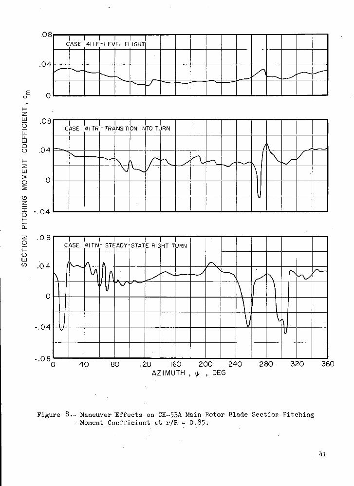
.08b 4^
1CASE 41 LF- LEVEL FLIGHT
b -^
.' o -&
1CASE
\
4ITR -TRANSITI
v^~\ /
DN IK
\W.
TOTL
;r
IRN
"\ X^t^ /"— — **•
I
\
\^s~
_x"
^
'•••— <*
. o oo
. b
I I 'CASE 41 TN- STEADY-STATE RIGHT TURN
/^-*.
o
i O J>
- .Oi0 40 80 120 160 200 240 280 320 360
AZIMUTH , <// , DEG
Figure 8.- Maneuver Effects on CH-53A Main Rotor Blade Section Pitching- Moment Coefficient at r/R = 0.85.
ftl

16000-
8000
0
16000
8 000
bJ
o -80005 2400O
o
§ 16000
o0
8 000
0
-8000
-16 000
2400
1600
800~s'
CASEI
/~"
41 L
JV
V
V
F-LEVEL FLIGHT1 1 1 1
-v^s /-"rx.^^^/-^^^— <*
1600
800
0
-800
2400
\
CASE 4ITR-TRANSITION
^S
INTO TURN
ccO
occ
1600
800
-800
\L
CASE 41 TN-STEADY-STATE RIGHT TURN
-1600
\L
\^\\
0 40 80 120 160 200 240 280 320AZIMUTH, * ,DEG
360
Figure. 9..- Maneuver Effects on CH-53A Root Torsional Moment,
k2

. 1°oUlo:Q o
-p•a•H
CVJ
0)COoj
7
oVi
(U-p
05o•H
,A^O)
ITNCO
(U II-p*H 3-O-P "
CQ Ai•H fltJ OJ
O <1Hs o<H 0)O H
00
% $•H> W>
(Uc -o(SrH OPH V£>
I
O
bO•H

LTNt-
oIIKfn
0)
COCO(1)
PM
•H-P
0)
<H•HP
0}H
CO0) •
•H CMSi t-O
-P 0)CO W
•H oJW O
•P WS
irH
CM
OJIOJ 00
ISd'

oUJ
-a-
X
LPvCO
O
II
COCO0)
ai-•H-p
•in•HPi
pp
COcu •
•H CM
O•P 0)CO CO
•H 05W o
H <Joj COC"j J
•P W
OJH
00 10 j- cvj O cvj
Xjiu/N ' d v ' 3ynSS3Hd ~l\/llN3y3ddlO
CM 00
0UJ
°
IH
ITNO\
O
II
K
0)
uCOCO0)
PH
•H•P
0)b0)
<HO
CO0) •
•H C\Jh t-O-P 0)CO 01
•H OjW U
Qj^3 I-P W
s
H
0)
CVJ CD
1*6

8000m
z
4000
X
H 0zUJ
o
^ -4000
zoCO
0 -8000
oo01 -IPOOO
NG
M
OM
EN
T
SE
CT
|QN
L
OA
D|N
Q
T '
C
m
CO
EF
FIC
IEN
T
, c
n
b
b
. .
.-
r-fc>
oo
o
-p»
oo
ro
a
1 1
1 1
I 1
i i
I i
i
SE
CT
ION
P
ITC
H!
RO
OT
TO
RS
ION
AL
MO
ME
NT
, M
x ,
N
-m
CO
EF
FIC
IEN
i ro
oo
-e>
•&
co
.' .'
OO
O
O
O
O
OO
O
O
O
O
OO
O
J>
O
\
r/R
V
1
= .95
N^-^v _/
^^~-^
^"
/
^
/
n
f \A/
\J//
AJ
1 1r/R = .95
N\
"^ f\
/ S\_^~
O F
^\.
3OSS
' '
BLE VOR1
^ — • —
EX C
•— >s
ROSS
'
INGS WITH
\
r/R ...
\
^V\
/
A
4V.
Jk
\ f\\^ ' ' ^ \
\J
^
' \
\
v //
^\
V-,
D 40 80 120 160 200 240 280
/
/
/\i
320 360
AZIMUTH , ty , DEC
Figure ih.- Azimuthal Histories of Section Loading Coefficient, SectionPitching Moment Coefficient, and Root Torsional Moment forNH-3A Case 72.

oLU
ISJ
t—oII
-Po30)
£03CO
PL.
0)<H<H•HO
HPQ
to EHOJ H
•H J"
O <U-P Wco cd•H O
,d I
<!I•
UA
CO <fr CM O
dy ' 3unSS3dd nVllN3a3ddlQ
CNJi
CO ^ O
ISd'dy'3dnSS3dd 1VI1N3H3JJIQ

CO
O
II
PS
COCOOJ^1
PH
-Pfl0)
•HO
pq<Ho •^to EH
0) H•H -3-kO 0)
-P coco cd
onLTN
^! I-P W
H onOi
•H S-tN O
bO•H
CM co

UJ0
XI-
N<
LTN
o\o
II
-Pcflo&COCOCO
•a'•H
•s0)
<H<H•HP
0)Hffl
<HO •
CQ |HOJ H
O 0)-P COCO 0}•H O
rC I
•P W
HVIiN3a3JJia
H
0)
•HIV
CM 00
50

24000
16000
8000
UJ
o
oC/5
o -8000
oo^ -16000
UJ
<3
UJoo
oso^ - .12oH0.
Zgi-o
i-Ul
o5_j<zocco
OOo:
2400
1600
800
POSSIBLE VORTEXCROSSINGS (?)
WITH r/R =.75
-800 -
-160040 80 120 160 200 240
AZIMUTH , <// , DEG
280 320 360
Figure 18.- Azimuthal Histories of Section Loading Coefficient, SectionPitching Moment Coefficient, and Root Torsional JVJoment forCH-53A Case klTN.
51

AB
SO
LUT
E
PR
ES
SU
RE
, A
BS
OL
UT
E
PR
ES
SU
RE
, A
BS
OL
UT
E
PR
ES
SU
RE
, D
IFF
ER
EN
TIA
L P
RE
SS
UR
E,
p.P
SIA
p
.PS
IA
p.P
SIA
A
p.P
SI
1 ,
,
O r
o j>
c
n o
o O
O r
o -
kc
no
oO
PO
Or
o.
&c
na
oo
or
oj
>c
no
oO
O
UJoc.— » e
^EN
TIA
L
PR
ES
S
\p ,
N/m
2x|C
T4
0
4>
0
UJu.LL
AB
SO
LUT
E P
RE
SS
UR
E,
AB
SO
LU
TE
PR
ES
SU
RE
,
AB
SO
LUT
E
PR
ES
SU
RE
, D
l
p ,
N/m
2x|0
"4
p,N
/m2x
|0"1
p
,N/m
2x
|0"4
ii
i i
i i
i i
ii
ro
J>
cn
O
ro
J>
c
n o
oo
ro
j>
cn
o^—~ .
. — -
lpm
y/c =
^— '
.J
N^
. '
„-
h
.
„,
-Pco
^
n-
-—•'
*''
h
300
/"
/
^
\
N
N
\
--
I/'
-'
^- -•*•
\\\
;^/
^^
r/
—1
R = . S
--•R = .75
-H
'r-
— -.— i
~- ~
5
v _^^
— -v95—
PPEf
•«•,
1 — ^_—— _—
1
LOW ER
^L
,'
/
^1
/
^~ .
- — .
\X
^ .^ ,
N
\
^
>
V
~. LC
\
V.
^
)WER
^UP
"~
3ER
•^^
^CUPPER
LOWER"
!
_-
— -
"~~ —
^Z
^_
'?»x^~
V^~
^ 75M.8EM.95
.''r
f
,90°
,90°,90 =
B7
73
79-
s-~~" '
r/R=75y/c=.300
^
,
,
• , -v.. . - ,
L— -•"""
^X~
\s~±
^s
r/R = .85y/c= . 3OO
S
_-^-
^- — '
r/R=.95y/c=.300
^
^-~
^
'
y
^ —
-~s~*~^*-
40 80 120 160 200 240 280 320 360A Z I M U T H , iJ- , DEG
Figure 19-- Critical Mach-Number Effect on Blade Pressure Azimuthal Historiesfor NH-3A Case 72.

LUCCZ>COcoLUora-w_jQ-< .h- CL
•Z. <LUCCLJU_LL.
LJCC
CO
3<cc coo- o_
P*Z)_loCO03<
i oo
FF
ER
EN
TIA
L P
RE
SS
UR
E
Ap
,N/m
2x
lO'4
SS
UR
lO"4
RE
AB
SO
LU
TE
P
p.N
/m'x
ro
IJ'
-M75i90=.73-
Mfl5,90=-79
-M .95,90= -85-
oo,h
UPPER-
N LOWER
1-
.r/R=.75 _y/c =.300
cr>
LJCC
COCOLU <
feLJ '|_ O.Z)_loCOCO
i oo— oo
i CDceZ)CO
LU <ceto -6Q- Q.LJ "H CL .4Z)
oS -2<r
AB
SO
LU
TE
P
RE
SS
UR
E
p,N
/mEX
|0'4
AB
SO
LU
TE
PR
ES
SU
RE
N/m
'xIC
T4
"LOWER
.UPPER.
r/R=.85y/c =.300
. ro
LOWER
UPPER
_ r / R = .95 _y/R=.300
0 40 80 120 160 200 240 280 320 360 400AZIMUTH , ^ , DEG
Figure 20.- Critical Mach-Number Effect on Blade Pressure Azipiuthal Historiesfor CH-53A Case M.
53

LJQ
1008
-poo
o-ptoa•HH
§•oo0)to
•H
•dw•o
<uCO
•H
a}
0) co-d a5rt oH
o w
st•H O•P <H
f> a•H O^ -H
•-P COa f-,o oO EH
C\J
<u
Pt.
oooCO
ooo
ooo-a-
ooooo
XIAI '1N31MOIM iooy
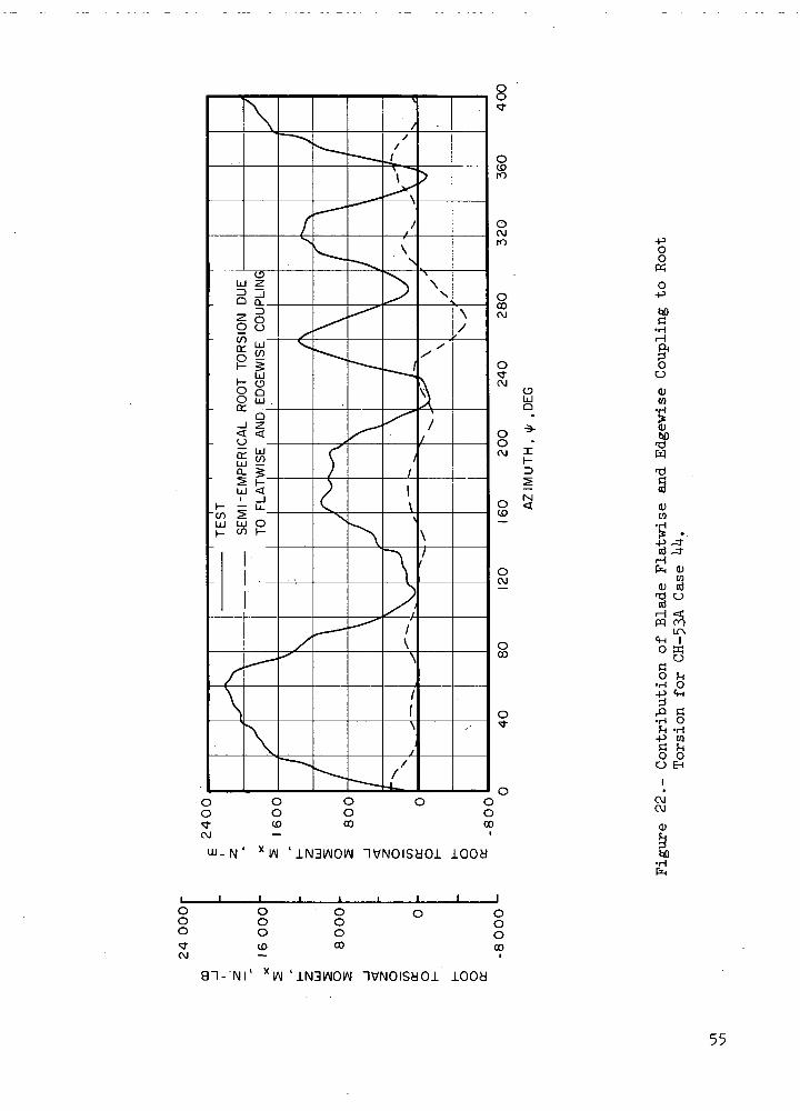
UJQ
M<
*IAI '1N3IAIOIM IVNOISHOi 1008
-POO
O•P
•HH
OO
0)CO•H
00
0)CO
05 j-HPH <Uw<D <dT) Ocd
<4H Io wcsO JH•H O-P <H
^J
^" fl•H Ofc -H
-P tQa ho oo EH
CMOJ
W)•Hfr
Ooo
OJ
ooo<0
oooco
an- NI' XIAI 'iN3iAioiAi
oooco
looa
55

1N3IA101AI DNIHOlId' *IAI ' 1N3IAIOIA1 IVNOISdOl lOOd
UJQ
Nl<
OS
O-pa]H
OCOo
aJCO
•HCO
10oo00
I I 1oo
- o
10
1 1ooo
1 1oo003
1 18o
1 1o
1 1 1
sf a
t-
CO<D oiCQ o
§<ftf^CO I0) W« &
ai oa i-to
•H -PCO fl
cd CH -Hpq a
oT* -P
CO 003 -HCD asQ) T3CU O
-P CDcu <;pq
oc -PoCO 0)
•H CO^ ccd Oft fto c5O K
onoo
' 1N3IAIOIAI 9NIH01ld OH3Va~l-"NI XIAI
' 1N31AIOIAI nVNOISdOl lOOdbO•H
56

24000K
LJ2 DO
§ -/ 16000
i -H 0 80000- x"
<rLJ< 0
32000CO
z
- 24000X
t-J5 16000
o
< 8000oCO.IT'Oi- 0
0oo:
O£VU
1-f— Z
LJS 2400
- os e| 2 1 600
— o "i—Q- 0
~" o •/ 800o: 2
— LJ
4000
Ez 3 200
_ X
^ 2400
LJ
§ 1600
z2 800CO
_ (T
°
~ s °0
- a:
-«nn
/^
r/
^^ ,\\\/ c
\V
ILCU
**^
LATI
^Vx
:D F
^v.
10 M
-\
TES"
•*v
' BL.
Sw
4DE
/^
'RES
/-
SURE
X
s
J
/
'
//
/
/
x/7/'
1
,'
</
^
x'
,
**•*
A\
\\\
^\
1
1I
\
1\
V i
/
^
i f
J
• T
DL
f^~\\\
EST
K,T 1
IE T
^>
/'
"
MODI
0 AE
V,\
:L oRO P
\
^
5CIL
ITCH
/
//
/
,'
.ATO
ING
V,'\
R RE
MOME
V\
\J
:SPO.NT ,
/
//i
MSE
c = .
\A
/
0
V/
J
'/1
iiii
40 80 120 160 200 240 280 320 360 400
AZIMUTH , y , DEG
Figure 2U.- Comparison Betveen Measured Blade Torsional Response and TorsionalOscillator Model Response to Aerodynamic Pitching Moment for CH-53ACase UU.
57

8000
4000
m71 -4000
^ -8000
i-
| -12 000o
^ 4000
800
400
a:O
ooo:
0
-4000
-8000
-12 000
O
O
8CC
-400
-800
-1200
800
400
rTEST
ANALYSIS-UNSTEADY AERO ,V. I.
ANALYSIS - STEADY AERO, V. I.
\
V
\
-400
-800
-1200
TESTI i \ 1 i I
ANALYSIS-UNSTEADY AERO/- ANALYSIS-UNSTEADY AERO, <
\
40 80 120 160 200 240 280 320 360A Z I M U T H , \lr , DEG
Figure 25— Correlation of Root Torsional Moment for NH-3A Case 72.

12000 i-
8000 -
4000 -
0 —
-40001—
5 8000
1 200
800
~ 400E
z
x .5
i -4°°5O5 i ?nn
psX,
_^
/s
x
N
w
k\
*"*•>
"N^
1 '
(
— ,
?*•
\•v
— t
—
\
FESTANALYSIS -ANALYSIS-
"X
VN\
v_^
-/
UNS'STE
"^\
'EADADY
JK-
Y AEFAERO
\/v
RO , \, V . \
/Il
1 I
^*J
Ir*\\
OITUJ
4000
-4000
Io
Q- 800Oir
400
-400
PS
_ ^_
'V_/
s
"X
\
'*~s
\\
' "" "X
\>
^ .
—
^ —
\•v.
•
—
^
• ~ i
rEST4NALiNAL
'N
r^
rsisYSIS
v__x
-UNS-UNS
_A
TEACTEAC
r?LS
Y AE)Y AE
^*C
:RO ,:RO ,
/h'
V.I.C.I.
/+
^.. — "
J
/
^- — '
a\
40 80 120 160 200 240 280 320 360
AZIMUTH , y , DEG
Figure 26.- Correlation of Aerodynamic Pitching Moment for NH-3A Case 72.
' 59

.08
.04
Eu
ItLJOot-zUJ5O
Io
oLJCO
-.04
-.08
.08
.04
-.04
-.08
TESTANALYSIS - UNSTEADY AERO , V. I.
ANALYSIS - STEADY AERO , V. I.
TEST
ANALYSIS-UNSTEADY AERO , V.I.
ANALYSIS-UNSTEADY AERO , C.I.
0 40 80 120 160 200 240AZIMUTH , ^ , DEG
280 320 360
(a) r/R = 0.75
Figure 27.- Correlation of Section Pitching Moment Coefficientfor NH-3A Case 72.
60

ON
P
ITC
HIN
G
MO
ME
NT
CO
EF
FIC
IEN
T ,
c m
bo
o
be
3 -P
>
00
J>
O
J>
0
HOUJen
- nd
o— V
X.^^— >
TE
Ah
Ah
^_
"ST
JALY!
JALYS
y
SIS -
;is -
^
JNST
STEA
^ — -
EADY
DY A
-~^~— •
AEF
ERO
' .
0 , V
, V. 1.
•\_x
1.
r/\
\\rs
J
\J^
"->
rJV1
/
^'---.
V
'
Ail
^^.
vX. —
TEST
ANALYS
ANALYS
s^_^
IS-L
IS-b
/ .
NSTE
NSTE
:ADY:ADY
~_» —
AERC
AER
—
) V 1
D,C .
^^
.
/X
\\_
^r\1
Vs,X
\
^\ H~\
r
^x—i
/J
^
V
^
AJt
0 40 80 120 160 200 240 280 320 360AZIMUTH , v|/ , DEG
(b) r/R = 0.85
Figure 27.- Continued.
61

oU-u_LiJOO
I-2LU
O
O2X
^-z.oI-oUJCO
.08
.04
-.04
1 b CD
TEST 'ANALYSIS-UNSTEADY AERO, V . I .ANALYSIS -STEADY AERO, V.I
fV
.08
.04
0
.04
.08C
A
1
\\rs
- TEC
- AN/
- AN
\
5 T ' ' -4LYSIS- UNSTEADY AERO,ALYSIS - UNSTEADY AERO ,
^ ^^s^~*' ^^ — «—
V 1
C.I.
-^^^^
rj \\\ — \<j(1
:A
A
f
7
r-'A^
>
) 40 80 120 160 200 240 280 320 36
(c) r/R = 0.95
Figure 27.- Concluded.
62

2.0
co
UJ
O
UJoo
5<o
oUJCO
.4
0 40 80 120 160 200 240 280 320 360
AZIMUTH , y , DEG
(a) r/R = 0.75
Figure 28.- Correlation of Section Loading Coefficient for NH-3A .Case 72.

2.0
1.6
1.2
.4
LU
O
Oooz.Q
O
zoI-o
-.4
2.0
1.6
1.2
.8
TEST
ANALYSIS-UNSTEADY AERO , V. I.
ANALYSIS-STEADY AERO , V. I
\
-.4
r
TEST
ANALYSIS -UNSTEADY AERO , V. I.
ANALYSIS -UNSTEADY AERO , C. I.
1
0 40 80 120 160 200 240 280 320 360
AZIMUTH , f , DEC
(t) r/R =0.85
Figure 28.- Continued.

1.6
1.2
co
LU 0
LJ_g -4o
1.6
TEST
ANALYSIS-UNSTEADY AERO , V.I
ANALYSIS-STEADY AERO , V.I.
^S
JL:
1.2
oLU
v> .8
.4
0
-.4
ESTANALYSIS -UNSTEADY AERO , V. I.
ANALYSIS - UNSTEADY AERO , C. I.
0 40 80 120 160 200 240 280 320 360
AZIMUTH , ^ , DEG
(c) r/R = 0.95
Figure 28.- Concluded.
65

24000
16000
8000
-8000
LU
O
< 24000
eno:o
Ootr
I600Q
8000
-8000
3£UU
2400
1600
800
^ -800
K2 -16005o
zo<£ 2400oi-t-§ 1 600cc
800
0
-800
-i finn
_y^
S
r~s
^~
J^
~»,
\
^
^^^
~^
^
' — "
/-/
^~
J^
•c-*^
\^
• ^
\^— ^~ -
,
^
-•=*-— >«^
—
•— -=
TEST
ANALYSIS -UNSTEADY AERO ,\
ANALYSIS- STEADY AERO , V.
X* *"•
S
^^
1
^
^/
^
',-*
^
J^^ r
\^
','
__/
-~^*
/ |
I.
^
TEST
ANALYSIS - UNSTEADY AERO , V
ANALYSIS -UNSTEADY AERO, C
.~>
s^-
\\
N
_. / '-*•^
r_~
\
•^ —
^j
i
.1.
/
^«^
N.
X-
«* **
^
s
-*—~*
^^
—'
^
s/
^
^
/
f
0 40 80 120 160 200 240 280 320 360 400
AZIMUTH , ^ , DEG
Figure 29.- Correlation of Root Torsional Moment for CK-53A Case UlLF.
66

o<tCM
O -
-Eg-< UJ>- <
-Q .-
5 <-CO £-
1 COI I
"co co"CO CO
CO <UJ Zh- <
I
\
og ooCO oo
0)COcdO
Iwo
0)IhO
O-P•HPM
ofn(U
cdH0)
OU
Oonuj _N • D'X^ • ONIHOlId 0«3V
1 18oCM
1 1
8oU3
1 1
OooCO
1 1 1o c
OC U3 CO
J I
8oCO
hO•Hfe
Bl-'NI ' 1N3IAIOW 9NIH01ld Od3V

Eo
bJO
OO
OJso
Xo
oLUCO
. 1 2
.08
.04
0
-.04
, 1 2
.08
.04
0
-.04
TEST
ANALYSIS - UNSTEADY AERO , V. I.
ANALYSIS-STEADY AERO , V. I.
TEST
ANALYSIS -UNSTEADY AERO , V. I.
ANALYSIS - UNSTEADY AERO , C. I.
0 40 80 120 160 200 240 280 320 360 400
AZIMUTH , i> , DEG
Figure 31.- Correlation of Section Pitching Moment Coefficient at r/R = 0.85for CH-53A Case
68

SE
CT
ION
L
OA
DIN
G
CO
EF
FIC
IEN
T ,
c
n
fc>
O
-P»
bo
r\3
CTijiO
-t>
oo
KJ
a
S
\\
X
Sx
^
k x\
Xs
~ <
\
X""- x
\
s_.
*ss,
^±5
^
*-«
• — -•
- — *
S
_
/
s~
-~^
T
A
M
-4
EST
vlALY
JALY
/'
^"
SIS-
5IS -
f
V
UNS1
STE/
•*
^
FEAD
\W /
^ v .
^
Y AE
\ERO
^^^ ^
A
V
RO ,
, v.
_^
V.I.
S*
/
x^. -
— — —
^, — >
^f
~<?
^
TE
AC
Ah
,
*" s
1ST
JALY!
JALY
>'
SIS -
SIS -
s
!/
UNS1
UNS1
•N
\
,'V
^
•EAD-
'EAD
' —
x
C AE
Y AE
-^
A\|
'0 ,
RO ,
_^
V 1
C.I .
•"•«
s
/
^=^
/~~
~>*r I
/ -
,
^
^
^
\\\\
X
0
s
x^
X
^v
0 40 80 120 160 200 240 280 320 360 400
AZIMUTH , </, , DEG
Figure 32.- Correlation of Section Loading Coefficient at r/E =0.85 forCH-53A Case UlLF.
69

CO
24000
16000
8000
0
-8000
-16000
24000
I 6000
2400
1600
800
trO
5 8OOOocc
-8000
-16000
- -800
-1600
2400
TESTANALYSIS -UNSTEADY AERO , V. I
—| 1— ANALYSIS - STEADY AERO , V.I .
gCOcc 1600
oocc 800
-800
-1600
ANALYSIS-UNSTEADY AERO , V. I .
ANALYSIS-UNSTEADY AERO , C.I
0 40 80 120 160 200 240 280 320 360AZIMUTH , <// , DEG
Figure 33.- Correlation of Root Torsional Moment for CH-53A Case UlTN.
70

24000
16000
8000
Q_
O
-8000
-16000
24000
16000
8000
-8000
-16000
2400
1600
800
0
o -800
-1 600
o 2400z
oCL 1600oCELU
61 800
LA
7T
TEST_| I |
ANALYSIS -UNSTEADY AERO , V. I.
ANALYSIS -STEADY AERO , V.I.
r
-800
-1600
t—/-
I I r iTEST
ANALYSIS-UNSTEADY AERO , V. I.
ANALYSIS -UNSTEADY AERO, C.I.
0 40 80 120 160 200 240 280 320 360AZIMUTH , i// , DEG
Figure 3^.'- Correlation of Aerodynamic Pitching Moment for CH-53A Case UlTN.
71

Eo
UJ
o
LUO
.08
.04
0
-.04
-.08
ANALYSIS - UNSTEADY AERO , V. I.
ANALYSIS - STEADY AERO , V. I.
O
CDZ
IO
O
oLUCO
ANALYSIS -UNSTEADY AERO , V.
ANALYSIS-UNSTEADY AERO , C. II
40 80 120 160 200 240 280
AZIMUTH , «// , DEG
320 360
Figure 35.- Correlation of Section Pitching Moment Coefficient at r/R = 0.85for CH-53A Case Ul TN.
72

co
O
1.6
1 . 2
.8
.4
uj 0oo
TEST , I I
ANALYSIS - UNSTEADY AERO , V. I.
ANALYSIS -STEADY AERO , V. I. -
<
O
OLJ
1 . 2
.8
.4
TEST.
ANALYSIS -UNSTEADY AERO , V. I.
ANALYSIS-UNSTEADY AERO , C. I.-
L
0 40 80 120 160 200 240 280 . 320 360AZIMUTH , ^ , DEG
Figure 36.- Correlation of Section Loading Coefficient at r/R = 0.85 forCH-53A Case UlTN.
73

24000
16000
8000
-8000
-16000
24000
16000
2400
1600
800
- -800
-1600
TESTANALYSIS-UNSTEADY AERO , V. I.
ANALYSIS-STEADY AERO , V.I.
cr.o
5 8000oen
-8000
-I6000L
LU
O
<zo
oocr.
2400
1600
800
-800
-1600
TESTANALYSIS - UNSTEADY AERO , V. I.ANALYSIS - UNSTEADY AERO , C.I.
80 120 160 200 240AZIMUTH , <J/ , DEG
280 320 360 400
Figure 37-- Correlation of Root Torsional Moment for CH-53A Case hk.

cc-LU
-S <-2 £
_H <_00 LU
1 fe— I 1 -
00 0000 00
•-H5 ^00 <<UJ 2 2
-H- < <-
00 sj-o
o
oII
0)•HO•H
0)oO
-PtiOJ
C•H^5O-P•H
O•H-P •O -*Q) -3-
CO<U
<H COO 0}
O
la-p LTN0) IH W<U O
O OU <tH
00ro
tt)•H
' JLN3IDIdJ30D ONIHDild NOI1D3S
75

Eo
Ld
CJ
LiJOu
.1 2
.08
.04
0
-.04
-.08
_ TEST |
ANALYSIS'-UNSTEADY AERO.V.IANALYSIS-STEADY AERO , V.I.
s
/
\y
LU.
O
OHCL
UJCO
. 1 2
.08
.04
0
-.04
-.08
- . 1 2
TEST_
ANALYSIS-UNSTEADY A E R O , V.I.
ANALYSIS-UNSTEADY AERO , C.I . -
7
0 40 80 120 160 200 240 280 320 360 400
AZIMUTH , <|/ , DEG
Figure 39.- Correlation of Section Pitching Moment Coefficient at r/R = 0.95for CH-53A Case MK
76

co
OO
E 1.6
oLJCO
ANALYSIS-UNSTEADY AERO , V. I.
ANALYSIS - STEADY AERO , V. I.
1.2
-.4
TEST
ANALYSIS -UNSTEADY AERO , V. I.
ANALYSIS-UNSTEADY AERO, C. I..
7A \
VJ
0 40 80 120 160 200 240 280 320 360 400
AZIMUTH , ty , DEC
Figure kO.- Correlation of Section Loading Coefficient at r/R = 0 . 7 5 forCH-53A Case kk.
11

UJ
O
UJOO
1.6
1.2
.8
.4
0
-.4
^\\
TF_ AK
\\
\
\
N
j1
AF\
\V1:
i 1ST
ALYSIS- UNSTEADY AERO,ALYSIS- STEADY AERO.V.
_-:^=>
'^-
"^
-•^y^F/
\ / . \ .1.
X.J,
S
f/I'//
s//
-4L/^
^
— — ^/— v
%L
^*-v\
Sv,
\\>
X
\\\\
£ 1.6Q<O
oUJtn
.4
0
\
-\
1TC
Ah
A 1
l\\ x
\V
A\\\
\\
<N.
ST
MLY
MAL^i
---
s
sis-'SIS
-**•
^
UNS
UN$
-S"
>TEA
5TEA
/-'/
DY >
DY
^-s
-•ry
1(\ERO,V.I
^ERO.C.I
y/
£- — •** "
//
/
^c_
- 17
/
Ai
/ // // /s
~N
//r-// ^
\Vv
— -^
.
<\
V\
1
k''\
~/<rv.f <*
- .\
N\\
X
\\\\\\\
^
N
0 40 80 120 160 200 240 280 320 360 400AZIMUTH , «// ,DEG
Figure 1+1.- Correlation of Section Loading Coefficient at r/R = 0.95 forCH-53A Case 1+1+.
78
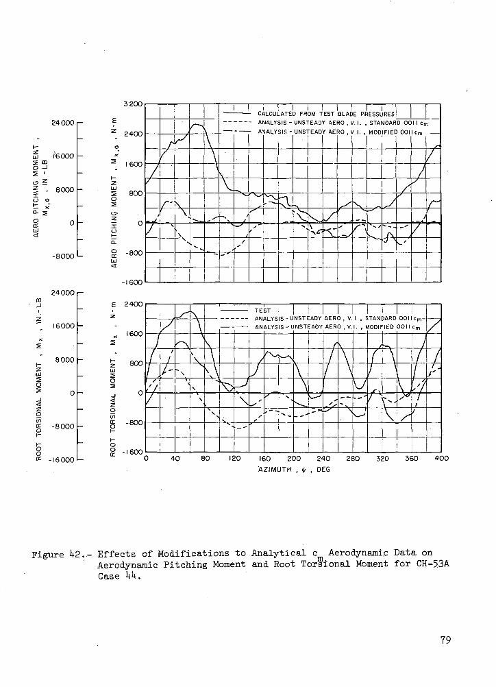
240CXD
(6000O -iS '
? - 8000O ot *Q. 5
-8000
24000
16000
8000I-zUl
I
Icng -8000
OO
-16000
3200
2400
1600
800O
xO
g -800UJ
-1600
E 2400
z
x I60°2
t 800
<zo
g -800
o2 -1600
//
/r/
/
r/
f\
X
\\.s
N
r^
"** —
* x.
\\ \V
-^x\
—
— v
/— X"
//
s
- A
- Af
'r\^s
s^
sf
M.CU
YALY
>1ALY
^
.ATE
SIS -
SIS -
r•
) FR
UNS1
UNS
"V
X•V
DM TrEAD
HEAD
^
EST
r AEY AE
S-\
BLAD
RO ,\
30 , V
^
S
E PR
'• 1- .M. ,
N•*v
/^
ESSL
STA
MOO
*^^
^
RES
MOAR
IFIE:
y
rvJ s
D OC
) 001
/s
^'
II cn
<=m
//
i
7
n
s~
/
r
)1/
•'//
//
/
^
s*
^~\
"•\
>
\\\\\N
\
\
\
\\\
•n
XN
\>
X
—
<J
\
-'
TEST
ANALYS
ANALYS
/
J
~s
ss
r\y
/"
''"
1S- UNSTEADY
S- UNSTEADY
X
•N. ^
\
\
^--'
^^ X
1AERO , V.
AERO , \l.
r//,'s^s
\\\~ V\
11. , STAN
1. , MODIF
vy• — •'
/{i£• *
) '
WRDIED
•— >,
A^
r-V
0010011
\<^
s
Cm-
Cm
1//
'-;Iii
7
//,*'
40 80 120 160 200 240 280 320 360 400
AZIMUTH , <f> , DF.G
Figure k2..- Effects of Modifications to Analytical c Aerodynamic Data onAerodynamic Pitching Moment and Root Torsional Moment for CH^Case UU.
19

o• —
RO
DY
NA
IM
OM
EN
T i= 0
I ro
yIO
NA
L IN
ER
NT
RIB
UT
ION
SO
R C
l ro
M2
O
o\ h-
UJCOLl_
Q. Li_Q- O<_lLl_
Oz
NA
L M
OD
AL
TO
RS
IO RE
-2
/t
s*^v<s : i» "*>
^^
3 TE
EXA
^_,
RM
:T
"fc^*^*.
APR
r >
=(0X1
!>
MAT
"
ON
"•</
i+;
/
+ 3
s, ^0 40 80 120 160 200 240 280 320 360
AZIMUTH , <// , DEG
Figure 1*3..- Major Analytical Contributions to Kondimensi.onal Blade Torsl.onalResponse for CH-53A Case UU With Unsteady Aerodynamics, VariableInflow, and Modified c Data.m
.80

AXIS OFHUB ROTATION
LAG-FLAPHINGE POINT
X ,Y,Z NON-ROTATING HUB AXES
x*,y*,z* ROTATING HUB AXES
x , y , z ROTATING BLADE AXES
Figure UH.- Rotor and Blade Axis Systems.
81

NOTE = COMPLETE DEFINITIONS OF THESYMBOLIC TERMS ( Y ' s ) AREGIVEN IN TABLE H.
180'
270°
FyT5,MT (APPROXIMATE)
Figure b5.- Comparison of Approximate and Exact Calculations of the FifthHarmonic of Edgevise Hinge Force, CH-53A, V ='78.U m/sec
(152.U kn), y = 0.36, fr = 0.055.
82

-
11
[{—l _^
[
'
ri_i
I]
1-0
1 UJ
Iuin
Xu.
^~~-
1
1 1
UJ1-
SXocc0.Q.
2I—
2
Oin
xLJL
\^
I
(0
U>(D
GB
tO
10
CM>•t
. 2U> Q-
>• UJ1 1^
1
CB
f5 °
>- 2
<
5 z<o >-
5 orCM O> -3
<
* S
U(D
IOX
Uto
X
u
roX
u
X
D O O O O O O3 0 o o o oD O O 0 O O*J — — CM to <3"
N ' D S 'xd 01 NOiinaiaiNOo
i i i i i io o o o o o oo o o o o o•* CM CM <? ID CO
N O ..._ z O
co <O
£ UJH
IT < -0 W5 UJo o-
UlI-o
ce —cc u,
a: ± o iu± < i- o o
UJi-<2Xos.0.
2-
(0
m
X
L_
1
1_ 1
2 fUJ [
" Eu.
X1 1
1
11
1 1 1 I I
U
U)K
*~
u
r^ ^L. ^• oro LU
'T o« 2
s" i_» o
x cro
in ^
n
X
D O O O O O O3 O O O O OD O O O O O0 in •$• ro c\J —
^j 01 NounaiaiNOO
OO<a-
0oCM
ooo
ooCO
ooID
oosf
ooCM
o
voooon3.'
onffi
w
0)
o•H
0)o
an ' 3S 'xd 01
aJfl•H
-p•Hto
>Q) OOP5 -
~-s. O
M °0 II
•*~301 EHS O | D
I
bO•HPm
an ' ss'xj 01
83

CD 400
o 200in
DO
0
-200
-400
-600
8 -600
z.Uin
LL
O1-
O
1-=>CO
CEt-
oo
C.\JW
1000
-1000
-2000
-3000
.annn
-
n n.U
1— _J
—
/- F Y,5c
~1*- F Y . S C . M T
-XI4s X I 6 $ X36s YI 4 c Y2 4 c Y I 6 c Y26c Y76c
MAJOR DYNAMIC TERM
03 600
„ 400to
200
0
Op -200rsmS -400l-zg -600
3000
2000
1000
0
| -|00°QL
oo-2000
-3000
' ,5s
n nY , 5 s , M T
n „U
n
X I 4 c X34c -XI 6 c -X36c Y I 4 s Y2 4 s Y64s Y74 s Y I 6 s Y76s
MAJOR DYNAMIC TERM
Figure ^.- Major b/Rev Lateral Hub Force Dynamic Terms, NH-3A, y = 0,36,Cm— = o.oks.a
8U

001
uin
IMU.
OH
Z
L_r^
00
o:I—
0o
1 UUU200 1-
100
0
-100
-200
-300
-400
z
500UIf)
oo
*~ - 500zo
- (-r> -1000CO
tr.~ i—
z -1500o
_ o
9nnr>
—
i-i- nL u U
r F 7 Kr
n
^ - F Z . S C . M T
ZI5c Z25 c Z35c Z45c Z55c Z65(.
M A J O R D Y N A M I C T E R M
co 200
-yj ' VW
tO
N 0
O'- -100zoj= -2001
00
£ -300zo0 -400
1 \JU\J
Z
500<oin
N 0U- w
o- 500
0— i—
— » i nnn^J — r U\JUmQL
~~ ^
§ -1500_ o
-onnn
_ ___
n-
_/~ FZ,5s/
F Z , 5 s , M T
Z45$ Z55s Z65g
MAJOR DYNAMIC TERM
Figure. 1*8.- Major b/Rev Vertical Hub Force Dynamic Terms, NH-3A, y = 0.36,
85

600
CD-i 400
w 200X
U-
H
z -200o
=> -400CD
EC.H -600Q
o-800
5 600
« 400ID
~
^ 200o
zo
3CO
E -400zg -600
ouuu
z 2000
w 1 000X
u.- o 0
h-
o -1000h-
_ ID
5 -2000cc
_ 1-§ -30000
~
z
'w 2000~ U)
X
^ 1 000o
^_o
^ -1 000
ccz -2000o
L o
_
-
I~~| I~l r-, i— i r-i- , _ , , _ , |j . - LJ.
r F x , 6 c
- LJF X , 6 c , M T
XI5c X35c XI7c X27 c X37c YI5s Y25 s Y65s Y75s Y85 s -YI7, -Y27 s -Y67s -Y77 s
MAJOR DYNAMIC TERM
_
-
n rn m n^ LJ - u u u ^ r'x...
,._h X , 6 8 , M T
X I 5 8 X35s XI 7 s X2 7 8 X37s -YI 5 c -Y25c -Y65c -Y75c Y27 c Y67c Y77c
MAJOR DYNAMIC TERM
FigureA9. - Major "b/Rev Longitudinal Hub Force Dynamic Terms, CH-53A, y = 0.36,Cm
: ~ = 0.055-
86

lOOOi-
-1 800 -
«L 600 -
o 400-
0 20° "
1 °"o:£ -200 -oo
-40QL
oto>-
u_
ot-
oKIDmccj —z0o
ouuu
4000
3000
2000
1000
-innn
/~ F Y.6c
F Y , 6 c , M T
-
-
r-, l~l l~l n n n _ r-i ni— ' LJ
-XI58 -X35s XI78 X37 8 YI5c Y25c Y65c Y75c YI7c Y2 7 c Y67c
MAJOR DYNAMIC TERM
03 400 p
» 200 -u>
/ 0-oH -200 -zoH -400 -IDmir -600 -
8 -800
» I 000 -
z -1000k io
| -2000o:
oo
-3000 -
X I 5c
U
Y,6s , MT
Y85s V17s Y27, Y6 7s
MAJOR DYNAMIC TERM
Figure 50.- Major b/Rev Lateral Hub Force Dynamic Terms, CH-53A, v = 0.36,CT— = 0.055.

CO
o(D
150
100
50
IDm^ -50
oo
-100
NLL.
800
600
400
200
CO~ -200
Oo -400
,6c ,MT
ZI6c Z36c Z56c Z66c
MAJOR DYNAMIC TERM
50CO
in<O
-50ot-
o -100
ma: -150
oo
-200
(D
i-uCO
0o
-200
-400
-600
-800
-1000
nU
-
— •
m
/ TF Z,6s
\ F Z,6s ,MT
Z16s Z36s Z56s Z66s
MAJOR DYNAMIC TERM
Figure 51-- Major b/Rev Vertical Hub Force Dynamic Terms, CH.W?3A, y = 0.36Cm
-= 0.055.
88

o
§ *°11 * *"
LJO
X * '"-
£ BS pQ3
< "^
O H
O §
< 0^ <
fe fccc
0 -. 2 4 6 8
HARMONIC ORDER , n
Figure 52— Comparison of NH-3A and CH-53A Harmonics of Radial Hinge Force
89

O* -
M
o
LJO
LJO
LJIf)
LJO LJO 0LJ a:
0
LJ y - i
Q. <S O
o2tr
£>
LL. CDO
a:
0
0
. = 0.1NH-3A
" CH-53A"
2 4 6
HARMONIC ORDER , n
8
Figure 53.- Comparison of NH-3A and CH-53A Harmonics of Edgewise Hinge Force,
90

og*°-Li- M
<
O
UJ K.> OL. "-o LJUJ WQ 10 X
O LJ
Z >
isO
o
<cr
2 4 6
HARMONIC ORDER , n
Figure '5k.- Comparison of NH-3A and CH-53A Harmonics of Vertical Hinge Force.
NASA-Langley, 1973 1 CR-2225 91

NATIONAL AERONAUTICS AND SPACE ADMINISTRATION
WASHINGTON. D.C. 2O546
OFFICIAL BUSINESS
PENALTY FOR PRIVATE USE $3OO SPECIAL FOURTH-CLASS RATEBOOK
POSTAGE AND FEES PAIDNATIONAL AERONAUTICS AND
SPACE ADMINISTRATION451
POSTMASTER : If Undeliverable (Section 158Postal Manual) Do Not Return
"The aeronautical and space activities of the United States shall beconducted so as to contribute . . . to the expansion of human knowl-edge of phenomena in the atmosphere and space. The Administrationshall provide for the widest practicable and appropriate disseminationof information concerning its activities and the results thereof."
—NATIONAL AERONAUTICS AND SPACE ACT OF 1958
NASA SCIENTIFIC AND TECHNICAL PUBLICATIONSTECHNICAL REPORTS: Scientific andtechnical information considered important,complete, and a lasting contribution to existingknowledge.
TECHNICAL NOTES: Information less broadin scope but nevertheless of importance as acontribution to existing knowledge.
TECHNICAL MEMORANDUMS:Information receiving limited distributionbecause of preliminary data, security classifica-tion, or other reasons. Also includes conferenceproceedings with either limited or unlimiteddistribution.
CONTRACTOR REPORTS: Scientific andtechnical information generated under a NASAcontract or grant and considered an importantcontribution to existing knowledge.
TECHNICAL TRANSLATIONS: Informationpublished in a foreign language consideredto merit NASA distribution in English.
SPECIAL PUBLICATIONS: Informationderived from or of value to NASA activities.Publications include final reports of majorprojects, monographs, data compilations,handbooks, sourcebooks, and specialbibliographies.
TECHNOLOGY UTILIZATIONPUBLICATIONS: Information on technologyused by NASA that may be of particularinterest in commercial and other non-aerospaceapplications. Publications include Tech Briefs,Technology Utilization Reports andTechnology Surveys.
Details on fhe availability of fhese publications may be obtained from:
SCIENTIFIC AND TECHNICAL INFORMATION OFFICE
NATIONAL A E R O N A U T I C S A N D S P A C E ADMIN ISTRAT IONWashington, D.C. 20546