Embed Size (px)
Citation preview
Pergamon PII: SOO45-7949(96)002&
Conq~vm di Swucrurrs Vol. 65, No. 2. pp. 231-239, 1991
‘0 1997 Elsevier Science Ltd. All rights reserved Printed in Great Britain
ot?45-7949197 s17.m + 0.00
ANALYSIS OF STRUCTURAL GLAZING SYSTEMS
C. V. G. Vallabban?_, M. Ziilfii A9ik-j and K. KandiQ
TDepartment of Civil Engineering, Texas Tech University, Lubbock, TX, 79409, U.S.A. iDepartment of Engineering Sciences, METU, Ankara 06531, Turkey
§Department of Civil Engineering, Menofia University, Menofia, Egypt
(Receioed 28 July 1995)
Abstract-Exterior glazing has been popular in commercial buildings especially in multistory buildings; the glass panels are bonded to the exterior of the building by silicone sealants. Thus, the glazing is identified as “structural glazing”. Of all the structural glazing systems, the four sided support system is the most critcal one. As the glass panels are designed to withstand lateral wind pressures, and when the lateral deflection of the panels increases more than its thickness, the glass plates behave nonlinearly, creating very complex stress distribution in the sealants. The sealants are subjected to normal, shear and moment forces on the edges, and a mathematical model is developed to compute the stresses in the sealants. 0 1997 Elsevier Science Ltd.
NOTATION
matrices representing the eqns (2), respect- ively
the flexural rigidity of the glass plate
the modulus of elasticity of the glass plate the nodal values of the right-hand-side of the eqns (2) for w the nodal values of the right-hand-side of the eqns (2) for u, u spring constant representing the behavior of thle silicone sealants in the horizontal, vertical and moment restraints along the edges of the plate, respectively the bending moment resultants per unit length the membrane stress resultants per unit length denotes the total number of nodes used in the fmite difference model the a.pplied distributed pressure per unit area of the plate thickness of the plate the value of the in-plane displacement of the plate at the node j at the ith iteration in tb: x-direction bending strain energy in the plate membrane strain energy in the plate the strain energy in the springs in-plane dispIacement of a generic point in the middle surface of the plate the work potential of the external loads the value of the in-plane displacement of the plate at the node j at the ith iteration in the y-direction in-plane displacement of a generic point in the middle surface of the plate maximum non-dimensional displacement in the plate maximum displacement in the plate
w
W
vertical displacement of a generic point in the middle surface of the plate the value of the lateral displacement of the plate at the node j at the ith iteration parameter for convergence the membrane strains in x, 1’ and z-directions Poisson’s ratio of the glass plate rotation about x-axis
8, rotation about y-axis
INTRODUCTION
Structural glazing has become a popular method of finishing building exteriors, especially multistory buildings. The technique consists of fastening glass, stone or other materials to the building frame using silicone sealants. Thus the sealants become an integral part of the structural glazing, and they are identified as structural sealants. Since the sealants bond the glass or stone to the frame, the external loads such as from hurricanes, earthquakes, etc., that may act on the building, are transferred from the building panels to the building frame through the sealants and vice versa. Some architects prefer to utilize panels with four-sided sealant supports, while some others use a two-sided support design. The most critical of the structural glazing systems that requires close analysis is the four-sided sealant support system. The objective of this paper is to develop a mathematical model for the analysis of the four-sided structural glazing system as it is subjected to a uniform lateral pressure that can happen during a wind storm. Here, the glass plate and the structural sealants interact together in such a way that the distribution of the forces in the sealants is dependent on the behavior of the glass plate and vice versa; in other words, the analysis of a structural glazing system is a glass-sealant interaction problem.
231

232 C. V. G. Vallabhan et al.
It is known that the window glass plates, being classified as thin plates, behave nonlinearly when subjected to lateral pressures; and the problem to be analyzed becomes a geometrically nonlinear one. The work of the previous investigators who calculated the stresses in the sealants with gross simplifications are given below. Here, a complete displacement formu- lation of the nonlinear analysis of the thin plate is made, assuming the material behavior of the sealants is assumed to be linear. Three nonlinear differential equations are derived for the mathematical model, and these equations are solved using the well-known finite difference method along with an iterative procedure. A typical problem is chosen as an example, where the different restraining aspects of the sealants are individually studied for various values of the sealant properties. This way, engineers can determine the effect of the material properties of the sealants on the behavior of the glass or stone plates, such that more rational and economic design procedures can be developed in future.
THE MATHEMATICAL MODEL
A simplified analysis of the forces in the sealants in structural glazing systems has been done by Vallabhan et al. [l, 21 using the von Karman theory of plates with Airy stress function to represent the membrane behavior. They represented the behavior of the silicone sealants as linear and nonlinear springs continuously placed on the boundary perpendicular to the plane of the plate. In other words, they ignored the in-plane and moment resistance of the silicone sealants on the edges. Often, designers questioned the restraining effects of the sealants on their stress distributions, but there were no models available to calculate them. With the Airy stress function formulation, the restraints of the sealants in the in-plane of the plate are hard to incorporate into the von Karman equations; hence a complete displace- ment formulation of the nonlinear behavior of the plate was found to be necessary in this case. The mathematical model developed here is very similar to
a) Glass with sealant support
Glass Plates
Spacer
IG Seal
C) Idealization used in the present model
Fig. I. (a) Glass with sealant support. (b) Detail for section X. (c) Idealization used in the present model.
Analysis of structural glazing systems
Silicone Sealant
w S
(a) Underformed State
w - disp.
(b) Derfomed State
233
(c) Idealization of Elastic Sealant Support
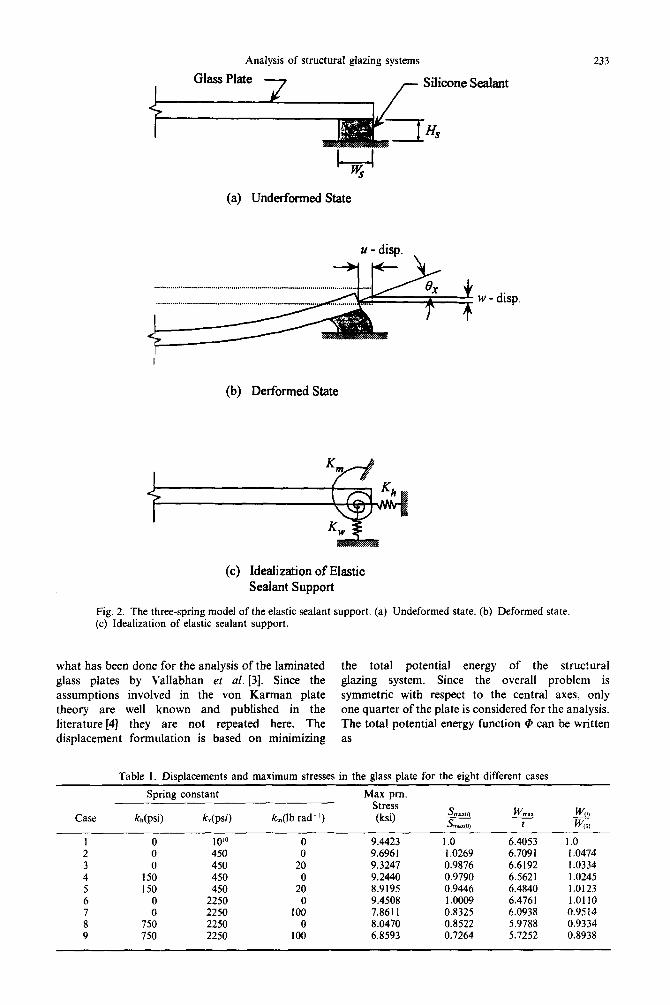
Fig. 2. The three-spring model of the elastic sealant support. (a) Undeformed state. (b) Deformed state (c) Idealization of elastic sealant support.
what has been done for the analysis of the laminated the total potential energy of the structural glass plates by Vallabhan et al. [3]. Since the glazing system. Since the overall problem is assumptions involved in the von Karman plate symmetric with respect to the central axes, only theory are well known and published in the one quarter of the plate is considered for the analysis. literature [4] they are not repeated here. The The total potential energy function @ can be written displacement formulation is based on minimizing as
Table I. Displacements and maximum stresses in the glass plate for the eight different cases
Case
Spring constant
kh(psi) k,(psi) k,(lb rad-‘)
Max pm. Stress (ksi)
0 0
0 150 150
0
75: 750
10’0 0 9.4423 1.0 6.4053 1.0 450 0 9.6961 1.026Y 6.7091 1.0474 450 20 9.3247 0.9876 6.6192 1.0334 450 0 9.2440 0.9790 6.5621 1.0245 450 20 8.9195 0.9446 6.4840 1.0123
2250 0 9.4508 1.0009 6.4761 1.01 IO 2250 100 7.8611 0.8325 6.0938 0.9514 2250 0 8.0470 0.8522 5.9788 0.9334 2250 100 6.8593 0.7264 5.7252 0.8938

234
8.0
C. V. G. Vallabhan et al.
7.0 - simply supportad
-- co88 4
6.0 - -.- core 6
6.0 -
4.0 -
0.0 0.1 A&L pr=Err. 0.4 0.6 0.6 0.7 psi
Fig. 3. Variation of central displacement with pressure.
where @ = Ub + um + us + v
Ub = bending strain energy in the plate,
U, = membrane strain energy in the plate,
US = ;(kllu*IAc + k&C + kme.:IAC
+ k,e.%lc + k”W21ACBBC),
the strain energy in the springs that represent the silicone sealants on the edges as shown in Figs 1 and 2, and V = the work potential of the external loads. Here the coefficients khr k, and k, are the equivalent spring constants representing the behavior
(1) of the silicone sealants in the horizontal, vertical and moment restraints along the edges of the plate as illustrated in Fig. 2. Minimizing the @ function with
I I I I I
0.0 5.0 oi6WizMc,J azO[x - 30:; in
25.0 JO.0
Fig. 4. Variation of vertical forces in sealants at q = 0.64 psi.
Analysis of structural glazing systems 235
J1.s
LO
23
2.0
1.6
1.0
0.6 t e.-. co80 8
0.0 1 I I I 1 I
0.0 6.0 10.0 25.0 Distance along
a~Z’[x =
30?$; in
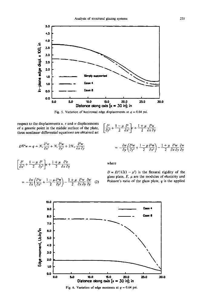
Fig. 5. Variation of horizontal edge displacements at q = 0.64 psi.
respect to the displacements u, v and w displacements of a generic point in the middle surface of the plate,
E+l-/La2 I + p ab --
three nonlinear differential equations are obtained as: aY2 2 a2 ‘+2- 1
[
bps* -g+--
2 8y’ 1
u + I + P a20 Taxay
30.0
aw ah - - = - ay ay2 + 2 ( i - p a+ I + p azw aw -- ____
ax2 > 2 axayay
where
D = _W/l2( 1 - p2) is the flexural rigidity of the
1 + P a*w aw c2J - 2 axayay
glass plate, E, p are the modulus of elasticity and Poisson’s ratio of the glass plate, q is the applied
10.0
0.0 t Core4
6.0 c -- CONI
7.0 - -----y_
6..0 -
\ so -
.
0.0 6.0
DiitonZ~“obng oZf[x - 30?$ in 26.0 30.0
Fig. 6. Variation of edge moments at q = 0.64 psi.

236 C. V. G. Vallabhan et al.
\ I P G
OO 8 I,1 IIII
5 10 15 20 25 30 Fig. 7. Distribution of maximum principal stresses (simply supported case).
distributed pressure per unit area of the plate, N,, N,. and N,,. are the membrane stress resultants per unit length. Membrane stress and bending moment resultants are expressed in terms of the internal strains and curvature of the plate as shown below:
and
I _.
OO I I I #I I III
5 10 15 20 25 30
Fig. 8. Distribution of maximum principal stresses (Case 4).
I P LF
OO , I \
5 10 15 :
Fig. 9. Distribution of maximum principal stresses (Case 8).
Here, M,, MT and M,. are the bending moment resultants per unit length, and c:‘, t:!’ and y; are the membrane strains which can be expressed in terms of the derivatives of the u, v and w displacements as shown below:
au I aw 2 e=x+2 s ( >
(4)
au au aw aw y;r=dy+ax+jyay.
In the above straindisplacement equations, the assumption of von Karman are used, where quadratic terms of the in-plane displacements are ignored. In the field equations, given by eqns (2), it can be noticed that the equations are nonlinear, and they are written in such a way that the right-hand side of the field equations are all nonlinear, while the left-hand sides contain only linear differentials. This arrangement is essential for the iterative procedure used to solve the nonlinear equations, discussed in this paper.
BOUNDARY CONDITIONS
The effect of the silicone sealants along the edges of the plate is illustrated in Fig. 2. As the plate is

Analysis of structural glazing systems 237
loaded uniformly there is symmetry with respect to X, y and z axes, and because of symmetry, the boundary conditions are shown for the quarter plate only. Referring to Fig. 2a,
On OB,
@x=0, u = 0 and yyr = 0, (5)
aMl 0, =%;= 0 and M,.= 0 (6)
and on AC
@x=0, r;.:. = 0 and N, = - k,,u (7) Kirchoff shear
= v+5?!& -k,w and &fY = -km& (8)
Similarly on OA
@y=O, v=o, aw
y; =0 and BJ =a~= 0,
M.Ty = 0 (9)
and on BC
@y = 6: y;. = 0, NY = -khv
ff+aM,.= -kvw
ax
and
MY = -k,B,.. (10)
All equations on the boundary containing the spring constants k,,, k, and k, represent elastically restraint conditions exerted by the silicone sealants. Now the three differential equations given in eqns (2) and the boundary condition:5 equations on the four sides of the quarter plate given by the set of equations in eqns (5+0-(O) become the complete set of equations that represent the mathematical model of a structural glazing system.
SOLUTION TECHNIQUE
The classical finite difference technique was employed here to solve the above nonlinear differential equations. The solution technique con- sists of keeping the linear portion of the differential equations on the left-hand-side as shown, while all the nonlinear part are kept of the right-hand-sides of the equations. Using the finite difference technique, the left-hand-side of the equations are transformed into linear algebraic equations, while the right-hand- sides are represented by values at the finite difference
nodes calculated from the previous iteration. These equations are symbolically written as
where [A] and [B] are matrices representing the eqns (2), respectively. The vectors {f;(W, U, v)} and {f2( w)} represent the nodal values of the right-hand- sides of the respective equations. The vectors {V}, {V} and {W} are the nodal values of the displacements in the middle of the plate at the finite difference nodes. Since the right-hand sides of the equations are not known a priori, values at the ith iteration are used to calculate them; the new set of equations at the (i + I)-th step become:
[A]{ w}‘+’ = {Q) + {fi@‘> 0, TP (13)
[B] (1
‘: ‘+I = {fi(w}~+’ (14)
where
q+’ = f(u:+’ + q), and
q+“’ = f(y+’ + F). (15)
The value of tl is found to be a function of the non-dimensional parameter W, = w,,,/t, for obtain- ing satisfactory convergence of the iterative pro- cedure. The value of CI has been published before by Vallabhan [5]. Fifteen to 20 divisions of the quarter plate are found to yield satisfactory results for the entire stress analysis. The lateral pressure is applied in increments so as to keep the number of iterations relatively small and, at the same time, one can obtain the intermediate behavior of the plate and the sealants. The iteration is continued until satisfactory convergence of solutions are obtained. The following equation is used to establish the convergence of the solution, which will guarantee convergence in the entire domain:
j$, II q+’ - m;ll
NW;;; < 0.0001 (16)
where N denotes the total number of nodes used in the finite difference model, and @ = the value of the lateral displacement of the plate at the nodej at the
238 C. V. G. Vallabhan et al.
ith iteration. Once a convergent solution is obtained for a particular load increment, the membrane and bending stresses are computed at each node of the finite difference mesh. The stresses are algebraically added together to obtain the maximum principal stresses in the glass plate at every node on both sides of the plate. From the boundary displacements, and the corresponding spring constants, the distribution of the three forces on the sealants is computed.
RESULTS OF AN EXAMPLE PROBLEM
The dimensions of an example structural glazing system are used as given below, since good theoretical results were available for the glass plate in the system for simply supported boundary conditions. In the beginning, this problem is solved to study the behavior of the system where each individual sealant spring constants are applied separately as well as collectively, and the results are compared to those obtained for simply supported boundary condition. Altogether eight different cases are solved, and the details of the eight different cases are given in Table 1. The dimensions and the material properties are:
size of the glass plate 2a = 2b = 60 in (152 cm)
thickness of the plate t = 0.1875 in (0.4763 cm)
modulus of elasticity of glass
E = 10’ psi(68.95 GPa)
Poisson’s ratio of glass I* = 0.22.
The properties of the sealants are varied in this analysis, as given in Table 1. For the first four cases, the value of the modulus of elasticity of the sealant is assumed as 300 psi (2.069 MPa), while for cases 5-8, the value is increased to 1500 psi (10.343 MPa). The cross section of the sealant on the edges is assumed to be uniform and is taken as 0.5 in (1.270 cm) in height and 0.75 in (1.905 cm) in width. The calculated values of the spring constants are indicated in Table 1. In this table, the values of the absolute maximum principal stress, maximum dis- placement/t ratio for the different cases are presented. Also presented are the ratios of the maximum principal stresses and displacements to those in the simply supported case. The results indicate that the size and material properties of the silicone sealants can affect the efficiency of the structural glazing systems.
The values given in the table are primarily to compare quantities that portray some qualitative behavior of the overall system. To study the distribution of the various properties in the domain of the plate, we need to examine the distribution of the displacements, principal stresses in the glass plates
and the forces in the sealants. Only two cases 4 and 8, are selected for this as these two cases contain all the boundary spring forces the represent the silicone sealants. Figure 3 indicates the variation of the maximum displacement at the center as the lateral load increases from 0 to 0.64 psi (4.413 kPa). There is virtually very little difference between the maximum displacements for case 4 and the simply supported case. In this case, the spring constants are small; however, the increase of the vertical displace- ments is counterbalanced by the restraining effects of the horizontal and moment spring constants. But, as the values of the spring constants increase, the values of the maximum displacements decrease as can be seen in case 8. Figures 4-9 are made for the system and subjected to lateral pressure q = 0.64 psi (4.413 kPa). Figure 4 illustrates the distribution of the vertical forces in the sealant for the two cases 4 and 8 and they are compared to the simply supported case. It is interesting to note that there is very little change in all these cases for the vertical distributions except at the very corner. The calculated value at the corner could also be questionable because of the assumptions of the classical plate theory. Figure 5 illustrates the variations of the in-plane edge displacements for the three cases mentioned above. The displacements are relatively the same, but the in-plane shear forces in the sealants can be different because the spring constants are substantially different; in particular the in-plane edge forces in the simply supported boundary condition are assumed to be zero. Figure 6 illustrates the distribution of the moments in the sealants along the edges of the plate. Figures 7-9 show the contours of the distribution of the maximum principal stresses in the quarter plate for a pressure q = 0.64 psi (4.413 kPa). The value of the maximum stress in the plate for case 4 is larger than for the simply supported case, whereas the value of the maximum principal stress decreases as the value of the spring constants increase. The are some positive indications that might trigger some serious research for the development of some optimum sealant design procedures so that the stresses in the glass plates may be reduced to increase the reliability of the overall system.
CONCLUSIONS
From this study, it is clearly seen that the mathematical model can be used to compute the in-plane and out-of-plane forces and equivalent moments in the sealants along the edge of the plate. It is indeed too hard to measure the displacements and forces in the sealants in practice; but the model can be used to calculate them. Research work is in progress to measure the slope of the plate along the edges and compare the values of these slopes with the theoretical results. Once the distribution of the three forces along the edges of the plates are computed, one can easily compute the maximum stress in the

Analysis of structural glazing systems 239
sealants. It is to be noted that the in-plane shear forces and the edge moments in the sealants create substantial increase in the sealant stresses, a factor which is currently neglected in practice.
Acknowledgements-The authors of this paper acknowledge the support from the National Science-Fiundation, grant no. MSM-9007911 for research on Structural Glazing Systems. The support by Dr Ken P. Chong, Program manager for the prqiect is gratefully acknowledged. The authors also acknowledge the support from Mr Larry Carbury of Dow-Corning, MI, who obtained financial supper; from various other industries such as Viracon, Owatonna. MN: Cardinal IG. Minneanolis. MN: Dakota Granite, Gilbank, SD, for supplying ihe samples for the structural glazing systems and silicone samples for this project. The authors also acknowledge the support from the Peace Fellowship Foundation for Dr Kamil Kandil to do
post doctoral research at Texas Tech University, during which time he modified the computer program for the analysis of structural glazing systems.
1.
2.
3.
4.
5.
REFERENCES
C. V. G. Vallabhan, B. Wang, D. Chou and J. E. Minor, Thin glass plates on elastic supports. AXE J. struct. Engng lll(ll), 24162426 (1985). C. V. G. Vallabhan, D. Chou and J. E. Minor, Sealant forces in structural glazing systems, ASCE J. struct. Engng 116(4), 1080-1089 (1990). C. V. G. Vallabhan, Y. C. Das, M. Magdhi, M. Asik and J. B. Bailey, Analysis of laminated glass units. AXE J. srrucr. Enpnp. 119(5). 1572-1585 (19931. --. .I.
S. Timoshenko and S. Woinowscy-Kreiger, Theory of P/ares and Shells. McGraw-Hill, New York (1959). C. V. G. Vallabhan, Iterative analysis of nonlinear glass plates. ASCE J. struct. Engng l@(2), 489-502 (1983).