Embed Size (px)
Citation preview
Andrew MossASTeC
7th December 2011
MICE RF System
Contents• High power amplifier testing
– Results so far
• Hall layout– CAD modelling– MICE Cavity at the MTA– Phase shifters– Peak power handling
• Conclusion
Andrew Moss
Amplifier status
Andrew Moss
• First medium power (250kW) amplifier and power supply system tested 2008
• Refurbishment and rebuild of first high power (2MW) amplifier complete October 2009
• Power supplies for first 2MW amp operational• Two further 300kW amplifiers awaiting repair• Two refurbished 2MW CERN amplifiers partly
tested, awaiting assembly and high power test• Still need to build 3 more sets of power supplies• One more 300kW amplifier to buy/acquire

RF system components
Andrew Moss
2 MW Amplifier
2 MW Amplifier
Master OscillatorControls etc
201 MHz Cavity Module
2 MW Amplifier
2 MW Amplifier
201 MHz Cavity Module
LBNL CERN
300 kW Amplifier
300 kW Amplifier
300 kW Amplifier
300 kW Amplifier
HT Supplies
HT Supplies
Daresbury
DL Test SystemAt present
Auxiliary Systems
Auxiliary Systems
Not found
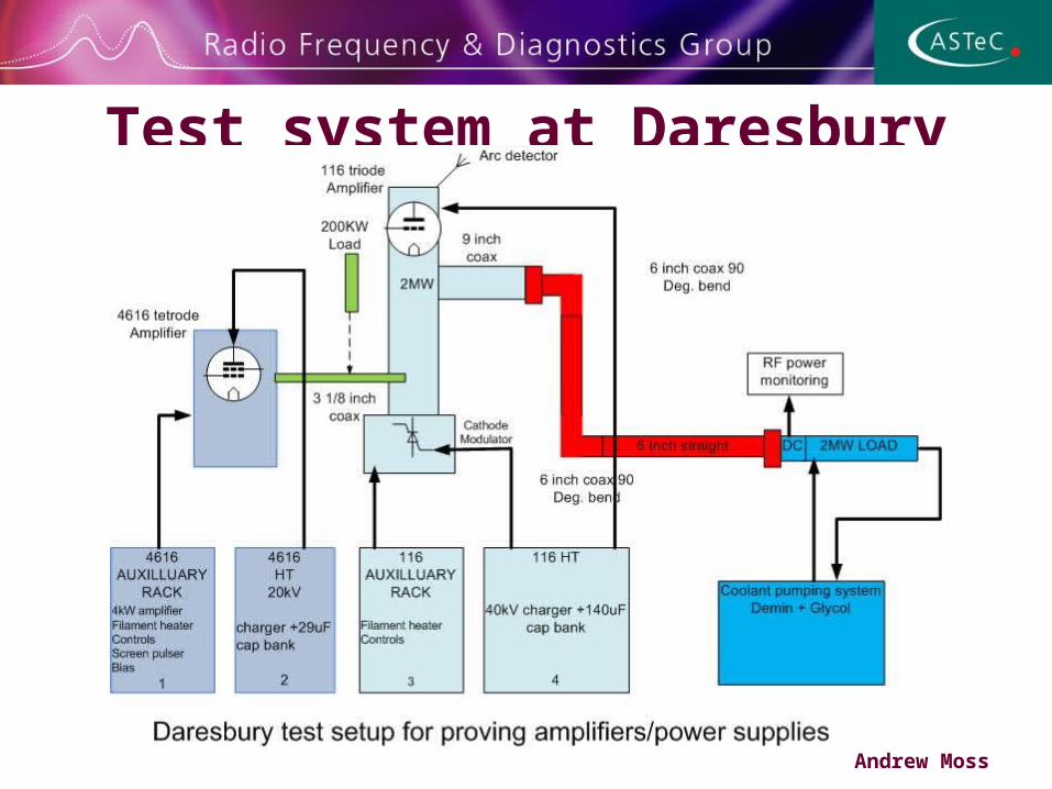
Test system at Daresbury
Andrew Moss
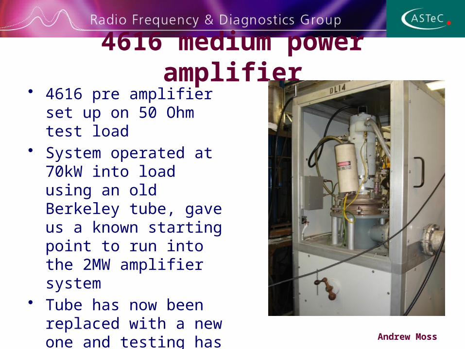
4616 medium power amplifier
• 4616 pre amplifier set up on 50 Ohm test load
• System operated at 70kW into load using an old Berkeley tube, gave us a known starting point to run into the 2MW amplifier system
• Tube has now been replaced with a new one and testing has been done up to 120kW
Andrew Moss
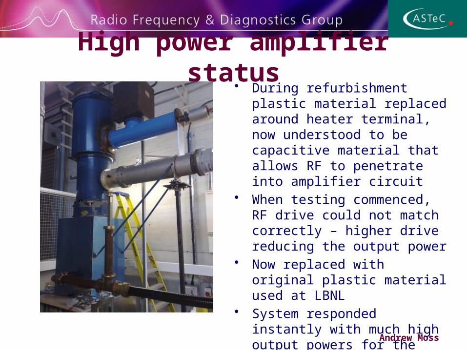
High power amplifier status
Andrew Moss
• During refurbishment plastic material replaced around heater terminal, now understood to be capacitive material that allows RF to penetrate into amplifier circuit
• When testing commenced, RF drive could not match correctly – higher drive reducing the output power
• Now replaced with original plastic material used at LBNL
• System responded instantly with much high output powers for the same drive input
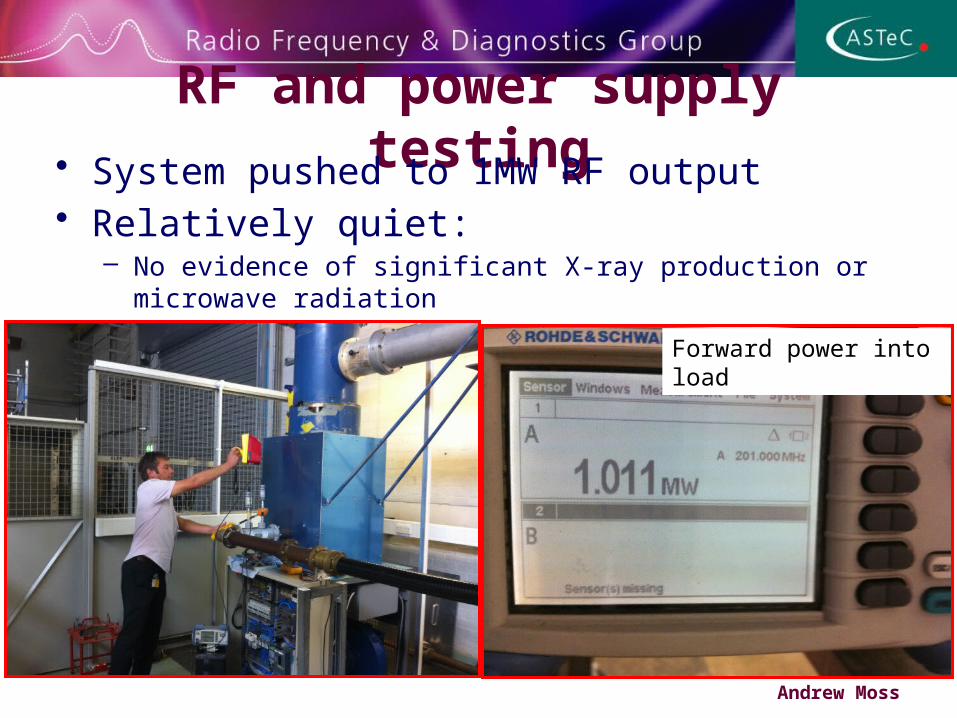
RF and power supply testing• System pushed to 1MW RF output
• Relatively quiet:– No evidence of significant X-ray production or microwave radiation
Andrew Moss
Forward power into load
Further 116 testing• Old ISIS tube showing gain of 10 which is to be
expected, has allowed test of amplifier up to 1MW• So far the amplifier system seams very well behaved
at up to 30kV and 1MW• Now plan to swap to a new 4616 and new 116 to push
system harder• New 4616 tube has proved to be more difficult to set
up, lots of oscillation, currently still investigating using test load however 120kW at 15kV with 16dB gain
Andrew Moss
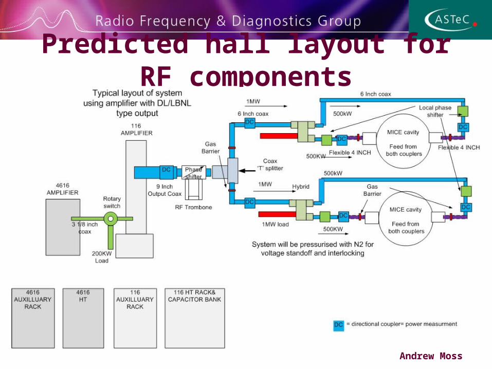
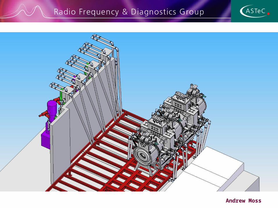
Predicted hall layout for RF components
Andrew Moss
Coax design• Hybrid power splitters to divide power before each cavity with a rejection
load, however the reject load will only see reflected power from unbalanced conditions which will be small, this load could be limited to a 50kW device, this should provide a robust reliable system
• Local phase shifters in each cavity coupler, small range available only due to physical size of phase trombones, so need to plan coax system carefully to get phase lengths within range at the cavity input couplers
• Power monitoring in each section of coax will be linked in to RF control system so that issues can be flagged before faults occur
• Nitrogen gas pressure system with the coax for voltage stand off and interlock
• Plan to have the ability to connect test loads in place of cavity to test amplifier/coax system in its complete configuration
Andrew Moss
Andrew Moss
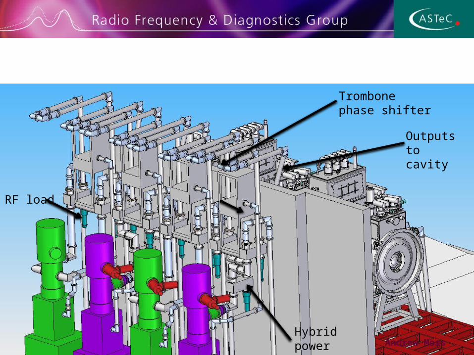
Trombone phase shifter
Hybrid power splitter
RF load
Outputs to cavity
Andrew Moss
Andrew Moss
Andrew Moss
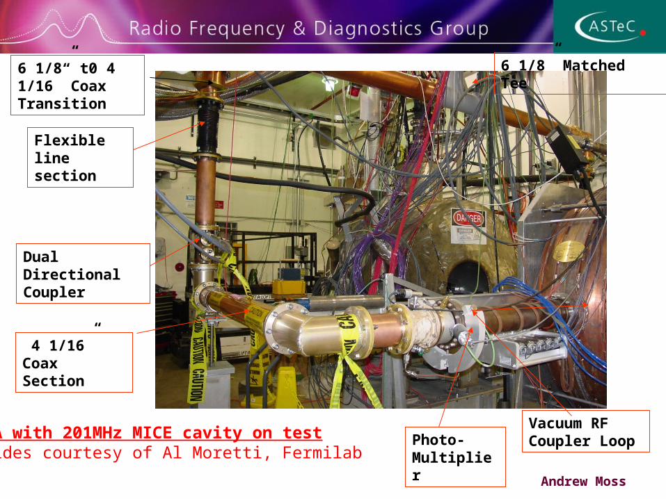
Vacuum RF Coupler LoopPhoto-
Multiplier
4 1/16” Coax Section
Flexible line section
6 1/8” t0 4 1/16” Coax Transition
6 1/8” Matched Tee
Dual Directional Coupler
MTA with 201MHz MICE cavity on testSlides courtesy of Al Moretti, Fermilab
Andrew Moss
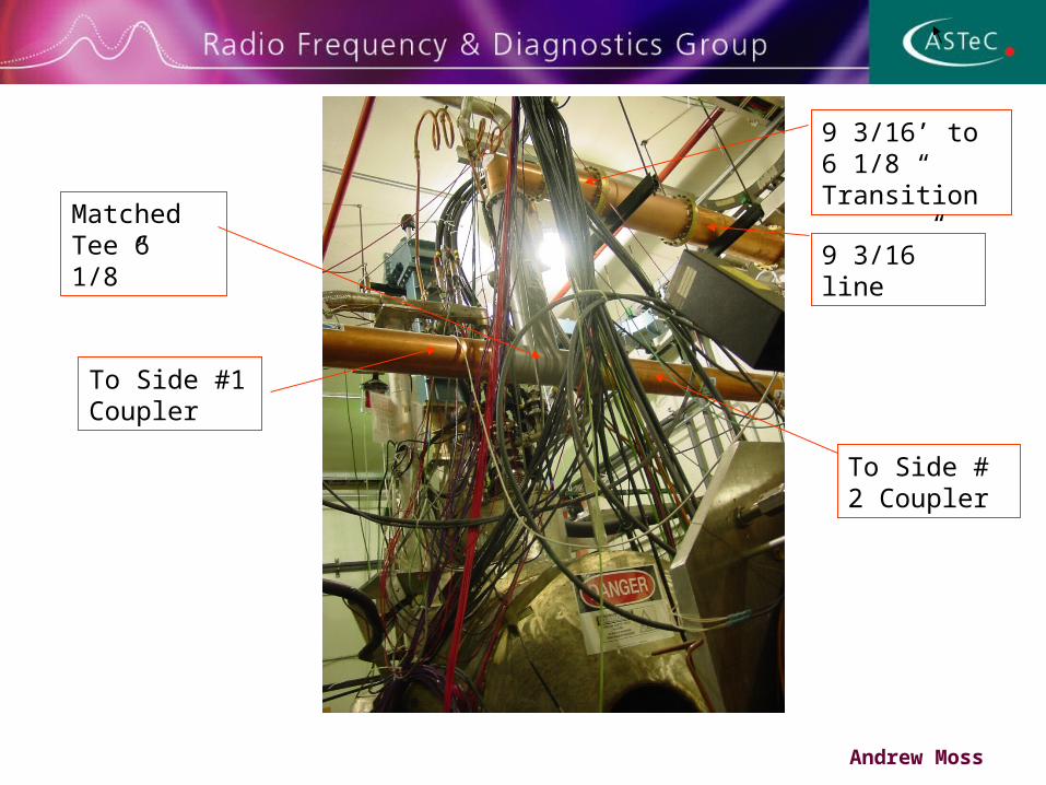
Matched Tee 6 1/8”
9 3/16’ to 6 1/8 “ Transition
To Side #1 Coupler
To Side # 2 Coupler
9 3/16” line
Andrew Moss
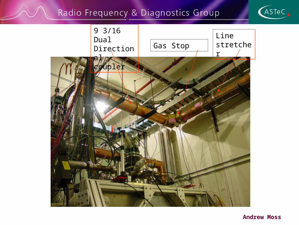
Gas Stop
9 3/16” Dual Directional coupler
Line stretcher
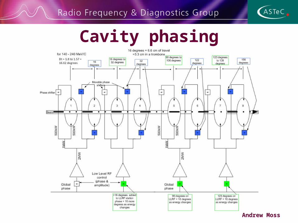
Cavity phasing
Andrew Moss
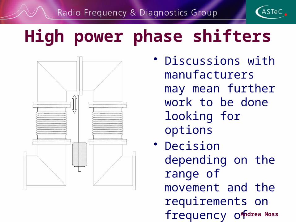
High power phase shifters• Discussions with
manufacturers may mean further work to be done looking for options
• Decision depending on the range of movement and the requirements on frequency of movement
• LLRF can be used to move drive to amplifiers very easily Andrew Moss
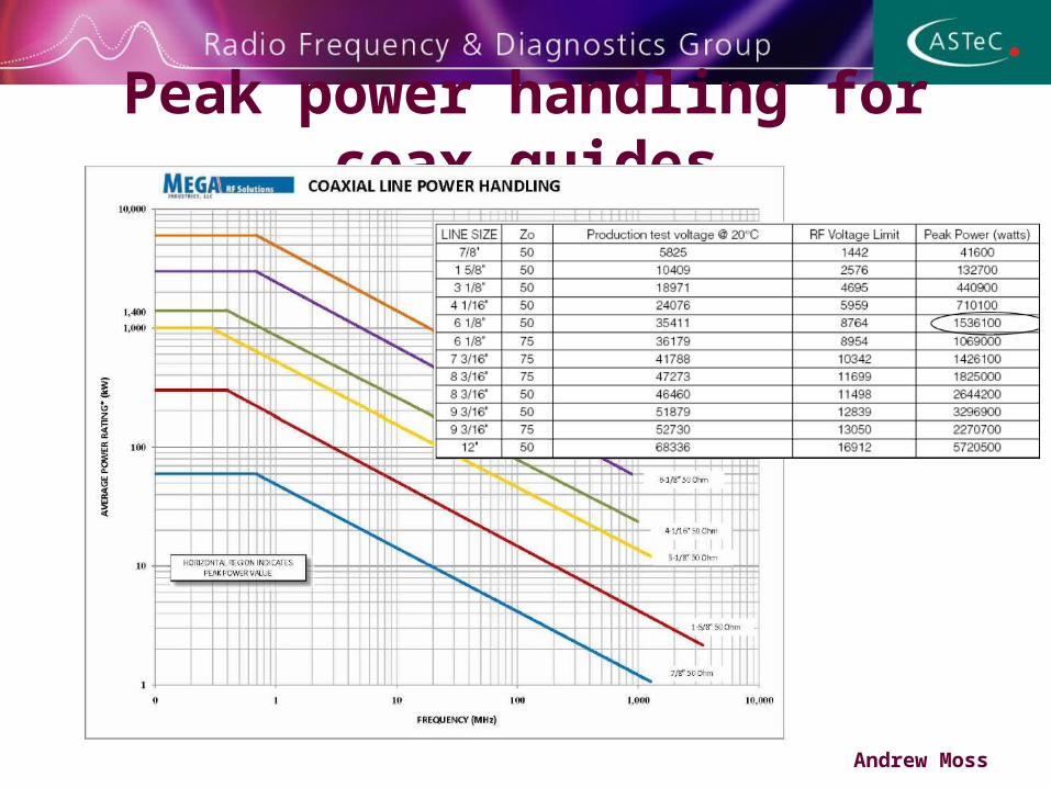
Peak power handling for coax guides
Andrew Moss
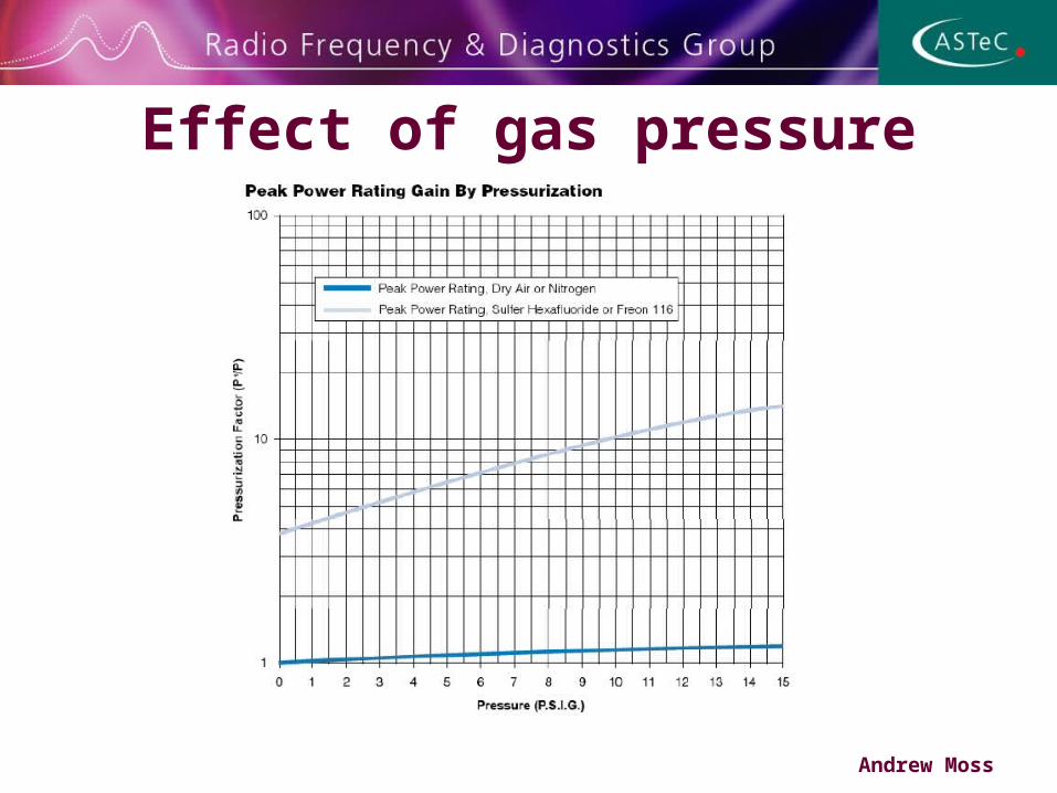
Effect of gas pressure
Andrew Moss
Conclusion• Amplifier test system tested to 1MW with power supplies• Coax system designed to phase match RF into each cavity, all
coax lines are the same length and have the same number of elbows
• Hybrids will be used to split RF power and give good isolation, reject load can be small as balanced reflected power will be directed back to triode, this should not present an issue
• Cavity phasing can be done using a combination of LLRF and limited range high power phase shifters
• Nitrogen gas pressure will be used to extend the peak voltage stand off of the coax guides
Andrew Moss