Embed Size (px)
Citation preview
Distribution Category:Energy Storage-Elec trochemical-Advanced Batteries (UC-94cb)
ANL-81-14
ARGONNE NATIONAL LABORATORY9700 South Cassr Avenue
Argonne, Illinoie 60439
CALCIUM/METAL SULFIDE BATTER DEVELOPMENT PROGRAM
Progress Report forOctober 1979-September 1980
by
D. L. Barney, M. F. Roche, S. K. Preto,L. E. Ross, N. C. Otto, and F. J. Martino
Chemical Engineering Division
D.cAh9
March 1981.
Work performed under Lawrence Berkeley Laboratory Contract No. MI 450-5310
for the Applied Battery and Ilectrochemical Research Project, Frank NcLarnom,
Manager.

TABLE OF CONTENTS
ABSTRACT . . . . . . . . . . . . . . . . . . . . . . . . . . . . . . 1
SUMMARY . . . . . . . . . . . . . . . . . . . . . . . . . . . . . . . 1
I. INTRODUCTION . . . . . . . . . . . . . . . . . . . . . . . . . 2
II. SEPARATOR CHEMISTRY . . . . . . . . . . . . . . . . . . . . . . 2
III. NEGATIVE-ELECTRODE DEVELOPMENT . . . . . . . . . . . . . . . . 3
IV. POSITIVE-ELECTRODE DEVELOPMENT . . . . . . . . . . . . . . . . 6
V. ELECTROLYTE DEVELOPMENT . . . . . . . . . . . . . . . . . . . . 7
VI. CELL DEVELOPMENT . . . . . . . . . . . . . . . . . . . . . . . 8
VII. CONCLUSIONS . . . . . . . . . . . . . . . . . . . . . . . . . . 13
ACKNOWLEDGMENTS . . . . . . . . . . . . . . . . . . . . . . . . . . . 13
REFERENCES . . . . . . . . . . . . . . . . . . . . . . . . . . . . . 14
iii
I

LIST OF FIGURES
No. Title
1. Cyclic Voltammogram for Ca-Al Ele::trode inLiCl-NaCl-CaCl2-BaCl2 Electrolyte . . . . . . . . .
2. Cyclic Voltammogram for Ca-Al-Si Electrode inLiCl-NaCl-CaCl2-BaCl2 Electrolyte . . . . . . . . .
3. Achieved Specific Capacity of Ca-Al-Si Electrodes at500 C . . . . . . . . . . . . . . . . . . . . . . . .
4. Performance of Negative Electrodes at '450 C inLiCl-NaCl-CaCl 2-BaCl 2 Electrolyte . . . . . . . . . .
5. Comparison of FeS and Fe(Co)S2 Electrode Performance
6. OperatingfHistory of Cell CA-24 . . . . . . . . . . .
7. Typical Charge and Discharge Voltage Curves forCell CA-24............... . . . . . . .
8. Electrode Polarization Characteristics for Cell CA-24
LIST OF TABLES
No. Title
1. Cell Test Su ary . . . . . . . . . . . . . . . . . . . . . .
iv
Page
4
5
5
.. . . . 6
7
. .10
11
12
Pa9e
9
. ." ." ." ."
. ." ." ." ."
. ." ." ." ."
. ." ." ." .
. ." ." ." ."

CALCIUM/METAL SULFIDE BATTERY DEVELOPMENT PROGRAM
Progress Report forOctober 1979-September 1980
by
D. L. Barney, M. F. Roche, S. K. Preto, L. E. Ross,N. C. Otto, and F. J. Martino
ABSTRACT
A Ca-Al-Si/FeS2 cell has been developed and has exhibitedreasonably stable capacity through 3200 h of operation. This sys-tem is expected to be capable of meeting the ultimate performancegoals (i.e., 160 W-h/kg) of this development program. Furthertests of this cell system in the coming year will better defineits ultimate performance capabilities.
SUMMARY
Separator Chemistry. A reaction between the Ca-Si negative electrodeand the boron-nitride (BN) separator material has limited the cycle life andperformance of calcium cells. Chemical tests showed that the reaction couldbe eliminated by preventing the formation of high-calcium-activity compoundssuch as Ca2 Si. Lower activity compounds, such as CaSi and CaAl2, did notreact with BN.
Negative-Electrode Development. A high-performance negative electrodewith a composition of CaAl 1 . 2Si0 .4 was developed in cyclic voltammetryexperiments. According to the separator chemistry tests, this alloy willnot react with BN separators.
Positive-Electrode Development. Tests of the FeS electrode indicatedacceptable utilization (652) at a current density of 40 mA/cm2. Cyclicvoltammetry tests were used to evaluate two types of carbon current collec-tors for FeS2 electrodes. A finely divided carbon (E-Coke Flour) appearedto be superior to carbon foam.
Electrolyte Development. The effects of electrolyte composition on theperformance of FeS2 electrodes were evaluated by cyclic voltametry. Varia-tions in the concentration of sodium, potassium, and barium ions had noeffect; higher calcium-ion concentrations were beneficial. A ternaryLiCl-KCl-CaF2 electrolyte for use with CaF2 powder separators was subjectedto a preliminary cell test and gave encouraging results.
Cell Development. Eight cell tests were conducted to evaluate variouspossible solutions to the problem of BN-separator degradation. TheCaAl1.2Si0.4/FeS2 cell test was highly successful. The cell, which employedBN-felt separators, operated for over 3200 h with only a slight decline incell capacity.
1

2
I. INTRODUCTION
Cdlcium alloy/iron disulfide secondary cells are being developed byArgonne National Laboratory for use in electric-vehicle batteries. Theultimate performance goals for these cells are (1) a specific energy of160 Weh/kg, (2) a peak specific power of 200 W/kg, and (3) a cycle life of1000 deep-discharge cycles.
Earlier research in this pro ram (FY 1979) was concentrated on thedevelopment of Ca-Si/FeS2 cells, which employed molten LiCl-NaCl-CaCl2 -BaCl2electrolytes (mp 380-390 C) and were operated at a temperature of about475 C. The cell electrodes were separated by layers of boron-nitride (BN)felt (Carborundum Co.). During cell operation, the electrodes and the BNseparator were flooded with molten electrolyte.
Although a relatively high specific energy (i.e., 93 W-h/kg at the19-h rate and 67 W-h/kg at the 5-h rate) was achieved by a Ca-Si/FeS2 cell,major problems with this system became evident during the cycling tests.The major problems were (1) a doubling of the cell resistance from 8 to 16 mduring early cycles and a concomitant loss of the cell's high-voltage capac-ity, which is associated with the Ca2Si/FeS2 2.04-V plateau, and (2) a highrate of capacity decline (25Z per 1000 h) during extended cycling tests.
Metallographic examinations of cross-sectioned Ca-Si/FeS 2 cellsindicated that the BN separator had reacted with the Ca-Si electrode to forma dense high-resistance layer of reaction products near the negative elec-trode.2 Sharma and Bradley have reported3 that certain Li-Si alloys are alsocapable of reacting with BN. Thus, the reaction is not unique to calciumcells.
During FY 1980, most of the research was directed toward finding asolution to the separator-degradation problem through studies of variousseparators and negative electrodes. In addition, a few studies were con-ducted to develop an alternative positive electrode (FeS) and alternativeelectrolytes (e.g., LiCl-KCl-CaC12-BaC12).
II. SEPARATOR CHEMISTRY
Chemical tests were conducted to determine the compatibility of negative-electrode materials and separator materials. One rapid survey technique con-sisted of heating candidate separator materials with mixtures of calciummetal and 33 mol 2 LiCl-12 mol 2 NaCl-37 mol 2 CaC1 2-18 Sul I BaC12 electro-lyte (up 383 C) for one co two weeks at 500C. None of the ustL ceramicseparator materials (BN, MgO, AkN, Si3 Na) resisted attack under these highlyaggressive conditions. The products of the BN reaction are thought to beelemental boron and Ca3N2 in solution, but the boron could not be identifiedin X-ray diffract ion* or SEM-EDAX t examinations. The products of the MgO
*X-ray diffraction analyses performed by B. Tani, ANL Analytical ChemistryLaboratory.
1 Scanning Electron Microscope--Energy Dispersive Analysis by X-ray.
3
reaction were CaO and CaMg2. The products of the AiN reaction were a Ca-Alalloy and Ca3N2 in solution. The products of the Si3N1 reaction were a Ca-Sialloy, and, again, Ca3N2 in solution. A change in color of the electrolytefrom colorless to yellow was used as evidence for a soluble nitride productfrom the nitride ceramics; the same color can be produced by adding Ca3N2 tothe electrolyte. The Ca3N2 compound was not directly identified, but is themost likely product of the reaction.
Some calcium salts are expected to be inert toward calcium metal; thesesalts may be useful separators. Some examples are CaO, CaS, and CaF2 .Chemical tests, combined with X-ray analysis, showed that CaO reacts withthe LiCl-NaCl-CaCl2-BaCl2 electrolyte to form Ca30C14. 4 No further tests ofCaO are planned. The compounds CaS and CaF2 will require cell tests forproper evaluation. Preliminary cell tests have been initiated and aredescribed in Section VI of this report.
Because none of the preceeding alternatives to BN seemed especiallypromising, we adopted a different approach to the problem; chemical testswere used to identify calcium alloys that do not react with BN. Rods(12.5-mm dia) of BN were heated with the electrolyte and various calciumalloys at 500 C for one to two weeks. Subsequent metallographic examina-tions showed that Ca2Si, which has a calcium activity of about 10-3, hadreacted with the BN to form a 1-mm-deep reaction layer. However, neitherCaSi nor CaAl, which have calcium activities of about 10-6, had reacted withthe BN. Therefore, using known5 calcium activities, we concluded that thealloys that will react with BN include Ca2Si, CaMg2 , and Ca1 .5Mg2Si, whilealloys that will not react with BN include CaAl2, CaAla, CaSi, CaSi2, andCaMg2Si. Studies in the area of negative-electrode development were con-cerned with producing an acceptable negative electrode from the latter groupof alloys.
III. NEGATIVE-ELECTRODE DEVELOPMENT
The experimental methods employed in the development of calcium-alloynegative electrodes were cyclic voltammetry and galvanostatic cycling ofsmall (5 A-h capacity) cells. In both types of experiments, Ca-Al referenceand counter electrodes were employed and the electrolyte wasLiCl-NaCl-CaC12-BaCl2 (mp 383 C). Operating temperatures ranged from 450Cto 500 C.
The cyclic voltammetry experiments were conducted mainly to search foran additive that would improve the performance of the Ca-Al electrode, whichhas, in past studies,5 exhibited too low a utilization (50-60%) to be useful.Figure 1 shows a typical low-scan-rate cyclic voltammogram for the Ca-Alelectrode in the quaternary electrolyte. The reaction peak labelledAl+CaAl 4 is more symmetric and has a larger area than the CaAla-+CaA1 2 reac-tion peak; the latter reaction is limited by diffusion. Cycling in the areaof the CaAlg+CaA12 reaction only (dashed curve) leads to an increase in peakarea, perhaps through an increase in specLfic surface area of the electrodematerial during this type of cycling. In either mode of operation (i.e.,the solid curve or the dashed curve in Fig. 1), the Ca-Al electrode exhibitslow utilization.

4
Al-CoAl4
ImA CoA4-'-CoAI 2
+200 +100 0 -100 -200 -300
mV vs Ca Al 4
CoAl2 -CoAl 4
CoAl4 -- A1
Al (47mg) ELECTRODE AT 0.02 mV/s AND 500C
Fig. 1. Cyclic Voltanmiogram for Ca-Al Electrode inLiCl-NaCl-CaCl2-BaCl2 (mp 383 C)Electrolyte
The alloying additives for aluminum that were screened in cyclicvoltammetry experiments included B, Mg, Si, Mg2Si, Cr, Mn, Ni, Co, Cu, andPb, with the additive concentrations ranging from 4 to 30 wt %. Some ofthese additives (i.e., B, Cr, Ni, Co) suppressed reactivity; only siliconproduced a substantial improvement in the performance of the Ca-Al electrode.A voltammogram for one of the Ca-Al-Si electrodes is shown in Fig. 2; thereaction-peak areas are significantly larger than those in Fig. 1, indicatingimproved reactivity. Some of the known6 compounds in this system are listedon the figure, but are not yet assignable to observed peaks.
A series of 0.1 g mixtures with different Al:Si ratios were subsequentlytested by cyclic voltammetry to find the optimum ratio for Ca-Al-Si elec-trodes. The results are shown in Fig. 3; the optimum Al:Si ratio isappr-oximately 3:1. The achieved specific capacity of this Ca-Al-Si electrodeis as high as that of the Li-Al electrode which was operated under similartest conditions in LiCl'KC1 electrolyte.5
A comparison of the performance of the Ca-Al-Si electrode and the Ca-Sielectrode in small-cell tests is shown in Fig. 4. This comparison illus-trates the superiority of the Ca-Al-Si electrode. The Ca-Al-Si negativeelectrode matches the previously reported performance characteristics ofthe Fe0.93Co0 .07S2 positive electrode.
One other negative electrode that was of potential interest because ofits anticipated stability with BN separators was CaMg2Si. A small-cell testof this electrode was also conducted. The electrode yielded a specific

5
CHARGE
+100 0 -100 -200
IN
D
DISCHARGE
mV vs Co Al4
ITERMETALLICCOMPOUNDSKNOWN TO
CCUR IN THISSYSTEM
80 ot. % Al - 20ot.% Si (47 mg) ELECTRODE AT 0.02 mV/s AND 495*C
Fig. 2. Cyclic Voltammogram for Ca-Al-Si Electrode inLi Cl-NaCl-CaCl 2 -BaCl 2 (mp 3830C) Electrolyte
1.2
50.4
4O.0.4Q
0Al 20 40 60 80 Si
At.% Si
Fig. 3. Achieved Specific Capacity (A h/g Al-Si) of Ca-Al-SiElectrodes at 500'C (Range: +200 to -300 my s.CaAly at 0.02 mV/s)
lOmA
+200
CoAISiCoAl2CoSiCoA12Si2
CoAl4
- -~--
I 1. - .1I

6
100
80 -Co-AI-Si-
(1.0 A- h/cm2)
Z 6 02
40-
Co-Si
(0.75 A-h/cm2 )20
I I0 50 100 150
CURRENT DENSITY, mA/cm 2
Fig. 4. Performance of Negative Electrodes a %450*C inLiCl-NaC1-CaCl 2 -BaCl 2 Electrolyte
capacity of only 0.6 A-h/g Mg2Si at a very low current density (5 mA/cm2).Consequently, CaMg2Si is not an acceptable negative electrode for high-performance cells.
IV. POSITIVE-ELECTRODE DEVELOPMENT
The experimental methods employed in the development of transition-metal-sulfide positive electrodes were essentially the same as those usedfor development of negative electrodes. The only major difference was thatiron housings were used for the negative electrodes while molybdenum housings(avnd carbon-foam current collectors) were used for the positive electrodes.
In earlier studies,1 the transition metal disulfides were tested. Theonly other electrode of potential interest was FeS; a small-cell test of thiselectrode was conducted. The CaA12 (7 A-h)/LiCl-NaCl-CaCl2-BaCl2/FeS(3.7 A-h) cell was operated for 80 cycles at 480C with 98+2 coulombic effi-ciency and stable capacity. The performance of the FeS electrode is comparedwith that of the Fe0.9 3Co0.07S2 electrode
1 in Fig. 5. Clearly, the FeSelectrode performance is not as good as that of the Fe(Co)S2 electrode.However, at low current densities (40 mA/cm2) the utilization of FeS isacceptable. Additional tests of the FeS electrode have been conducted andare described in Section VI of this report.
Another area of positive-electrode developent consisted of an evalua-tion of two different types of carbon current collector for the positiveelectrode (i.e., carbon foam and E-Coke Flour). Cyclic voltmatry tests ofthe FeS2 electrode, using previously reported procedures. 1 showed that the

7
0.8 Fe0.9 3COo.0 0S2(1.20 A-h/cm2 )
NE
t 0.64
z Fe S
04 (1. 15 A-h/cm 2)
0.2-
0 80 160 240
CURRENT DENSIT Y, mA /cm2
Fig. 5. Comparison of FeS and
Fe(Co)S2 Electrode
Performance
average polarization of the FeS2 electrode (1 cm2; 0.1 A-h) was reduced from
3.2 c with carbon foam to 1.9 0 with E-Coke Flour. Cell tests were subse-
quently used to evaluate these two types of carbon; these tests are also
described in Section VI of this report.
V. ELECTROLYTE DEVELOPMENT
Preliminary studies of alternative electrolytes for use in calcium
cells were conducted in order to evaluate the ef fects of electrolyte composi-
tion on cell performance. Cyclic voltammetry of an FeS2 electrode in the
candidate electrolytes was used as a means of evaluating each electrolyte .
In suitable electrolytes, the FeS2 electrode reaction peaks are roughly equal
in area and represent a large fraction of the theoretical capacity. The list
of acceptable electrolytes identified by these studies was expanded to
include the following:
(1) LiCl(33)-NaCl(12)-CaC12(37)-BaCl2(18), up 383 C
(2) LiCl(29)-NaCl(20)-CaCl (35)-BaCl (16), up 390 C
(3) LiCl(49.1)-KC1(9.1)-CaC12(26.2)-BaC12(15.6), up 395 C
(4) LiCl(52.4)-KC1(11.5)-CaC12(36.1), up 430 C

8
In these electrolytes, the FeS2 electrode utilization is about 90%. Similartests showed FeS2 operates poorly (i.e., less than 60% utilization) in
(5) LiCl(54)-KCl(39)-CaCl2 (7), mp 346*C. -
From studies with electrolytes (1) through (4) we can see that Na+, K+, andBa++ do not directly affect electrode performance; a comparison of electro-lytes (4) and (5), however, shows that high CaC1 2 concentrations arebeneficial.
In another area of electrolyte development, testing of a LiCl-KCl-CaF2electrolyte (mp 338*C) was initiated by incorporating this electrolyte (anda CaF2 powder separator) into a Ca-Al-Si/FeS(10 A-h) cell. The utilizationat 25 mA/cm2 was 45% at a temperature of 400*C. After 20 cycles at 400*C,the cell temperature was increased to 430C and the cell developed a shortcircuit. The cell has been submitted for post-test examination to determinethe cause of shorting. This preliminary test of a new electrolyte-separatorcombination is encouraging; additional tests of the concept are planned.
VI. CELL DEVELOPMENT
The primary objective of the tests conducted during FY 1980 was toassist in evaluating various possible solutions to the problem of the BN-separator degradation which had occurred in all the cells tested in FY 1979.The BN degradation was accompanied by a doubling of cell resistance (from8 to 16 mS2) and a rapid fading of cell capacity (25% per 1000 h). Thesemajor problems had to be overcome before optimization of the system's per-formance could proceed.
Eight cells, ranging in theoretical capacity from 60 to 154 A-h, wereconstructed and operated during FY 1980. The cells were of the prismaticbicell design with a central positive electrode (13 x 13 x 0.4-0.8 cm) andtwo facing negative electrodes (13 x 13 x 0.4-0.8 cm each). The positiveelectrodes were either FeS or FeS2 (with 7 mol % CoS2) and the negativeelectrodes were either Ca-Si or Ca-Al-Si. The current collectors were ironhoneycomb or, for FeS2, molybdenum honeycomb. About one mole of carbon(either E-Coke Flour or carbon foam) per mole of iron sulfide was alsoincorporated in the positive electrode as a distributed current collector.The electrodes were separated by layers of BN felt or, in one case (cellCA-25), by calcium sulfide powder. The cell electrolyte was 33 mol % LiCd-12 mol % NaCl-37 mol % CaC12-18 mol % BaCl2 (up 383C), and the operatingtemperature was generally 475 C.
A brief summary of the cell tests is given in Table 1. The significantfeatures of each of these tests will be discussed in the same order in whichthe cells are listed in the table. However, one general feature of thetests to be noted concerns the type of carbon used in the positive electrodesof the cells. Cells CA-19 through CA-22 used a finely divided carbon(E-Coke Flour) while cells CA-23 through CA-26 used a carbon foam which hasbeen used previously.2 The positive-electrode utilizations listed in Table 2,as well as post-test metallographic examinations of the electrodes, indicatedthat the carbon foam is superior to the E-Coke Flour. The sensitivity tothe type of carbon suggests that further study of carbon additives may beimportant.
9
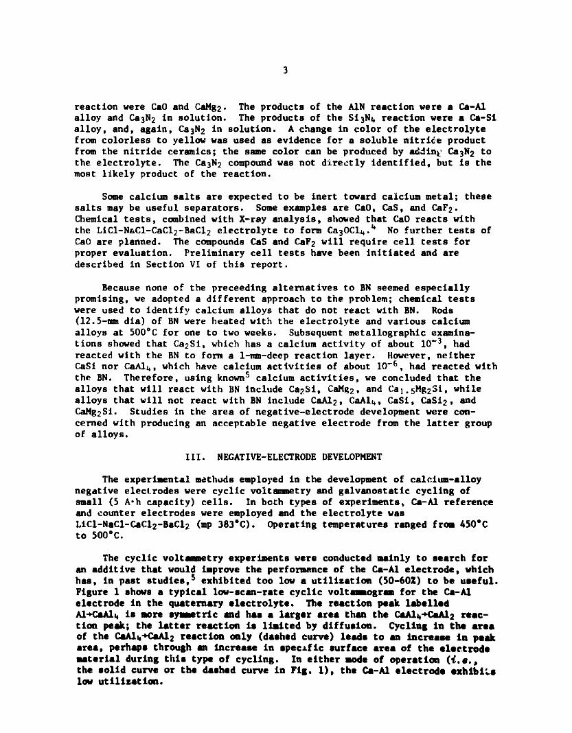
Table 1. Cell Test Summary
Operation UtilizationCell No. % Theo.(Theo. A-h) Type h Cycles (at 10-20 mA/cm2)
CA-19 (120) CaSi/FeS 1000 60 36%
CA-20 (120) CaSi/FeS 1560 110 35%
CA--21 (145) CaSi/FeS2 200 9 43%
CA-22 (141) CaSi/FeS2 0 0 -
CA-23 (119) CaSi/FeS2 577 22 58%
CA-24 (154) Ca-Al-Si/FeS2 >3200 >94 60%
CA-25 (112) Ca2Si/FeS2 0 0
CA-26 (60) Ca-Al-Si/FeS 2100 94 71%
Cells CA-19 and CA-20 were 1.35-V CaSi/FeS cells started in a one-third-charged state by using mixtures of electrode materials (i.e., CaSi2 and CaSiin the negative electrodes and Fe, CaS, and FeS in the positive electrodes).The desired cell discharge reaction, following a full charge, was
2 CaSi + FeS -+ CaSi2 + Fe + CaS (1)
However, the cells were incapable of accepting a full charge; they insteadoperated at about one-third of their theoretical capacity (see Table 1).Through the use of a nickel-sulfide reference electrode in these cells, thecharging problem was ultimately traced to a poor starting material, CaSi2 ,which proved to be very difficult to activate.
Although the electrode utilizations in CA-19 and CA-20 were poor, thecells (and their reference electrodes) provided an excellent electrochemicaltest of the connections between Ca2Si formation, BN-separator degradation,and the increase in cell resistance. This electrochemical test was conductedby charging the two cells in different ways. Cell CA-19 was operatedthroughout its cycle life on the available CaSi and FeS capacity, which wasabout one-third of the theoretical capacity. The reference electrode con-firmed that Ca2Si was not being formed in the negative electrodes of cellCA-19. (When Ca2Si is formed, the cell emf increases by about 0.3 V.) Noresistance increase occurred during the 1000-h test of cell CA-19; theresistance remained constant at 7 m. Thus, it was established that resis-tance increases in calcium cells could be avoided through conservative opera-tion of the cell. Cell CA-20 operated the same way as cell CA-19 (i.e., no
resistance increase) for about 500 h. At that point in the operation, thecell was intentionally charged into the Ca2Si reaction by raising the chargecutoff voltage to 1.9 V. The reference electrode indicated that Ca2Si wasindeed being formed in the negative electrode, and the cell resistanceincreased from 7 ma to about 15 mA within a few cycles. This test establishedthe connection between Ca2Si formation, BN-separator degradation, and the

10
increase in cell resistance. These two cell tests directed the separator-chemistry studies and negative-electrode development studies toward lowercalcium-activity alloys (e.g., Ca-Al-Si).
The cycling tests of cells CA-19 and CA-20 were both terminated becauseof declining coulombic efficiency (from 100% in early cycles to about 50%near termination of the tests). The cause of the declining efficiency wasnot identified in post-test analyses of these cells.
The next three cells, CA-21, -22, and -23, were attempts to use thecompound CaSi as the negative electrode. These cells were started in thefully charged state so that no CaSi2 would be required (the CaSi2 had beenfound to be poor starting material in cells CA-19 and -20). One of the threecells (CA-22) failed on startup because of a mechanical problem; the othertwo cells had poor cycle lives, exhibiting severe declines in coulombicefficiency within 25 cycles. Post-test analyses were not able to identifythe, cause of this failure mode. However, the failures may have been causedby pome impurity (e.g., a silicate) in the CaSi, which assayed only 96% pure.
Cell CA-24 was the first test of the new Ca-Al-Si negative electrode;this test has been highly successful. In Fig. 6, the operating history ofthe cell is summarized. Note that there has been only a slight decline incell capacity (from 93 to 81 A-h) through more than 3200 h of cell opera-tion. This is a great improvement over the rate of decline in earlier cells(25%/1000 h). The cell resistance has also been reasonably stable; itremained at 7 mA2 through 60 cycles. However, the resistance increased to
100
60 --
40
100
: 80
S100
80 Ib 16 16
60 16
40 - 33FIGURES REFER TOW 80 DISCHARGE CURRENT
2 20 DENSITY IN mA/cnt
0 20 40 60 80 100CYCLE NUMBER
Fig. 6. Operating History of Cell CA-24
11
10 mQ after a vacuum treatment at cycle 60. Since then, the resistance hasremained at 10-11 mQ. It is not known at this time if the vacuum treatmentwas somehow responsible for the resistance increase; post-test analyses willbe needed to determine the cause of this problem. The cell operation isbeing continued to test the long-term stability of the BN separator in con-tact with the Ca-Al-Si negative electrode.
It is obvious from Fig. 6 that the specific energy of cell CA-24(47 W-h/kg/5-h rate) is far from the ultimate goal of 160 W-h/kg. However,the cell weight is high (1.79 kg) and the electrodes are quite thick(1.0-1.5 cm). Optimization of the coll components should lead to a specificenergy near the program goal since the theoretical specific energy of theCa-Al-Si/FeS2 couple is about 610 W-h/kg.
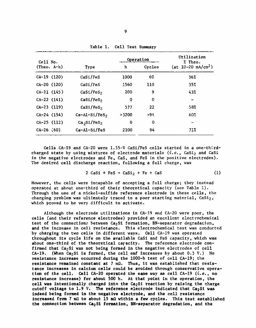
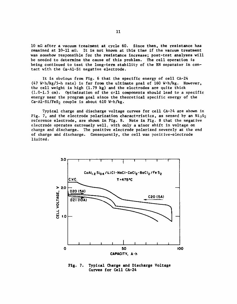
Typical charge and discharge voltage curves for cell CA-24 are shown inFig. 7, and the electrode polarization characteristics, as sensed by an Ni3S2reference electrode, are shown in Fig. 8. Note in Fig. 8 that the negativeelectrode operates extremely well, with only a minor shift in voltage oncharge and discharge. The positive electrode polarized severely at the endof charge and discharge. Consequently, the cell was positive-electrodelimited.
3.0
> 2.0
0
-J
-J
W 1.0
0 10050CAPACITY, A -h
Fig. 7. Typical Charge and Discharge VoltageCurves for Cell CA-24
CoAl 1.2 Si0 .4 / LiCI -NoCI-CoCI 2 -BoCI 2 /Fe S2
C.V.C. T *475*C
D20 (5A)
C20 (5A)D21 (I A)
F

12
+2.0 - - 0
Ni 3S 2 REFERENCE ELECTRODE IN CELL CA- 24I-5AT- 475C
z .O-IzWw +1.0 ----D-20---
---- - mC-20 W
D-20 -C-20- ---2 W
POSITIVE ELECTRODE LIMITS0 CHARGE AND DISCHARGE w
z
-1.0 -30 50 100
CAPACITY, A -h
Fig. 8. Electrode Polarization Characteritics forCell CA-24. (Dashed curve is negativeelectrode; solid curve is positiveelectrode.)
Cell CA-25 was a first attempt at using CaS powder as a separatormaterial. This separator is expected to be unaffected by high calcium-activity compounds such as Ca2Si. Consequently, the cell was based on theCa2Si/FeS2 couple, which has a theoretical specific energy of 790 W-h/kg.However, the cell shorted while being filled with molten salt. The shortwas traced to a defect in the positive-electrode current collector, whichbroke and contacted the negative electrode. The current-collector design is
being revised.
Cell CA-26, a Ca-Al-Si/FeS bicell, was the second cell tested with thenew negative-electrode material (see Table 1). This cell was the first thin-electrode cell tested in the program; the positive electrode and the twonegative electrodes were each 0.3-cm thick. This cell achieved the highest
utilization obtained to date from a bicell (i.e., 71%). This test suggeststhat an FeS-type cell may ultimately achieve a fairly high level of nerfor-mance (400 W-h/kg). From the high utilization obtained by cell CA-26, itappears that thinner cells will have a higher performance than the thickercells which have been tested in the past. Thin-electrode FeS2 cells are nowbeing constructed to test this hypothesis. Cell CA-26 failed in an unusualmanner; its coulombic efficiency declined steadily with cycling from 100% inearly cycles to 35% after 2100 h (94 cycles). The cell has been submittedfor post-test examination to locate the source of this unusual short circuit.
13
VII. CONCLUSIONS
The work described in this report has led to identification of thevarious components needed to fabricate a high-performance calcium cell ofreasonably long life. These components are (1) the Ca-Al-Si negative elec-trode, (2) the FeO.93Co0.07S2 positive electrode, (3) a BN-felt separator,(4) iron negative and molybdenum positive current collectors, and(5) LiCl-NaCl-CaCl 2 -BaCl 2 electrolyte. In the coming year, these componentswill be employed in a number of cells to evaluate their ultimate performancecapabilities.
Although work on the FeS-type cell has indicated that this system mayultimately yield a reasonable specific energy (4100 W-h/kg), the mostpromising system at present is the FeS2 -type cell; future studies will,therefore, focus on this type of cell.
ACKN MWLEDGMENTS
The authors are grateful for the assistance of J. F. Lomax,J. R. Godshalk, W. Moore, C. C. Marcelo, and L. G. Bartholme in conductingthe experiments.
14
REFERENCES
1. D. L. Barney et al., High Performonce Batteries for Electric-VehiclePropulsion and Stationary Energy Storage, Progress Report for thePeriod October 1978-September 1979, Argonne National Laboratory ReportANL-79-94 (Mar 1980).
2. L. E. Ross, S. K. Preto, N. C. Otto, C. C. Sy, and M. F. Roche, Proc.15th Intersoc. Energy Conversion Ens. Conf., Seattle, WA, August 18-22,1980, American Institute of Aeronautics and Astronautics, New York, NY,pp. 581-585 (1980).
3. R. A. Sharma and T. G. Bradley, Extended Abstract No. 149 ExtendedAbstract Vol. 79-2, The Electrochemical Society, Inc., Princeton, NJ(1979).
4. E. M. Levin, C. R. Robbins, and H. F. McMurdie, Phase Diagrams forCeramists--1975 Supplement, American Ceramic Society, Columbus, OH(1975).
5. S. K. Preto, L. E. Ross, A. E. Martin, and M. F. Roche, Calciwn/IronSulfide Secondary Cells, Proc. Symp. on Electrode Mat. and Processesfor Energy Crvvers. and Storage, Eds. J. D. E. McIntyre, S. Srinivasen,F. G. Will, The Electrochemical Society, Inc., Princeton, NJ, Vol. 77-6(1977).
6. E. I. Gladyshevskii, P. I. Kripyakevich, and 0. I. Bodak, UkrainskiiFizicheskii Zhurnal 12, 447 (1967).
7. P. A. Nelson et al., High Perfoirmance Batteries for Electric-VehiclePropulsion and Stationary Energy Storage, Progress Report for thePeriod October 1977-September 1978, Argonne National Laboratory ReportANL-78-94 (1978).