Embed Size (px)
Citation preview

7/27/2019 Anticollision 300 03 Jun 02
http://slidepdf.com/reader/full/anticollision-300-03-jun-02 1/43
Drilling and Measurements Procedures Standard Anticollision
Standard Anticollision Procedures
Version 3.00
Proprietary NoticeThis information is confidential and is the trade secret property of Schlumberger. Do not use, disclose, or reproduce without prior written permission of Schlumberger. Schlumberger makes no warranties; express,
implied, or statutory, with respect to the product described herein, including without limitation, any warrantiesof merchantability or fitness for a particular purpose.
Unpublished work © 2002 Schlumberger All rights reserved under copyright law
All marks mentioned are trademarks or registered trademarks of their respective owners.
Confidential

7/27/2019 Anticollision 300 03 Jun 02
http://slidepdf.com/reader/full/anticollision-300-03-jun-02 2/43
Drilling and Measurements Procedures Standard Anticollision
Document Information
Document Type Standard Anticollision Procedures
Software Version Microsoft Word 2000 for Windows 2000Source File Anticollision - 3.00.doc
Author Chris ChiaAuthor Information Drilling Planning and Surveying Product Champion
Sugarland Product Center 150 Gillingham Lane MD 150-2,
Sugar Land,Texas 77478, USATel: (281) 285 7350
email [email protected]
Revision History 03-Jun-02 First Version Released to Field V-3.00
Review and approval John McCullagh Manager – Surveying & Telemetry
Confidential

7/27/2019 Anticollision 300 03 Jun 02
http://slidepdf.com/reader/full/anticollision-300-03-jun-02 3/43
Drilling and Measurement Procedures Standard Anticollision
Table of Contents
STANDARD A NTICOLLISION PROCEDURES ..................................................................................................................... 1 1.1 Scope ...........................................................................................................................................................................1
1.2 Application ...........................................................................................................................................................1
1.3 Competency ...........................................................................................................................................................1
1.4 Database Quality and Verification...............................................................................................................................21.5 Anticollision Scan in Well Design File .........................................................................................................................2
1.6 Definitions ...........................................................................................................................................................3
1.6.1 Standard Anticollision Procedures..................................................................................................................................3
1.6.2 Separation Factor.............................................................................................................................................................3
1.6.3 Oriented Separation Factor..............................................................................................................................................4
1.6.4 Center to Center Distance ...............................................................................................................................................4
1.6.5 Anticollision Scan Report - Local Minima.....................................................................................................................5
1.6.6 Allowable Deviation From Plan......................................................................................................................................5
1.6.7 Minimum Allowable Separation .....................................................................................................................................5
1.6.8 3D Least Distance ...........................................................................................................................................................6
1.6.9 Normal Plane...................................................................................................................................................................6
1.6.10 Horizontal Plane..............................................................................................................................................................7
1.6.11 Traveling Cylinder Plot...................................................................................................................................................8 1.7 Well Classification.........................................................................................................................................................9
1.7.1 Single Well ......................................................................................................................................................................9
1.7.2 Nearby Well.....................................................................................................................................................................9 1.8 Survey Program Design ................................................................................................................................................9
1.8.1 General ............................................................................................................................................................................9
1.8.2 Survey Redundancy.........................................................................................................................................................9
1.8.3 Survey Program Parts....................................................................................................................................................10 1.9 Anticollision Scanning.................................................................................................................................................10
1.9.1 Global Scan ...................................................................................................................................................................10
1.9.2 Proximity Scan ..............................................................................................................................................................11
1.9.3 Treatment for Sidetracks ...............................................................................................................................................11
1.9.4 Error Models and Dimensionality .................................................................................................................................12 1.10 Anticollision Rules.......................................................................................................................................................13
1.10.1 General Rule..................................................................................................................................................................13
1.10.2 Alert Zone......................................................................................................................................................................13
1.10.3 Minor Risk Well............................................................................................................................................................141.10.4 Major Risk Well ............................................................................................................................................................14
1.10.5 Surface Hole Anticollision............................................................................................................................................14
1.10.6 Standard Anticollision Rules Summarized ...................................................................................................................15
1.10.7 Minimum Separation Rule Summarized.......................................................................................................................18 1.11 Anticollision Reporting ...............................................................................................................................................19
1.11.1 Summary Scan Report...................................................................................................................................................19
1.11.2 Detailed Scan Report.....................................................................................................................................................19 1.12 Traveling Cylinder Plot ..............................................................................................................................................20
1.12.1 General ..........................................................................................................................................................................20
1.12.2 Traveling Cylinder Coordinates....................................................................................................................................20
1.12.3 Relative Depth...............................................................................................................................................................21
1.12.4 Highside Referenced Traveling Cylinder Plots ............................................................................................................21
1.12.5 Tolerance Lines .............................................................................................................................................................21
1.12.6 Drawing Tolerance Lines ..............................................................................................................................................22
1.12.7 Use of Traveling Cylinder Plot While Drilling.............................................................................................................221.12.8 Traveling Cylinder Plot - Document Control ...............................................................................................................22
1.13 Anticollision Monitoring.............................................................................................................................................23
1.13.1 Execution.......................................................................................................................................................................23
1.13.2 Wellsite Survey Validation ...........................................................................................................................................23
1.13.3 Close Approach to a Tolerance Line.............................................................................................................................24
1.13.4 Violation of Tolerance Lines ........................................................................................................................................24
1.13.5 Unexpected Collision Detection ...................................................................................................................................25
3rd June 2002 Confidential i

7/27/2019 Anticollision 300 03 Jun 02
http://slidepdf.com/reader/full/anticollision-300-03-jun-02 4/43
Drilling and Measurement Procedures Standard Anticollision
Table of Contents (cont)
1.14 Anticollision Monitoring Program.............................................................................................................................26
1.14.1 General ..........................................................................................................................................................................26
1.14.2 Application ....................................................................................................................................................................26
1.14.3 Roles and Responsibilities ............................................................................................................................................27
1.14.4 Surveying Procedure .....................................................................................................................................................281.14.5 Shut-in Criteria ..............................................................................................................................................................28
1.14.6 Poorly Surveyed Offset Wells.......................................................................................................................................29
1.15 Magnetic Interference.................................................................................................................................................28
1.15.1 General ................................................................................................................................................................................29
1.15.2 Changeover Between Gyro and MWD Surveys .................................................................................................................30
1.16 Appendix A – Standard Anticollision Procedures: Guidelines................................................................................30
1.16.1 Guideline 1 - Anticollision Scanning by Survey Program Parts ........................................................................................31
1.16.1.1 Survey Program........................................................................................................................................31
1.16.1.2 Survey Program Parts...............................................................................................................................33
1.16.1.3 Anticollision Scanning by Parts...............................................................................................................33
1.16.1.4 Interpretation of Anticollision Scan Reports...........................................................................................34
1.16.1.5 Iteration ....................................................................................................................................................34
1.16.2 Guideline 2 - Drawing Tolerance Lines on a Traveling Cylinder Plot...............................................................................35
1.16.2.1 General .....................................................................................................................................................35
1.16.2.2 Basic Method ...........................................................................................................................................351.16.2.3 No-Go Circles ..........................................................................................................................................36
1.16.2.4 Tolerance Lines........................................................................................................................................37
1.16.2.5 Transferring Tolerance Lines...................................................................................................................38
1.16.2.6 Color Coding Tolerance Lines.................................................................................................................38
1.16.2.7 Traveling Cylinder Plots Versus Spider Plots .........................................................................................39
References .........................................................................................................................................................39
3rd June 2002 Confidential ii

7/27/2019 Anticollision 300 03 Jun 02
http://slidepdf.com/reader/full/anticollision-300-03-jun-02 5/43
Drilling and Measurement Procedures Standard Anticollision
This page intentionally left blank.
3rd June 2002 Confidential iii
7/27/2019 Anticollision 300 03 Jun 02
http://slidepdf.com/reader/full/anticollision-300-03-jun-02 6/43
Drilling and Measurement Procedures Standard Anticollision
Standard Anticollision Procedures
1.1 Scope
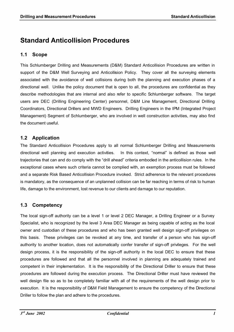
This Schlumberger Drilling and Measurements (D&M) Standard Anticollision Procedures are written in
support of the D&M Well Surveying and Anticollision Policy. They cover all the surveying elements
associated with the avoidance of well collisions during both the planning and execution phases of a
directional well. Unlike the policy document that is open to all, the procedures are confidential as they
describe methodologies that are internal and also refer to specific Schlumberger software. The target
users are DEC (Drilling Engineering Center) personnel, D&M Line Management, Directional Drilling
Coordinators, Directional Drillers and MWD Engineers. Drilling Engineers in the IPM (Integrated Project
Management) Segment of Schlumberger, who are involved in well construction activities, may also find
the document useful.
1.2 Application
The Standard Anticollision Procedures apply to all normal Schlumberger Drilling and Measurements
directional well planning and execution activities. In this context, “normal” is defined as those well
trajectories that can and do comply with the “drill ahead” criteria embodied in the anticollision rules. In the
exceptional cases where such criteria cannot be complied with, an exemption process must be followed
and a separate Risk Based Anticollision Procedure invoked. Strict adherence to the relevant procedures
is mandatory, as the consequence of an unplanned collision can be far reaching in terms of risk to human
life, damage to the environment, lost revenue to our clients and damage to our reputation.
1.3 Competency
The local sign-off authority can be a level 1 or level 2 DEC Manager, a Drilling Engineer or a Survey
Specialist, who is recognized by the level 3 Area DEC Manager as being capable of acting as the local
owner and custodian of these procedures and who has been granted well design sign-off privileges on
this basis. These privileges can be revoked at any time, and transfer of a person who has sign-off
authority to another location, does not automatically confer transfer of sign-off privileges. For the well
design process, it is the responsibility of the sign-off authority in the local DEC to ensure that these
procedures are followed and that all the personnel involved in planning are adequately trained and
competent in their implementation. It is the responsibility of the Directional Driller to ensure that these
procedures are followed during the execution process. The Directional Driller must have reviewed the
well design file so as to be completely familiar with all of the requirements of the well design prior to
execution. It is the responsibility of D&M Field Management to ensure the competency of the Directional
Driller to follow the plan and adhere to the procedures.
3rd June 2002 Confidential 1

7/27/2019 Anticollision 300 03 Jun 02
http://slidepdf.com/reader/full/anticollision-300-03-jun-02 7/43
Drilling and Measurement Procedures Standard Anticollision
It is also the responsibility of D&M Field Management to ensure that, should a change in well trajectory be
required once drilling has commenced, all anticollision planning is correctly redone and signed off by a
competent authority. This last point is very important and requires that the contingency to re-plan a well
at short notice due to unforeseen circumstances has been discussed in advance, and that the competent
sign-off authority in such a situation, has been identified.
1.4 Database Quality and Verification
In satisfying the standard anticollision procedures, verification of the definitive survey database is a key
element. It’s identification and location must be indicated in the well design file and it is incumbent on the
DEC’s to take all reasonable precautions to ensure that it is complete and accurate. Each borehole,
sidetrack, fish and cased or abandoned well must have a separate concatenated top to bottom definitive
survey that uniquely describes the wellpath position from start to finish. In the ideal case, the DEC would
be performing all Survey Management services for the client and so would have total control and be
directly responsible for database quality. In many circumstances however, this will not be the case and
the upkeep of the database will be the responsibility of the client or a third party contractor. Such a
database may contain legacy data acquired over a period of several years by many different service
providers and its quality may be suspect. When D&M takes over a directional drilling contract from a
competitor, it is vitally important to audit the information received on existing wells and verify that it is
complete and accurate. More details on this are contained in the database and data handling procedure.
If this verification cannot be made for whatever reason, then Schlumberger needs to be indemnified in
writing by the client concerned. For any database other than the definitive one to be used for anticollision
scanning, a clear and auditable process must exist and must have been adhered to ensure that it is
identical to the definitive database, even though it may only contain a subset of the data appropriate for
the drilling area. During drilling, the definitive survey database must contain the most up to date as-drilled
surveys to remain valid, until such time as it is updated with the final definitive survey.
1.5 Anticollision Scan in Well Design File
It is mandatory that the well design file, as specified in the Well Design Procedures, contains a section
that lists adequate anticollision scanning information to demonstrate that the well proximity situation is
known at all stages of drilling, and that the clearances between all nearby wells are sufficient to avoid any
potential unplanned collision. The Global Scan (see section 1.9.1) must always be completed, and a
summary scan report (from the proximity scan) must be included in the well design file which lists all wells
identified by the Global Scan.
3rd June 2002 Confidential 2

7/27/2019 Anticollision 300 03 Jun 02
http://slidepdf.com/reader/full/anticollision-300-03-jun-02 8/43
Drilling and Measurement Procedures Standard Anticollision
1.6 Definitions
Particular regard must be paid to the definitions below, as many of the terms listed, although commonly
used throughout the industry, do not always mean the same thing.
1.6.1 Standard Anticollision Procedures
Standard Anticollision Procedures specifically refer to Schlumberger Drilling and Measurement’s
treatment of the well proximity problem using separation factors, oriented separation factors, allowable
deviation from plan and clearance distances as defined below. These procedures are compliant with
Schlumberger Drilling Office software. The use of Oriented Separation Factors requires the use of
approved Drilling Office software versions from V-3.0 onwards.
1.6.2 Separation Factor
The traditional definition of separation factor used by Schlumberger, is defined as the ratio of the center-
to-center distance between wells and the sum of the radii (major semi-axis) of the ellipsoids of
uncertainty, between the subject and offset wells being scanned, with allowance being made for the hole
diameters.
Subject Well
Offset Well
Center-to-Center
Distance
Ellipsoids of
Uncertainty
Allowance for Subject Well
and Offset Well Hole Radii
Major Semi-Axis + Hole
Radii Projected in a Sphere
fig 1: Separation Factor = 1 (Projected Spheres are Touching)
Well collision risk has traditionally been managed by considering the clearance between spheres that
contain the Ellipsoids of Uncertainty (EOU) as shown above. However, using this simplistic approach, it
is possible to have two collision scenario’s with the same Separation Factor, but which have very different
probabilities of collision because the orientation and shape of the EOU’s are not accounted for. This can
result in overly conservative well planning, which can be unnecessarily restrictive. Oriented Separation
Factor (OSF) is a new method of Safety Factor definition that takes into account the geometry of the
EOU’s so that all scenarios with the same Safety Factor have the same probability of collision.
3rd June 2002 Confidential 3
7/27/2019 Anticollision 300 03 Jun 02
http://slidepdf.com/reader/full/anticollision-300-03-jun-02 9/43
Drilling and Measurement Procedures Standard Anticollision
The adoption of this new Oriented Separation Factor (OSF) by Schlumberger Drilling and Measurements
for all future standard anticollision procedures is one of the major advances introduced in these
procedures. Older versions of the anticollision scanning software, which can produce Separation Factor
based results may of course continue to be used to satisfy these procedures, however results in some
circumstances will be more conservative.
1.6.3 Oriented Separation Factor
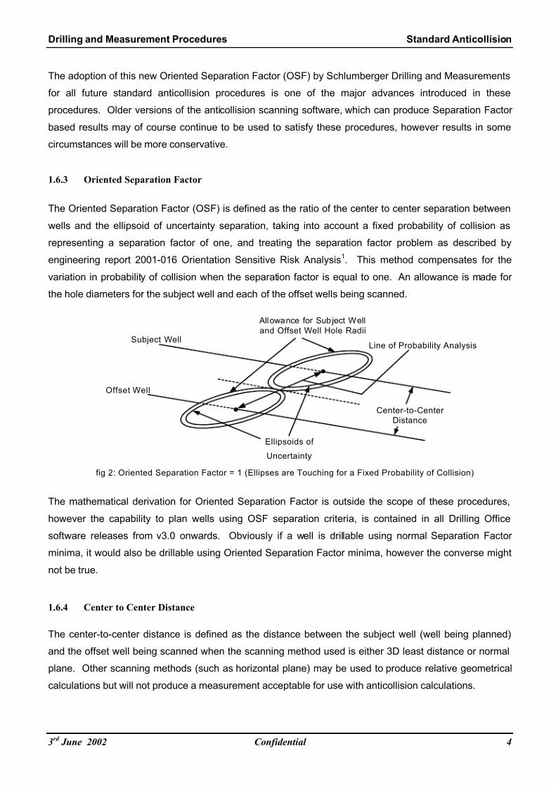
The Oriented Separation Factor (OSF) is defined as the ratio of the center to center separation between
wells and the ellipsoid of uncertainty separation, taking into account a fixed probability of collision as
representing a separation factor of one, and treating the separation factor problem as described by
engineering report 2001-016 Orientation Sensitive Risk Analysis1. This method compensates for the
variation in probability of collision when the separation factor is equal to one. An allowance is made for
the hole diameters for the subject well and each of the offset wells being scanned.
Subject Well
Offset Well
Center-to-Center
Distance
Ellipsoids of
Uncertainty
Allowance for Subject Well
and Offset Well Hole Radii
fig 2: Oriented Separation Factor = 1 (Ellipses are Touching for a Fixed Probability of Collision)
Line of Probability Analysis
The mathematical derivation for Oriented Separation Factor is outside the scope of these procedures,
however the capability to plan wells using OSF separation criteria, is contained in all Drilling Office
software releases from v3.0 onwards. Obviously if a well is drillable using normal Separation Factor
minima, it would also be drillable using Oriented Separation Factor minima, however the converse might
not be true.
1.6.4 Center to Center Distance
The center-to-center distance is defined as the distance between the subject well (well being planned)
and the offset well being scanned when the scanning method used is either 3D least distance or normal
plane. Other scanning methods (such as horizontal plane) may be used to produce relative geometrical
calculations but will not produce a measurement acceptable for use with anticollision calculations.
3rd June 2002 Confidential 4
7/27/2019 Anticollision 300 03 Jun 02
http://slidepdf.com/reader/full/anticollision-300-03-jun-02 10/43
Drilling and Measurement Procedures Standard Anticollision
1.6.5 Anticollision Summary Report – Local Minima
The local minima indicated in the anticollision summary scan report from Drilling Office are defined as the
points of inflection of the approach of the offset well. These are all of the closest points of approach for
each of center-to-center distance, ellipse of uncertainty separation and separation factor, and are
determined regardless of any scanning frequency chosen by the user. A box appearing around the result
indicates the specific parameter that has triggered the reporting of the local minima.
1.6.6 Allowable Deviation From Plan
The allowable deviation from plan (ADP) is defined as the “drilling tunnel” which is created as a result of
the avoidance of any close approach violation identified by the use of oriented separation factors. It is
therefore represented as the radial distance from the plan at any point, to which the driller may be
allowed to depart from the plan during the drilling process for the purposes of drilling efficiency, without
any violation of the “drill ahead” anticollision rules.
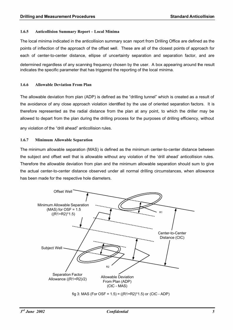
1.6.7 Minimum Allowable Separation
The minimum allowable separation (MAS) is defined as the minimum center-to-center distance between
the subject and offset well that is allowable without any violation of the ‘drill ahead’ anticollision rules.
Therefore the allowable deviation from plan and the minimum allowable separation should sum to give
the actual center-to-center distance observed under all normal drilling circumstances, when allowance
has been made for the respective hole diameters.
Subject Well
Offset Well
Center-to-Center
Distance (CtC)
fig 3: MAS (For OSF = 1.5) = ((R1+R2)*1.5) or (CtC - ADP)
Minimum Allowable Separation
(MAS) for OSF = 1.5
((R1+R2)*1.5)
Allowable Deviation
From Plan (ADP)
(CtC - MAS)
Separation Factor
Allowance ((R1+R2)/2)
R1
R2
3rd June 2002 Confidential 5

7/27/2019 Anticollision 300 03 Jun 02
http://slidepdf.com/reader/full/anticollision-300-03-jun-02 11/43
Drilling and Measurement Procedures Standard Anticollision
1.6.8 3D Least Distance
The 3D least distance method of proximity scanning calculates the nearest distance to each offset well by
stepping down the subject well at specified intervals. At each step this analysis scans the offset well to
determine a plane that is normal to the offset well survey, and which intersects the subject well at the
interval point. Mathematically, this distance is the shortest (least) distance between the subject well and
the offset well from each of the respective subject well scanning points.
Subject WellOffset Well
Scanning Points
fig 4: 3D Least Distance Scanning Method
3D Least Distance
1.6.9 Normal Plane
The normal plane method of proximity calculation steps down each offset well at the specified intervals.
This stepping down of each offset well is done to ensure that the proximity of the entire offset well is
analyzed, and to ensure the scanning of any potential perpendicularly approaching wellbore. At each
step down the offset well this method scans the subject well to determine where a plane normal to the
subject well intersects the offset well at the respective scanning point.
Subject WellOffset Well
Scanning Points
fig 5: Normal Plane Scanning Method
Normal Plane Distance
(3D Least Distanc
3rd June 2002 Confidential 6

7/27/2019 Anticollision 300 03 Jun 02
http://slidepdf.com/reader/full/anticollision-300-03-jun-02 12/43
Drilling and Measurement Procedures Standard Anticollision
It should be noted that both scanning methods, 3D least distance and normal plane, suffer from different
but distinct boundary condition weaknesses, and therefore both methods must be used during the
anticollision scanning process in order to fully investigate the potential for collision. As a result of the
possibility of relative scale distortion, the normal plane method is the preferred method of anticollision
scanning for the purposes of producing the Traveling Cylinder plot (see section 1.6.11).
1.6.10 Horizontal Plane
The horizontal plane method of proximity scanning steps horizontally down the subject well at specified
intervals. This proximity scanning method is not to be used as an anticollision tool and is mentioned here
for the sake of completeness only.
3rd June 2002 Confidential 7

7/27/2019 Anticollision 300 03 Jun 02
http://slidepdf.com/reader/full/anticollision-300-03-jun-02 13/43
Drilling and Measurement Procedures Standard Anticollision
1.6.11 Traveling Cylinder Plot
A traveling cylinder plot is a polar plot centered on the subject survey. This plot displays the intersections
of the offset surveys with the selected projection plane. The Schlumberger standard for the traveling
cylinder plot will be Normal Plane scanning method and North Referenced orientation. No-go circles or
tolerance lines may be used on the traveling cylinder plot to ensure compliance with these procedures.
Their preparation and use will be discussed in more detail later in this document (see section 1.16.1).
Plot is Projected in Normal Plane to
Preserve Relative Scale
Offset Well
fig 6: Travelling Cylinder Plot
Offset Well Subject Well
Travelling Cylinder Plot View
NORTH
10
20
30
40
Subject Well
Travelling Cylinder Plot View Plot Rings are projected normal
to subject well at all times
3rd June 2002 Confidential 8

7/27/2019 Anticollision 300 03 Jun 02
http://slidepdf.com/reader/full/anticollision-300-03-jun-02 14/43
Drilling and Measurement Procedures Standard Anticollision
1.7 Well Classification
1.7.1 Single Well
A well is considered to be a single well when its surface location is at least 24,000 meters (80,000 feet)
distant from the surface location of any other well. This distance is based on the fact that the global scancurrently conducted by all commercial anticollision software is limited to scanning the proximity of the
offset wellheads (ie. surface locations of offset wells) only. In the worst scenario possible with today’s
ERD technology the upper limit on surface well separation at which a well collision could still potentially
take place, is 24,000m, which represents two 12,000m horizontal wells drilled directly towards each other.
Until such time as improvements in software and computer hardware technology make it possible to do
global scans using down hole survey data and not just surface locations, this global scan threshold must
be observed for every anticollision scan. Evidence of the absence of any other nearby wells must be
included in the well design file, and before conferring the status of “single well” in any well planning
exercise.
1.7.2 Nearby Well
Any well that is not a single well is a nearby well.
1.8 Survey Program Design
1.8.1 General
The fundamental purpose of the survey program is to ensure that sufficient quality surveying is carried
out in order to achieve the target at the minimum cost while avoiding unplanned collisions. In doing so, it
is also highly desirable to provide sufficient redundancy of data to ensure that each dataset included in
the final well trajectory has been independently verified. Many operators make this a mandatory
requirement, as it is one of the best methods for the early detection of gross errors due to input of wrong
declination or grid correction etc. This procedure will deal with the aspects of survey program design
specifically related to anticollision (see Appendix A), with target requirements and survey quality having
been defined and satisfied in other procedures.
1.8.2 Survey Redundancy
As mentioned above, for all well designs being executed, it is strongly recommended that no one
individual survey instrument shall be used to define the definitive well trajectory in any single hole section
without its performance having been independently confirmed by another survey instrument. In the case
of a magnetic survey tool this may be done by comparison with overlapping data from any other survey
tool of equal or greater accuracy or alternatively, by the application of an approved multi-station analysis
3rd June 2002 Confidential 9

7/27/2019 Anticollision 300 03 Jun 02
http://slidepdf.com/reader/full/anticollision-300-03-jun-02 15/43
Drilling and Measurement Procedures Standard Anticollision
technique. In the case of a gyroscopic survey tool this may be done by comparison with either
confirmatory magnetic survey data, or sufficient overlapping data from another gyroscopic survey tool.
Every effort must be made to persuade those clients who remain unconvinced, that all our experience,
especially in a crowded subsurface environment, strongly points us in the direction of having survey
redundancy in our survey program design.
1.8.3 Survey Program Parts
A survey program will consist of one or more parts, identified by the various planned drilling stages of the
well (see Appendix A). Each of these parts must be the subject of a separate anticollision scan. The
anticollision scan results for each individual survey program part must be satisfied independently of each
of the other parts. Details of the survey program to be used, and any contingency planned surveys are to
be included in the well design file. In addition, details of each of the survey program parts used for the
scan are also to be clearly indicated. For single wells it may be possible that the survey program consists
of a single survey program part consisting of one or more planned survey instruments. For multi-well
installations, or when dealing with the proximity of other nearby wells, a survey program consisting of
multiple program parts may be required. Generally, a new survey program part can be identified when
the position accuracy of any previously surveyed section of the well improves as a result of having now
been resurveyed by a more accurate survey tool occurring at a later stage in the survey program.
1.9 Anticollision Scanning
1.9.1 Global Scan
The global scan is the initial scan made in the anticollision planning process in order to scan through the
entire database project for all nearby wells that fall within the user specified scan radius. It is strictly
made on the surface location of the wells under consideration. Subsurface survey data is not considered
during this first step. As indicated previously, the scan radius must be set to 24,000 meters (80,000 feet)
in order to identify all nearby wells, or to establish the single well status of the subject well. This global
scan is required to identify the wells that are required to be included into the next step of the anticollision
planning process, the proximity scan. Careful data management, as specified by the survey
management procedures, is required in order to ensure the effectiveness and completeness of the global
scan. The nature of the global scan makes it imperative that fields are stored in a logical order in the
database projects. Nearby wells that have been stored in different database projects cannot be scanned
against each other (see Survey Management Procedures).
3rd June 2002 Confidential 10
7/27/2019 Anticollision 300 03 Jun 02
http://slidepdf.com/reader/full/anticollision-300-03-jun-02 16/43
Drilling and Measurement Procedures Standard Anticollision
1.9.2 Proximity Scan
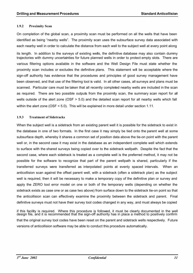
On completion of the global scan, a proximity scan must be performed on all the wells that have been
identified as being “nearby wells”. The proximity scan uses the subsurface survey data associated with
each nearby well in order to calculate the distance from each well to the subject well at every point along
its length. In addition to the surveys of existing wells, the definitive database may also contain dummy
trajectories with dummy uncertainties for future planned wells in order to protect empty slots. There are
various filtering options available in the software and the Well Design File must state whether the
proximity scan includes or excludes the definitive plans. This statement will be acceptable where the
sign-off authority has evidence that the procedures and principles of good survey management have
been observed, and that use of the filtering tool is valid. In all other cases, all surveys and plans must be
scanned. Particular care must be taken that all recently completed nearby wells are included in the scan
as required. There are two possible outputs from the proximity scan, the summary scan report for all
wells outside of the alert zone (OSF > 5.0) and the detailed scan report for all nearby wells which fall
within the alert zone (OSF < 5.0). This will be explained in more detail under section 1.11.
1.9.3 Treatment of Sidetracks
When the subject well is a sidetrack from an existing parent well it is possible for the sidetrack to exist in
the database in one of two formats. In the first case it may simply be tied onto the parent well at some
subsurface depth, whereby it shares a common set of position data above the tie-on point with the parent
well or, in the second case it may exist in the database as an independent complete well which extends
to surface with the shared surveys being copied over to the sidetrack wellpath. Despite the fact that the
second case, where each sidetrack is treated as a complete well is the preferred method, it may not be
possible for the software to recognize that part of the parent wellpath is shared, particularly if the
transferred surveys were transferred as interpolated points at evenly spaced intervals. When an
anticollision scan against the offset parent well, with a sidetrack (often a sidetrack plan) as the subject
well is required, then it will be necessary to make a temporary copy of the definitive plan or survey and
apply the ZERO tool error model on one or both of the temporary wells (depending on whether the
sidetrack exists as case one or as case two above) from surface down to the sidetrack tie-on point so that
the anticollision scan can effectively examine the proximity between the sidetrack and parent. Final
definitive surveys must not have their survey tool codes changed in any way, and must always be copied
if this facility is required. Where this procedure is followed, it must be clearly documented in the welldesign file, and it is recommended that the sign-off authority has in place a method to positively confirm
that the original survey tool codes have been reset on the parent and sidetrack wells respectively. Future
versions of anticollision software may be able to conduct this procedure automatically.
3rd June 2002 Confidential 11

7/27/2019 Anticollision 300 03 Jun 02
http://slidepdf.com/reader/full/anticollision-300-03-jun-02 17/43
Drilling and Measurement Procedures Standard Anticollision
1.9.4 Error Models and Dimensionality (1D, 2D or 3D)
The default standard tool error model type for use in all Schlumberger Drilling and Measurements
anticollision calculations will be the Schlumberger version of the Industry Steering Committee for
Wellbore Survey Accuracy2
model (SLB-ISCWSA). However, the older Topographic model may also
continue to be used. Survey tool error models within the industry are in a continuous state of evolution to
take into account advances in well surveying technology, improved sensor accuracy and attempts at
standardization. Because some clients have a specific preference based on their own experience, there
is provision within the Schlumberger planning software to make use of error model types other than those
listed above however these are not approved for use in anticollision calculations without going through
the exemption process. Where a client or operation requires the use of a non-Schlumberger software
package or error model type for use in any anticollision calculations, then that client is expected to
provide the alternative software application and appropriate training if required. In any case, anticollision
calculations must be duplicated using approved Schlumberger software except where a client or case
specific Area level exemption has been granted by the Area DEC Manager. It is imperative that the
minimum requirements of this procedure are satisfied regardless of which system used for the actual
calculations. The default dimensionality for all anticollision calculations will always be three-dimensional,
and at an uncertainty level of 95% (2.79 sigma). A sign-off authority may grant exemption from the
uncertainty requirement subject to the fulfillment of the appropriate exemption procedure.
3rd June 2002 Confidential 12
7/27/2019 Anticollision 300 03 Jun 02
http://slidepdf.com/reader/full/anticollision-300-03-jun-02 18/43
Drilling and Measurement Procedures Standard Anticollision
1.10 Anticollision Rules
1.10.1 General
The function of the alert zone is to allow the user to clearly identify from the summary scan, which wells
are required to be the subject of a further detailed scan report. In order to do this the separation factor alert type is used in the Drilling Office Close Approach program at the 95% (2.79 sigma) confidence level
and the alert zone threshold set at an oriented separation factor (OSF) of 5.0. At the same time, the
minor risk oriented separation factor threshold should be set to 1.5, and the major risk oriented separation
factor threshold to 1.0. These are the program defaults in any case. Any well identified that violates the
major risk separation factor (OSF < 1.0) will not be considered for exemption without an exhaustive risk
assessment being conducted and only then in very exceptional circumstances. In this case the
exemption to proceed at the increased risk must be signed off by an appropriate Schlumberger Area DEC
Manager and the Area Business Manager. In accordance with policy, it is a fundamental requirement that
all nearby wells exceed the minor risk separation factor of 1.5 and in addition, also satisfy the surfacehole anticollision requirements listed in paragraph 1.10.5. If they do not, the wellbore trajectory must be
re-planned to rectify the problem, or an exemption obtained and the Risk Based Anticollision Procedure
invoked as necessary. During planning, the standard anticollision rules will be applied to any planned well
being scanned against any nearby well, and during execution these rules will be applied to the projected
position ahead of the bit by at least one survey interval as stipulated in the survey program (see appendix
A). Any Schlumberger directional well design that does not fully satisfy this procedure at the planning
stage must be revised or if determined at the execution stage, drilling must immediately stop until a
review is conducted.
1.10.2 Alert Zone
The Alert Zone, which is triggered when any offset well falls between OSF = 5.0 and OSF = 1.5, is
designed for use as an alert tool which allows the user to quickly identify which wells are in closest
proximity to the planned (subject) well, and therefore most likely to be the cause of a proximity issue
during the execution of the plan. The purpose of the Alert Zone is therefore only to provide an indication
of the wells to be included in the “detailed scan” report. For all wells falling outside of the Alert Zone,
evidence of having scanned these wells in the form of the “summary scan” report is sufficient for the
purposes of this procedure.
3rd June 2002 Confidential 13

7/27/2019 Anticollision 300 03 Jun 02
http://slidepdf.com/reader/full/anticollision-300-03-jun-02 19/43
Drilling and Measurement Procedures Standard Anticollision
1.10.3 Minor Risk Well
A minor risk well is an offset well which falls within the proximity filter of OSF = 1.5, but does not violate
the major risk OSF threshold of 1.0 (i.e. the OSF falls between 1.5 and 1.0). This OSF threshold of 1.5
represents the “drill ahead” separation threshold as per policy. Wells which fall below the OSF threshold
of 1.5 will be required to be included in a detailed scan report, in addition to being subject to the
anticollision rules below, and may require exemption for violating the minor risk threshold if the well
trajectory cannot be replanned.
1.10.4 Major Risk Well
A major risk well is an offset well which falls within the proximity filter of OSF = 1.0. This threshold
represents the stop drilling condition, and ordinarily Schlumberger will not proceed with drilling until major
risk wells have been dealt with either by replanning to increase clearance beyond the minor risk
threshold, or replanning to attain minor risk status and subjecting the minor risk well to the risk-based
exemption process.
1.10.5 Surface Hole Anticollision
Surface hole collision risk is the most common proximity problem, particularly where the slot separation
provides minimal clearance from other wells drilled from the same template.
It is well known that standard separation factor anticollision rules are technically weak in this scenario
because of the nature of the separation factor ratio calculation, and the potential for rapid change in the
propagation of survey errors at or near surface. Surveying frequency can also have a large effect on the
surface hole anticollision problem, particularly when steerable drilling assemblies are used for kicking off.
It is therefore crucial that the survey frequency requirements for surface hole as specified in the survey
program are adhered to.
The Well Reference Point is defined as the last known point of departure for any well. For land wells this
would be the wellhead location at ground level, and for offshore wells, this is typically the wellhead
location at seabed. For wells sharing the same physical drilling template or pad, the slot separations are
known exactly from engineering drawings, and therefore because the lateral relative survey errors at this
point are zero, the Allowable Deviation from Plan (ADP) is effectively the side wall to side wall distance
between well conductors. For wells which do not share the same template the relative lateral positionuncertainty between wells is driven by the position fixing accuracy of the survey system used to define
the wellhead location. Modern day systems such as Global Positioning Systems (GPS) which are very
accurate, may be able to reduce this surface uncertainty to within a few meters depending on
geographical location, but more traditional systems are likely to be much less accurate. Therefore any
surface hole rule for wells not sharing the same template must also make allowance for variations in
surface position accuracy.
3rd June 2002 Confidential 14

7/27/2019 Anticollision 300 03 Jun 02
http://slidepdf.com/reader/full/anticollision-300-03-jun-02 20/43
Drilling and Measurement Procedures Standard Anticollision
Subject to the survey frequency requirements being satisfied, the additional mandatory surface hole
anticollision criteria is that a minimum separation of no less than 80% of the ADP at the WRP for wells
sharing the same physical drilling template or pad be maintained, and a 10m minimum separation in all
other cases.
In situations where multiple wells are to be drilled from the same slot or caisson, then the well is
effectively being commenced from a collision situation, and the surface hole will require a detailed close
proximity anticollision monitoring plan (see section 1.14) to be executed at least until the clearance
reaches 10m and the anticollision rules are satisfied and projected surveys clearly indicate divergence
from other sibling wells. Therefore, for all wells to satisfy the standard anticollision procedure for the drill-
ahead condition, the following summary of these requirements must be met:
OSF ≥ 1.5 in addition to Minimum Separation not less than: (80% of ADP at WRP OR 10m)
1.10.6 Standard Anticollision Rules Summarized:
• OSF > 5 in addition to Minimum Separation > 80% ADP (or 10m)
Outside of Alert Zone, Summary Scan Report only required, Drill Ahead.
Subject Well
Offset Well
Center-to-Center
Distance
fig 7: OSF >5 in addition to Minimum Sepa ration > 80% ADP (or 10m)
Oriented EOU Separation > 4*(O-EOU1+ O-EOU
2)
O-EOU1
O-EOU2
3rd June 2002 Confidential 15

7/27/2019 Anticollision 300 03 Jun 02
http://slidepdf.com/reader/full/anticollision-300-03-jun-02 21/43
Drilling and Measurement Procedures Standard Anticollision
• OSF >1.5 in addition to Minimum Separation > 80% ADP (or 10m)
Inside Alert Zone, Detailed Scan Report required, Drill Ahead
Subject Well
Offset Well
Center-to-Center
Distance
fig 8: ·OSF >1.5 in addition to Minimum Separation > 80% ADP (or 10m)
O- EOU Separation > 0.5*(O-EOU1+ O-EOU
2)
O-EOU1
O-EOU2
• 1.5 > OSF >1 in addition to Minimum Separation > 80% ADP (or 10m)
Minor Risk Well, shut in interfering well and resurvey subject well with a more accurate
survey tool to increase OSF above 1.5, or invoke Risk Based Anticollision process and
plan to drill ahead with Line Manager approval and Client written exemption.
Subject Well
Offset Well
fig 9: 1.5 > OSF >1 + Minimum Separation > 80% ADP (or 10m)
O- EOU Separation < 0.5*(O-EOU1+ O-EOU
2)
O-EOU1
O-EOU2
3rd June 2002 Confidential 16

7/27/2019 Anticollision 300 03 Jun 02
http://slidepdf.com/reader/full/anticollision-300-03-jun-02 22/43
Drilling and Measurement Procedures Standard Anticollision
• 1 > OSF or Minimum Separation < 80% ADP (or 10m)
Major Risk Well – STOP DRILLING, Replan trajectory and/or survey program (during
planning phase) to increase OSF above 1.5, Plug back and redrill (during execution
phase) to increase OSF above 1.5, or very exceptionally, invoke Risk Based Anticollision
process and plan to drill ahead with Area approval and Client written exemption.
Subject Well
Offset Well
fig 10: 1 > OSF or Minimum Separation < 80% ADP (or 10m)
EOU's Have Overlapped
Stop Drilling Condition for
Projection Ahead of Bit
3rd June 2002 Confidential 17

7/27/2019 Anticollision 300 03 Jun 02
http://slidepdf.com/reader/full/anticollision-300-03-jun-02 23/43
Drilling and Measurement Procedures Standard Anticollision
1.10.7 Minimum Separation Rule Summarized
Subject WellOffset Well
W ell Reference Point (WRP)
SeaBed
Center-to-Center (CtC)
ADPR
1R
2
f ig 11: W ells Sharing the Same Tem plate or Pad : Minimum Separation = 80% of ADP at WR P
Minimum Separation = 80%*(CtC - (R2 + R2))
At the W RP the re la tive la tera l
survey errors are zero, and so
the ADP is equal to the side-
wall to side-wall distance
Subject Wel lOffset Wel lW el l Reference Point (WR P)
SeaBed
Center-to-Center
R1
R2
f ig12: W el ls Not Shar ing the Same Tem plate or Pad : Minimum Separat ion = 10m
Minimum Se parat ion = 1 0m
Multi-well Slot or Caisson
Well Reference Point (WRP)
SeaBed
Separation Distance
fig13: Wells Sharing the Same Slot
Anticollision Monitoring Plan (see Section 1.14) Req'd Until Separation =10m and OSF>1.5
W1
W2
3rd June 2002 Confidential 18

7/27/2019 Anticollision 300 03 Jun 02
http://slidepdf.com/reader/full/anticollision-300-03-jun-02 24/43
Drilling and Measurement Procedures Standard Anticollision
1.11 Anticollision Reporting
1.11.1 Summary Scan Report
The anticollision summary scan report is obtained by manually running the proximity scan close approach
software for each survey program part. It is required to be listed in the well design file. This summaryreport details each of the center-to-center, ellipse of uncertainty and separation factor minima, as well as
the separation factor alert zone and the anticollision rule violation status of each well scanned. The
purpose of the summary report is to demonstrate that all wells exceed the alert zone separation criteria
(OSF = 5), and therefore the anticollision scan procedure is complete for these wells. In the case where
the proximity of any nearby well triggers any of the alert zones, or crosses the minor or major risk
thresholds, a detailed anticollision scan report as indicated below, must be made on these wells.
1.11.2 Detailed Scan Report
The detailed scan report is obtained by manually running the close approach software for each object
well to be scanned for each survey program part, and is required to be listed in the well design file for
every well that fails to exceed the alert zone separation criteria. The detailed report contains sufficient
information to closely examine the proximity condition of nearby wells that have failed the alert zone filter.
The detailed scan report is also used to examine cases where the major alert or minor alert status has
been violated, in order to offer the well design team a geometrical statement from which to begin any
redesign work that might be required to eventually satisfy these procedures.
A secondary purpose of this report is to indicate where any restrictions in the allowable deviation from
plan (ADP) exist, even when the proximity requirements have been satisfied, in order to review andoptimize for any drilling efficiency issues that may result.
3rd June 2002 Confidential 19
7/27/2019 Anticollision 300 03 Jun 02
http://slidepdf.com/reader/full/anticollision-300-03-jun-02 25/43
Drilling and Measurement Procedures Standard Anticollision
1.12 Traveling Cylinder Plot
1.12.1 General
The traveling cylinder (TC) plot is a polar plot where the center of the plot depicts the relative position of
the subject well plan used to create the plot. Provided the wellpath is drilled exactly on plan, theobserved position will always be at the plot center. This is not realistic however, and so the traveling
cylinder coordinates are usually plotted on the TC plot in real time to monitor the observed position
relative to the plan. In this way, the traveling cylinder is a graphical description of the anticollision scan,
and all of the relevant information on the plot can be obtained from the detailed scan report. At least one
wall-chart sized traveling cylinder plot is a requirement to be sent to the wellsite, and for inclusion in the
well design file, for every well design in which any nearby well, nearby well design or slot bin exists. In
many cases, particularly in high well density areas, it may also be desirable to use more than one
traveling cylinder plot; each one appropriately scaled and detailed for each hole section. The
Schlumberger standard for the traveling cylinder plot will be Normal Plane scanning method and NorthReferenced orientation. In some cases it may also be desirable to produce a wall-chart sized spider plot.
The spider plot is not a substitute for the traveling cylinder plot, and cannot be accepted in its place in the
well design file. The sign-off authority will have the discretionary power to require additional traveling
cylinder plots, and will advise on the most appropriate scale.
1.12.2 Traveling Cylinder Coordinates
Two coordinates can define any point on the polar traveling cylinder plot. The radial distance is the
distance from the center of the plot (when plotting the position of any offset well, this represents the
center to center distance for a given measured depth on the subject well), and the traveling cylinder
azimuth, is the angular coordinate measured relative to the north reference. The angular coordinate
represents the sum of the angle clockwise from the well design highside and the well design azimuth at a
given depth. These coordinates can be obtained from the detailed scan report of the anticollision scan
reporting software and from the anticollision reporting panel in the DDToolbox software. Although both
methods can be used in real time at the wellsite, the use of the close approach software is the primary
planning tool, and the use of the DDToolbox software at the wellsite is the primary execution tool.
3rd June 2002 Confidential 20

7/27/2019 Anticollision 300 03 Jun 02
http://slidepdf.com/reader/full/anticollision-300-03-jun-02 26/43
Drilling and Measurement Procedures Standard Anticollision
1.12.3 Relative Depth
Every object well point plotted on the traveling cylinder must have an associated subject well relative
measured depth for it to provide useful information. This is the surveyed depth along the subject well
design wellpath or in other words, the progress made against the plan. The relative depth for comparison
will generally be the measured depth at that point as a result of using the normal plane scanning method.
This is not the case when other scanning methods (3D least distance or horizontal plane) are used for
this purpose, and the true scale distortions that may arise as a result of using other scanning methods
make them unsuitable for use with the traveling cylinder plot.
1.12.4 Highside Referenced Traveling Cylinder Plots
The use of Highside referenced traveling cylinder plots is not approved for general anticollision. The
reason for this is that the predominant usage requirement for traveling cylinder plots is in the low angle,
high well density area, usually at or near surface. In these circumstances, where the subject well is at or
near low angle, the Highside reference can ‘flip’ around the subject well dramatically as a result of small
changes in orientation. This can have the visual effect of ‘spinning’ the offset wells around the traveling
cylinder artificially, and does not provide any practical usefulness in this scenario. Although it could be
argued that for wells (e.g. sidetracks) which kick-off quickly, or begin a higher angle, the Highside
reference can be a useful traveling cylinder plot, practical experience (of near miss events) suggests that
the risk for misinterpretation of the plot and mistakes is too high to support it’s use. The preferred method
therefore, is to use north referenced traveling cylinder plots, upon which the Highside azimuth may be
indicated if desired.
1.12.5 Tolerance Lines
The main advantages of traveling cylinder plots over any other type of graphical display are their ability to
clearly and accurately display the drilling tolerances or “drilling tunnel”. For any point on a nearby well
that is displayed on the traveling cylinder plot, a line may be drawn around that point which represents the
minimum distance from that point to which the well being drilled can approach without violating the
anticollision rule in force. This line is generally known as a no-go zone, and the distance from the center
of the plot to the edge of the no-go zone represents the allowable deviation from plan. The no-go zone
therefore, is a combination of the separation factor, position uncertainty and hole radii of both the subject
and the offset well in question at that depth. The minimum approach distance defined by the no-go zone
will vary based on the relative orientations of the subject and offset wells, and combinations of no-go
zones for various wells at common depths relative to our planned well may be joined together to
encompass a depth range specific area called a tolerance line.
3rd June 2002 Confidential 21

7/27/2019 Anticollision 300 03 Jun 02
http://slidepdf.com/reader/full/anticollision-300-03-jun-02 27/43
Drilling and Measurement Procedures Standard Anticollision
1.12.6 Drawing Tolerance Lines
Drawing these tolerance lines around every offset well at every point would result in plots that display
several nearby wells quickly becoming unreadable.
It is therefore desirable to draw the tolerance lines such that they summarize the information given by a
number of no-go zones for different nearby wells at a common depth. This can be done with the resulting
tolerance lines color-coded and styled for a specific depth, but must be done in such a way as to prevent
the inadvertent violation of the minimum separation required by the anticollision rules at any depth. An
example of how this might be done is given in the appended guidelines to this procedure, and the sign-off
authority is expected to be able to advise accordingly.
1.12.7 Use of Traveling Cylinder Plot While Drilling
The major premise of the traveling cylinder plot, and all of the anticollision calculations supporting it are
that they are valid for a given survey program, which must be executed accordingly to validate the plan.Major changes (such as the removal of a survey tool run, or a required survey interval being significantly
truncated), will not be made to the survey program without a review of all anticollision calculations, and
regeneration of the traveling cylinder plot. Even minor changes such as start and end depths of survey
intervals for different survey types may have a significant impact on anticollision and should also be
validated accordingly. Any survey frequency requirement stipulated by the survey program must be
observed at all times, and the first response to a failed survey, or failed survey program part must be to
resurvey the section in order to maintain the integrity of the plan and the anticollision calculations.
1.12.8 Traveling Cylinder Plot – Document Control
Each traveling cylinder plot must be verified and signed-off by the appropriate sign-off authority and the
line manager prior to it’s release for client sign-off. A process must be in place to control the version
number, location and method of recall for all copies of all drilling plots as described by the Well Design
Procedures. All traveling cylinder plots required and stipulated in the well design file, must be received at
the rigsite prior to drilling each section. A complete set of the current authorized plots for use at the
wellsite must be held at the DEC, and/or by the D&M Drilling Engineer in the client office, for use and
reference at any time.
3rd June 2002 Confidential 22

7/27/2019 Anticollision 300 03 Jun 02
http://slidepdf.com/reader/full/anticollision-300-03-jun-02 28/43
Drilling and Measurement Procedures Standard Anticollision
1.13 Anticollision Monitoring
1.13.1 Execution
The active and careful monitoring of the position of the well being drilled compared to the well design plan
and its proximity to nearby wells, is critical to the avoidance of any unplanned collision. Drillingperformance and efficiency with regard to allowable deviation from plan must always be secondary to
collision avoidance. The scope for the wellsite team to alter the well design based on operational
circumstances must either be clearly defined and contingency planned, or not conducted without
documentation and the authorization of the sign-off authority. Any instructions sent to the wellsite team
as part of the well design information, or as any subsequent clarification, must be clear on which
instructions are mandatory and which are discretionary or advisory in nature.
1.13.2 Wellsite Survey Validation
Throughout the full quality control life cycle of a survey, the survey tools used must be calibration
checked before and after the survey run. This often takes several days to complete, particularly if the
tools have to return to the base for this to be done. Therefore, there are several levels of survey
validation that are required during this life cycle, one level of which must be at the wellsite at the time of
the survey. Any survey validation conducted at the wellsite must be sufficient to enable a decision to be
made about survey tool change-out or resurvey to be made. When validating surveys during any well
proximity phase of the operation certain mandatory restrictions apply. Tolerance lines are not to be
crossed, and each survey contractor’s own tool specific procedures and quality control procedures for the
tools in use, must be strictly adhered to. The Survey Specialist (or the sign-off authority) may
recommend a suitable contingency for any failed survey program part, and will stipulate the replanning, or
revision of the anticollision calculations and the well design file, if required, as part of that
recommendation.
3rd June 2002 Confidential 23

7/27/2019 Anticollision 300 03 Jun 02
http://slidepdf.com/reader/full/anticollision-300-03-jun-02 29/43
Drilling and Measurement Procedures Standard Anticollision
1.13.3 Close Approach to a Tolerance Line
A close approach to a tolerance line occurs when the oriented separation factor at a position at least one
survey interval projected ahead of the bit reduces sufficiently to threaten the minor risk tolerance line
threshold (OSF = 1.5). In addition, it is good practice that a projection ahead of the bit by at least two
drilling stands is also monitored. Where any projection ahead of the bit will result in a close approach to a
tolerance line the interfering well should be closed in, an attempt must be made to steer away, or the well
must be resurveyed at that point with a more accurate survey tool to increase the oriented separation
factor sufficiently to allow drilling to continue. If neither of these actions is successful and the point is
reached where the projection ahead of the bit crosses the tolerance line, then it is mandatory that drilling
must cease until the situation and plan forward have been fully reviewed by the office based drilling
engineering team. Rig site personnel must not unilaterally cross any tolerance line within the depth
interval to which it applies under any circumstances.
1.13.4 Violation of Tolerance Lines
The team back at the office that has responsibility for the well will review the tolerance line close
approach to determine whether the tolerance line can be relaxed without violating any no-go zones (e.g. if
the line was drawn to smoothly join together two no-go zones), or in case the tolerance line is protecting
another planned well (or wells), and these could be replanned at a later date. Where this proves to be
possible, the team must update the anticollision plots and/or redo the anticollision calculations and
communicate them to the rigsite. In some cases this may be possible by email or fax for minor changes
and where the rigsite has the capability to produce revised plots. If, after review at the office, the
projection ahead of the bit by one survey interval approaches a major risk (OSF = 1), the subject well
must be plugged back, cemented and redrilled before violating the major risk threshold. Alternatively,
drilling must cease pending the well design being replanned having invoked the Risk Based Anticollision
Procedure which will require a risk assessment and written exemption by both the Client and
Schlumberger management. It is important that the Directional Driller remains in control of the situation
at all times and is not afraid to exercise his/her authority to stop the drilling process immediately if the
“drill ahead” criteria are violated.
3rd June 2002 Confidential 24
7/27/2019 Anticollision 300 03 Jun 02
http://slidepdf.com/reader/full/anticollision-300-03-jun-02 30/43
Drilling and Measurement Procedures Standard Anticollision
1.13.5 Unexpected Collision Detection
Experience has shown that despite best efforts at avoidance, an unexpected well collision can occur,
particularly where the legacy survey data is incomplete or inaccurate. Obviously, there is a higher risk of
an unexpected collision when traversing areas of high well density. Extra vigilance is required to look for
indications that this may have occurred including rough, erratic or high torque drilling, especially where
drilling is expected to be smooth or a sudden unexpected change in penetration rate, especially where
the field conditions are well known. Any unexpected cuttings returns, unexpected magnetic interference
of the MWD surveys and vibrations detected at the wellhead of a nearby well may all give prior warning
before the drilling mud is lost or produced hydrocarbons from the nearby well appear at surface. Note
that it has been known for the bit to pass or glance off a nearby well, while a stabilizer or even drillpipe
hard-banding some distance back has penetrated the casing. Extra diligence is required at least until the
top stabilizer has passed the close approach point of a nearby well and not just the bit. The opinion
expressed by some in the industry stating that when the bit is approaching an existing well at a shallow
(glancing) angle, it will always “bounce off” has been proven by hard experience to be a myth and has
resulted is some very expensive remedial work.
1.14 Anticollision Monitoring Program
1.14.1 General
Every well design file must reference the client or project specific anticollision monitoring program for
which the well design has been provided. Where such a program does not exist, or it’s existence is in
doubt, then the well design file shall include a detailed anticollision monitoring program. This program
shall include details of the conditions and circumstances under which the program shall be executed and
anticollision monitoring carried out, with the minimum requirement being described below. It shall also
include roles and responsibilities for each of the key wellsite and onshore personnel involved in
anticollision monitoring, and the manning and resource requirements to ensure successful execution of
the program.
1.14.2 Application
Active anticollision monitoring and close proximity measures should be implemented whenever there is
an increased risk of collision with nearby wells. This would normally be required when nearby wells aresubject to any anticollision shut-in requirements, when there is the possibility or potential for the OSF to
reduce to below 1.5 and trigger the minor risk proximity or whenever any risk based anticollision process
is being executed under an exemption. Each project should set it’s own additional conditions and criteria
to take into account local or governmental regulations, client policies and the known effects of lithology
etc on the behaviour of drilling assemblies in use.
3rd June 2002 Confidential 25

7/27/2019 Anticollision 300 03 Jun 02
http://slidepdf.com/reader/full/anticollision-300-03-jun-02 31/43
Drilling and Measurement Procedures Standard Anticollision
1.14.3 Roles and Responsibilities
• Directional Reference Corrections
Each of the Directional Driller, Survey Engineers and Drilling Engineers is individually responsible for
taking all precautions for checking and double-checking the survey references and reference
correction (i.e. Grid Convergence and Declination) as appropriate, which are in use for any aspect of
this procedure. A useful guide for this check is the signed-off drilling plot provided to the wellsite,
which should clearly display this information on the plot header.
• Directional Driller
Maintain and update the local definitive survey database (which may be a copy of or a subset of the
main definitive survey database as defined by Section 1.4) and conduct anticollision calculations,
including Oriented Separation Factors (OSF), at all times as required using Schlumberger approved
software as new surveys become available and during the execution of the survey program. Confirm
onsite survey quality control requirements, corrections, reference data and their use by surveyengineers, and confirm that independent survey and position calculations performed by surveyors
correlate with the local definitive database.
• Gyro / EMS Survey Engineer
Maintain a complete record of all raw and computed survey data, and independently confirm all
reference corrections and positional calculation data for correlation against the local definitive
database. At the end of each multishot survey, or at least daily, report to the Directional Driller a
hardcopy of all surveys and surveyed position calculations to date.
• MWD Survey Engineer
Maintain a complete record of all raw and computed survey data, and independently confirm all
reference corrections and positional calculation data for correlation against the local definitive
database. At the end of each section and at least daily, report to the Directional Driller a hardcopy of
all surveys and surveyed position calculations to date.
• (Onshore/Office) Drilling / Operations Engineer
Verify all anticollision calculations and surveyed position calculations in use by the Directional Driller
on a daily basis, or more frequently as required, using the definitive survey database, or another
independent and verified copy of the database as appropriate.
3rd June 2002 Confidential 26

7/27/2019 Anticollision 300 03 Jun 02
http://slidepdf.com/reader/full/anticollision-300-03-jun-02 32/43
Drilling and Measurement Procedures Standard Anticollision
1.14.4 Surveying Procedure
During periods of anticollision monitoring where there is a risk of infringing the minor risk rule, or where a
risk based exemption is in force, surveys should be taken every 10m (30ft) or more frequently with either
Surface Readout Gyro (SRG), Northseeking Gyro (NSG), or MWD (providing external magnetic
interference is not an issue). At each survey station the Directional Driller and Operations Engineer
should confirm the survey has been recorded and plotted correctly, and produces the same surveyed
position results on independent systems. In order to protect against gross errors, particularly
unrecognized calibration problems arising, where wireline conveyed gyro survey tools are being used for
singleshots, the survey tools provided at the rigsite should be cycled at least every four runs in hole or
two stands drilled (whichever occurs first). A process should be maintained which confirms surveyed
position across tool changeovers, and the positive seating of the gyro in the UBHO sub. Projections
ahead of the bit should be calculated based on both straight line and trend analysis, based on tool
settings and the last three surveys, with any drilling progress decisions generally taking into account the
worst possible case between the two projections. The OSF should be calculated at the projected position
ahead of the bit, and during periods when the minor risk rule has been infringed, or a risk-based
exemption is in force, the clearance calculations should be independently confirmed at the time of drilling,
by the (Onshore or Office-Based) Drilling or Operations Engineer. Drilling should be delayed until this
confirmation has been completed. Once clear of the minor risk area, or risk based exemption zone, and
diverging from any wells shut-in for anticollision, normal drilling and surveying operations may resume.
Drilling must cease when any inconsistency in any recorded survey is observed, or the anticollision status
or clearance calculation at any stage cannot be confirmed, until the problem is resolved.
1.14.5 Shut-in Criteria
The shut-in criteria must be agreed with the client at the planning stage, and fully documented in the well
design file, particularly where the client has provided written exemption from any of the standard shut-in
criteria below. When the minor risk OSF has been, or is likely to be infringed during drilling operations,
the following shut-in criteria should be observed. Provided that the potential point of collision is above
any shut-in and depressurized subsurface safety valve or plug, drilling may continue, however the
following recommendations should be followed where possible:
• Use a rock bit in preference to a PDC or diamond type.
• Where a drilling motor is used, use low speed in preference to high speed.
• Where there are mud returns, monitor for the presence of cement,
• Where there are mud returns, install a ditch magnet upstream of the shale shakers and
monitor for the presence of metal shavings.
• Control the ROP to reduce the potential for damage should a well collision occur.
3rd June 2002 Confidential 27

7/27/2019 Anticollision 300 03 Jun 02
http://slidepdf.com/reader/full/anticollision-300-03-jun-02 33/43
Drilling and Measurement Procedures Standard Anticollision
• Closely monitor drilling torque.
• Annular pressures on potentially intersecting wells should be monitored continuously for
fluctuations and any such fluctuations reported immediately.
• A listening device may be used on the wellhead of the nearby well that is at risk from
collision.
• When drilling in close approach situations, ensure that the top stabilizer and not just the
bit has safely passed the potentially intersecting well, before drilling ahead at full speed.
When the minor risk OSF has been, or is likely to be infringed during drilling operations and the potential
point of collision is below the depth of any shut-in and depressurized subsurface safety valve or plug,
then the well should either be plugged back and redrilled, or a deeper plug must be set so as to be below
the potential point of collision, and the offset well depressurized. If a deeper plug is set, then drilling may
proceed as above. If, at any time the projected ahead position of the well gives an OSF of equal to or
less than 1.0 then unless the well is immediately resurveyed with a more accurate survey tool to increase
the OSF beyond the minor risk threshold, then the subject well shall be plugged back and redrilled.
1.14.6 Poorly Surveyed Offset Wells
Where the position of any offset well is in doubt as a result of having been poorly surveyed, or it’s position
is not well known for whatever reason, it shall be assigned the worst possible position error model (SLB-
ISCWSA: UNKNOWN) until it’s position can be properly verified. Where this procedure results in a
potential proximity issue involving a well having an UNKNOWN tool code assigned to it then the well
design must either be altered to avoid this problem, or the poorly surveyed well must be the subject of arisk analysis, and the Risk Based Anticollision Procedures should be invoked. No poorly surveyed well
having an UNKNOWN survey tool code shall be allowed to infringe the minor risk OSF without having
been the subject of a risk based written exemption.
1.15 Magnetic Interference
1.15.1 General
The use of magnetic surveys that have been influenced by magnetic interference is one of the major
causes of modern day well collisions. There are two main sources of this interference; external
interference usually coming from nearby casing(s) nearby fish or formations that may exhibit magnetic
properties, and the second source is drillstring originated magnetic interference.
3rd June 2002 Confidential 28
7/27/2019 Anticollision 300 03 Jun 02
http://slidepdf.com/reader/full/anticollision-300-03-jun-02 34/43
Drilling and Measurement Procedures Standard Anticollision
External interference cannot be corrected for, and the only safe alternative is to run gyro surveys during
well proximity situations until clear of it. Drillstring magnetic interference can be corrected for using the
latest Schlumberger multi-station correction algorithm (D-Mag). The underlying assumption for all
anticollision operations involving survey quality control, and the comparison of MWD versus Gyro (or any
other) surveys, is that each survey type has independently met it’s own wellsite quality control
requirement. In other words, the use of Gyros for anticollision proximity surveying will not be halted
unless the comparative MWD survey meets it’s own independent field acceptance criteria and sufficient
confirmatory overlapping surveys have demonstrated correlation. In every case, every offset well, partial
well drilled, fish, sidetrack and abandoned well must be separately contained in the database in it’s own
borehole, and must have a definitive survey in place with survey uncertainty tool codes selected
appropriately to indicate current knowledge of the surveyed status of each well. An exemption is required
if a client elects to drill ahead using only MWD measurements in situations where there is still evidence of
external magnetic interference, even if the gyro and MWD agree at the last gyro survey.
1.15.2 Changeover Between Gyro and MWD Surveys
In situations where magnetic interference is expected on the MWD tool from multiple nearby wells, a
simple calculation can be used during planning as a guideline for predicting where gyro surveys might be
required. This is done by taking the root sum square (RSS) of the center-to-center distances of all of the
offset wells surrounding the subject well at any given depth, and plotting this “overall effective clearance
distance” against measured depth on an x-y plot. This planning technique needs to be calibrated with
real surveys in each area to be useful. During execution, prior to any decision being made to halt taking
gyro surveys, it must be confirmed that the MWD tool is clear of external interference. The only practical
way to ensure that this is the case is by direct comparison of MWD versus Gyro surveys. In determining
what the degree of correlation should be, some allowance must be made for the orientation, geographic
location and BHA configuration (or amount of drillstring interference present), as well as the respective
tool accuracies. This calculation can be done using a software utility, or worksheet, which utilizes the
technique described in the 1997 Anadrill MWD Surveying Procedures3. An upper bound for this
calculation, given the dependent variables are not extreme cases, is unlikely ever to exceed 2° in
azimuth, and 0.5° in inclination. The calculated correlation should be confirmed over at least two
successive surveys where the subject well is positively diverging from any offset well before halting the
use of gyro surveys. A more detailed treatment of magnetic interference summarized here can be found
in the Survey Procedures.
3rd June 2002 Confidential 29

7/27/2019 Anticollision 300 03 Jun 02
http://slidepdf.com/reader/full/anticollision-300-03-jun-02 35/43
Drilling and Measurement Procedures Standard Anticollision
1.16 Appendix A – Standard Anticollision Procedures: Guidelines
The guidelines below are provided as an illustration on the use of the procedures and to provide context.
Unlike the procedures, they are not mandatory. Rather, they serve to help provide a better understanding
of the intent of the procedures. It is the responsibility of each location to ensure that the procedures are
strictly adhered to and that the guidelines are understood.
1.16.1 Guideline 1 - Anticollision Scanning By Survey Program Parts
1.16.1.1 Survey Program
The survey program is the planned series of survey instruments to be used, and surveying requirements
to be met, during the execution of the well design in order to satisfy the Well Surveying and Anticollision
Policy. In general, the survey program forms the link between how we plan to avoid any unintended well
collisions, and how we ensure that we achieve our well positioning objectives and penetration of the
drilling target. Designing a survey program is an iterative process where the objective is to meet all of the
well positioning objectives with the best technical solution in terms of operational efficiency, cost and
accuracy. This is discussed further in the Surveying Procedures, but for the purposes of illustrating the
use of the survey program for anticollision scanning by parts, we can begin with a typical example of a
survey program: In the table below, JORPS are defined as vendor specific Joint Operating and Reporting
Procedures as agreed between the client and the service provider.
Hole Casing Depth From Depth To Survey Tool Vendor Survey Frequency QC Requirements Tool Code Comments
26" - Seabed 865ft Gyro Singleshot Scientific Maximum 30ft SDI JORPS NSG-SSHOT No MWD in 26" BHA - Gyro in UBHO sub as close to Bit as possible
@342ft Cycle between at least 2 tools every 6 runs taking correlation shots
Drillpipe gyro multishot section on last gyro run in hole to confirm singleshots
17 1/2" - 865ft 2975ft MWD SLB Stand (~96ft) SLB JORPS MWD+SAG Gyro singleshots on standby for first 500ft of section in case of external
MW D to be magnetic interference. MW D Surveys to be SAG correctedSAG cor rec ted MWD benchmarks and checkshots requi red as per JORPS on any BHA change
- 13 3/8" Seabed 2950ft Continuous Scientific 25ft SDI JORPS CNSG-CASING Continuous gyro multishot must reach a minimum depth of 2800ft, otherwise
@342ft Gyro Multishot S/Specialist a cleanout trip must be done and the gyro re-run to this depth.
Acceptance Req'd Gyro inrun/outrun and QC report faxed to S/S immediately on completion
12 1/4" - 2975ft 7455ft MWD SLB Stand (~96ft) SLB JORPS MWD+SAG If section completed in a single BHA run, drop EMS multishot on completion.
6 overlapping MW D to be If multiple BHA's used, EMS not required, but ensure a minumum of six
repeats SAG corrected overlapping MW D vs MW D surveys somewhere during trip back in hole.
12 1/4" - 2975ft 7455ft EMS Scientific Stand (~96ft) SDI JORPS EMS+SAG Contingency: Drop EMS multishot if 12 1/4" section is drilled with one BHA.
EMS to be Thi s is for con firmat ion of the MWD onl y, and is requir ed over at leas t 1000f t
SAG corrected of open hole, so need not be dropped at TD depending upon hole condi tion.
- 9 5/8" Seabed 7400ft Continuous Scientific 25ft SDI JORPS CNSG-CASING Continuous gyro multishot must reach a minimum depth of 7200ft, otherwise
@342ft Gyro Multishot S/Specialist or the gyro must be pumped down in drillpipe on trip in hole to this depth.
Acceptance Req'd CNSG-DPIPE Gyro inrun/outrun and QC report faxed to S/S immediately on completion
8 1/2" - 7455ft 11200ft MWD SLB Stand (~96ft) SLB JORPS MWD+SAG If section completed in a single BHA run, drop EMS multishot on completion.
6 overlapping MW D to be If multiple BHA's used, EMS not required, but ensure a minumum of six
repeats SAG corrected overlapping MW D vs MW D surveys somewhere during trip back in hole.
8 1/2" - 7455ft 11200ft EMS Scientific Stand (~96ft) SDI JORPS EMS+SAG Contingency: Drop EMS multishot if 8 1/2" section is drilled with one BHA.
EMS to be Thi s is for con firmat ion of the MWD onl y, and is requir ed over at leas t 1000f t
SAG corrected of open hole, so need not be dropped at TD depending upon hole condi tion.
In order to identify the anticollision scanning steps, we first need to clearly identify the appropriate drilling
stages. This is most easily done graphically, using a ‘Christmas Tree’ diagram. The Christmas Tree
diagram is simply a plot of ellipsoid of uncertainty (EOU) major axis versus measured depth, and is used
to graphically display the effect of each of the various sections of the survey program (using our example
illustrated above).
3rd June 2002 Confidential 30
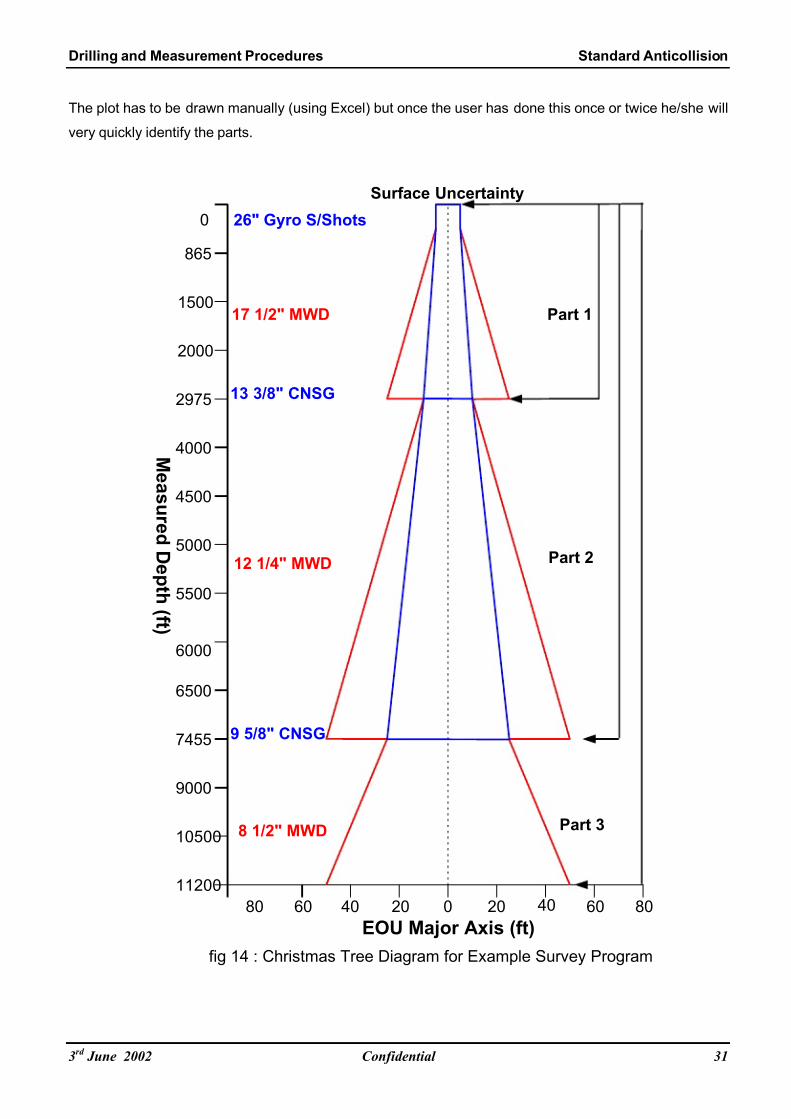
7/27/2019 Anticollision 300 03 Jun 02
http://slidepdf.com/reader/full/anticollision-300-03-jun-02 36/43
Drilling and Measurement Procedures Standard Anticollision
The plot has to be drawn manually (using Excel) but once the user has done this once or twice he/she will
very quickly identify the parts.
M e a s ur e d D e p t h ( f t )
EOU Major Axis (ft)0 20 40 60 8020406080
0
865
1500
2000
2975
4000
4500
5000
5500
6000
6500
7455
9000
10500
11200
Surface Uncertainty
13 3/8" CNSG
9 5/8" CNSG
Part 1
Part 2
Part 3
26" Gyro S/Shots
fig 14 : Christmas Tree Diagram for Example Survey Program
17 1/2" MWD
12 1/4" MWD
8 1/2" MWD
3rd June 2002 Confidential 31

7/27/2019 Anticollision 300 03 Jun 02
http://slidepdf.com/reader/full/anticollision-300-03-jun-02 37/43
Drilling and Measurement Procedures Standard Anticollision
Using our example above, we will simulate a surface uncertainty of 5ft, and then begin by plotting the
resultant increase in EOU (given by the EOU report from the planning software) for each survey program
item in turn. So, we have gyro singleshots in 26” hole down to 865ft, and then MWD to 2975ft. We set
these tool codes in our well design package and generate the 3D 95% EOU report and extract the major
half axis at 865ft and 2975ft. By continuing to complete the plot by changing the survey tool codes in the
well design software to simulate the progress of the execution of the survey program, a Christmas Tree
plot similar to the example above is generated. It can clearly be seen from this that the MWD surveys are
driving the largest EOU generation and we need to complete our anticollision scan using three survey
program parts as given below:
1.16.1.2 Survey Program Parts
Part Hole Casing Depth From Depth To Survey Tool Vendor Survey Frequency QC Requirements Tool Code Comments
26" - Seabed 865f t Gy ro Singles hot Sc ient if ic Max imum 30f t SDI JORPS NSG-SSHOT No MWD in 26" BHA - Gy ro in UBHO s ub as c los e to Bit as pos sible
@342ft Cycle betw een at least 2 tools every 6 runs taking correlation shots
1Drillpipe gyro multishot section on last gyro run in hole to confirm singleshots
17 1/2" - 865f t 2975f t MWD SLB Stand (~96f t) SLB JORPS MWD+SAG Gyro singleshots on standby f or f irst 500f t of section in case of external
MWD to be magnet ic inter ferenc e. MWD Survey s to be SAG c or rec ted
SAG corrected MWD benchmarks and checkshots required as per JORPS on any BHA change
- 13 3/8" Seabed 2950f t Continuous Sc ientif ic 25f t SDI JORPS CNSG- CA SING Continuous gyr o multis hot mus t r eac h a minimum depth of 2800f t, otherw ise
@342ft Gyro Multishot S/Specialist a cleanout trip must be done and the gyro re-run to this depth.
2 Acceptance Req'd Gyro inrun/outrun and QC report faxed to S/S immediately on completion
12 1/4" - 2975f t 7455f t MWD SLB Stand (~96f t) SLB JORPS MWD+SA G If section completed in a single BHA run, dr op EMS multishot on completion.
6 ov er lapping MWD to be If mult iple BHA 's us ed, EMS not required, but ens ure a minumum of six
repeats SAG c or rec ted ov er lapping MWD v s MWD s urvey s s omewh ere dur ing t rip bac k in hole.
12 1/4" - 2975f t 7455f t EMS Scientif ic Stand (~96f t) SDI JORPS EMS+SAG Contingency: Drop EMS multishot if 12 1/4" section is drilled w ith one BHA.
C EMS to be This is for conf irmat ion of the MWD only, and is requ ired over at leas t 1000ft
SAG corrected of open hole, so need not be dropped at TD depending upon hole condition.
- 9 5/8" Seabed 7400f t Continuous Sc ientif ic 25f t SDI JORPS CNSG- CA SING Continuous gyr o multis hot mus t r eac h a minimum depth of 7200f t, otherw ise
@342ft Gyro Multishot S/Specialist or the gyro must be pumped dow n in drillpipe on trip in hole to this depth.
3 Acceptance Req'd CNSG-DPIPE Gyro inrun/outrun and QC report faxed to S/S immediately on completion
8 1/2" - 7455f t 11200f t MWD SLB Stand (~96f t) SLB JORPS MWD+SA G If section completed in a single BHA run, dr op EMS multishot on completion.
6 ov er lapping MWD to be If mult iple BHA 's us ed, EMS not required, but ens ure a minumum of six
repeats SAG c or rec ted ov er lapping MWD v s MWD s urvey s s omewhere dur ing t rip bac k in hole.
8 1/2" - 7455f t 11200f t EMS Scientif ic Stand (~96f t) SDI JORPS EMS+SAG Contingency: Drop EMS multishot if 8 1/2" section is drilled with one BHA.
C EMS to be This is for conf irmat ion of the MWD only, and is requ ired over at leas t 1000ftSAG corrected of open hole, so need not be dropped at TD depending upon hole condition.
1.16.1.3 Anticollision Scanning by Parts
Having identified the survey program parts, we have immediately established that we will require at least
three separate summary scan reports, with the detailed reports being dependent upon the summary scan
results. The first anticollision (a/c) scan will require the surface uncertainty to be set at 5ft, and the Gyro
Singleshot tool code (NSG-SSHOT) to be set from seabed to 865ft. The next step is to set the tool code
to MWD+SAG (in this example), from 865ft downwards. Next, conduct the global scan and then run the
proximity calculation as described earlier in these procedures. Output the summary report and note any
wells that infringe the Alert Zone OSF < 5.0. At this stage it is more efficient to stay in the Close
Approach application and deselect the wells that are clear of the Alert Zone threshold. Then re-run the
proximity scan, and output the detailed report. This completes the anticollision scan for part 1 of the
survey program. The same process is repeated for part two, by returning to the well design package and
setting the survey tool codes to Continuous NSG (CNSG-CASING), down to 2950ft, and then MWD+SAG
onwards.
3rd June 2002 Confidential 32

7/27/2019 Anticollision 300 03 Jun 02
http://slidepdf.com/reader/full/anticollision-300-03-jun-02 38/43
Drilling and Measurement Procedures Standard Anticollision
Run the proximity calculation again, output the summary report, deselect the wells clear of the alert zone
threshold, rerun the proximity calculation and output the detailed scan report. Repeat the process for part
3 of the survey program, by setting the tool codes to CNSG-DPIPE (assuming the gyro had to be pumped
down in this case) from surface, and MWD+SAG to 11,200ft. Repeat the report generation process as
described above.
1.16.1.4 Interpretation of Anticollision Scan Reports
The above process is carried out so that it is now possible to identify any wells that present a danger of
infringing our minor risk or major risk threshold. What happens if on the anticollision scan for part 1 there
is a minor risk well at 5,400ft? Well, typically this is ignored because part 1 only covers from surface to
2,975ft. We would ensure that all of our anticollision rules are satisfied for part 1 over this interval, and
then move on to ensure that each of the other parts do not show proximity problems over their respective
intervals.
1.16.1.5 Iteration
Anticollision planning is an iterative process that requires training and experience to come to an optimized
solution. In many cases the user will have to modify the well design slightly, change the survey program
or perhaps request a change in the geological target size in order to reach a practical compromise.
When any of these changes are made the entire process of identifying the parts, conducting the
anticollision scans and interpreting the results is required to be repeated as described above. Over the
life of a well design, sometimes up to and during actual execution, this process may be repeated many
times and over many iterations using variations in planning, and ultimately combinations of planned and
actual surveyed well position as the well construction progresses.
1.16.1.6 Survey Tool Accuracy Hierarchy
The following table provides a general guideline to the relative survey tool accuracies of the various
generic survey instruments available today.
* MW
Instrument Type Reference ConveyanceRank
RIGS
Continuous Gyro
Northseeking Gyro
MWD / EMS
Remarks
SRG
Photo Singleshot
Inclination Only
NSG Singleshot
Continuous DNI
1
8
7***
6 / 4**
5 / 3*
4
3
2
9
True North
Initialization
Magnetic North
Gravity
Sightline
Incliation
Magnetic
Gyro
Inertial
Gyro
Gyro
Gyro
Magnetic
Magnetic
True North
True North
Magnetic North
Magnetic North
Both
Both
Wireline
Wireline
Drillpipe
Wireline
Drillpipe
Drillpipe
Drillpipe
5.3" OD Min.
1.75" OD Min
Not above 70deg angle
Not above 70deg angle
EMS 1.375" OD Min
Runs not > 40min
Accuracy not defined
Verticality checkshot
Verticality check only
D / EMS are more accurate than gyrocompassing Northseeking Gyro above 70deg inclination.
** SRG is equallt as good as Northseeking gyro in low angle at surface where SRG is less affected by noise.
*** Continuous DNI improves trajectory definition for Geosteering, survey accuracy still being investigated
3rd June 2002 Confidential 33

7/27/2019 Anticollision 300 03 Jun 02
http://slidepdf.com/reader/full/anticollision-300-03-jun-02 39/43
Drilling and Measurement Procedures Standard Anticollision
1.16.2 Guideline 2 - Drawing Tolerance Lines on a Traveling Cylinder Plot
1.16.2.1 General
Having completed an acceptable anticollision scan and produced each of the required reports as
described in the previous guideline, one or more traveling cylinder plots can be prepared. Tolerance lines
can then be drawn on them to aid the driller’s interpretation of his “drilling tunnel” and to define the hard
boundaries that represent the threshold of any minor risk zones. In the example given above, it would be
prudent to prepare three separate traveling cylinder (TC) plots, one for each of the 26” and 17½”
sections. A TC plot for the 12 ¼” and/or 8½” sections will only be required in the event that any offset
wells are within the alert zone radius at these depths. The preparation of the TC plots, their scale ranges
and depth labels requires some experience in order to provide something that is of practical use to the
Directional Driller. If at all possible, the Directional Driller should be involved to personally review the
plots in sufficient time to allow for any changes to be made and for regeneration of the plots if necessary.
1.16.2.2 Basic Method
Having identified the alert zone wells over the interval of each part, a suitable scale range for the tophole
TC plot can be chosen so that all alert zone wells are displayed at least down to a depth of 1,000ft (our
26” hole section finishes at 865ft giving us some early warning of what is ahead for the next section). If
the well being drilled is a sidetrack, or starts at a greater depth than the example given, the initial scale
may have to be larger to accommodate the increased minimum allowable separations (MAS) that will
exist at depth, due to larger position uncertainties having been propagated to that point. Wells can be
removed from the tophole TC plot for clarity only if they do not infringe the alert zone, or are clearly
overshadowed by other wells, which will clearly prevent a proximity issue with the overshadowed more
distant well. This is not recommended however, and a better strategy is to leave all wells in place but
remove unnecessary no-go circles. Having identified the wells required to be placed on the plot, and
chosen to display no-go circles based on the minor risk rule, we can now generate the TC plot (Normal
Plane and North Referenced), by setting our survey tool error model codes to those for part 1 of the
survey program and outputting the TC plot to the graphics display. A typical scale for the tophole TC plot
is likely to be 1in = 5ft (2cm=1m), and for subsequent plots perhaps 1in = 10ft, or 1in = 20ft.
3rd June 2002 Confidential 34

7/27/2019 Anticollision 300 03 Jun 02
http://slidepdf.com/reader/full/anticollision-300-03-jun-02 40/43
Drilling and Measurement Procedures Standard Anticollision
1.16.2.3 No-Go Circles
The no-go circles that are generated are given a frequency based as a function of the scan interval
chosen. Therefore if the scan interval is 100ft, and the no-go circle frequency is set at 1, then no-go
circles will appear at 100ft depth intervals. It is worth noting here that the depth intervals, and any depths
depicted on the TC plot are referenced to the measured depth of the planned (or subject) well only.
Therefore, no-go circles marked as 600ft, refer to a measured depth of 600ft on the subject well (the one
we are drilling). The no-go circle radius should be found to match the Oriented Minimum Allowable
Separation (OMAS), which can be obtained from the report output, and the direction and distance of the
point on the offset well which to which the no-go circle belongs is generated from the TC Azimuth and
Center-to-Center distance, also obtainable from the text report. At this stage it is sometimes useful to
draw over the no-go circles in color, using the same color for the same depth no-go circles across wells.
Thus all of the no-go circles for 400ft can be colored blue (for example), 600ft circles red, 800ft circles
green etc…
3rd June 2002 Confidential 35

7/27/2019 Anticollision 300 03 Jun 02
http://slidepdf.com/reader/full/anticollision-300-03-jun-02 41/43
Drilling and Measurement Procedures Standard Anticollision
1.16.2.4 Tolerance Lines
The drafting of the tolerance lines on a TC plot takes some experience and knowledge of the drilling area
and BHA capabilities. Because the tolerance lines can be somewhat subjective, the basic premise is that
providing they are adhered to and observed, then the possibility of infringing the anticollision proximity
rule in force must be minimal. This should take into account drilling efficiency, practical common sense
and obviously the presence of no-go circles at intermediate depths not shown on the TC plot as a result
of the user defined depth filter. The use of tolerance lines is advisable but not mandatory. Their use
should be encouraged as it will aid improved understanding and practical use of the traveling cylinder
plot.
North
400
600
800
400
600
800
400
600
800
D o n o t c r o s s b e f o r e 4 0 0 f t
D o n o t e n t e r b e f o
r e 8 0 0 f t
800ft
fig 15 : Traveling Cylinder Plot With Tolerance Lines
6 0 0 f t
In the diagram above the 800ft tolerance line provides the main guidance for the shape of the tolerance
lines, with an additional restriction for 400ft and 600ft (respectively) drawn in to the Northwest to complete
the tolerance line plot. It is worth mentioning that just because we did not plot them, additional no-go
circles exist for each of 500ft and 700ft, and common sense consideration must be given to these in order
to produce a sensible result that is not overly complicated by too many lines. Generally too many lines
make the plot hard to read, whilst too few tend to restrict the “drilling tunnel” or available drilling room. In
general however, drilling into areas that must be vacated further down the well because of proximity
problems is a very weak strategy.
3rd June 2002 Confidential 36

7/27/2019 Anticollision 300 03 Jun 02
http://slidepdf.com/reader/full/anticollision-300-03-jun-02 42/43
Drilling and Measurement Procedures Standard Anticollision
Occasionally, because of very high well density, this has to be done but should be considered carefully.
In the past, when standard separation factors were used, the practice of using tolerance lines was
occasionally restrictive far down the well because of the proximity of an offset well having very large
uncertainties, and therefore requiring a large tolerance far beyond the real probability of collision that
existed further up the well when the offset wells were much closer together. The use of Oriented
Separation Factors (OSF) has effectively dealt with this problem so that tolerance line rules and practices
can be consistently applied throughout the well.
1.16.2.5 Transferring Tolerance Lines
Where multiple traveling cylinder plots are prepared for use, there must be an overlap of preferably two
tolerance lines between plots (i.e. two deepest tolerance lines on shallow plot become the two shallowest
lines on the next deeper plot). It is possible that further down the well, perhaps even beyond the range
scale of the tophole or surface hole traveling cylinder plot, a proximity issue arises with another offset well
that is approaching at depth. In this case it may be appropriate to transfer a more restrictive tolerance
line which is required further down the well to the surface hole TC plot in order to “plan ahead” for this
potential problem. This will also help to maintain continuity between TC plots.
1.16.2.6 Color Coding Tolerance Lines
In many areas the practice of color-coding and symbol coding the tolerance lines has been adopted.
Particularly with the use of fluorescent highlight colors. The reason for the use of symbol coded tolerance
lines was that some reprographic systems used to reproduce plots could only do so in black and white or
by using a two-tone dyeline system. The advent of color plotters has removed the specific need for this
but it is still a useful practice to avoid any ambiguity and to positively highlight any unusual anticollision
problem.
400ft
800ft
600ft
fig 13 : Example Tolerance Lines Color and Symbol Coded
Further information on the use and construction of a traveling cylinder can be found in the SPE paper
19989, by Thorogood and Sawaryn4.
3rd June 2002 Confidential 37

7/27/2019 Anticollision 300 03 Jun 02
http://slidepdf.com/reader/full/anticollision-300-03-jun-02 43/43
Drilling and Measurement Procedures Standard Anticollision
1.16.2.7 Traveling Cylinder Plots Versus Spider Plots
Many locations are still using spider plots as an aid to anticollision planning and execution. This practice
should not be discouraged where the Directional Driller is unfamiliar with traveling cylinder plots.
However, the Schlumberger standard is for traveling cylinder plots to be prepared and issued with every
well design file, and over time and with ongoing training it is expected that the traveling cylinder plot will
become both the anticollision tool of choice, as well as the mandatory standard.
References:
1. 2001-016 Orientation Sensitive Risk Analysis (Phillips) – Internal Schlumberger Engineering
Report.
2. SPE 67616 Accuracy Prediction for Directional Measurement While Drilling (Williamson).
3. S-262734-AA 1997 Anadrill MWD Surveying Procedures Manual (Phillips) – MWD survey quality
control manual accepted as Schlumberger MWD JORPS (Joint Operating and Reporting
Procedures), by some major clients.
4. SPE 19989 The Traveling Cylinder Diagram: A Practical Tool for Collision Avoidance
(Thorogood, Sawaryn).


![[XLS]obcindia.co.in Dividend... · Web view300 300 300 300 300 300 300 300 300 300 300 300 300 300 300 300 300 300 300 300 300 300 300 300 300 300 300 300 300 300 300 300 300 300](https://img.pdfslide.net/doc/110x75/5aa6e5047f8b9ac5648b5d08/xls-dividendweb-view300-300-300-300-300-300-300-300-300-300-300-300-300-300.jpg)