Embed Size (px)
Citation preview
ANWA
I
1976.04, Document No. A-050236 Rev. 0. December 1994
Final Report
DETERMINATION OF STRENGTH CRITERIA FOR NON-SERRATED CABLE TRAY STRUT NUTS
Prepared for
EQE ENGINEERING, INC. Stratham, New Hampshire
I ANCO ENGINEERS, INC.
9937 Jefferson Boulevard
Culver City California 90230-3591
,. (213) 204-5050 Telex: 182378
Cable: ANCOENG
A 4M-- l
I I.
0
ANCO 1976.04
Final Report
DETERMINATION OF STRENGTH CRITERIA FOR NON-SERRATED CABLE TRAY STRUT NUTS
Document No. A-000236
Prepared for
EQE ENGINEERING, INC. Stratham, New Hampshire
Approval Signatures
F hn C.Stoessel/Date IProject Manager
Robert S. Keowjý? ih6~lDe Techorial QA
Arthur Sullivan/Date
Chief Engineer
Prepared by
The Technical Staff ANCO ENGINEERS, INC.
9937 Jefferson Blvd., Suite 200 Culver City, California 90232-3591
(310) 204-5050
Rev. 0, December 1994
Test Report, ANCO Document No. A-000236, Page i of iii
........ .......

REVISION RECORD PAGE
DETERMINATION OF STRENGTH CRITERIA FOR
NON-SERRATED CABLE TRAY STRUT NUTS
ANCO Document No. A-000236
Resv. Date Comments Approved
12194 Original Issue _ _"5
Test Report, ANCO Document No. A-000236, Page ii of iii

TABLE OF CONTENTS
1.0 INTRODUCTION
1.1 Materials .
2.0 STATIC PULL TESTS..............................
2.1 Test Results - Static Pull Tests......................
3.0 MOMENT TESTS...................................
3.1 Test Results - Moment Tests........................
4.0 DYNAMIC TESTS..................................
5.0 DETERMINATION OF GIP FACTORS FOR NON-SERRATED STRUT NUTS........................
6.0 CONCLUSIONS....................................
APPENDIX A: TEST DATA ................................
1
2
4
6
9
11
14
20
21
A-1 - A-73
Test Report, ANCO Document No. A-000236, Page iii of iii
a

1.0 INTRODUCTION
The SQUG GIP procedure for evaluating cable trays requires several load checks of
raceway support hardware. The connection capacities are based on manufacturers' allowable
loads for strut nut pull-out (tension) and slip (shear). It is assumed that the strut nuts are
serrated; i.e., they have "teeth" stamped into them which bear against the edge of the strut profile
and provide a reliable friction resistance. Some strut systems contain strut nuts which are not
serrated. As expected, these non-serrated nuts rely on a less reliable friction resistance of flat
metal on metal. As such, these strut systems are considered outliers per the GIP and must have
their capacities developed from plant-specific dynamic tests.
Two A-46 nuclear power plants that have strut systems with non-serrated nuts are Indian
Point Unit 2 (owned and operated by Consolidated Edison Company of New York) and Calvert
Cliffs Units 1 and 2 (owned and operated by Baltimore Gas & Electric). Walkdowns of each
plants' cable tray systems were performed in order to develop an enveloping test plan that would
adequately address the capacities of non-serrated strut nuts.
Static and dynamic tests, conducted during the period October 1993 to January 1994, at
ANCO Engineers, Inc.'s structural laboratory in Culver City, CA, were conducted to resolve such
outliers at two nuclear power plants in the USI A-46 program. The strut support systems were
of two basic configurations: (1) trapeze constructed of single section strut suspended from- ) 7
overhead embedded strut by ungussetted angle connectors having two bolts per leg (representative (7 of Indian Point Unit I systems), and (2) braced cantilever brackets constructed of back-to-back,
two section strut suspended from overhead embedded strut by two gussetted angle connectors J
having two bolts per leg (representative of Calvert Cliffs Units 1 and 2).
Static tests were conducted to determine the capacities of the connections with non
serrated strut nuts. These tests consisted of both direct tension tests and bending tests. Static tests
were also conducted on connections with serrated strut nuts for comparison. Dynamic tests were
conducted to verify that the strut would not "walk" out of the connections with non-serrated strut
nuts and would not lose capacity under cyclic loading. The dynamic tests were carried out on
full scale tray system mock-ups using a seismic shake table. A limited number of fixed rotation
Test Report, ANCO Document No. A-000236, Page 1 of 22
IM

fatigue tests were conducted before it was determined that these tests would not provide any
additional useful information. These tests were subsequently deleted from the test program.
1.1 Materials
Table 1.1 lists the materials used throughout this effort. All items were purchased
commercially off-the-shelf from local dealers. Included, where applicable, are the catalog
capacities.
The non-serrated strut nuts and associated hardware currently in use at both plants were
purchased from Kindorf. Since that time, Kindorf was acquired by Thomas-Betts and their
product line was redesigned. Ho'vever, some stock remained of their discontinued items of
which was procured sufficient quantities for testing. Careful comparison of the Thomas-Betts
parts with equivalent Kindorf parts showed slight variations which were judged to be insignificant
for the intended tests.
Kindorf double channel strut was not available. In order to fabricate the required double
channel, two single channel struts were placed back-to-back and stitch welded along the joint
seam on both sides. Although different from the spot welding technique used by the
manufacturer, this fabrication method did not influence the test results.
1.2 Applicable Documents
1.2.1 ANCO QA-100
1.2.2 ANCO Document No. A-000234, "Test Plan for Kindorf Strut," Rev. 1, 12193
Test Report, ANCO Document No. A-000236, Page 2 of 22
1.0 INTRODUCTION
The SQUG GIP procedure for evaluating cable trays requires several load checks of
raceway support hardware. The connection capacities are based on manufacturers' allowable
loads for strut nut pull-out (tension) and slip (shear). It is assumed that the strut nuts are
serrated; i.e., they have "teeth" stamped into them which bear against the edge of the strut profile
and provide a reliable friction resistance. Some strut systems contain strut nuts which are not
serrated. As expected, these non-serrated nuts rely on a less reliable friction resistance of flat
metal on metal. As such, these strut systems are considered outliers per the GIP and must have
their capacities developed from plant-specific dynamic tests.
Two A-46 nuclear power plants that have strut systems with non-serrated nuts are Indian
Point Unit 2 (owned and operated by Consolidated Edison Company of New York) and Calvert
Cliffs Units I and 2 (owned and operated by Baltimore Gas & Electric). Walkdowns of each
plants' cable tray systems were performed in order to develop an enveloping test plan that would
adequately address the capacities of non-serrated strut nuts.
Static and dynamic tests, conducted during the period October 1993 to January 1994, at
ANCO Engineers, Inc.'s structural laboratory in Culver City, CA, were conducted to resolve such
outliers at two nuclear power plants in the USI A-46 program. The strut support systems were
of two basic configurations: (1) trapeze constructed of single section strut suspended from
overhead embedded strut by ungussetted angle connectors having two bolts per leg (representative
of Indian Point Unit 1 systems), and (2) braced cantilever brackets constructed of back-to-back,
two section strut suspended from overhead embedded strut by two gussetted angle connectors
having two bolts per leg (representative of Calvert Cliffs Units I and 2).
Static tests were conducted to determine the capacities of the connections with non
serrated strut nuts. These tests consisted of both direct tension tests and bending tests. Static tests
were also conducted on connections with serrated strut nuts for comparison. Dynamic tests were
conducted to verify that the strut would not "walk" out of the connections with non-serrated strut
nuts and would not lose capacity under cyclic loading. The dynamic tests were carried out on
full scale tray system mock-ups using a seismic shake table. A limited number of fixed rotation
Test Report, ANCO Document No. A-000236, Page 1 of 22

TABLE 1.1: TEST MATERIALS
All Thomas-Betts Parts Galv-krom finish. Kindorf 1982 catalog using 12 ga. strut, Unistrut 1986 catalog. All Unistrut parts galvanized (standard).
Test Report, ANCO Document No. A-000236, Page 3 of 22
Capacity (2)
Manufacturer Part No. Description Slip Pull-Out
Thomas-Betts") B9000OD Single Channel Steel Strut N/A N/A
B917 5-Hole Angle Connector N/A N/A
B918 Gussetted Connector Left Hand N/A N/A
B919 Gussetted Connector Right Hand N/A N/A
B911-1/2 1/2"-13 Spring Nuts Non-Serrated 400 # 1600 #
Unistrueto P1000 Single Channel Steel Strut N/A N/A
P1001 Double Channel Steel Strut N/A N/A
P1325 4-Hole 90" Connector N/A N/A
P2484W 4-Hole 90" Gussetted Connector N/A N/A
P1010 1/2"-13 Spring Nuts 1500 # 2000 #
(1) (2) (3)

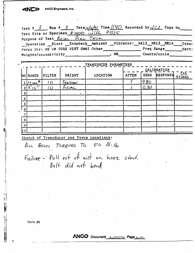
2.0 STATIC PULL TESTS
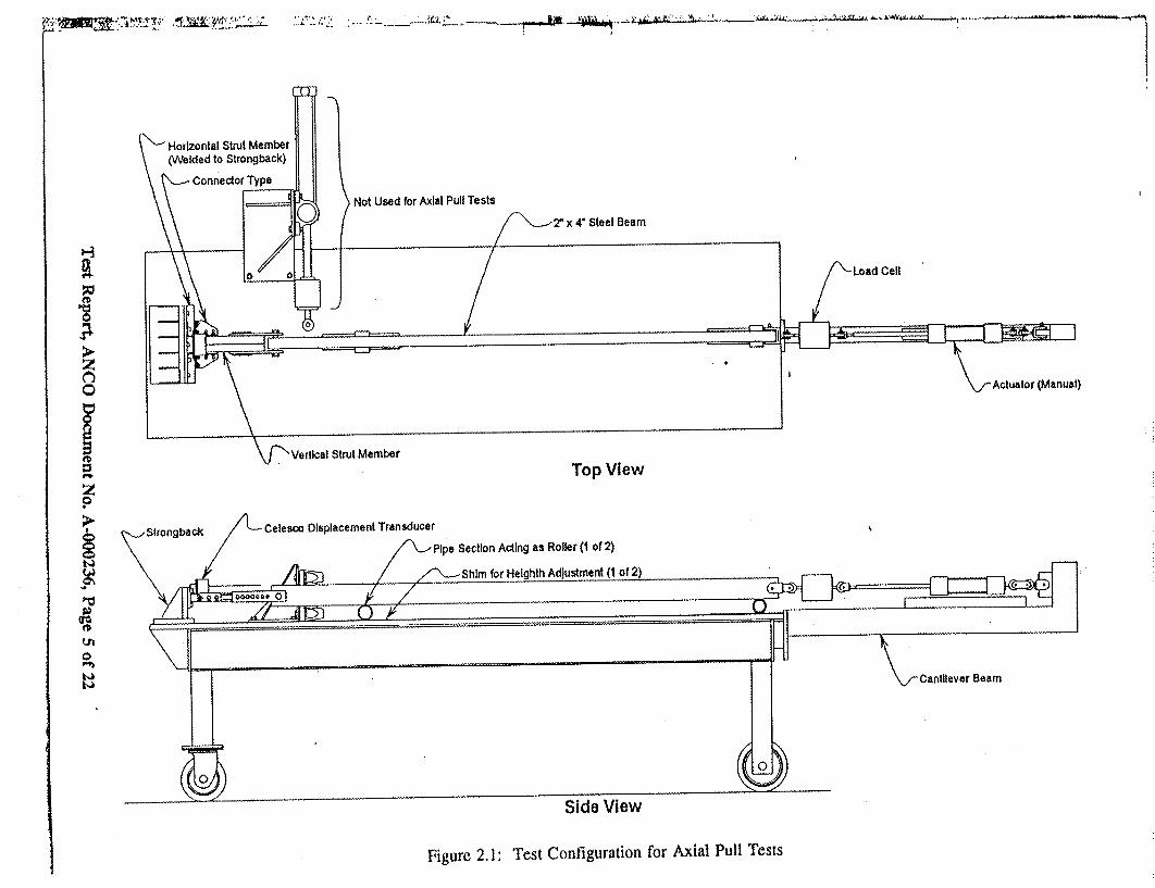
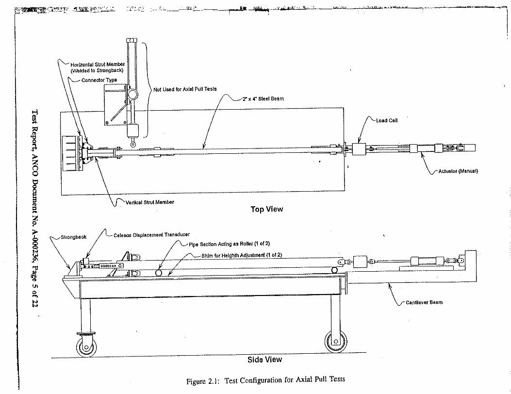
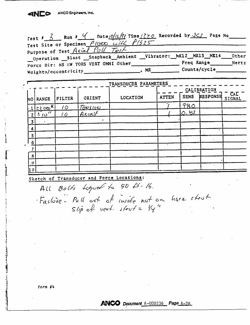
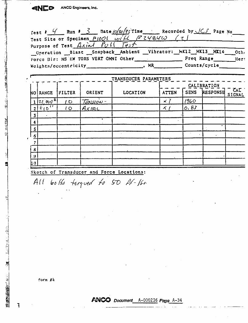
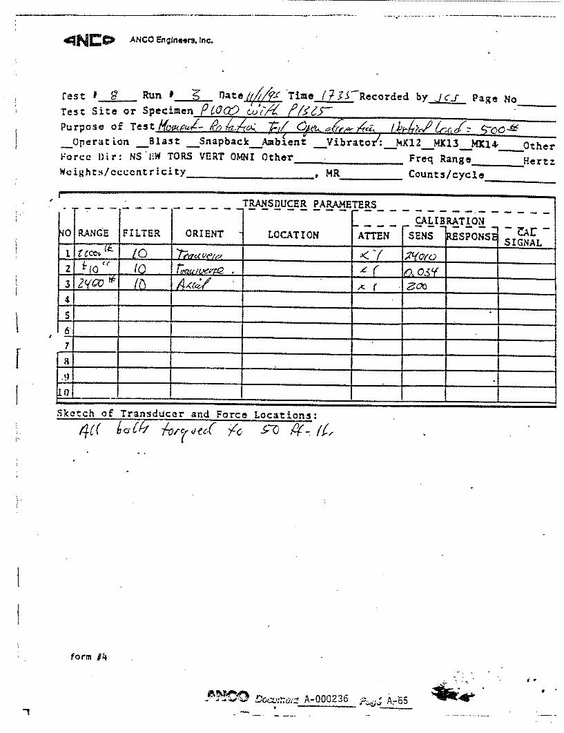
Figure 2.1 shows the test fixture for the static pull tests. Each connection was assembled
using 50 ft-lbs torque on the 1/2-inch bolts in accordance with the manufacturer's catalogue
specifications. The connection was then placed in the test fixture with one strut fixed (i.e.
welded) to a strongback to simulate the embed. The load applicator was connected to the strut
such that an axial tension simulating the vertical load of a cable tray could be applied to the
connection. A displacement transducer was connected to the strut at a distance of about 13
inches (the null position of the transducer) from the transducer mount.
Both the displacement and force transducers were electrically nulled prior to application
of any tension load. Data acqutlsition software/hardware was set up using the following
parameters:
Sampling time = 0.02 seconds
• Duration = 400 seconds minimum
- Low pass filters = 10 Hz
The data acquisition was initiated and the axial tension gradually increased in order to
minimize any dynamic loading. The force was increased until one of the following occurred:
- Joint separation exceeded 2 inches.,
• Force level did not increase with increasing displacement, or
Capacity of force cell was reached.
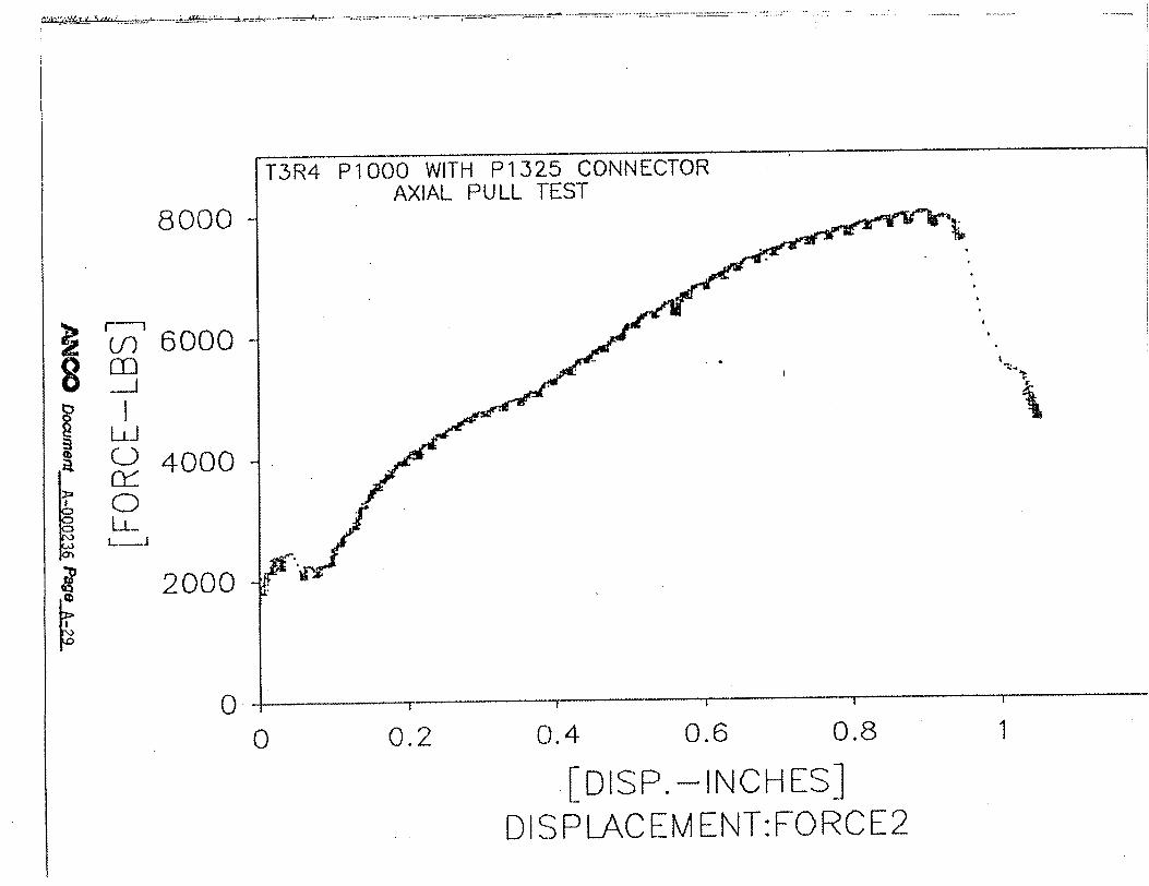
Three tests were conducted on each connection type. Additional tests were run if the
ultimate load of any one test deviated by more than 25% from the average of the three tests, up
to a maximum of six tests. The data was postprocessed to produce plots of applied load versus
displacement for each test.
Test Report, ANCO Document No. A-000236, Page 4 of 22
�- � -
"Horizontal Strut Member (Welded to Strongback)
S\- Connector Type
Not Used for Axial Pull Tests
x 4* Steel Beam
rtilcal Strut Member
Side View
Figure 2.1: Test Configuration for Axial Pull Tests
H
'5
;�m.
I z lb
Cell
0
I
('I 0
Top View
Horizontal Strut Mer (Welded to Strongbt
Connector Typ'
o
:z 0
Strongback
to
nber ack)
a}
Not Used for Axial Pull Tests
"x 4* Steel Beam
ertlcal Strut Member
SActuator (Manual)
Top View
Side View
Figure 2.1: Test Configuration for Axial Pull Tests
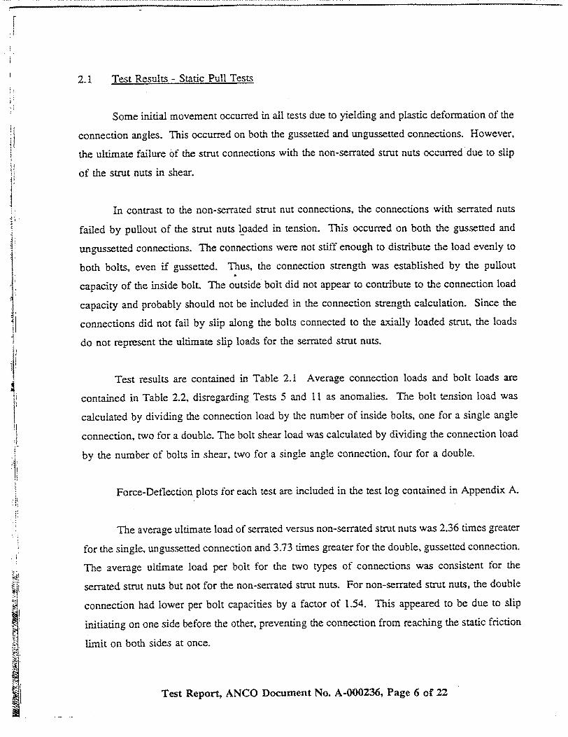
2.1 Test Results - Static Pull Tests
Some initial movement occurred in all tests due to yielding and plastic deformation of the
connection angles. This occurred on both the gussetted and ungussetted connections. However,
the ultimate failure of the strut connections with the non-serrated strut nuts occurred due to slip
of the strut nuts in shear.
In contrast to the non-serrated strut nut connections, the connections with serrated nuts
failed by pullout of the strut nuts loaded in tension. This occurred on both the gussetted and
ungussetted connections. The connections were not stiff enough to distribute the load evenly to
both bolts, even if gussetted. Thus, the connection strength was established by the pullout
capacity of the inside bolt. The outside bolt did not appear to contribute to the connection load
capacity and probably should not be included in the connection strength calculation. Since the
connections did not fail by slip along the bolts connected to the axially loaded strut, the loads
do not represent the ultimate slip loads for the serrated strut nuts.
Test results are contained in Table 2.1 Average connection loads and bolt loads are
contained in Table 2.2, disregarding Tests 5 and 11 as anomalies. The bolt tension load was
calculated by dividing the connection load by the number of inside bolts, one for a single angle
connection, two for a double. The bolt shear load was calculated by dividing the connection load
by the number of bolts in shear, two for a single angle connection, four for a double.
Force-Deflection plots for each test are included in the test log contained in Appendix A.
The average ultimate load of serrated versus non-serrated strut nuts was 2.36 times greater
for the single, ungussetted connection and 3.73 times greater for the double, gussetted connection.
The average ultimate load per bolt for the two types of connections was consistent for the
serrated strut nuts but not for the non-serrated strut nuts. For non-serrated strut nuts, the double
connection had lower per bolt capacities by a factor of 1.54. This appeared to be due to slip
initiating on one side before the other, preventing the connection from reaching the static friction
limit on both sides at once.
Test Report, ANCO Document No. A-000236, Page 6 of 22

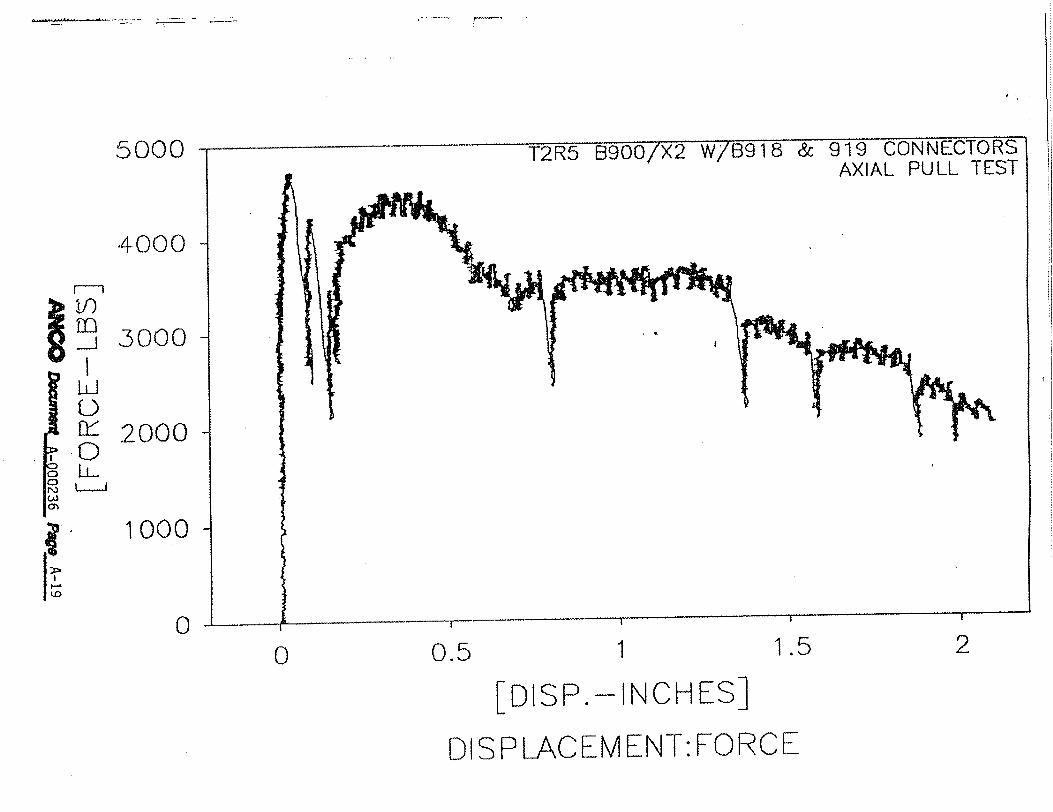
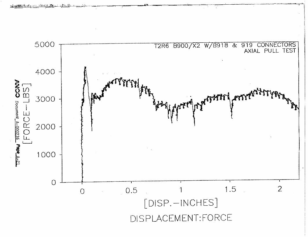
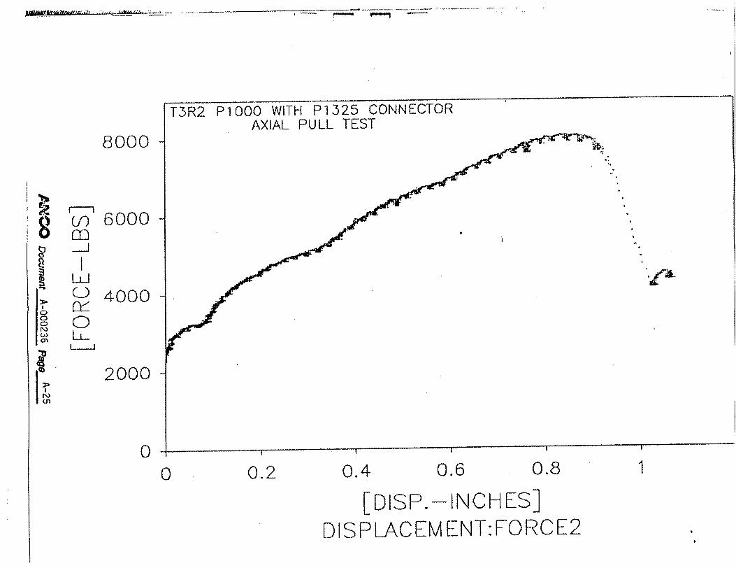
TABLE 2.1: AXIAL PULL TEST RESULTS
Connection Strut Nut Maximum
Test Type Type Load (lbs)
1 S NS 3200
2 S NS 3800
3 S NS 3500
4 S NS 3000
5 D NS 2300
6 D NS 4100
7 D NS 4800
8 D NS 4100
9 D NS 4700
10 D NS 4200
11 S S 5100
12 S S 8100
13 S S 7800
14 S S 8000
15 D S 15000
16 D S 17000
17 D S 17000
S: single NS: non-serrated D: double S: serrated
TABLE 2.2: AVERAGE CONNECTION LOADS AND BOLT LOADS
Average Load Tension/Bolt Shear/Bolt Connection Strut Nut (lbs) (lbs) (lbs)
Single, Ungussetted Non-serrated 3375 3375 1688
Single, Ungussetted Serrated 7967 7967 3983
Double, Gussetted Non-serrated 4380 2190 1095
Double, Gussetted Serrated 16333 8167 4083
Test Report, ANCO Document No. A-000236, Page 7 of 22
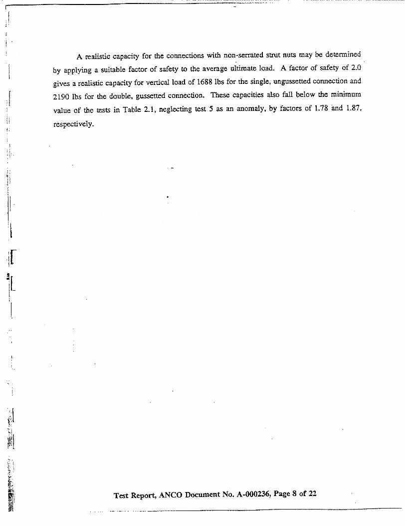
A realistic capacity for the connections with non-serrated strut nuts may be determined
by applying a suitable factor of safety to the average ultimate load. A factor of safety of 2.0
gives a realistic capacity for vertical load of 1688 lbs for the single, ungussetted connection and
2190 lbs for the double, gussetted connection. These capacities also fall below the minimum
value of the tests in Table 2.1, neglecting test 5 as an anomaly, by factors of 1.78 and 1.87,
respectively.
Test Report, ANCO Document No. A-000236, Page 8 of 22

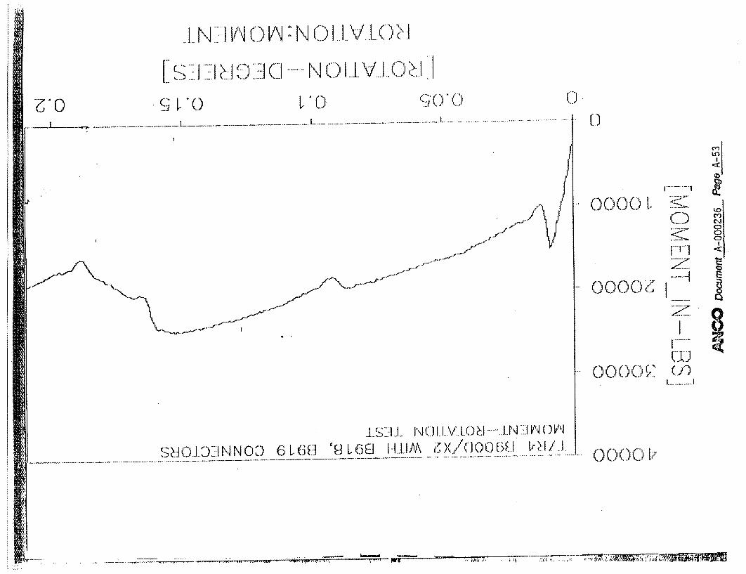
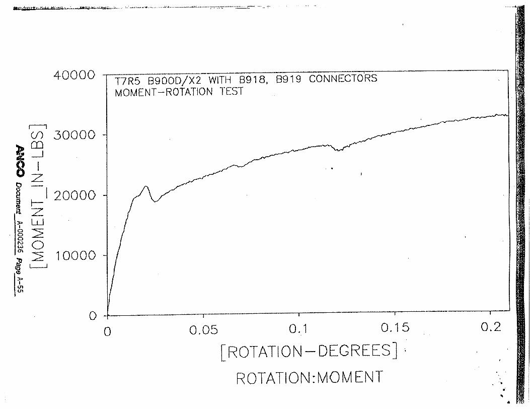
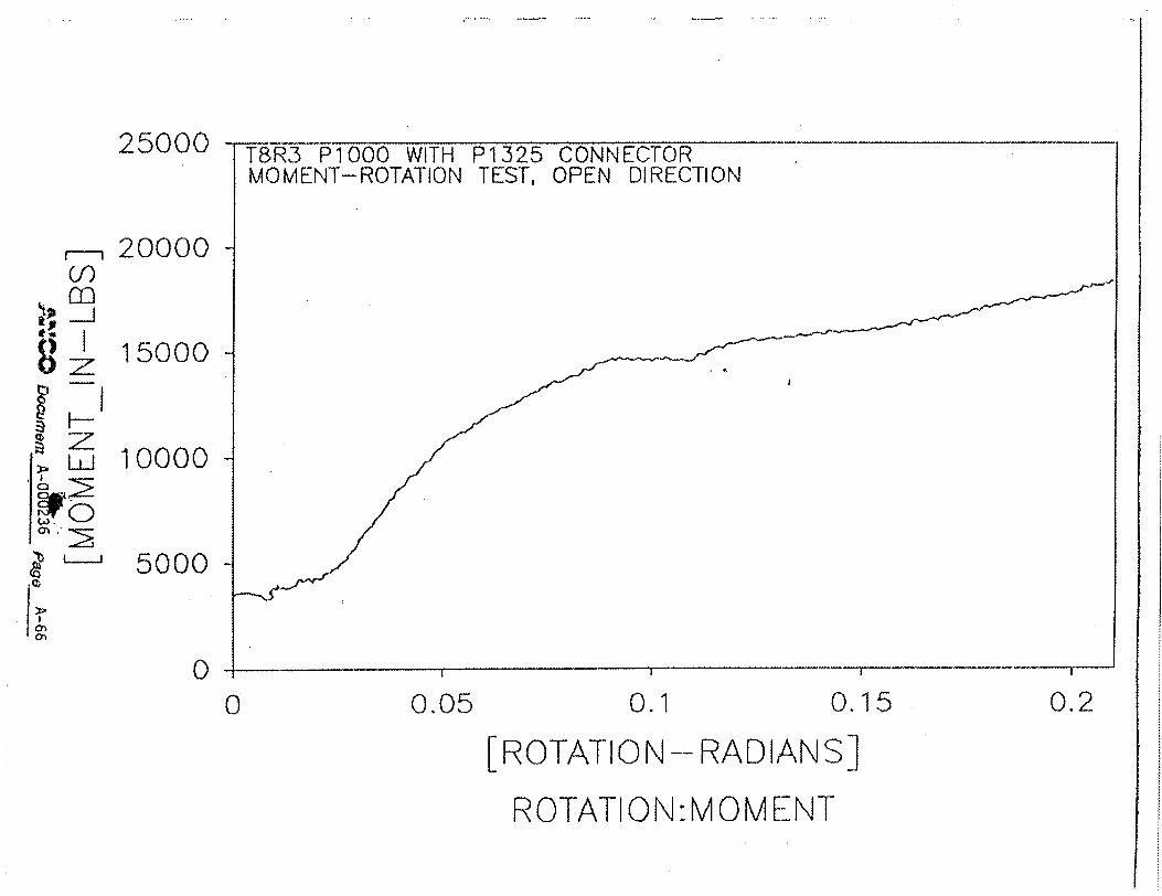
3.0 MOMENT TESTS
Moment-rotation tests were conducted to simulate forces induced by lateral loads on
flexible tray supports. The test setup is shown in Figure 3.1. Each connection type was
assembled and placed in the test fixture as in the static tension tests. A load applicator was
connected to the strut such that a transverse load could be applied. The displacement transducer
was connected to the strut so as to measure the transverse displacement, enabling calculation of
the connection rotation.
To simulate the dead weight of the cable system, an axial tension force was applied to
the strut. In order to minimize the geometric effect as the force vector changed with transverse
movement of the strut, the load was applied via a long cable. To further maintain constant load,
springs were placed in the load path.
Both the displacement and force transducers were electrically nulled prior to application
of loads. Data acquisition softwarelhardware was set up using the following parameters:
" Sampling time = 0.02 seconds
"* Duration = 400 seconds minimum
"• Low pass filter = 10 Hz
The data acquisition was initiated and the bending moment gradually increased in order
to minimize any dynamic loading. The tests were continued until. the actuator stroke limit,
corresponding to a rotation of 0.21 radians, was reached.
A minimum of three tests were performed on each connection type. Additional tests were
run if the ultimate load of any one test deviated by more than 25% from the average of the three
tests, up to a maximum of six tests. Both non-serrated and serrated strut nut connections were
tested for comparison purposes. The data was post-processed to obtain moment-rotation
("backbone") curves that show the connection stiffness and strength.
Test Report, ANCO Document No. A-000236, Page 9 of 22

H
•z
;am.
£•
0 0
Side View
Figure 3.1: Test Configuration for Moment Rotation Tests (without Limit Switches)

H
•z
;am.
£•
0 0
Side View
Figure 3.1: Test Configuration for Moment Rotation Tests (without Limit Switches)

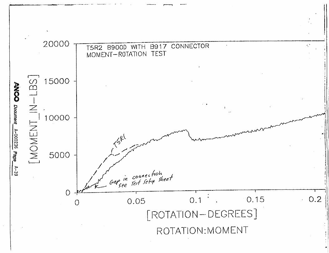
3.1 Test Results - Moment Tests
The connections initially yielded due to plastic deformation of the connection angle rather
than slip or pull-out of the bolts. As rotation increased, the strut with non-serrated strut nuts
pivoted about the compression edge, and eventually the connection bolts on the tension side
either slipped or pulled out. The strut with serrated strut nuts continued rotating without slip or
pullout of the strut nuts, exhibiting plastic hinge behavior.
Test results are contained in Table 3.1. The average moments are contained in Table 3.2.
In computing the average moments, Tests 4,9, and 10 were labeled anomalies, due to their large
deviation from the average, and were disregarded. The average bolt load was calculated based
on a moment arm equal to the strut width (1-5/8 inches for single strut, 3-1/4 inches for double
strut) and resistance by one bolt for tension or two bolts for shear. The force due to the static
axial load was conservatively neglected.
In this series of tests, the non-serrated strut nut forces were consistent while the serrated
strut nut connections were not. This appeared to be because the gusset in the gussetted
connection supplied for the strut with non-serrated strut nuts was thinner than that of the
gussetted connection with the serrated strut nuts. The non-serrated strut nut connection on the
compression side of the double strut did not provide moment resistance after yielding, while the
serrated strut nut connection did, resulting in higher moment capacity. The per bolt load
capacities calculated from these test data were significantly higher than those calculated from the
axial pull test data.
The static axial pull and moment-rotation tests showed that the connections with non
serrated strut nuts had significantly lower capacity than those with serrated nuts. Thus,
plant-specific capacities should be used for connections with non-serrated nuts. The axial pull
tests showed significant variation between single and double connections for the non-serrated
strut nuts while the serrated strut nuts were very consistent. The moment-rotation tests gave
more consistent results for the non-serrated strut nut connections but less consistent for the
serrated strut nut connections. The connections showed higher strut nut capacities under moment
loading than direct tension loading. Since the support systems in question rely on direct tension
Test Report, ANCO Document No. A-000236, Page 11 of 22
3 ..... .. . .

on the connection rather than moment resistance, it was judged best to base the allowable loads
on the axial pull test results.
Test Report, ANCO Document No. A-000236, Page 12 of 22
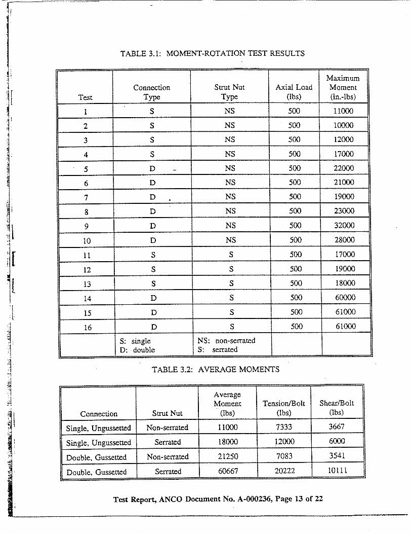
TABLE 3.1: MOMENT
[
I
Test Report, ANCO Document No. A-000236, Page 13 of 22
Maximum
Connection Strut Nut Axial Load Moment Test Type Type (lbs) (in.-lbs)
1 S NS 500 1 1000
2 S NS 500 10000
3 S NS 500 12000
4 S NS 500 17000
5 D - NS 500 22000
6 D NS 500 21000
7 D NS 500 19000
8 D NS 500 23000
9 D NS 500 32000
10 D NS 500 28000
11 S S 500 17000
12 S S 500 19000
13 S S 500 18000
14 D S 500 60000
15 D S 500 61000
16 D S 500 61000
S: single NS: non-serrated D: double S: serrated
TABLE 3.2: AVERAGE MOMENTS
Average Moment Tension[Bolt Shear/Bolt
Connection Strut Nut (Ibs) (tbs) (Ibs)
Single, Ungussetted Non-serrated 11000 7333 3667
Single, Ungussetted Serrated 18000 12000 6000
Double, Gussetted Non-serrated 21250 7083 3541
Double, Gussetted Serrated 60667 20222 10111
"-ROTATION TEST RESULTS

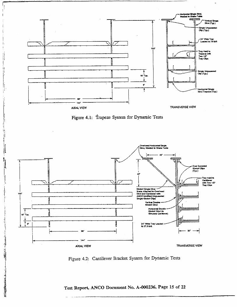
4.0 DYNAMIC TESTS
Two single span, four tier cable raceway systems were constructed on the ANCO R-4
planar triaxial shake table. One system was a four tier trapeze system with single strut supports
suspended on ungussetted angle connections with two bolts per leg, as shown in Figure 4.1. The
other system was a four tier cantilever bracket system with back-to-back strut suspended on
gussetted angle connections with two bolts per leg, as shown in Figure 4.2. The cantilever
bracket supports were braced with a single strut connected by 45-degree angle connectors with
two bolts per leg. All bolts had non-serrated strut nuts. The cantilever brackets were simulated
by strut as shown. The cable tray was standard 4-inch by 24-inch ladder type tray. The trays
were filled with electrical cables in pre-weighed bundles. The trapeze system was filled to 75
lb/ft. (6-inch fill) and the cantilever bracket system to 37.5 lb/ft. (3-inch fill).
The shake table was configured to produce coupled (dependent) transverse and vertical
input. Two biaxial accelerometers were attached to the shake table to record the test motion.
The shake table simulated a 30-second duration, wide band seismic event (following the
guidelines of IEEE 344-1987 for seismic motion) enveloping the SSE ground response for the
power plant sites. The vertical input was equal to, and in phase with, the horizontal input. The
test was initially run with a peak table acceleration of about 0.2 g, then repeated at higher levels
until failure of the tray system. Response spectrum plots from the final successful test for each
system are shown in Figures 4.3 and 4.4.
The trapeze system carried a total load of 3600 lbs, giving connection loads of 900 lbs.
The normal design capacity of this connection using the manufacturer's recommended bolt
capacities would be 800 lbs. Under the earthquake loading, the system exhibited very large
lateral displacements. It survived four tests with increasing input levels. The response spectrum
for the fourth test is shown in Figure 4.3. During the next test, with 25% higher input, the
system came loose from its ceiling connections and fell.
The response spectrum in Figure 4.3 has a peak spectral acceleration of about 3.0 g and
zero period acceleration(ZPA) of about 1.0 g. The system had a very low lateral frequency and
was not sensitive to the horizontal input. However, the vertical input was equal to the horizontal
Test Report, ANCO Document No. A-000236, Page 14 of 22
IJ
t IS" Typ.
U
6
U'.
II r
2AXIAL ViEW TRANSVERSE VEW
Figure 4.1: trapeze System for Dynamic Tests
AXLAL VIEW TRNSV•RSE VIEW
Figure 4.2: Cantilever Bracket System for Dynamic Tests
Test Report, ANCO Document No. A-000236, Page 15 of 22
IY, I
ý/7-7

I?/CC KIN]R CABLE TEST :1 awm:l
1G.222S P E C
A C C
S
IP/CC KINDORF CABLE TEST :1 CHANIE
TRAY TESTS SPAN 12 RUN :5 DAMPING : .2502
SOUTH RACEWAY TRANSVERSE X - DIRECTION
I t p r I j It�I��I t I � I I �
•F1.R888 1.2Y-H 2 FREQUENCY - H-Z 122 .800
TRAY TESTS SPAN 12 RUN :5 DAMPING : .,529
SOUTH RACEWAY VERTICAL 2 - DIRECTION
10.2•82
.1222
.12822I I . I I I I t , I f I , I , I I - I I I , 1 - ]
1,89FR 12.QUNC 1- .HZ22 FREQUENCY - HZ
Figure 4.3: Response Spectra for Trapeze System
Test Report, ANCO Document No. A-000236, Page 16 of 22
S P E C
A C C
S
I I ? I I I I L I r I I I I I I I I I I I I 1 1 1I I n
I I

IP/CC KIhLDORF CABLE TEST :3
S 10].M
P E C
A C C I .10N9
S
.81(Q
IP/CC KIR F CABLE TEST :3 cfINAE : 2
190.0m9S P E C
A C C
I C
S
.2100
TRAY TESTS SPAN 29 RUN :1DAAMPIN G I:IR05 I
SOUTH RACEWAY TRANSVERSE X - DIRECTION
I , , , I#4 4 I I 1 , I I I I I I I I I
1. RE0 r 10.00-9 FREQUENCY~ - HZ
TRAY TESTS SPAN 20 RUN :1 DAMPING : .95,9
SOUTH RACEWAY VERTICAL Z - DIRECTION
.1999 1.U299 19.29- 2 FREQUENCY - HZ
4, 44�
192.9999
Figure 4.4: Response Spectra for Cantilever Bracket System
Test Report, ANCO Document No. A-000236, Page 17 of 22
, I.

input. Because of the wide band nature of the input, it is likely that the effective vertical
acceleration of the tray system was about 3.0 g. Thus peak loads for the connections were
900(3.0+1.0)=3600 lbs. This is approximately equal to the loads achieved in the axial pull tests.
The braced cantilever system carried a total load of 1800 lbs. The eccentricity of the
trays caused bending in the vertical strut (in fact, the vertical struts were noticeably curved under
the deadweight load). By statics, the force on the top connection of the vertical strut was 1286
lbs tension and 386 lbs shear. The normal design vertical (tension) capacity of the connection
using the manufacturer's recommended bolt capacities would be 1600 lbs, neglecting the shear
force.
This system survived eight tests, each with increasing input level, without failure. The
response spectrum from the final test is shown in Figure 4.4. The input level of this test was at
the limit of the table. An additional 300 lbs of cable was then added to each tray (1200 lbs
total). The test was repeated, and the tray system collapsed.
The response spectrum of Figure 4.4 has a peak spectral acceleration of about 6.0 g and
a ZPA of about 3.0 g. It was estimated that the lateral frequency of the system was in the 5 to
10 Hz range. Thus, its is reasonable to assume that the effective horizontal seismic acceleration
was about 4.5 g, giving a lateral seismic force per support of 900 x 4.5 = 4,050 lbs. The vertical
load on the top strut connection from this force is 6,171 lb.
The vertical input was the same as the horizontal. Assuming the same frequency range
for the vertical response of the trays, the vertical seismic force was 4,050 lb per support. This
gives a vertical load on the top strut connection of 5,787 lb. Combining the seismic forces by
SRSS and adding the deadweight force gives an estimated total vertical load of 9746 lbs. This
is more than twice the load achieved in the axial pull tests.
The dynamic tests appear to show that the connections on the braced cantilever system
exhibit much higher capacity under dynamic conditions than under static conditions. This is not
an indication that a safety factor exists under dynamic conditions. This is probably because the
force calculation used an equivalent static method with 5% damped spectra, ignoring the effect
Test Report, ANCO Document No. A-000236, Page 18 of 22
of load duration, cable friction, rapid reversal of loading, and energy loss from large
deformations. If these factors were properly accounted for, the capacity under dynamic loads
would likely be closer to those of the static load tests.
Test Report, ANCO Document No. A-000236, Page 19 of 22
2-----

5.0 DETERMINATION OF GIP FACTORS FOR NON-SERRATED STRUT NUTS
Using the results of the axial pull tests and a safety factor of 2.0 gives realistic capacities
of 1688 lbs and 2190 lbs for the single and double connections with non-serrated strut nuts. The
GIP requires a vertical capacity check of three times deadload, ignoring eccentricities, using
realistic capacities. for the trapeze system, this gives a permissible weight per strut of 563 lbs.
for the braced cantilever bracket system, it gives a weight per strut of 730 lbs, neglecting
eccentricities. The comparable dynamic test weights were 900 lbs per strut for each system.
The braced cantilever bracket system is a non-ductile system per the GIP, and a lateral
load check is required in addition to the vertical capacity check. The lateral load is determined
as either 2.0 g factored by the miximum spectral acceleration ratio of the plant SSE ground
response spectrum to the SQUG Bounding Spectrum, or as 2.5 times the ZPA of the applicable
floor response spectrum. Subtracting the vertical connection force due to dead weight of 1286
lbs from the realistic connection capacity of 2190 lbs gives 904 lbs available for lateral load.
This converts to an acceleration of 0.66 g. Using the factored 2.0 g approach and assuming the
maximum ratio occurs at the ground peak spectral acceleration gives a permissible peak ground
acceleration of about 0.26 g. Using the 2.5 times ZPA approach gives a permissible ZPA of 0.26
,, The dynamic tests greatly exceeded these levels.
Test Report, ANCO Document No. A-000236, Page 20 of 22
.............

6.0 CONCLUSIONS
The testing program reported above was developed to determine realistic capacities for
cable tray support connections with non-serrated strut nuts found at two nuclear power plants in
the USI A-46 program. Static tests were used to determine average ultimate capacities. A safety
factor of 2.0 was judged to be appropriate for realistic capacities for use with the G(P procedure
for seismic verification. Full scale dynamic tests were run on tray systems whose weight
exceeded the GI'acceptance criteria utilizing the derived capacities. The dynamic tests showed
that the striconnections with non-serrated strut nuts did not lose capacity under repeated cyclic
I l The good performance 6f these systems confirmed that the derived capacities are
appropriate for use with the GIP procedures.
Test Report, ANCO Document No. A-000236, Page 21 of 22

THIS PAGE INTENTIONALLY LEFT BLANK
Test Report, ANCO Document No. A-000236, Page 22 of 22
............ ... - ----------
APPENDIX A
TEST DATA
MACO Docnmt-a~2&. PLeA
ANGO At400 Ei�� �
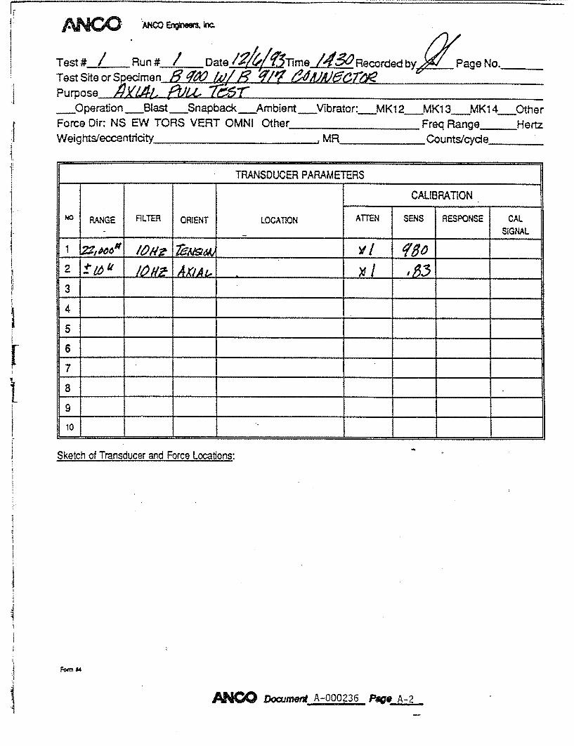
Test# / Run# i / Date ,mRecorded by/ page No. Test Site or Specimen )q /,V' Page No-%____72W Purpose /Y//41. A: 5 v5"" ___Operation _Blast __Snapback Ambient Vibrator: MK1 2_MK1 3_MKI 4__Other Force Dir: NS EW TORS VERT OMNI Other Freq Range Hertz Weights/eccentriity ....... , MR Counts/cycle
ANOW Documer, A-000236 P/t A-2
TRANSDUCER PARAMETERS
CALIBRATION
NO RANGE FILTER ORIENT LOCATION ATTEN SENS RESPONSE CAL I_ _ _ SIGNAL
2 Itzet" J¢#A .4k4 ..... __!_._
3
4
5
6
7
8
9
10
Sketch of Transducer and Force Locations:

03
C
rn
Li C-)
0 Li
z Li
0
w
LN
0
C
-2�\J Q�I � '��;
ANOODocmevt A-000 236 pV* -3
U•
ZC wJ 01 ý(-)
x
0 G~)
00 N;
0 0
r

ANCO ANCO E*MM W
Tes #. a ge No.
Tet Jfi.Run # Date/;/ 077mejlY5ecordedbPg o Test Site or Specimen. / Purpose AX1.4t." ___Operation Blast Snapback Ambient_._Vbrator: MKI 2 MK13 MK14 Other
Force Dir: NS EW TORS VERT OMNI Other Freq Range Hertz Weights/eccentdty .. MR Counts/cycle
Sketch of Transducer and Force Locations:
Fon "4
ANO Dtcumet A-OO2Z36 Pa A-4
TRANSDUCER PARAMETERS
CAUBRATION
RANGE FILTER ORIENT LOCATION ATTEN SENS RESPONSE CAL SIGNAL
1 2Zo0 /o,9,• 7• e• ,___,,,,t____
2 t1 6I', 163L L~ 3
4
6
7
8
10

40(1(.)0
3~000)
2000
1000
0C)
Ti k-2 B3900D Wil-I- 89 1 7 CQNNE-GTOP AXIAL PULL.[. TEST
C r'1 .4- 0.4-0.6 .081
L-DlSR.--INClH-ESi [I SFl LAOCFEM E NT:FO FRC E
I I 00 0
L�)
(Tf)
0

ANCJO ANCO Er*WW3, k
Test#_ Run # 3 Date.L'-L/ Time Recorded by,"i Page No._ _
Test Site or Specimen- g 91 /Ri7~ L Ne2 Purpose 77[ 3,95 r6~r
Operation Blast Snapback Ambient ___Vibrator: MK12 MK133 MK14 Other
Force Dir: NS EW TORS VERT OMNI Other Freq Range HertzWeights/eccentricity
Sketch of Transducer and Force Locatons:
Fn "4
ANC Document A-000236 P•eA-
MR Counts/cycle
TRANSDUCER PARAMETERSCAUBRATION
SRANGE FILTER ORIENT LOCATION ATTEN SENS RESPONSE CAL SIGNAL
2 ±I"10' loitAxt,& x 1 43, 3
4
5
6
7
8
9* LI0_ _ __ _ __ __ _ _ _ _

0) C 0
0-,
PNOO Document A-000236 Page J-&...
00 0
0
z z
Li
0
z
LiJ 0
w0T
C0 C)
_H a),
0 '-4'
H
I-
----- ---- -- --
)Lj

A I•J#"A~f I Uf�1�� �n*aFu Iei�*
Test# I Run # D ate /Z/Z 404 me/ O Recorded Page No. Test Site or S 'imen 6 d Purpose C
Operation Blast Snapback Ambient Vibrato r: MK1 2 MK1 3 MKI 4 Other Force Dir: NS EW TORS VERT OMNI Other Freq Range Hertz Weights/eccentricity ,MR Counts/cycde
TRANSDUCER PARAMETERS
CAUBRATION
No RANGE RLTER ORIENT LOCATION ATTEN SENS RESPONSE CAL SIGNAL
2 l j g0 ••_ _ _ x ___
3
4
6
7
8
10
Sketch of Transducer and Force Locations:
Fofn 4
ANO Document A-000236 Pag -_ _

c.OW oiL
('-3
�ICf) 0
I I
'-N
a
F J
ANOODocument A-000236 Pag
0 U LU
QU
-�
rr�
I.J
F-'
p" r',,
0
u�.
00 I-'
I
0 0
00 r'--,,

12%4 .00 A1CO EfnwM kr
Test # . Run # - Date Time Recorded by Page No. Test Site or Specimen " Purpose 11W
_Operation Blast Snapback __Ambient Force Dir: NS EW TORS VERT OMNI Other Weights/eccentricity
_Vibrator: MK12 MK13 MK14 Other Freq Range Hertz
,MR Counts/cycie
TRANSDUCER PARAMETERS
CAUBRATION
NO RANGE FLTER ORIENT LOCATION ATTEN SENS RESPONSE CAL SIGNAL
2 " 10g Ax9A3 3
4
6
7
8
9
10
Sketch of Transducer and Force Locations:
Form $4
ANCODocument -00236 Page_-_12

fWWc ANco ErqkmM W
Test Run # 1 Date X/ ftinlr/ & Recorded by Page No.___ Test Site orSpecimnen C 2 Purpose iX/14(" a t4,u., ,
Operation Blast Snapback Ambient Vibrator: MK12 MKI 3 MK14__Other Force Dir: NS EW TORS VERT OMNI Other Freq Range Hertz Weights/eccentridty . MR Counts/cycle
TRANSDUCER PARAMETERS
CAUBRATION
"" RANGE FILTER ORIENT LOCATION ATTEN SENS RESPONSE CAL SIGNAL
2 170M ,agi Axme_______, ~ __
3
4
6
7
8
9
310 _ _ __ _ __ _ _ _ _ _ _ _ __ _ _ _____
Sketch of Transducer and Force Locations:
FAN D4
ANODocument A-000236 PBQ~A• .,Q.

0.5 1 1.5 2
[DISP.-INCHES]
DIS P LAC EM ENT: FORCE
5000
4000
m
._J
LLJ U
0 LL. L, J.._
S cJ 0 C
'-I.
0 0
3000
2000
1000
00

-- - - --. - '.. V. --.. ..-- -, I
0O5 1 1.5 2
[DISP.-INCHES]
DISPLACEMENT: FORCE
45000
4000
In
Li
0 It LW--
I C) CD
3000
2000
1000
00

/%j4Q" ANCO ErhM r
Tes #...Run # 3 Date_/AM '//egMeI& - codeby Page No.___ Test Site or Specimen 4',.7 /~ fg Purpose
O__peration -Blast Snapback Ambient Vibrator: MK12 MK1 3 MKI,4 Other
Force Dir: NS EW TORS VERT OMNI Other Freq Range Hertz
Weights/eccentricity_____----- - .MR counts/cycie
______ TRANSDUCER PARAMETERS
CAUBRATION
NO RANGE FILTER ORIENT LOCATION ATTEN SENS RESPONSE CAL.
OMENTSIGNAL
2 Joho" - xk3 3
A_ __ _
4 _ _ _ _ _ ____ _ _ _ _ _ _ _ _
10
Sketch of Transducer and Force Locations:
F'xm #4
AM10 Doccument A-000236, Pag A 4

5000 T2R3 B900/X2 W/9918 &
4000
M 3000
0•2000 0
1000
0
0 O.5 1 1.
[DISP.-INCHES]
DI S P LAC EM ENT: FORCE
5 2

A NGO ANco 80ew,m r
Test# Run #___Date7 L4 % jirne /513Reco rded byz ~P age No. Test Sfte or Spe~cimen zE 19ý70 9Z y 5~f6~ ~~~
Purpose X/1 2 7?6__Operation -Blast Snapback__Ambient Force Dir: NS EW TORS VERT OMNI Other
Vibrator: MK1 2 MK1 3 MKI 4 Other Freq Range _Hertz
Weights/eccentricity, MR -counts/cydle-
Sketch of Transducer and Force Locations:
F-or."
ANCO DowmentA-Q000236 Psge A-16
______ _____ TRANSDUCER PARAMETERS
CAUBRATION
NO RANGE FILTER ORIENT LOCATION ATTEN SENS RESPONSE CAL SIGNAL
2~_r~~Ž. ~ ____
23 ~f ~
4 _____ ____
45_________
5 6 ___ _____ ____ ____________
10

-tt1iYttht2LYi� wAttL.SttXz :MT.r *t jff�t%'.�ff§twS at t�tj�jfl,�' � -'4Wt 4k)W4A A�
0-5 1 1.5 2
[DISP.-INCHES]
DISPLACEM ENT: FORCE
5000
4000
3000
2000
1000
0
m -Jd
Lu 0 yf
IoC
0

ANCOW AWCO Ef*WM r
Test# Run# DateTime //% O<iRecorded by Page No. Test Site orSpedmen 400 XO) Purpose A61 Pa gn!ýT
-Operation Blast __Snapback Ambient Vibrator: MKI12 MK13 MK14 Other
Force Dir: NS EW TORS VERT OMNI Other Freq Range Hertz
WeightsTUccentriPEty MR Counts/cycle
Sketch of Transducer and Force Locations:
Fo4 U
ANC~oax -ZZ Page 1
TRANSDUCER PARAMETERS
CAUBRATION
NO RANGE FILTER ORIENT LOCATION ATTEN SENS RESPONSE CAL SIGNAL
3 4
5
6
7
8
10
0.5 1 1.5 2
[DISP.-INCHES]
DISPLACEMENT: FORCE
5000
.4.000
m
Ld
,0 o LL.
(Si,
,5000
2000
1000
00

/.%j4W AWCO e~iMe W
Test #2~z Run # ~ Date! M// i/mej 2(IA RecordedbyPgNo___ Test Site or Specimen /f' ?W rx 111 AV d7/df 67~J//
Purpose /7 f.. /tC 714"1 ' O__Operation Blast Snapback __Ambient V___ibrator:_MK1 2 MK1 3.MK1 4 Other
Force Dir: NS EW TORS VERT OMNI Other Freq Range Hertz
Weights/eccentricity ,MR Counts/cycle
TRANSDUCER PARAMETERS
CALIBRATION
NO RANGE FILTER ORIENT LOCATION ATTEN SENS RESPONSE CAL SIGNAL
2 t/O l iAxtA. 9L ,5 3
4
5
6
7
8
9
Sketch of Transducer and Force Locatons:
cm4
'I _____ - X=wCi3 Document A-000236 Page A-20
kk� � �
0.5 1 1.5 2
[DISP.-INCHES]
DIS PLACEMENT: FORCE
5000
4000
_J
w t)
0 LL
,3000
2000
8 C C
Cb -4
0 0 0
I 1000
00

4N~~ ANCO Engtn**Ms In-c.
res t.... Rn .......... fat e IV, Time../L;00. Recorded by-J( PgeN
Test Site or Specimen A1F6070 v_'-l" Purpose of Test aqxLZY ELL 7;:v/(__Operation _Blast __Snapback__Ambient __Vibrator: MK1Z__MX13__MX14. Other
Forcc Dir: NSI:W.TORS VERT OMNI Other__ Freq Range 4- Hert:
Weightsl/ccentricity , MR Counts/cycle
-TRANSDUCER PARAMETERS_ CALIBRATION
0 RANGE FILTER ORIENT LOCATION ATTEN SENS RSPONSE SNAL ___ ___ ___ ___ __ ___ __ ___ ___ ___ SIGNAL ,
31 4
5
6'
-7
I. 7101 ,, '_ __ __ _ __ ..J... .2 Q. __ _ __,
Sket:ch of Transducer and Force Locations: 2 ( ocm " ,I A__ueo To gQ-0_ _
L e- o cc..z
Ce ('e C>
Vaui" ( ( * # J
form 44
j:,4-4O Docwjfleft__A-Q00236- Page.A--Z
J
ý 6 r ; - -ý 4-ý/-,

1-5000
--4-000
-3000
--2000
m
Cf)
~LL
0
[DISR.-INCHES]
DISRLACEMENT:FOHCE2
--1000
0o.2 0.4 0.6

4414COANCO Enginbrs. InC.
rest I ; Run , D fat e 0 Time J2 Recorded by2C Pag No..
Test Site or Specimen P/100 cv(A P1 -Purpose of Test xL i9 .- ?;__Operaton Blast _Snapback__Ambient -Vibrator:__MK1ZMK13__MX14- Other
'orcc Dir: NS[.W.TORS VERT 04NI Other _______Freq Range Hertz
Wcights/cccentricity , MR Counts/cycle
TRANSDUCER PARAMETERS
- CALIBRATION R0 ANGE FILTER ORIENT LOCATION ATTEN SENS RESPONSE SIGNAL
4,,
7
__ __ __ __ ___.... ...... 0 ~ _ __ _ __ _
Sketch of Transducer and Force Locations:
4______ __________ _____? _____ A(___
ýact~ Olri( to~ 4 cý' go (- e
,,,-0 kok-f. s-7,,W
form 44
ADocument A-000236 Page A-24
-------- ------- -- -
T3R2 P1 )0 WITH P1325 CONNECTOR AXIAL PULL TEST
0.2 0.4 0.6 0.8
[DISP.-INCHES] DISPLACEM EINT:FORCE2
8000
6000
4000
m
0 LL
L-J
cS
2000
00
1
0
4qNC: ANCO Engign**Ms.
rest tu n I'atei Time /(.O. Recorded byZ-/J Page to
Test Site or Spec imenL P eo.
Purpose of Test -4X. PuLL= 1?,TY-7
__Operation -Blast _ Snapback__Ambient -Vibrator: .MKIZ__MK13__MX4- Other
Forcec )ir: NStiW TORS VERT OMNI Other Freq Range Hertz
Wcights/ccccntricity , MR Counts/cycle
--- TRANSDUCER PARAMETERS
CALIBRATION
O RANGE FILTER ORIENT LOCATION ATTEN SENS kSPONSE - -A
____ __ ___ ___ _ __ ___ ___ ___ _ __ ___ ___ ___ SIGNAL
1'Z 4xi (0 go z b kI 0~L ' - ............ _. I :.O0 __ __ __ _
4
7
3 ____0 ___
4{" _ _ _ _ _ _ _ _ _ _i , . ¢
S ____r_ __ ___ __ ...... . ..... ... ..._____ __ __ __ __
Sketch of Transducer and Force
A ( , o ..r=z
S-&
Touo,.., T7b
Locations: -o
koc-t. !;4-u/
form 14
D~ocument ~j~a=5 Pae A-1
PC, t ( W ,,u ý ( 0Ld 6 , d6(f c ýC4 ýetAe
I

- I
T3R3 P1000 WITH P1325 CONNECTOR AXIAL PULL TEST
8000
c- 6000
U 4000
0
2000
0 I I I
0 0.2 0.4 0.6 0.8
[DISP.-INCH ES] DISPLACEM ENT:KFORCE2
1
4qNr:C! ANCO Eng.*4rM InC.
r6 Recorded by jcL. Page No
Test Site or Specimen P(Co cw.AC 2
Purpose of Test xfc Po7 7-,,,
__operation _Blast __Snapback Ambient __Vibrator: 4KIZ__-M 13 .MX• . Other
Forcc 1)ir: NSr:W TORS VERT O0NI Other Freq Range Hertz
Wcight./ccecnt ricity ._ MR Counts/cycle
---- TRANSDUCER PARAMETERS
" -.... CALIBRATION '
o RANGE FILTER ORIENT LOCATION ATTEN SENS ESPONSE SIGNAL
-
S 6'
Sketch of Transducer and Force Locations:
�V�( I5Q6• A�,e/�4
gi 4 �-f
!-D 4,- /4.
(cAd(e4� � (:3 '�..
form #4
AN O Dcmnt A-000236 Pae L-2&
ýL 6 r t . r ý/_rl U ý_
8000
6000
4000 -
2000
0
T3R4 P1000 WITH P1325 CONNECTOR AXIAL PULL TEST
I I I
0.2 0.4 0.6 0.8 1
[DISP.-INCHES] DISPLACEMENT:FORCE2
S U,
r1uO
LiJ C-)
0 LL L.-J
I

44NE~p ANCO Ezgn..rs.3 Inc.
rest 'L.. Run 'L..,.fate 14 Time1(/ Recorded by "I C Page No
Test 5ite or Speci~men '(00( ( L"-" 2~~- LO ) -
Purpose of Test Are'c IDQ( Zef --operation -Blast __Snapback__Ambient -Vibrator: MXIZ-MX13 MX14 Othe:
1Forcc iDir: NS I:W' TORS VERT OMNI Other_________ Freq Range -Hert
Weights/ccicentricity MR_____ Counts/cycle_____
-- _TRANSDUCER PARAMETERS_
CALIBRA~TION rAI NO RAGE FILTER ORIENT LOCATION ATTEN_ SES SPONSqSGA
2_ i __0 (& __ _ __ _ ___ _
3~ C ______.L ________
4 _ _ __ _ _ _ _ _
4 _________ ____
7 ____ ___________
6 10 __ _____
Sketch of Transducer and Force Locations:
4( Ui ec/ v4-~. 4c4 - (Of zq5YW q0)(e
Uelr Lo#il CLt
r_0k(Ut t~CAfL. It~ f,('~ quk O
form Il4
A?=O Dacmer#t A-000ý236 Page A-30
4.
I
e(e(oýY-o
,.,- r-1 -- I

0
00 0.4 0.6 0.8
[DISPK-INCHES] DIS PLACEM ENT:FORCE2
15000
10000
5000
._J
Lii 0
0 LJI..z_
0 0 0
1%0.2

44NJ:C~ ANCO Emgfn**ms Inc.
rest iJ jRun 1Z_ Dlate I ~Time MOO Recorded byj,ý Page No
Test Site or Specimen ,4/6701 ~-/ cy 1'6() (z
Pu rpo se o f Tes3tAt I'Wv -4/4. 1 /' &. __Operation __Blast __Snapback _Ambient -_Vibrator: _MKI2__MKI3_ MXl4__Othe:
I:orcc 0ir: NSI-.W TORS VERT OMNI Other_ _ _ _ Freq Range Hert:
Weights/ccccntricitY_, MR Counts/cycle
-- TRANSDUCER PARAMETERS
CALIBRATION
o RANGE FILTER ORIENT LOCATION ATTEN SENS SPONS -_ ______ _ __ _SIGNAL
~~" t2 7 I
,4
7 S__ ___ ___ _
Sketch of Transducer and Force Locations:
Y.i )e A., kca, I,,,/... itC_,f 4 ::.C
form #4
N Document A-000236 Page A-32
41

N 0
0 0.2 0.4 0.6 0.8
[DISP.-INCHES] DISPLACEMENT:FORCE2
15000
10000
5000
0
SLJ
0
0 LL
4NC) ANCO Engln..rIc
rest L Run f3 Date c to ?YTime___ Recorded by.C Page No
Test Site or Specimen P10c9( Lv(,iQ F-"z'fc1A2 (z Purpose of Test iaAo..-t P(-(-- RU Tý(I __.OperatLon _Blast _Snapback._Ambient -Vibrato r:__MK1 Z_MK13 M_14- Oth,
Forcc D1ir: NSI•W TORS VERT OMNI Other Freq Range Here
Wcights/ccccntricity_., MR Counts/cycle
TRANSDUCER PARAMETERS
CALIBRATION
O RANGE FILTER ORIENT LOCATION ATTEN SENS RESPONSE SIGNAL Sý C)NA
4 , ,
7
Sketch of Transduicer and Force Locations:
4(( &ob•i 471 I
form 44
ANGO Dowmernt A-000236 Page A-34
I

15000
10000
5000
00.4 0.6 0.81
[DISP.-INCHES] DIS PLAC EM ENT: FORCE2
m
o0 (I
0 0 0• W..__
Lo
0 0.2

Test# • Run #J.ZDatejL ie/6S Recorded by ZPage No.___ Test Site or Specimnen 2q ¾'D < 9 ~Jw Purpose P4)!6V r,4 7r1 M/~ 725' &Z '2/41 eO4 V ~6Vc O Aac
Operation _Blast Snpak Ambient Vibrator: MKI 2 MK13 1_/_K14 Other Force Din: NS EW TORS VERT OMNI Other Freq Range Hertz Weights/eccentricity, MR Countstcycie
Sketch of Transducer and Force Locations:
In/f 40", Q6�</4 ,.ýo'41- t1-z(A
Co, 1.q& 6-C k00*eCr/ ecJ(6+~a
A=DOcument A-00-0236Pae -
_____ ____ TRANSDUCER PARAMETFERS
CAUBRA110N
NO RANGE FILTER ORIENT LOCATION ATTEN SENS -RESPONSE CAL SIGNAL
1 z Od /Ot/g Vw_ _ __ _ _ _ .½9 _ _ _ _ _
2 0/ ' ý6/ 3AJS _ _ _ __ C . 1 _ _ _ _
3 Z e 6i~7V' _ _ _ _ _ _J L _ _
4 _ _ _ _ _ _ _ _ _ _ _ _ _ _ _ _ _ _ _ _ _ _
5 ________
10
Fvn $4
lei 74e.'e-7Z ýC-, 24 416

20000
15000
10000
5000
0
0
T5R1 B90OD WI1H MOM ENT-ROTATION
0.05
B91 S TEST (JUNHWI UK
.0.1
[ROTATIO N- DEGREES]
ROTATION-MOMENT
B I 10I,
cm
-_J
H
LiJ
0
L •...J
0.15 0.2
'10,vo

ANCO ANCO Enps-
Test ~ Rn# Z Date _t't Umj Recorded byJf ý,6Cpage No.___ Test Site orSpecimen /,' c2 vgýC1- 4
Purpose ge5Lo-&041r04/ A//o4V7- 5' '
__Operation Blast Snapback f~mbiernt Viibrator:-MK12_/Mkl 3-MK14__ter Force Dir: NS EW TORS VERT 0MNI Other Freq Range____Hertz Weights/eccentricity .MR counts/cycle
TRANSDUCER PARAMETERS
CAUBRATION
S RANGE FILTER ORIENT LOCATIONt ATTEN SENS RESPONSE CAL ____ ___ ____ ___ ____ ___ ____ ___ ___SIGNAL.
2 ¾c< (0 o a L x~L o0,vY3 (Cc9 ~ (6 0ý •J(o4 __ _ _ __ _ _ 1 La ___ _
4 _ _ _ _ ____
5 _ _ _ _ _ _ _ _ ____ _ _ _ _ _ _ _ _ _ _ _ _ _ _ _____ _____
6 _ _ _ _ _____ ____ _ _ _ ______
7 ____ _ _ _ _ _ _ _ _ _ _ _
8 _ _ _ _ _ _ _ _ _ _ _ _ _ _ _ _ _ _ _ _ _ _ _ _ _ _ _ _ _ _ _ _ _ _ _
9 _ _ _ _ _ _ _ _ _ _ _ _ _ _ _ _ _ _ _ _ _ _ _ _ _
10
Sketch of Transducer and Force Locations:
4 ~ 00 4ý,z 4-/K If47 4LeIf(~A~ ~1 Q iRp'
eL~ ~KY ~ 17
ANWDocment A-uzaiPagqoA-38
8< C))
0 o .... _
(0
20000
15000
10000
5000
0
[ROTATION-- DEGREES]
ROTATION-MOMENT

20000
15000
10000
5000
O-
T5R2 B900D WITH MOMENT- ROTATION
0.050
B917 CONNECTOR TEST
0.1
[ROTATION - DEGOREES]
ROTATIONMOMENT
-.J
F-
0
I 0
0
CD
CD
I I
0.15 0.2

/ANOC ANCO Erqkvs, W-~
Test #. _ Run # L._ Date.L• 1.l 19-3TimeL,ý•Eý5 Recorded byJ•,ii'age No.___ Test Site or Specimenfe ?00 ( -ý - _",-7ýýc fe " Purpose eoY 1f 4 9 ,AC• rz/ c'
___Operation -Blast ___Snapback ýrmbtent V__ibrator:_/MK1 2__MK1 3 MK14 -Other
Force Dir: NS EW TORS VERT OMNI Other Freq Range Hertz
Weights/eccentridt .MR Counts/cydle
TRANSDUCER PARAMETERS
CALIBRATION
NO RANGE FiLTR ORIENT LOCATIN ATTEN SENS RESPONSE CAL I - SIGNAL
2 r 0jf~
3 ___.14 . ____ _
4 _ _ _ _ _ _ _ _ _ _ _ _ _ _ _ _ _ _ _ _ _ _ _ _ _ _ _ _ _ _
5 _ _ _ _ _ _ _ _ _ _ _ _ _ _ _ _ _ _ _ _ _ __ _ _ _ _ _ _ _ _ _____
I E0
S ketch of Transducer and Force Locafions:
/21 ~5-0o4/4a.
IV < 4;6 �A�7 (e �e'�-7 A! 616 C�c,&
Fum" £
ANCO Doaimer1t 2--U-02-16 Page A-41
4 ff ý 0 11ý/,/ 1C., -e all",

20000
15000
10000
5000
0
0
T5R3 B900D WITH MOM ENT- ROTATI ON
0.05
B917 TEST
CONNECTOR
0.1
[ROTATION- DEGREES]
ROTATIONMOMENT
m __j
0
�1
I) cri~
0.15 0.2
a*G AJNCO nEf**9 b
Test 5~Run #__5(_ Date 2 J Time Recorded by.P g o___
Test Site or SpecimnQf 9eOt S- & /7 (ceqkee r
Purpose /YhaV,-/- A;' 74cA-1 b C),e' 71lc4e'.l' t,~ 1frepce ('- tvotv
Operation -Blast S__napback Ambient V__ibrator:__tAK12 M1 K4_te
Force Din NS EW TORS VERT OMNI Other Freq Range Hertz
Weightsleccntricity-- ------- , ~MR -- O -ounts/cyde
TRANSDUCER PARAMETERS
CALIBRATION
NO RANGE FILTE ORIENT LOCATION ATTEN SENS RESPONSE CAL
SIGNAL
2 C) 7'c ___0_0;q
3 2 cfc,- .0 (0 zoo__ _ ___ __
4 _ _ _ _ __ _ _ _ _ _ _ _ _ _ _ _ _ _ _ _ _ _ _
5 _ _ _ _ _ _ _ _ _ _ _ _ _ _ _ _ _ _ _ _ _
10
Sketch of Transducer and Force Locabons:
,4(( Lo Aj jL le
66 Cf- k e C
/0 !;o'0
/1O 0AZ~C S
cC) (d�Ce A-
I~oo DoumentQpO236 Pn
Fom

20000
15000
10000
5O00
00 0.05 0.1 0.15
[ROTATION - DEGREES]
ROTATION:MOMENT
-j
•-7
0 LW
0.2

-1200
-1000
-800
-600
-400
-200
00
T5R4 B900D WITH B917 CONNECTOR MOMENT-ROTATION TEST
--I
0.05
0 0.1
[ROTATION -DEGREES]
ROTATION:AXIAL LOAD
__1 I -LJ
Lii 0
LI.
0.15 0.2I

AMCAO 8*8 r
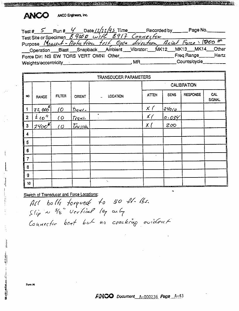
TetRun #_I _ Date /X/ 9 ~ime 6k7• Re~corded by Page No.___ Test Site or'Specimen 60 1"l,&1al 111 ' P urpose AM MAL /- -ý2
Operation Stast Snapback Amrbient Vfibrator: MK1 2 MK1 3-MK1 4 Other
Force Dir: NS EW TORS VERT OMNI Other, Freq Range Hertz Weights/eccntricity MR Counts/cydie
______ TRANSDUCER PARAMETERS
CAUBRATION
NO RAN4GE FiLTER ORIENT - LOCATION ATTEN SENS RESPONSE CAL
SIGNAL _ _ _ _ _ _ X /
2~4 69 ~gVx k ____
23 /" 9' 7&t'VA s L 6, 5)'___ _
4 6/?7'~ _ _ _ _ _ _ z . '6 _ _
5 ___ ____________ ____
6 ____ _____________ __________
10
Sketch of Transducer atd Force Locations:
<L/(� Cc k1e�4
1I ��u�2(�< 4-�It 67 a:: 7/7gjie c c f4 & A~ i6Aud� �
WeQ4,4"
,0:4NCO Docmerd A-000236 pace A-46
.Vol (/ 61 I
Fani U

4.0000 -i
T7RI B900D/X2 WITH B918, B919 CONNECTORS MOMENT- ROTATION TEST
,30000
20000
10000
00
___________
I
0.2
[IROTATION- DEGREES]
ROTATION:MOMENT
r1-(J)
m -- 7
--7
t ii 0Z
0,05 0.1 0.15
N -.4
.4.
0.2
ANCO ANGO Ef*WM I=c
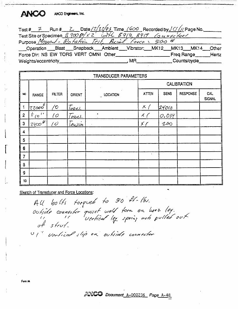
Test#LRun # Z- Date/Z/t4414 S Time (COO RecordedbyjJC iPageNo. Test Sfteor'Specimen (L~~ J~<K t '/Qi?~ co~/r
Purpose /Yon -6~A~4-~ ~I ~t Operation Blast Snapback Ambient Vibrator: MKI 2 MKI 3 MKl 4 Other
Force Dir: NS EW TORS VERT OMNI Other Freq Range _HertzWeights/eccenthidty MR Counts/cycle
Sketch of Transducer and Force Locabons:
60i%
v ( " elO , 'rtll- a- ,. C 4A ea,
Fwm 04
DomentA-000236 Pagtq A-48
TRANSDUCER PARAMETIERS
CALIBRATION
NO RANGE FILTER ORIENT -LOCATION ATTEN SENS RESPONSE CAL SIGNAL
2 (0' (C 0, 0So ' __
3 -Z__ (ýc (z6) ____ _ _ __
4 _ _ _ _ _ _ _
5 ____
10
491- &/ ,
1111eýý e? C', / -

- - -
40000 T7R2 B9O0D/X2 WITH 6918, MOMENT-RO-A [ION TEST
B919 CONNECITORS
0.1
[ROTATION-- DEGREES]
ROTATION:M OM ENT
rf-1
:E I h-
0
50000
20000
10000
0
0 0.05 0.15 0.2I - - I i ..qi
- S -. - - -
ANGO ANCO EnrnesM hkc
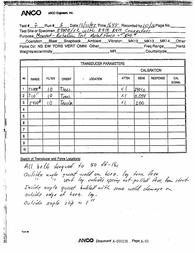
Test#.kRun# -3 Date /Z- 1'3 TImeJ7IY>RecordedbyJCJ/X~g o___ Test Site or Specimen 96WO/z 74 et16 j?qlf9 ~~~
Purpose Mop6q&$ý--/~ ~.~ i~fsc' 'c __OQperation -Blast S__napback Ambient Vibrator:__MK12 MK13 1 MK1 4__Other Force Dir: NS EW TORS VERT OMNI Other Freq Range _Hertz Weights/eccentricity MR counts/cycle
_____ _____ TRANSDUCER1 PARAMETRS
CAUBRATION
NO RANGE FILTER ORIENT LOCATION ATN SENS RESPONSE CAL
SIGNAL.
2 _____f xl~ ___6____o __
3 j'(o 0~ TjiU If___
4 _ _ _ __ _ _ _ _ _ _ _ _ _ _ _ _
5 _ _ _ ______ _ _ _ ______
10
Sketch of Transducer and Force Locations:
A6( ýo (4'7 O W~& ý/• �0 �46�,'4�
(e/ ,ý. , 4~ell11�1' (-Z. 4ýr?
ci �- 4:� �uiie7 6'-�6(�a� CL4K4 f4�c� c-&&4� �t•�-e �
U /7
Fwm #4
ANZODOCUMBnt .A-000236..- Page A.-50,
7 cwlleý'
ac ýf 40 -P /rý
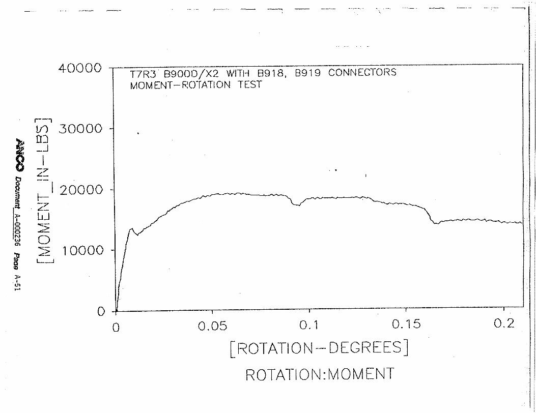
40000 B919 CONNECTORST7R3 B900oI/X2 WITH 8918, MOMENT- ROc)TATION TEST
30000
20000
V)•'
t-
0
L_._.
-I- I 1�� I
I
0 0.05 0.1 0.15 0.2
[ROTATION - DEGREES]
ROTATION:MOMENT
10000
0PI

4
ANCO e*MMs kr
Test#L Runl#.Z.. ate( 2 Time /5vRecorded byviC Page No.___ Test Site orSpecimenl '?C00 YZ- 7 Purpose MwA61- -o ýT-l x-ý ýo7n6 o
Operation Blast --- Snapback Ambient Vibrator: MK12 MK13 M1 Ohe
Force Dir: NS EW TORS VERT OMNI Other Freq Range _Hertz
Weights/eccentricity___ ___- ---- , .MR Counts/cydle
TRANSDUCER PARAMETERS
CAUBRA11ON
NO RANG FILTER ORIENT LOCATION ATTEN SENS RESPONSE CAL SIGNAL
2 ( C) 7(, 0__ ______
3 (C) Th 4 ____
5 _ _ _ _ _ _____
10
Sketch of Transducer and Force Locations:
�V
kCJ'
Cl/ bo aj
CC>"-"t cluý- J1 uerl all, CQ4("t0C/0,>
ke 4.Cj P CjlýW Oef^l- j OL,
6ullwe coawpc/,Cý ( te
Fami "
DocuentA-000236 P~ca A-52
ANPW
I Li
4 '.A t
1..
. . ... ... ./ .
'ee
0000) L'
0 0 oC.)~
_____ -~ - ~ ~ ;ic~.iDi~i~4N1 )~) L(~] ~ L Gl IiUA'\ ~:x,(.)O( ( V* (Bl'~.j ~(~~
':17 ( ) 2
-A
0)
K ~
alwarAwymm
1 N\ I V'-1C V\J r\I C) I I.V _L()
Si-()
rd

Tet ~Run# 6 71/2 M~ Te Recorded b Page No.__
Test S Ite o r S peci men n fe 1A/ O/ / Y e,'4fi' Purpose AM& :074W&ý -! 4yzMA9/ilI__OQperation Blast _Snapback _Ambient. Force Dir: NS EW TORS VERT OMNI Other Weightsifeccentricity
Vibrator: MK1 2 MK13 MKI 4_Other _______________Freq Range Hertz
MR Counts/dcyde
Sketch of Transducer and Force Locations:
Oc,
sYC//.
/ýz.54i5 0ýv -)D 5260 7~
t W- f-
"0q2 C-- 4"'00 7"
Fo~m 84
AN=Docvfer# A-000236 - PagVetA-54
TRANSDUCER PARAMETERS
CAUBRATION
NO RANGE RLTER ORIENT LOCATION ATTEN SENS RESPONSE CAL. _______SIGNAL.
3 #409t/" / ~ _ _ _ __ _ _ x
4 _ _ _ _ _ _ _ _ _ _ _ _ _ _ _ _ _ _ _ _ _ _ _____ _____
5 _ _ _ _ ______________ _____
*10
41
04 40kr, 41ýý ok 9,ot,414 P & ýýelez" 061ýýd' Jý
-/of-k .
,4 V/4,
40000
30000
20000
10000
00 0.05 0.1 0.15
[ROTATION-DEGREES]
ROTATION:MOMENT4
(I
L-J
0
0.2

SNO T ACO Enqhnw2,k
Test #1 Rn# 60 Dae~~ie~ Recordedby (f YPage No.____
Test Site or Specimen rc1Wt_2//r 9/6 Purpose Mai&--,P7.aýIi)[ 24 1a47ICQ%
*Operation Blast Snapoback Ambient Vibrator: MK12 MK13 MK14 Other Force Dir: NS EW TORS VERT OMNI Other Freq RangeHertz Weights/eccentrty MR Counts/tcde,
_____ TRANSOUCEB PARAMETES
CALIBPATION NO RANGE FILTER ORIENT LOCATION ATTEN SENS RESPONSE CAL
SIGNAL
2 03Y'< .Q5
3 _ _ ' _ _4 _ _PA
10
Sketch of Transducer and Force Locations:
1O~)L( C 000'''' )d rA-e t ~
'~Pe"I #J4J Th~A~&co~ 1~a~ ~4 cor
&Q~c~4c~7 4
lo(te'~((; ~ 'oO '«i ~~~eK/1% cot~ec- u/r4C lei4J (7,v- zero
* 6&7L (4ýi/ e~~C~~e~ -ief (( 'oce
~ d/~•~9'ZW '-/6~ ~/~ (o44 t Lle~4r/ ~ C/oz 4 Yt Vf/ (ALotqdycV
M0 W1911(

LCJ
C\i C) (D
Qk

t,,,&a'rrpV,11L I2~' . I.--.--.*.----
40000
1 30000
20000
=
0 :z 10000
0
T7R6 B90OD/X2 WITH 6 MOMENT--ROTATION TEST CORRECTED FOR 9400 I
918) 8919 CONNECTORS
N--LB INITIAL MOMENT
-t I I
0 0.05 0.1
[ROTATION- DEGREES]
ROTATION:MOMENT
0.15 0.2
U.

- - - -. I- -�
40000
30000
20000
10000
00 0.05 0.1 0.15
[ROTATION- DEGREES]
ROTATION:MOMENT
(I)
II
II S0
75.--
0.2

44N D ANCO Erhglnbors, Inc..
rest # Run I ftate~o Time Recorded by4/6J Page No
Test site or Specimen cur 6'Z -OO$l )v . 16 7,-#
Purpose of Test -1vv 6zZ a, r .67
__Operation __Blast __Snapback__Ambienft -Vibrato r:__MiCZ__MK13__?414. Othe IForcc Dir: NS'I:W TORS VERT OMNI Other . req Range Hert Wcights/eccecntricity ,MR_____ Counts/cycle_____
r - - - -TRANSDlUCER PARAMETERS-_ CALIBRATION4
14 AG ITR ORIENT - LOCATION --ENC~ RANGE~ PITRATE ENS RSPONSE SIGNAL
2 ýat O _________ -L 0,031(1 ___
4~ t____ XL 2'& 4 7 0
4 ____ ___________ ____
7 _ _ _ _ _ _ _ _ _
I O _____ ______ _________ _____________________
1 ~ ~ ~ ~ ~ ~ ~ ~ ~ x S ý6 -1- k A J .0- .%%IaS JW&
c)r F( r
qla..o 61v S-IZ
-rof -44ý ANOTFamn D
-t ~~~ ~ -4 .........-N`

T8R1 P1000 WITH MOMENT-ROTATION
P1325 CONNECTOF TEST, CLOSE DIRE(
-700lTION
-650
-600
-550
-500
-450
-4000.1 0.2
[ROTATION - RADIANS]
ROTATION:AXIAL LOAD
'V4/ 0. 21 A'?"'o
I~f)
fn
Li
0 Lbu
F T� t
0

25000
20000
15000
10000
5000
00
[ROTATION- RADIANS]
ROTATIONMOMENT
Ifn
Iz7
w-o Na w1
CA
"C,
0.05 0.1 0.15 0.2

-- - - - ---- ..... . ..... . . ... . .............. ............. -..--.-... .. .. . .......... .. .
44NE::.> ANCO Engln..r, Ic.
rest I Run D.ate-_ Time 1$7Y'( Recorded by JCr. Page No Tes t S it e or Specimen V'4 0 t(
-Mw._
Purpose of Test-Y94~aed- Poiý ýTel e ej 4r ' __Operatlon __Blast __Snapback__Ambient__Vibratos":__AK1Z.__MX13 n14.*Ohe Forcc Dir: NS :tW TORS VERT OMNI Other_ Freq Range Hertz Wcights/eccentricity _, MR Counts/cycle
. TRA2.SDUC-R PARAMETERS _
SCALIBRATION AI
O RANGE FILTER ORIENT LOCATION ATN SENS -S-ONSE - I'Ar
2 dot( 10 A 4l ce
.4
-7
(4__ 1-61.. .. ,
Sketch of Transducer and Force Locations:
form 14
O" 'J",,.9,, A-000236 P•q- A-63
I

25000
20000
15000
10000
5000
0
0 0.05
[ROTATION- RADIANS]
ROTATION:MOMENT
In I-
H-.__
0.1 0.15 0.2
44NE ý0 ANCO EaigineemrInc
rest I' Ru •n f D natei AzTime _(;'_Recorded by j.c.r Page No
Test Site or Specimen POGO e~A 1 1 5y; Purpose of Testff0"z't/$- leO a)4644 AThI c,77i4 !-JcY: -c- t __Operat ion __last _Snapback__Ambient __Vibrator/:__kX12__,1C13_ _1X14. Other Force I)ir: NS'I !W TORS VERT OMNI Other_ Freq Range Hertz Weights/ccccntricity , HR Counts/cycle
TRANSDUCER PARAMETERS
CALIBRATION O RANGE FILTER ORIENT LOCATION ATTEN SENS ,qSPONS IG -S_-S I GNAL t .... , ".10 "-•e: { gcoto
ý •(G (0. • :,•: - D :,o.• , '"
'I______ _________ _____________
S
7
StI o Transducer and Force Locations:
Sketch of Transducer and Force Locations:
form A4
6
~o~izA-000236 At
I
25000
20000
15000
10000
5000
00 0.05 0.1 0.15
[FROTATION -- RADIANS]
ROTATION: MOM[ MNT
m (/)
nmu '•, t-
;j H-
0.2

44141:0 ANCO Enginwefs Inc.
rest ff Ru~n #J Date 14, - TimeZ.ýZL. Recorded by ,A4f Page No
Test Site or Specimen tO ( (Aw ?761 /0 Purpose of Test Mea/ X&4/ 116 #* I~ . __;7;Te~ ~
-Operation __Blast -_snap back__Amb i ent __Vibrator: MK12__MX13 MX14- Other Forcc IDir: NS'I..W TORS VERT OMNI Other__________ Freq Range Hertz Wcights/ccccntricity , MR Counts/cycle
TRANSDUCER PARAMETERS_
CALIBRATIO'N
O 0RANGE FILTER ORIENT LOCATION ATTE"N SEN SPON- -qSIGNA
1 it-coo0 to 7rca ae -6e ________
,3 24(0,00 _______ gxL* Zoo ______
4 _ _ _ _ ___________ _ _ _ _ __ _ _ _ _
Sketch of Transducer and Force Locations:
form II4
r
n_=jr--"f A-67 -A-AO0236-

4N~~ ANCO Engine~en, Inc.
rest f to Run *af fate I( ~i•Time 180r) Recorded Test Site or Specimen P-J(1(w 2 Purpose of Test 044 - r{ _Operation _Blast __Snapback__Ambient __Vibrator:_ MKI Forcc lDir: NS I:M TORS VERT ONI Other_ p Wcights/cccntri city_.......... , MR C
by.C,,C. Page No
SA
Z.__MK13 __MX14 Other :req Range Hertz :ounts/cycle
TRANSDUCER PARAMETERS
CALIBRATION 01RANGE FILTER ORIENT LOCATION ATTEN SENS RESPONS - A I
,__ _-_ _ _ _ _ SIGNAL ]
21 -t'( t6 7rg' c /,wa-k ,,_ _ to. .... 01y_
3 ,,"# -Z C" (o A, ",ý ", •Z o. 4 S __ _ _ _ _ _ __ _ _ _ _ _ __ _ _ _ _ _ ___ _ _ _ _ _
6S 7
Sketch of Transducer and Force Locations:
Saxe W,,e
form #4
11
-:'•''"', •c,•,•o'z A-000236 !P",•o A-68

80000
60000
40000
20000
00 0.05 0.1
[ROTATION - DEGRFES] ROTATION :MOM ENI-
c8
CD
C>
i--
I-. z
0
0.15 0.2
4N~~ ANCO Engineers, Inc.
rest f 1Q. Run f DatefYr Time /&Or Recorded by -JC Page No
Test Site or Specimen P•0, w,•< L 2(!C(V) -O Z
Purpose of Test lgvA 4ý 4/Q4Le.S,- &~~% sc-00 Operation Blast Snapback Ambient Vibrator: MK1Z MXl3 MX14. Other
Forec I)ir: NS'iW TORS VERT OMNI Other Freq Range Hertz
Wcights/ccccntricity ,MR Counts/cycle
TRANSDUCER PARAMETERS NO RAE FCALIBRATION
0RANGE FLTER ORIENT LOCATION ATTEN SSENS SPONSE -SIN
1 SIGNAL
3 ,( (0 A,<_c', -zoo, 4
6 7
Sketch of Transducer and Force Locations:
o 4(W -7:( f,24o 9- v4c- /,,
form 14
' c,. r_.en• A-000236 PF?'O A-70

80000
60000
40000
20000
0
0.05 0.1
[ROTATION -DEGREES] ROTATION :MOM ENT
m F-J
z
0i
0
0 0.15 0.21

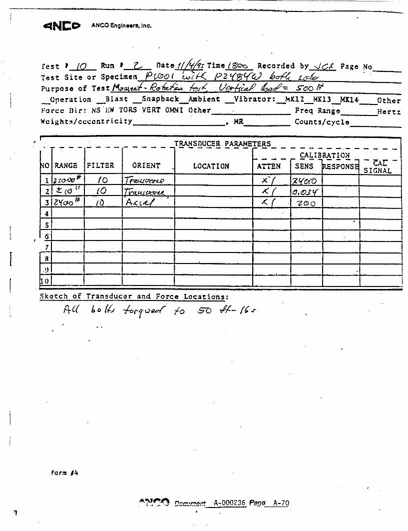
ANC CIPANCO Engineer3, Inc.
rest i iQ_ Run # ý nate Time /7- Recorded by. JCf Page No Test Site or Specimen j/Q(fO{ / 2 "'
Purpose of Test -Kstwl Awzýr _(A~f1f 6Mxr- o __.Operation _Blast S__napback__Ambient -Vibrator: _klZ__MX13__MX•_4. Other Forcc l)ir: NS 1:W TORS VERT OMNI Other Freq Range Hertz
Wcight./ccccntricity_, MR- 'Counts/cycle
TRANSDUCER PARAMETERS_
CALIBRATION
0 RANGE FILTER ORIENT LOCATION ATTEN SENS SPONS S I GA ,,__ _ _,__ __ __ S IGNAL
3 i'JY 0 _ _ __ _ __ _
4
6
7
L o
Sketch of Transducer and Force Locat~ions:
4 _~ ~_j__ _ _ _______ __*____D_____
form 14
crP!A-0100236 A-72

- -- -. 4 --
80000
60000
40000
20000
00 0.05 0.1 0.15
[ROTATION - DEGREE S] ROTATION:MOMENT
ri, (I)
CD 0 2I
Cz
,-L4
C.)
*0.2

ATTACHMENT I
f-1