Embed Size (px)
Citation preview
User's Guide
Revision 1.0b
AOC-S3908L-H8iRAOC-S3908L-H8iR-32DDAOC-S3908L-H8iR-16DD
AOC-S3916L-H16iRAOC-S3916L-H16iR-32DD
The information in this User's Guide has been carefully reviewed and is believed to be accurate. The vendor assumes no responsibility for any inaccuracies that may be contained in this document, and makes no commitment to update or to keep current the information in this user's guide, or to notify any person or organization of the updates. Please Note: For the most up-to-date version of this user's guide, please see our Website at www.supermicro.com.Super Micro Computer, Inc. ("Supermicro") reserves the right to make changes to the product described in this user's guide at any time and without notice. This product, including software and documentation, is the property of Supermicro and/or its licensors, and is supplied only under a license. Any use or reproduction of this product is not allowed, except as expressly permitted by the terms of said license.IN NO EVENT WILL SUPER MICRO COMPUTER, INC. BE LIABLE FOR DIRECT, INDIRECT, SPECIAL, INCIDENTAL, SPECULATIVE OR CONSEQUENTIAL DAMAGES ARISING FROM THE USE OR INABILITY TO USE THIS PRODUCT OR DOCUMENTATION, EVEN IF ADVISED OF THE POSSIBILITY OF SUCH DAMAGES. IN PARTICULAR, SUPER MICRO COMPUTER, INC. SHALL NOT HAVE LIABILITY FOR ANY HARDWARE, SOFTWARE, OR DATA STORED OR USED WITH THE PRODUCT, INCLUDING THE COSTS OF REPAIRING, REPLACING, INTEGRATING, INSTALLING OR RECOVERING SUCH HARDWARE, SOFTWARE, OR DATA.
Any disputes arising between the manufacturer and the customer shall be governed by the laws of Santa Clara County in the State of California, USA. The State of California, County of Santa Clara shall be the exclusive venue for the resolution of any such disputes. Supermicro's total liability for all claims will not exceed the price paid for the hardware product.
FCC Statement: This equipment has been tested and found to comply with the limits for a Class A or Class B digital device pursuant to Part 15 of the FCC Rules. These limits are designed to provide reasonable protection against harmful interference when the equipment is operated in industrial environment for Class A device or in residential environment for Class B device. This equipment generates, uses, and can radiate radio frequency energy and, if not installed and used in accordance with the manufacturer’s instruction manual, may cause harmful interference with radio communications. Operation of this equipment in a residential area is likely to cause harmful interference, in which case you will be required to correct the interference at your own expense.
California Best Management Practices Regulations for Perchlorate Materials: This Perchlorate warning applies only to products containing CR (Manganese Dioxide) Lithium coin cells. “Perchlorate Material-special handling may apply. See www.dtsc.ca.gov/hazardouswaste/perchlorate”.
WARNING: This product can expose you to chemicals including lead, known to the State of California to cause cancer and birth defects or other reproductive harm. For more information, go to www.P65Warnings.ca.gov.
!
The products sold by Supermicro are not intended for and will not be used in life support systems, medical equipment, nuclear facilities or systems, aircraft, aircraft devices, aircraft/emergency communication devices or other critical systems whose failure to perform be reasonably expected to result in significant injury or loss of life or catastrophic property damage. Accordingly, Supermicro disclaims any and all liability, and should buyer use or sell such products for use in such ultra-hazardous applications, it does so entirely at its own risk. Furthermore, buyer agrees to fully indemnify, defend and hold Supermicro harmless for and against any and all claims, demands, actions, litigation, and proceedings of any kind arising out of or related to such ultra-hazardous use or sale.
User's Guide Revision 1.0bRelease Date: November 4, 2021Unless you request and receive written permission from Super Micro Computer, Inc., you may not copy any part of this document.Information in this document is subject to change without notice. Other products and companies referred to herein are trademarks or registered trademarks of their respective companies or mark holders.Copyright © 2021 by Super Micro Computer, Inc. All rights reserved. Printed in the United States of America
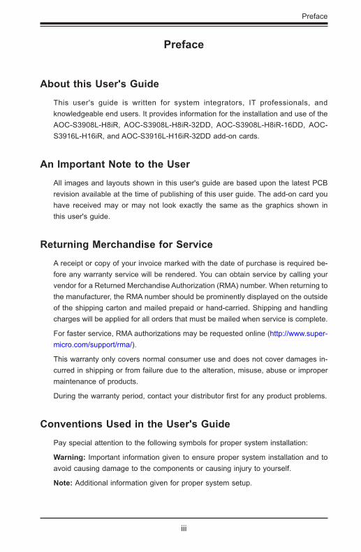
Preface
About this User's GuideThis user's guide is written for system integrators, IT professionals, and knowledgeable end users. It provides information for the installation and use of the AOC-S3908L-H8iR, AOC-S3908L-H8iR-32DD, AOC-S3908L-H8iR-16DD, AOC-S3916L-H16iR, and AOC-S3916L-H16iR-32DD add-on cards.
An Important Note to the UserAll images and layouts shown in this user's guide are based upon the latest PCB revision available at the time of publishing of this user guide. The add-on card you have received may or may not look exactly the same as the graphics shown in this user's guide.
Returning Merchandise for ServiceA receipt or copy of your invoice marked with the date of purchase is required be-fore any warranty service will be rendered. You can obtain service by calling your vendor for a Returned Merchandise Authorization (RMA) number. When returning to the manufacturer, the RMA number should be prominently displayed on the outside of the shipping carton and mailed prepaid or hand-carried. Shipping and handling charges will be applied for all orders that must be mailed when service is complete.
For faster service, RMA authorizations may be requested online (http://www.super-micro.com/support/rma/).
This warranty only covers normal consumer use and does not cover damages in-curred in shipping or from failure due to the alteration, misuse, abuse or improper maintenance of products.
During the warranty period, contact your distributor first for any product problems.
Conventions Used in the User's GuidePay special attention to the following symbols for proper system installation:
Warning: Important information given to ensure proper system installation and to avoid causing damage to the components or causing injury to yourself.
Note: Additional information given for proper system setup.
Preface
iii
iv
AOC-S3908L-H8iR(-32DD/16DD)/AOC-S3916L-H16iR(-32DD) User's Guide
Important LinksFor your system to work properly, please follow the links below to download all necessary drivers/utilities and the user’s manual for your server.
• Supermicro product manuals: http://www.supermicro.com/support/manuals/
• Product drivers and utilities: https://www.supermicro.com/wdl/driver
• Product safety info: http://www.supermicro.com/about/policies/safety_informa-tion.cfm
• If you have any questions, please contact our support team at: [email protected]
This manual may be periodically updated without notice. Please check the Supermicro website for possible updates to the manual revision level.

v
Preface
Contacting Supermicro
HeadquartersAddress: Super Micro Computer, Inc.
980 Rock Ave.
San Jose, CA 95131 U.S.A.
Tel: +1 (408) 503-8000
Fax: +1 (408) 503-8008
Email: [email protected] (General Information)
[email protected] (Technical Support)
Web Site: www.supermicro.com
EuropeAddress: Super Micro Computer B.V.
Het Sterrenbeeld 28, 5215 ML
's-Hertogenbosch, The Netherlands
Tel: +31 (0) 73-6400390
Fax: +31 (0) 73-6416525
Email: [email protected] (General Information)
[email protected] (Technical Support)
[email protected] (Customer Support)
Web Site: www.supermicro.nl
Asia-PacificAddress: Super Micro Computer, Inc.
3F, No. 150, Jian 1st Rd.
Zhonghe Dist., New Taipei City 235
Taiwan (R.O.C)
Tel: +886-(2) 8226-3990
Fax: +886-(2) 8226-3992
Email: [email protected]
Web Site: www.supermicro.com.tw
Table of Contents
PrefaceAbout this User's Guide ................................................................................................ 3An Important Note to the User ...................................................................................... 3Returning Merchandise for Service ............................................................................... 3Conventions Used in the User's Guide ......................................................................... 3Important Links .............................................................................................................. 4Contacting Supermicro .................................................................................................. 5
Chapter 1 Introduction1-1 Overview ......................................................................................................... 1-11-2 About this Add-on Card ................................................................................... 1-11-3 Key Features ................................................................................................... 1-1
Chapter 2 Hardware Components2-1 Add-On Card Image and Layout ..................................................................... 2-12-2 Major Onboard Components ........................................................................... 2-22-3 SAS 3.0 Ports and Headers............................................................................ 2-3
SAS Ports ................................................................................................... 2-3Serial Debug UART Header ....................................................................... 2-5UART0 Header ........................................................................................... 2-5SBL_Disable Jumper .................................................................................. 2-5SuperCap 9-pin Connector ........................................................................ 2-5
2-4 Front LED Indicators ....................................................................................... 2-6PSoC Heartbeat LED ................................................................................. 2-6ONFI Activity LED ...................................................................................... 2-6
2-5 Rear LED Indicators ........................................................................................ 2-7System Error LED ...................................................................................... 2-7Overtemp LED ............................................................................................ 2-7EPAK_FLT LED .......................................................................................... 2-7System Heartbeat LED .............................................................................. 2-8
Chapter 3 Installation3-1 Static-Sensitive Devices .................................................................................. 3-1
Precautions ..................................................................................................... 3-13-2 Before Installation ........................................................................................... 3-23-3 Installing the Add-on Card .............................................................................. 3-2
AOC-S3908L-H8iR(-32DD/16DD)/AOC-S3916L-H16iR(-32DD) User's Guide
vi
Table of Contents
Chapter 4 Configuring the Broadcom MegaRAID Setting4-1 RAID Minimum Drive Requirements ............................................................... 4-14-2 Using the Broadcom MegaRAID Configuration Utility .................................... 4-24-3 The Broadcom MegaRAID Main Screen ........................................................ 4-44-4 Creating a Virtual Drive ................................................................................... 4-64-5 Drive Management ........................................................................................ 4-124-6 Controller Management ................................................................................. 4-144-7 Properties ...................................................................................................... 4-174-8 Foreign Configuration Management .............................................................. 4-19
Chapter 5 MegaRAID Controller Firmware Update Procedures5-1 Flashing Firmware Using StorCLI under DOS ................................................ 5-15-2 Flashing Firmware Using MegaRAID Storage Manager ................................ 5-3
Chapter 6 Booting6-1 Configuring Boot Settings ............................................................................... 4-1
vi

vi
AOC-S3908L-H8iR(-32DD/16DD)/AOC-S3916L-H16iR(-32DD) User's Guide
Notes
Chapter 1: Overview
1-1
Chapter 1
Introduction
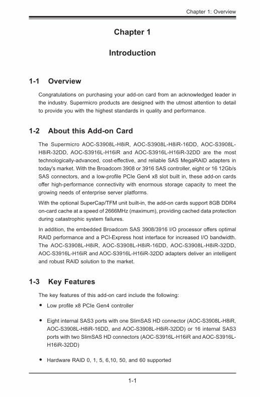
1-1 OverviewCongratulations on purchasing your add-on card from an acknowledged leader in the industry. Supermicro products are designed with the utmost attention to detail to provide you with the highest standards in quality and performance.
1-2 About this Add-on CardThe Supermicro AOC-S3908L-H8iR, AOC-S3908L-H8iR-16DD, AOC-S3908L-H8iR-32DD, AOC-S3916L-H16iR and AOC-S3916L-H16iR-32DD are the most technologically-advanced, cost-effective, and reliable SAS MegaRAID adapters in today's market. With the Broadcom 3908 or 3916 SAS controller, eight or 16 12Gb/s SAS connectors, and a low-profile PCIe Gen4 x8 slot built in, these add-on cards offer high-performance connectivity with enormous storage capacity to meet the growing needs of enterprise server platforms.
With the optional SuperCap/TFM unit built-in, the add-on cards support 8GB DDR4 on-card cache at a speed of 2666MHz (maximum), providing cached data protection during catastrophic system failures.
In addition, the embedded Broadcom SAS 3908/3916 I/O processor offers optimal RAID performance and a PCI-Express host interface for increased I/O bandwidth. The AOC-S3908L-H8iR, AOC-S3908L-H8iR-16DD, AOC-S3908L-H8iR-32DD, AOC-S3916L-H16iR and AOC-S3916L-H16iR-32DD adapters deliver an intelligent and robust RAID solution to the market.
1-3 Key FeaturesThe key features of this add-on card include the following:
• Low profile x8 PCIe Gen4 controller
• Eight internal SAS3 ports with one SlimSAS HD connector (AOC-S3908L-H8iR, AOC-S3908L-H8iR-16DD, and AOC-S3908L-H8iR-32DD) or 16 internal SAS3 ports with two SlimSAS HD connectors (AOC-S3916L-H16iR and AOC-S3916L-H16iR-32DD)
• Hardware RAID 0, 1, 5, 6,10, 50, and 60 supported
1-2
AOC-S3908L-H8iR(-32DD/16DD)/AOC-S3916L-H16iR(-32DD) User's Guide
• Supports up to 16 (AOC-S3908L-H8iR-16DD), 32 (AOC-S3908L-H8iR-32DD and AOC-S3916L-H16iR-32DD), or 240 (AOC-S3908L-H8iR and AOC-S3916L-H16iR) physical devices with expander
• 8GB DDR4 on-card cache with a speed of up to 2666MHz for cached data protection
• 1x (AOC-S3908L-H8iR, AOC-S3908L-H8iR-16DD, and AOC-S3908L-H8iR-32DD) or 2x (AOC-S3916L-H16iR and AOC-S3916L-H16iR-32DD) SlimSAS x8 black (100 Ohm) connector(s)
• Supports MCTP over PCIe
• On-board TFM Included
• CacheVault to protect onboard cache memory
• Optional SuperCap BTR-CVPM05
• Supports LSA Storage Authority Software WebGUI
• Secure Boot
• Support includes advanced software encryption
• Supports 3.0, 6.0, and 12.0 Gb/s SAS, and 3.0 & 6.0 Gb SATA data transfer rates
• OS support: Windows and Linux
• UEFI Configuration Utility only
• UEFI/Legacy Boot
• Power consumption: 14 (AOC-S3908L-H8iR, AOC-S3908L-H8iR-16DD, and AOC-S3908L-H8iR-32DD) or 18 (AOC-S3916L-H16iR and AOC-S3916L-H16iR-32DD) watts
• Thermal operating range: system-dependent (55°C or higher with sufficient airflow)
• Dimensions 2.71" (H) x 6.6" (L) (68.83cm (H) x 167.64cm (L))
Chapter 2: Hardware Components
2-1
Chapter 2
Hardware Components
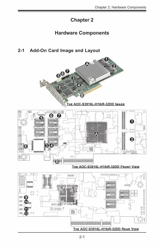
2-1 Add-On Card Image and Layout
2A1
B
8 43
6
The AOC-S3916L-H16iR-32DD Front View
2A
1
B
8 43
6 7
7
The AOC-S3916L-H16iR-32DD Image
5
5
910
1112
The AOC-S3916L-H16iR-32DD Rear View
2-2
AOC-S3908L-H8iR(-32DD/16DD)/AOC-S3916L-H16iR(-32DD) User's Guide
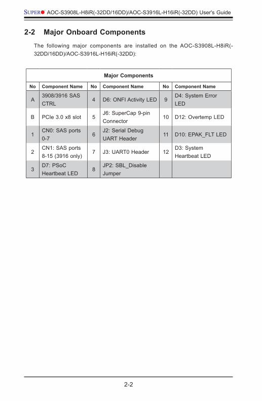
Major Components
No Component Name No Component Name No Component Name
A3908/3916 SAS CTRL
4 D6: ONFI Activity LED 9D4: System Error LED
B PCIe 3.0 x8 slot 5J6: SuperCap 9-pin Connector
10 D12: Overtemp LED
1CN0: SAS ports 0-7
6J2: Serial Debug UART Header
11 D10: EPAK_FLT LED
2CN1: SAS ports 8-15 (3916 only)
7 J3: UART0 Header 12D3: System Heartbeat LED
3D7: PSoC Heartbeat LED
8JP2: SBL_Disable Jumper
2-2 Major Onboard ComponentsThe following major components are installed on the AOC-S3908L-H8iR(-32DD/16DD)/AOC-S3916L-H16iR(-32DD):
Chapter 2: Hardware Components
2-3
2-3 SAS 3.0 Ports and Headers
SAS Ports
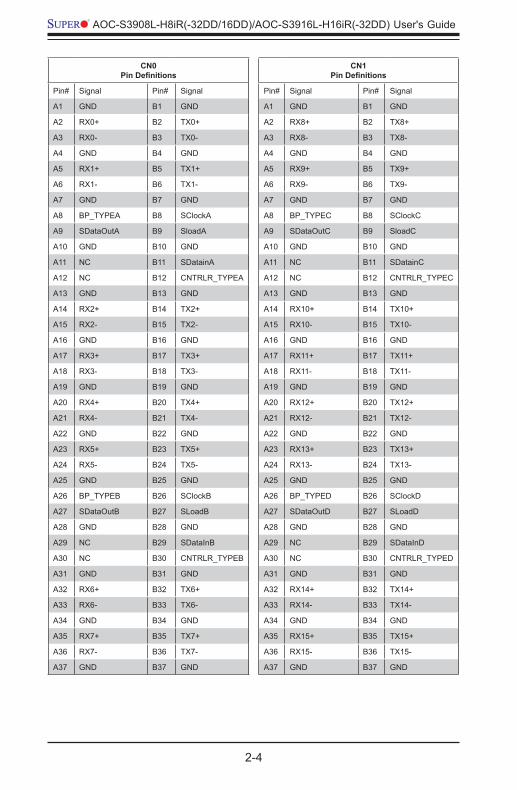
Eight SAS ports, supported by the CN0 connector on the Broadcom 3908 SAS controller, or 16 SAS ports, supported by the CN0 and CN1 connectors on the Broadcom 3916 SAS controller, are located on the add-on card. SAS 0-7 and SAS 8-15 support SAS3 SFF-8654 connections. See the tables on the following page for pin definitions.
2-4
AOC-S3908L-H8iR(-32DD/16DD)/AOC-S3916L-H16iR(-32DD) User's Guide
CN0Pin Definitions
Pin# Signal Pin# Signal
A1 GND B1 GND
A2 RX0+ B2 TX0+
A3 RX0- B3 TX0-
A4 GND B4 GND
A5 RX1+ B5 TX1+
A6 RX1- B6 TX1-
A7 GND B7 GND
A8 BP_TYPEA B8 SClockA
A9 SDataOutA B9 SloadA
A10 GND B10 GND
A11 NC B11 SDatainA
A12 NC B12 CNTRLR_TYPEA
A13 GND B13 GND
A14 RX2+ B14 TX2+
A15 RX2- B15 TX2-
A16 GND B16 GND
A17 RX3+ B17 TX3+
A18 RX3- B18 TX3-
A19 GND B19 GND
A20 RX4+ B20 TX4+
A21 RX4- B21 TX4-
A22 GND B22 GND
A23 RX5+ B23 TX5+
A24 RX5- B24 TX5-
A25 GND B25 GND
A26 BP_TYPEB B26 SClockB
A27 SDataOutB B27 SLoadB
A28 GND B28 GND
A29 NC B29 SDataInB
A30 NC B30 CNTRLR_TYPEB
A31 GND B31 GND
A32 RX6+ B32 TX6+
A33 RX6- B33 TX6-
A34 GND B34 GND
A35 RX7+ B35 TX7+
A36 RX7- B36 TX7-
A37 GND B37 GND
CN1Pin Definitions
Pin# Signal Pin# Signal
A1 GND B1 GND
A2 RX8+ B2 TX8+
A3 RX8- B3 TX8-
A4 GND B4 GND
A5 RX9+ B5 TX9+
A6 RX9- B6 TX9-
A7 GND B7 GND
A8 BP_TYPEC B8 SClockC
A9 SDataOutC B9 SloadC
A10 GND B10 GND
A11 NC B11 SDatainC
A12 NC B12 CNTRLR_TYPEC
A13 GND B13 GND
A14 RX10+ B14 TX10+
A15 RX10- B15 TX10-
A16 GND B16 GND
A17 RX11+ B17 TX11+
A18 RX11- B18 TX11-
A19 GND B19 GND
A20 RX12+ B20 TX12+
A21 RX12- B21 TX12-
A22 GND B22 GND
A23 RX13+ B23 TX13+
A24 RX13- B24 TX13-
A25 GND B25 GND
A26 BP_TYPED B26 SClockD
A27 SDataOutD B27 SLoadD
A28 GND B28 GND
A29 NC B29 SDataInD
A30 NC B30 CNTRLR_TYPED
A31 GND B31 GND
A32 RX14+ B32 TX14+
A33 RX14- B33 TX14-
A34 GND B34 GND
A35 RX15+ B35 TX15+
A36 RX15- B36 TX15-
A37 GND B37 GND
Chapter 2: Hardware Components
2-5
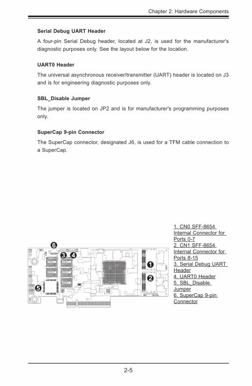
Serial Debug UART Header
A four-pin Serial Debug header, located at J2, is used for the manufacturer's diagnostic purposes only. See the layout below for the location.
UART0 Header
The universal asynchronous receiver/transmitter (UART) header is located on J3 and is for engineering diagnostic purposes only.
SBL_Disable Jumper
The jumper is located on JP2 and is for manufacturer's programming purposes only.
SuperCap 9-pin Connector
The SuperCap connector, designated J6, is used for a TFM cable connection to a SuperCap.
1. CN0 SFF-8654 Internal Connector for Ports 0-72. CN1 SFF-8654 Internal Connector for Ports 8-153. Serial Debug UART Header4. UART0 Header5. SBL_Disable Jumper6. SuperCap 9-pin Connector
2
13 4
5
6
2-6
AOC-S3908L-H8iR(-32DD/16DD)/AOC-S3916L-H16iR(-32DD) User's Guide
2-4 Front LED Indicators
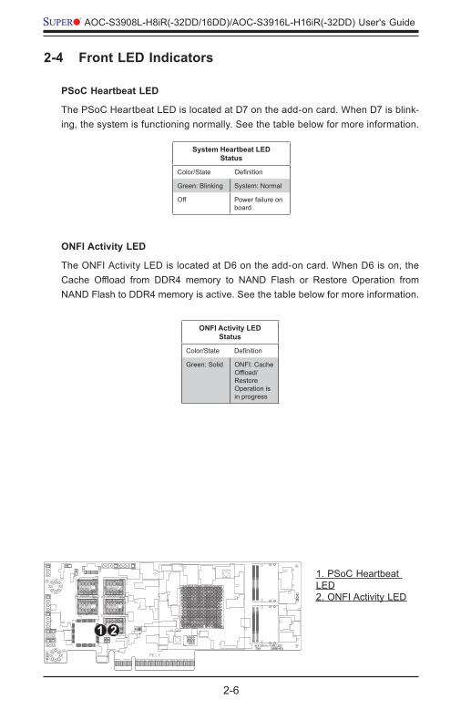
PSoC Heartbeat LED
The PSoC Heartbeat LED is located at D7 on the add-on card. When D7 is blink-ing, the system is functioning normally. See the table below for more information.
System Heartbeat LEDStatus
Color/State Definition
Green: Blinking System: Normal
Off Power failure on board
ONFI Activity LED
The ONFI Activity LED is located at D6 on the add-on card. When D6 is on, the Cache Offload from DDR4 memory to NAND Flash or Restore Operation from NAND Flash to DDR4 memory is active. See the table below for more information.
ONFI Activity LEDStatus
Color/State Definition
Green: Solid ONFI: Cache Offload/Restore Operation is in progress
1. PSoC Heartbeat LED2. ONFI Activity LED
21
Chapter 2: Hardware Components
2-7
2-5 Rear LED Indicators
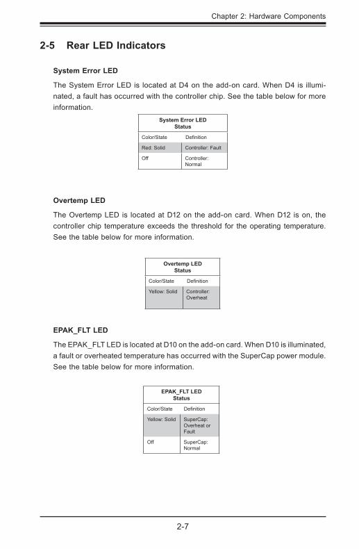
System Error LED
The System Error LED is located at D4 on the add-on card. When D4 is illumi-nated, a fault has occurred with the controller chip. See the table below for more information.
System Error LEDStatus
Color/State Definition
Red: Solid Controller: Fault
Off Controller: Normal
Overtemp LED
The Overtemp LED is located at D12 on the add-on card. When D12 is on, the controller chip temperature exceeds the threshold for the operating temperature. See the table below for more information.
Overtemp LEDStatus
Color/State Definition
Yellow: Solid Controller: Overheat
EPAK_FLT LED
The EPAK_FLT LED is located at D10 on the add-on card. When D10 is illuminated, a fault or overheated temperature has occurred with the SuperCap power module. See the table below for more information.
EPAK_FLT LEDStatus
Color/State Definition
Yellow: Solid SuperCap: Overheat or Fault
Off SuperCap: Normal
2-8
AOC-S3908L-H8iR(-32DD/16DD)/AOC-S3916L-H16iR(-32DD) User's Guide
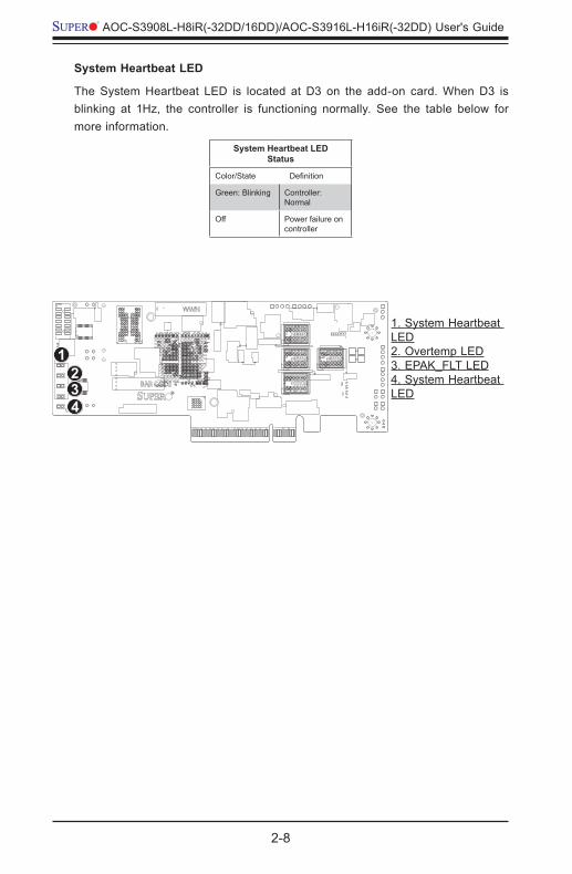
1. System Heartbeat LED2. Overtemp LED3. EPAK_FLT LED4. System Heartbeat LED
21
43
System Heartbeat LED
The System Heartbeat LED is located at D3 on the add-on card. When D3 is blinking at 1Hz, the controller is functioning normally. See the table below for more information.
System Heartbeat LEDStatus
Color/State Definition
Green: Blinking Controller: Normal
Off Power failure on controller
3-1
Chapter 3: Installation
Chapter 3
Installation
Note: Your system came with the adapter pre-installed as a part of an integrated solution. We do not recommend that any part of your system components be re-moved and re-installed. However, if you do need to remove or re-install a system component, including this add-on card, please follow the instructions below to ensure proper system setup. Also, be sure to remove the power cord first before adding, removing or changing any hardware components to avoid damaging the system or components.
3-1 Static-Sensitive DevicesElectrostatic Discharge (ESD) can damage electronic com ponents. To avoid dam-aging your add-on card, it is important to handle it very carefully. The following measures are generally sufficient to protect your equipment from ESD.
Precautions• Use a grounded wrist strap designed to prevent static discharge.
• Touch a grounded metal object before removing the add-on card from the antistatic bag.
• Handle the add-on card by its edges only; do not touch its components, or peripheral chips.
• Put the add-on card back into the antistatic bags when not in use.
• For grounding purposes, make sure that your system chassis provides excel-lent conductivity between the power supply, the case, the mounting fasteners, and the add-on card.
3-2
AOC-S3908L-H8iR(-32DD/16DD)/AOC-S3916L-H16iR(-32DD) User's Guide
3-2 Before InstallationTo install the add-on card properly, be sure to follow the instructions below.
1. Power down the system.
2. Remove the power cord from the wall socket.
3. Use industry-standard anti-static equipment (such as gloves or wrist strap) and follow the instructions listed on Page 3-1 to avoid damage caused by ESD.
4. Familiarize yourself with the server, motherboard, and/or chassis documenta-tion.
5. Make sure that your operating system includes the latest updates and hot-fixes.
3-3 Installing the Add-on CardFollow the steps below to install the add-on card into your system.
1. Remove the server cover and, if necessary, set aside any screws for later use.
2. Remove the add-on card slot cover. If the case requires a screw, place the screw aside for later use.
3. Position the add-on card in the slot directly over the connector, and gently push down on both sides of the card until it slides into the PCI connector.
4. Secure the add-on card to the chassis. If required, use the screw that you previously removed.
5. Attach any necessary external cables to the add-on card.
6. Replace the chassis cover.
7. Plug the power cord into the wall socket, and power up the system.
4-1
Chapter 4: Configuring the Broadcom MegaRAID Setting
Chapter 4
Configuring the Broadcom MegaRAID Setting
This chapter provides instructions on how to configure MegaRAID settings for the Broadcom 3908 and 3916 SAS controllers. If you do not wish to configure Mega-RAID settings, skip this section and go directly to OS installation.
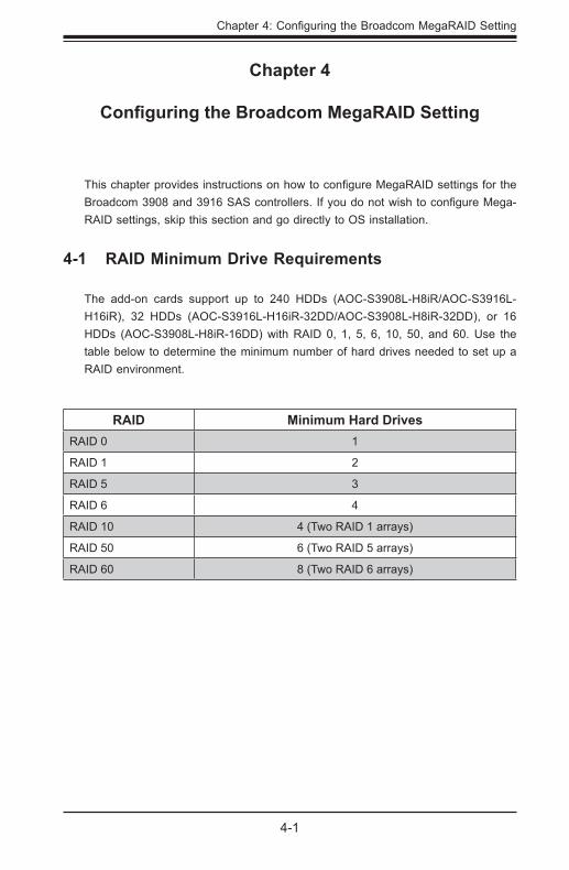
4-1 RAID Minimum Drive Requirements
The add-on cards support up to 240 HDDs (AOC-S3908L-H8iR/AOC-S3916L-H16iR), 32 HDDs (AOC-S3916L-H16iR-32DD/AOC-S3908L-H8iR-32DD), or 16 HDDs (AOC-S3908L-H8iR-16DD) with RAID 0, 1, 5, 6, 10, 50, and 60. Use the table below to determine the minimum number of hard drives needed to set up a RAID environment.
RAID Minimum Hard DrivesRAID 0 1
RAID 1 2
RAID 5 3
RAID 6 4
RAID 10 4 (Two RAID 1 arrays)
RAID 50 6 (Two RAID 5 arrays)
RAID 60 8 (Two RAID 6 arrays)
4-2
AOC-S3908L-H8iR(-32DD/16DD)/AOC-S3916L-H16iR(-32DD) User's Guide
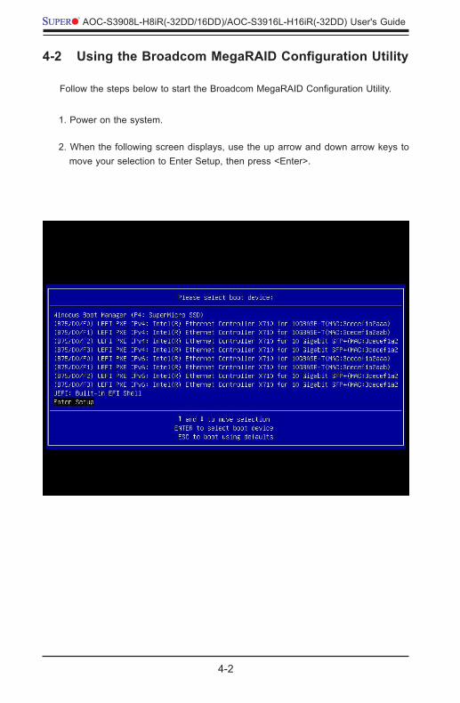
4-2 Using the Broadcom MegaRAID Configuration Utility
Follow the steps below to start the Broadcom MegaRAID Configuration Utility.
1. Power on the system.
2. When the following screen displays, use the up arrow and down arrow keys to move your selection to Enter Setup, then press <Enter>.
4-3
Chapter 4: Configuring the Broadcom MegaRAID Setting
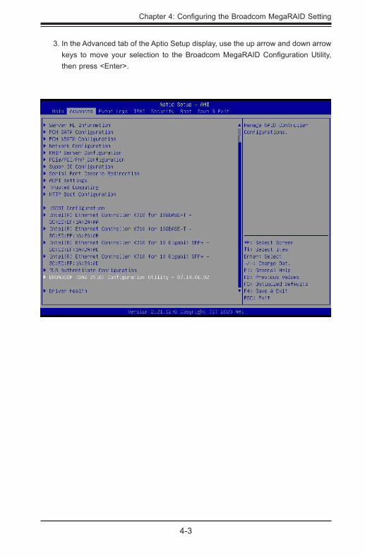
3. In the Advanced tab of the Aptio Setup display, use the up arrow and down arrow keys to move your selection to the Broadcom MegaRAID Configuration Utility, then press <Enter>.
4-4
AOC-S3908L-H8iR(-32DD/16DD)/AOC-S3916L-H16iR(-32DD) User's Guide
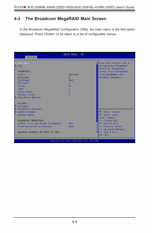
4-3 The Broadcom MegaRAID Main Screen
In the Broadcom MegaRAID Configuration Utility, the main menu is the first option displayed. Press <Enter> to be taken to a list of configurable menus.
4-5
Chapter 4: Configuring the Broadcom MegaRAID Setting
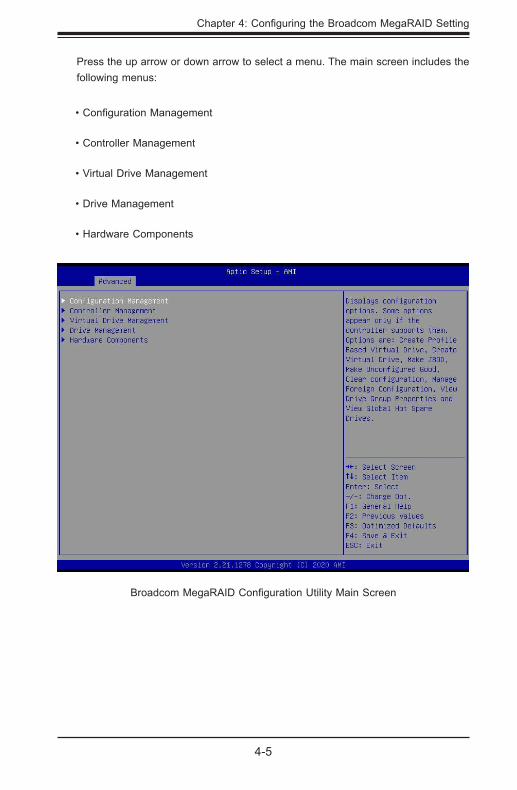
Press the up arrow or down arrow to select a menu. The main screen includes the following menus:
• Configuration Management
• Controller Management
• Virtual Drive Management
• Drive Management
• Hardware Components
Broadcom MegaRAID Configuration Utility Main Screen
4-6
AOC-S3908L-H8iR(-32DD/16DD)/AOC-S3916L-H16iR(-32DD) User's Guide
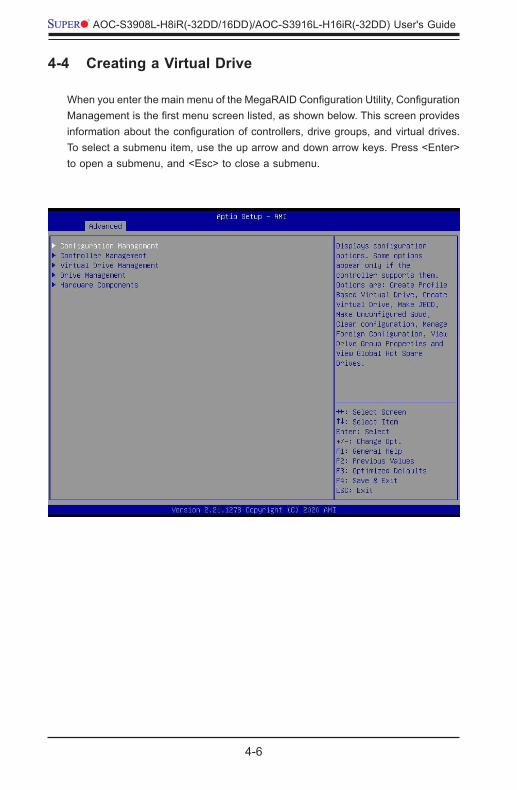
4-4 Creating a Virtual Drive
When you enter the main menu of the MegaRAID Configuration Utility, Configuration Management is the first menu screen listed, as shown below. This screen provides information about the configuration of controllers, drive groups, and virtual drives. To select a submenu item, use the up arrow and down arrow keys. Press <Enter> to open a submenu, and <Esc> to close a submenu.
4-7
Chapter 4: Configuring the Broadcom MegaRAID Setting
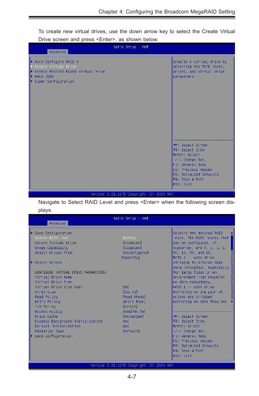
To create new virtual drives, use the down arrow key to select the Create Virtual Drive screen and press <Enter>, as shown below.
Navigate to Select RAID Level and press <Enter> when the following screen dis-plays.
4-8
AOC-S3908L-H8iR(-32DD/16DD)/AOC-S3916L-H16iR(-32DD) User's Guide
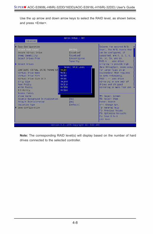
Use the up arrow and down arrow keys to select the RAID level, as shown below, and press <Enter>.
Note: The corresponding RAID level(s) will display based on the number of hard drives connected to the selected controller.
4-9
Chapter 4: Configuring the Broadcom MegaRAID Setting
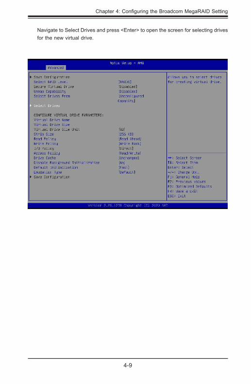
Navigate to Select Drives and press <Enter> to open the screen for selecting drives for the new virtual drive.
4-10
AOC-S3908L-H8iR(-32DD/16DD)/AOC-S3916L-H16iR(-32DD) User's Guide
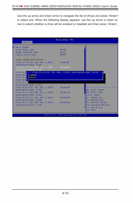
Use the up arrow and down arrow to navigate the list of drives and press <Enter> to select one. When the following display appears, use the up arrow or down ar-row to select whether a drive will be enabled or disabled and then press <Enter>.
4-11
Chapter 4: Configuring the Broadcom MegaRAID Setting
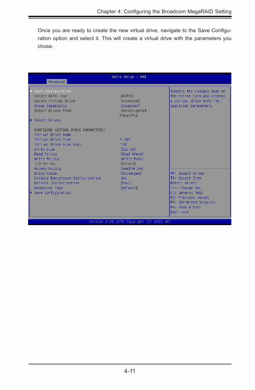
Once you are ready to create the new virtual drive, navigate to the Save Configu-ration option and select it. This will create a virtual drive with the parameters you chose.
4-12
AOC-S3908L-H8iR(-32DD/16DD)/AOC-S3916L-H16iR(-32DD) User's Guide
4-5 Drive Management
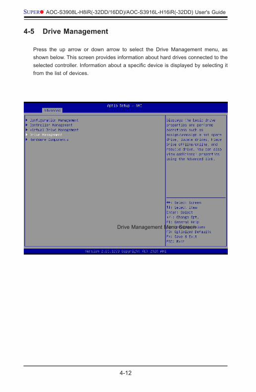
Press the up arrow or down arrow to select the Drive Management menu, as shown below. This screen provides information about hard drives connected to the selected controller. Information about a specific device is displayed by selecting it from the list of devices.
Drive Management Menu Screen
4-13
Chapter 4: Configuring the Broadcom MegaRAID Setting
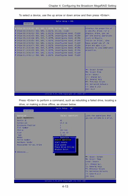
To select a device, use the up arrow or down arrow and then press <Enter>.
Press <Enter> to perform a command, such as rebuilding a failed drive, locating a drive, or making a drive offline, as shown below.
Drive Management Menu Screen
4-14
AOC-S3908L-H8iR(-32DD/16DD)/AOC-S3916L-H16iR(-32DD) User's Guide
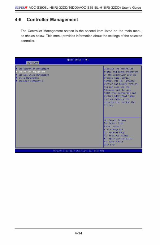
4-6 Controller Management
The Controller Management screen is the second item listed on the main menu, as shown below. This menu provides information about the settings of the selected controller.
4-15
Chapter 4: Configuring the Broadcom MegaRAID Setting
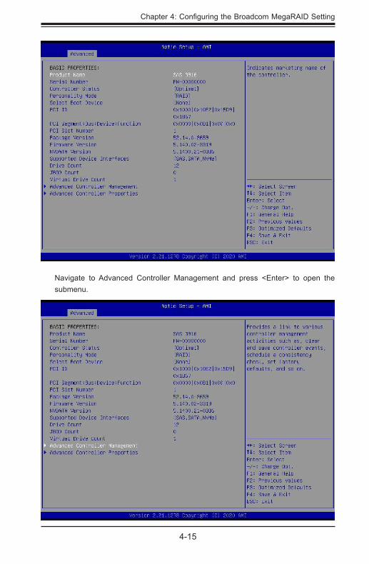
Navigate to Advanced Controller Management and press <Enter> to open the submenu.
4-16
AOC-S3908L-H8iR(-32DD/16DD)/AOC-S3916L-H16iR(-32DD) User's Guide
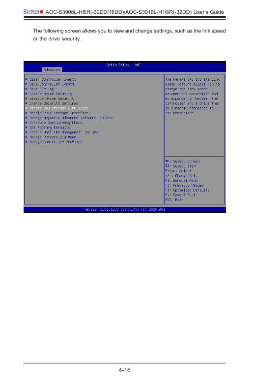
The following screen allows you to view and change settings, such as the link speed or the drive security.
4-17
Chapter 4: Configuring the Broadcom MegaRAID Setting
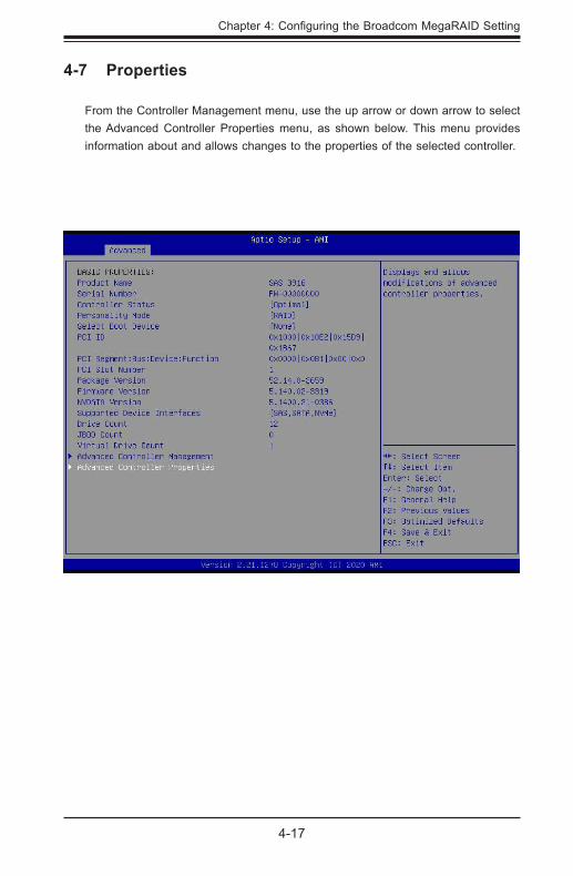
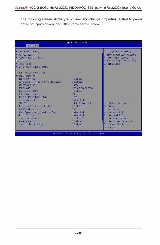
4-7 Properties
From the Controller Management menu, use the up arrow or down arrow to select the Advanced Controller Properties menu, as shown below. This menu provides information about and allows changes to the properties of the selected controller.
4-18
AOC-S3908L-H8iR(-32DD/16DD)/AOC-S3916L-H16iR(-32DD) User's Guide
The following screen allows you to view and change properties related to power save, hot spare drives, and other items shown below.
4-19
Chapter 4: Configuring the Broadcom MegaRAID Setting
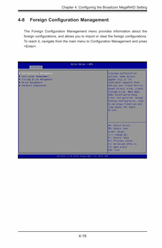
4-8 Foreign Configuration Management
The Foreign Configuration Management menu provides information about the foreign configurations, and allows you to import or clear the foreign configurations. To reach it, navigate from the main menu to Configuration Management and press <Enter>.
4-20
AOC-S3908L-H8iR(-32DD/16DD)/AOC-S3916L-H16iR(-32DD) User's Guide
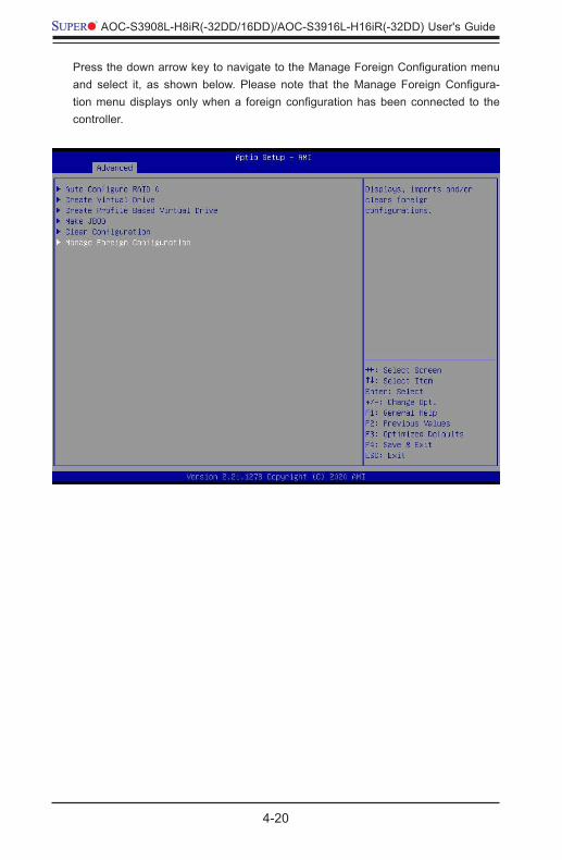
Press the down arrow key to navigate to the Manage Foreign Configuration menu and select it, as shown below. Please note that the Manage Foreign Configura-tion menu displays only when a foreign configuration has been connected to the controller.
4-21
Chapter 4: Configuring the Broadcom MegaRAID Setting
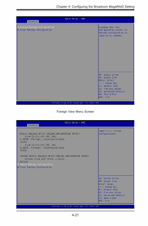
Foreign View Menu Screen
5-1
Chapter 5: MegaRAID Controller Firmware Update Procedures
Chapter 5
MegaRAID Controller Firmware Update Procedures
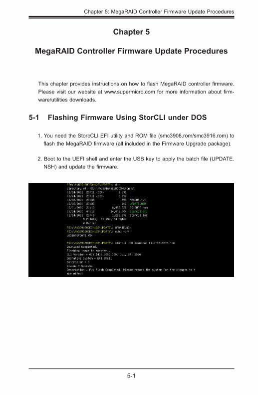
This chapter provides instructions on how to flash MegaRAID controller firmware. Please visit our website at www.supermicro.com for more information about firm-ware/utilities downloads.
5-1 Flashing Firmware Using StorCLI under DOS
1. You need the StorcCLI EFI utility and ROM file (smc3908.rom/smc3916.rom) to flash the MegaRAID firmware (all included in the Firmware Upgrade package).
2. Boot to the UEFI shell and enter the USB key to apply the batch file (UPDATE.NSH) and update the firmware.
5-2
AOC-S3908L-H8iR(-32DD/16DD)/AOC-S3916L-H16iR(-32DD) User's Guide
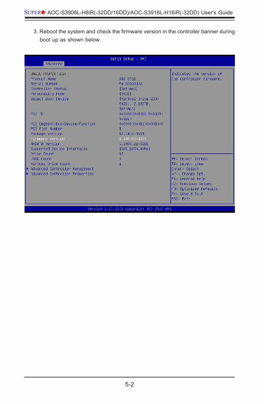
3. Reboot the system and check the firmware version in the controller banner during boot up as shown below.
5-3
Chapter 5: MegaRAID Controller Firmware Update Procedures
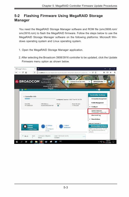
5-2 Flashing Firmware Using MegaRAID Storage Manager
You need the MegaRAID Storage Manager software and ROM file (smc3908.rom/smc3916.rom) to flash the MegaRAID firmware. Follow the steps below to use the MegaRAID Storage Manager software on the following platforms: Microsoft Win-dows operating system and Linux operating system.
1. Open the MegaRAID Storage Manager application.
2. After selecting the Broadcom 3908/3916 controller to be updated, click the Update Firmware menu option as shown below.
5-4
AOC-S3908L-H8iR(-32DD/16DD)/AOC-S3916L-H16iR(-32DD) User's Guide
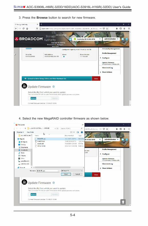
3. Press the Browse button to search for new firmware.
4. Select the new MegaRAID controller firmware as shown below.
5-5
Chapter 5: MegaRAID Controller Firmware Update Procedures
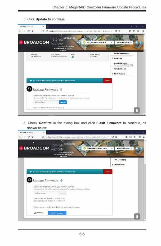
5. Click Update to continue.
6. Check Confirm in the dialog box and click Flash Firmware to continue, as shown below.
5-6
AOC-S3908L-H8iR(-32DD/16DD)/AOC-S3916L-H16iR(-32DD) User's Guide
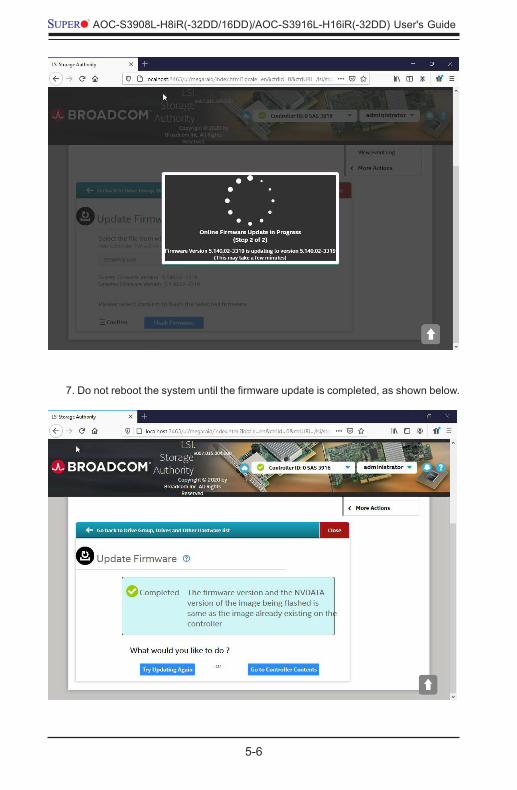
7. Do not reboot the system until the firmware update is completed, as shown below.
5-7
Chapter 5: MegaRAID Controller Firmware Update Procedures
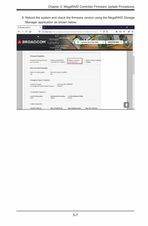
9. Reboot the system and check the firmware version using the MegaRAID Storage Manager application as shown below.
4-1
Chapter 6: Booting
Chapter 6
Booting
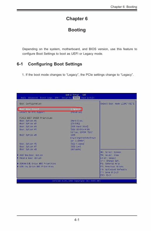
Depending on the system, motherboard, and BIOS version, use this feature to configure Boot Settings to boot as UEFI or Legacy mode.
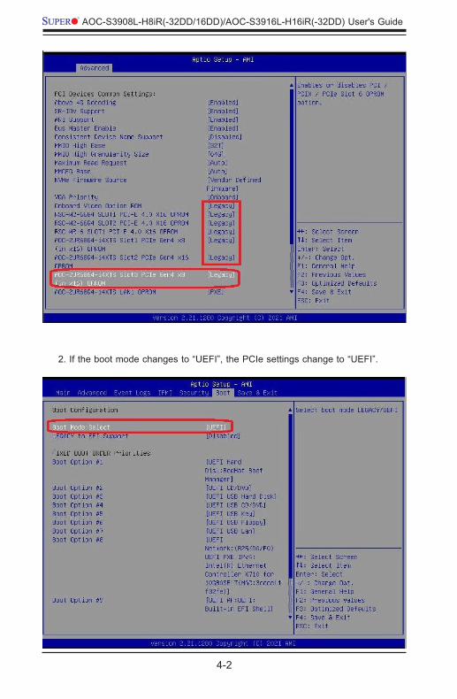
6-1 Configuring Boot Settings
1. If the boot mode changes to “Legacy”, the PCIe settings change to “Legacy”.
4-2
AOC-S3908L-H8iR(-32DD/16DD)/AOC-S3916L-H16iR(-32DD) User's Guide
2. If the boot mode changes to “UEFI”, the PCIe settings change to “UEFI”.
4-3
Chapter 6: Booting
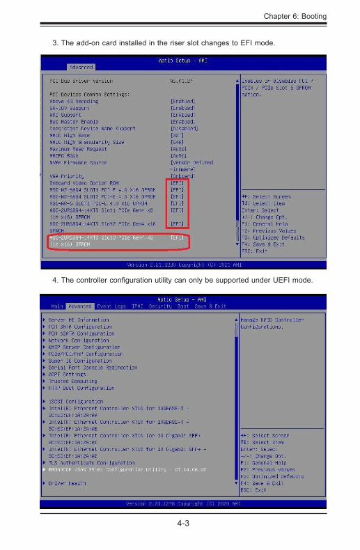
3. The add-on card installed in the riser slot changes to EFI mode.
4. The controller configuration utility can only be supported under UEFI mode.
4-4
AOC-S3908L-H8iR(-32DD/16DD)/AOC-S3916L-H16iR(-32DD) User's Guide
(Disclaimer Continued)
The products sold by Supermicro are not intended for and will not be used in life support systems, medical equipment, nuclear facilities or systems, aircraft, aircraft devices, aircraft/emergency com-munication devices, or other critical systems whose failure to perform be reasonably expected to result in significant injury or loss of life or catastrophic property damage. Accordingly, Supermicro dis-claims any and all liability, and should buyer use or sell such products for use in such ultra-hazardous applications, it does so entirely at its own risk. Furthermore, buyer agrees to fully indemnify, defend and hold Supermicro harmless for and against any and all claims, demands, actions, litigation, and proceedings of any kind arising out of or related to such ultra-hazardous use or sale.