Embed Size (px)
Citation preview

August 2015 © Amec Foster Wheeler Environment & Infrastructure UK Limited
Appendix 6.A Peat Management Plan

August 2015 © Amec Foster Wheeler Environment & Infrastructure UK Limited

E.ON Climate & Renewables UK Developments Ltd
Enoch Hill Wind Farm Peat Management Plan
July 2015
Amec Foster Wheeler Environment & Infrastructure UK Limited


3 © Amec Foster Wheeler Environment & Infrastructure UK Limited
July 2015 Doc Ref. 32965CGOS116i1r
Executive summary
Purpose of this report
This report has been produced to form the Peat Management Plan (PMP) for the construction phase of the proposed Enoch Hill Wind Farm. The PMP also considers site restoration works following construction of the wind farm.
The PMP presents details of the existing peat resources on site and the volumes of peat which will be temporarily stored / stockpiled, together with the indicative locations for on-site storage / stockpiling during the works.
Control measures are identified to protect peat during stripping and temporary storage / stockpiling activities. These control measures are also designed to ensure that stripped peat remains viable, throughout the construction works.
The quantities of peat to be used in reinstatement, together with the methods to be used for habitat reinstatement, are described.
A description is given of the requirement for in situ inspections at specific times during the construction phase and a stockpile inspection checklist is provided.
An auditing process is set out to ensure that the correct checks and inspections are carried out and that non-compliances are identified, reported and rectified. It is expected that the auditing process for recording peat conditions and stockpiling will form part of the Construction Environmental Management Plan (CEMP) for the construction phase. This will include peat stripping, stockpiling and restoration phasing plans and databases.
The PMP also describes the roles and responsibilities of individuals associated with the construction phase of work, including those of the Construction Contractor.

4 © Amec Foster Wheeler Environment & Infrastructure UK Limited
July 2015 Doc Ref. 32965CGOS116i1r

5 © Amec Foster Wheeler Environment & Infrastructure UK Limited
July 2015 Doc Ref. 32965CGOS116i1r
Contents
1. Introduction 7
2. Baseline Site and Peat Conditions 9
3. Potential Impacts on Peat during Construction 11
4. Proposed Construction Works and Quantitative Assessment of Peat Excavation Volumes 13
4.1 Key Elements of the Proposed Construction Works 13 4.2 Volumes of Peat to be stripped 13
5. Control Measures 15
5.1 Introduction 15 5.2 Measures for in-situ Peat Protection during Construction Works 15 5.3 Methods of Peat Stripping and Excavation 15 5.4 Methods of Temporary Peat Stockpiling 16
Temporary Storage of Surface Peat Turves 16 Temporary Storage of ‘Loose’ Sub-surface Peat 16
5.5 Temporary Peat Stockpiling 17 Locations of Temporary Peat Storage 17 Peat Storage Alongside Access Tracks 17 Peat Storage for Turbines, Crane Pads and Temporary Construction Compounds 18 Peat Storage for Borrow Pit Locations 18 Peat Storage for Control Building (including SPEN Substation) 18 General Principles for Temporary Peat Storage 18
5.6 Stockpile Footprint 18 5.7 Stockpile Inspection 19 5.8 Peat Reinstatement Methods 20 5.9 Balance of Excavated Peat Volume to Restored Peat Volume 21 5.10 Reinstatement of Different Habitat Types 21 5.11 Summary of Peat Handling and Replacement Methods 22
6. Monitoring and Inspection 23
6.1 Introduction 23 6.2 Failure to Meet Acceptability Criteria and Corrective Actions 23 6.3 Recording of Non-compliance and Corrective Actions 23
7. Quality Control and Audit Procedure 25
7.1 PMP Audit Procedure as Part of the CEMP 25 7.2 PMP Audit Procedure 25 7.3 Peat Stripping and Stockpiling Documentation and Plans 25

6 © Amec Foster Wheeler Environment & Infrastructure UK Limited
July 2015 Doc Ref. 32965CGOS116i1r
7.4 Scheduling of PMP Audit Activities and Reporting 25 7.5 Audit Checklist and Reporting 25 7.6 Reporting of Non-compliances 25 7.7 Criteria for Cessation of Works 26 7.8 Use of Tool Box Talks 26
8. Roles and Responsibilities 27
References 29
Table 4.1 Depths of Peat at Turbine Locations 13 Table 4.2 Total Volumes of Peat Stripped During Construction 14 Table 5.1 Summary of Stockpiling Method for ‘Dry’ Peat 16 Table 5.2 Indicative Depths of Peat to be used for Peat Reinstatement 20 Table 5.3 Indicative Excavated and Reused Volumes of Peat 21 Table 7.1 List of Example Tool Box Talks 26 Table 8.1 Summary of PMP Roles and Responsibilities 27 Table A.1 Peat Depths and Excavated Volumes at Each Turbine 1 Table A.2 Peat Depths and Excavated Volumes at Each Crane Pad 2 Table A.3 Peat Depths and Excavated Volumes for Construction Compound 2 Table A.4 Peat Depths and Excavated Volumes for the Substation 2 Table A.5 Peat Depths and Excavated Volumes at Permanent Met Masts 3 Table A.6 Peat Depths and Excavated Volumes at Borrow Pits 3 Table B.1 Soil Stockpile Inspection Checklist 1 Table C.1 Indicative Checklist for the Peat Management Plan 1
Figure 1 Site Layout After Page 8 Figure 2.1 Peat Depth Survey Data After Page 10 Figure 2.2 Peat Depth Survey Data After Page 10 Figure 2.3 Peat Depth Survey Data After Page 10 Figure 2.4 Peat Depth Survey Data After Page 10 Figure 2.5 Peat Depth Survey Data After Page 10 Figure 3 Interpolated Peat Contour Map After Page 12
Appendix A Soil Excavation Volumes for each Element of Infrastructure Appendix B Soil Stockpile Inspection Checklist Appendix C Indicative Audit Checklist for the Peat Management Plan

7 © Amec Foster Wheeler Environment & Infrastructure UK Limited
July 2015 Doc Ref. 32965CGOS116i1r
1. Introduction
E.ON Climate & Renewables UK Developments Ltd (“The Applicant”) is proposing to build a wind farm in East Ayrshire (named Enoch Hill Wind Farm - “the Proposed Development”), consisting of up to19 turbines, associated crane pads, access track, a substation and wind farm control building and transformers, a temporary construction compound and three borrow pit search areas.
The Proposed Development would be built on upland moorland located close to Loch Doon, between New Cumnock and Dalmellington, (herein referred to as the “Site”) (see Figure 1).
Peat is present within the Site and this report forms the Peat Management Plan (PMP) for the Proposed Development. It follows the general guidance provided in Scottish Renewables and SEPA (2012) ‘Developments on Peatland: Guidance on the Assessment of Peat Volumes, Reuse of Excavated Peat and the Minimisation of Waste’.
Construction activities have the potential to impact adversely upon both peat and peaty topsoils through excavation activities associated with constructing the foundations for turbine bases, crane pads, access tracks, the substation area, temporary construction compound and borrow pits.
The key aim of this PMP is to set out procedures to minimise excavated volumes of peat and protect peat resources as far as possible, thereby minimising carbon losses.
This PMP therefore identifies means to control and manage specifically the condition and quality of peat and peaty topsoil resources during construction so that they are maintained in a suitable condition for re-use within the Site. These include:
Procedures for peat and peaty topsoil stripping, handling, transporting, storing and restoration so as to maintain, as far as practicable, the condition of peat and peaty topsoils and their viability for reuse within the Site once construction has been completed; and
Control measures and a monitoring programme for the construction and post-construction land restoration phases of the Proposed Development.
This PMP specifically identifies:
The volumes of peat that will be excavated;
The capacity to reuse the peat on Site;
Peat handling procedures; and
Temporary storage and restoration.
The geographical scope of this PMP includes the area within the planning application boundary of the Proposed Development (see Figure 1).
It is expected that the PMP will form part of an overarching Construction Environmental Management Plan (CEMP) and will be used as a tool by environmental managers and site contractors as a method to control, record and audit environmental management activities relating to peat conditions and to ensure that peat and peaty topsoils remain in good condition for future re-use within the Site.
This PMP is structured as follows:
Section 1 provides an introduction;
Section 2 presents a summary of the baseline site and peat conditions;
Section 3 considers the potential impacts of construction works on peat;
Section 4 quantifies peat excavated volumes;
Section 5 describes a range of proposed control measures to avoid or minimise potential impacts on peat;

8 © Amec Foster Wheeler Environment & Infrastructure UK Limited
July 2015 Doc Ref. 32965CGOS116i1r
Section 6 provides a description of the peat monitoring programme, including locations, monitoring techniques, and acceptability criteria to be employed;
Section 7 proposes the auditing process and paperwork which will manage both the implementation of mitigation / monitoring and the assessment / review of monitoring data; and
Section 8 describes the roles and responsibilities for implementation of the PMP.

MM2
MM1T9
T8
T7
T6
T5
T4
T3
T2
T1
T19
T18
T17
T16
T15
T14
T13
T12
T11
T10
file
: H
: \P
roje
cts
\32
96
5 S
UB
Eno
ch
Hill
Win
d F
arm
EIA
\D0
40
\AR
CG
IS\3
296
5-G
la37
4.m
xd
Based upon the Ordnance Survey Map with the permission of the Controller of Her Majesty's Stationery Office. © Crown Copyright. 100027856. Aerial photography (c) Getmapping plc
Application Boundary
� Turbine locations
� Watercourse crossings
? Permanent meteorological masts
Proposed on site tracks
Turning Heads
Temporary Construction Compound
SPEN & EON Substation compound
Crane pads
Borrow pit search area
0 0.35 0.7 1.05 1.40.175
km
Key
Enoch Hill Wind FarmPeat Management Plan
Figure 1Site Layout
July 2015 32965-Gla374.mxd tim.doggett
1:25,000Scale at A3:
Client

9 © Amec Foster Wheeler Environment & Infrastructure UK Limited
July 2015 Doc Ref. 32965CGOS116i1r
2. Baseline Site and Peat Conditions
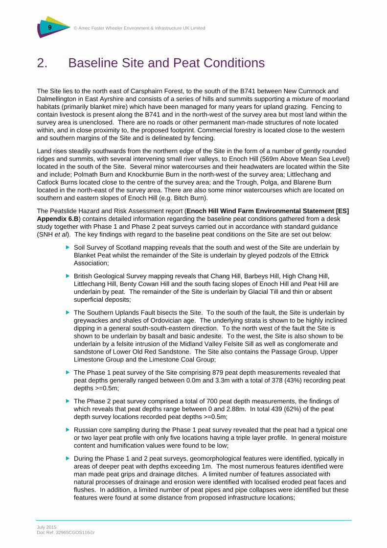
The Site lies to the north east of Carsphairn Forest, to the south of the B741 between New Cumnock and Dalmellington in East Ayrshire and consists of a series of hills and summits supporting a mixture of moorland habitats (primarily blanket mire) which have been managed for many years for upland grazing. Fencing to contain livestock is present along the B741 and in the north-west of the survey area but most land within the survey area is unenclosed. There are no roads or other permanent man-made structures of note located within, and in close proximity to, the proposed footprint. Commercial forestry is located close to the western and southern margins of the Site and is delineated by fencing.
Land rises steadily southwards from the northern edge of the Site in the form of a number of gently rounded ridges and summits, with several intervening small river valleys, to Enoch Hill (569m Above Mean Sea Level) located in the south of the Site. Several minor watercourses and their headwaters are located within the Site and include; Polmath Burn and Knockburnie Burn in the north-west of the survey area; Littlechang and Catlock Burns located close to the centre of the survey area; and the Trough, Polga, and Blarene Burn located in the north-east of the survey area. There are also some minor watercourses which are located on southern and eastern slopes of Enoch Hill (e.g. Bitch Burn).
The Peatslide Hazard and Risk Assessment report (Enoch Hill Wind Farm Environmental Statement [ES] Appendix 6.B) contains detailed information regarding the baseline peat conditions gathered from a desk study together with Phase 1 and Phase 2 peat surveys carried out in accordance with standard guidance (SNH et al). The key findings with regard to the baseline peat conditions on the Site are set out below:
Soil Survey of Scotland mapping reveals that the south and west of the Site are underlain by Blanket Peat whilst the remainder of the Site is underlain by gleyed podzols of the Ettrick Association;
British Geological Survey mapping reveals that Chang Hill, Barbeys Hill, High Chang Hill, Littlechang Hill, Benty Cowan Hill and the south facing slopes of Enoch Hill and Peat Hill are underlain by peat. The remainder of the Site is underlain by Glacial Till and thin or absent superficial deposits;
The Southern Uplands Fault bisects the Site. To the south of the fault, the Site is underlain by greywackes and shales of Ordovician age. The underlying strata is shown to be highly inclined dipping in a general south-south-eastern direction. To the north west of the fault the Site is shown to be underlain by basalt and basic andesite. To the west, the Site is also shown to be underlain by a felsite intrusion of the Midland Valley Felsite Sill as well as conglomerate and sandstone of Lower Old Red Sandstone. The Site also contains the Passage Group, Upper Limestone Group and the Limestone Coal Group;
The Phase 1 peat survey of the Site comprising 879 peat depth measurements revealed that peat depths generally ranged between 0.0m and 3.3m with a total of 378 (43%) recording peat depths >=0.5m;
The Phase 2 peat survey comprised a total of 700 peat depth measurements, the findings of which reveals that peat depths range between 0 and 2.88m. In total 439 (62%) of the peat depth survey locations recorded peat depths >=0.5m;
Russian core sampling during the Phase 1 peat survey revealed that the peat had a typical one or two layer peat profile with only five locations having a triple layer profile. In general moisture content and humification values were found to be low;
During the Phase 1 and 2 peat surveys, geomorphological features were identified, typically in areas of deeper peat with depths exceeding 1m. The most numerous features identified were man made peat grips and drainage ditches. A limited number of features associated with natural processes of drainage and erosion were identified with localised eroded peat faces and flushes. In addition, a limited number of peat pipes and pipe collapses were identified but these features were found at some distance from proposed infrastructure locations;

10 © Amec Foster Wheeler Environment & Infrastructure UK Limited
July 2015 Doc Ref. 32965CGOS116i1r
During the Phase 2 peat survey a relic peatslide and potential soil creep were identified approximately 135m northwest of T4 and in the general locality of T19, respectively;
In addition, numerous translational mineral soils slides were identified along the steep side slopes of the Littlechang Burn, Catlock Burn, Knockburnie Burn, Crocradie Burn and the Trough Burn.
The peat depth survey data and interpolated peat depth contour maps (Figures 2.1 to 2.5 and Figure 3) indicate that the majority of the Site has peat depths <1m deep.
There are two main areas containing peat >1.5m deep; one lies to the west of Littlechang Hill, whilst the other lies between Barbeys Hill and High Chang Hill. Elsewhere on the Site, areas of deeper peat >1.5m are confined to small pockets.
Approximately half of the Site consists of areas where peat is <0.5m and where mineral soils are likely to be found.
The layout of the Proposed Development has gone through a series of iterations to ensure that the infrastructure footprint lies, as far as is possible, outwith areas of peat >1m deep. Exceptions to this are the 8 turbines and borrow pit search area C listed in Table 4.1, whose footprints impinge wholly or partly on areas of peat >1m deep.

MM2
MM1T9
T8
T7
T6
T5
T4
T3
T2
T1
T19
T18
T17
T16
T15
T14
T13
T12
T11
T10
file
: H
: \P
roje
cts
\32
96
5 S
UB
Eno
ch
Hill
Win
d F
arm
EIA
\D0
40
\AR
CG
IS\3
296
5-G
la37
6.m
xd
Based upon the Ordnance Survey Map with the permission of the Controller of Her Majesty's Stationery Office. © Crown Copyright. 100027856.
Application Boundary
� Turbine locations
� Watercourse crossings
? Permanent meteorological masts
Proposed on site tracks
Borrow pit search areas
Turning Heads
Temporary Construction Compound
SPEN & EON Substation compound
Crane pads
Phase 1 and 2 Peat Depth Data (m)
0.00 - 0.50
0.50 - 1.00
1.00 - 1.50
1.50 - 2.00
2.00 - 2.50
2.50 - 3.00
3.00 - 3.50
0 0.3 0.6 0.9 1.20.15
km
Key
Enoch Hill Wind FarmPeat Management Plan
Figure 2.1Peat Depth Survey Data
July 2015 32965-Gla376.mxd tim.doggett
1:22,500Scale at A3:
Client

0m
0m
0m
0m
0m
0m
0m
0m
0m
0m 0m0m
0m0m
0m0m0m
0m0m
0m 0m 0m
0m
0m
0m 0m 0m 0m 0m 0m
1m
1m
1m
0m
0m
0m
0m0m
0m
0m0m0m
0m1m0m
0m1m0m
2m
0m
0m0m0m
0m 0m 0m
1m0m
0m
0m
0m
0m
0m
0m
0m
0m
0m
0m
0m0m
0m
0m
0m 0m 1m 0m 0m 0m 0m 0m
0m0m0m0m0m0m0m
0m 0m 0m
0m0m
0m 0m
0m
0m
0m0m
0m
0m
0m
0m
0m
0m 0m0m
0.9m
0.6m
0.4m 0.4m
0.3m
0.4m0.4m0.3m0.5m
0.4m0.4m
0.6m
0.4m
0.4m
0.3m
0.9m
0.6m
0.9m0.9m
0.3m
0.6m
0.6m
0.3m
1.3m
0.5m
0.8m 1.9m
0.2m
0.3m0.4m
0.3m0.3m0.4m0.3m
0.3m
0.3m
0.5m 0.4m 0.4m 0.4m
0.8m0.3m0.4m0.4m0.4m0.4m
0.3m
0.4m
0.9m0.4m
0.3m
0.3m0.3m 0.3m
1.1m
0.2m0.7m0.7m
0.5m
0.5m
0.5m
0.8m
0.3m0.3m
0.3m
0.5m
0.5m 0.2m 0.9m 0.9m 0.3m
0.2m
0.3m 0.3m
0.5m0.1m0.1m0.2m
0.1m
0.3m
0.2m0.3m
0.3m
0.4m
0.2m
0.2m
0.4m0.9m
0.6m
0.2m
0.3m
0.5m
0.4m
0.7m
1.1m
0.4m0.2m
0.3m
0.2m
0.3m
0.3m0.6m
0.9m
0.2m
0.2m
0.3m
0.8m
0.4m
0.7m
0.4m
0.7m
0.7m
1.3m
0.7m
0.9m
0.3m
0.3m
0.3m 0.4m 0.3m 0.7m 0.7m
0.9m1.7m1.8m
0.8m 3.3m
0.6m2.2m0.4m
0.3m
0.3m
0.7m
1.3m
1.2m0.3m
0.3m
0.3m0.3m
0.3m 0.4m
0.2m
0.2m
0.6m0.2m0.2m
0.3m
0.4m
0.9m
0.1m
0.1m
0.4m
0.4m
0.45m0.34m
0.41m
0.24m
0.44m 0.57m0.44m
1.62m0.99m
0.43m
1.02m
0.61m
0.63m 0.57m
0.26m
0.65m0.59m
1.33m
0.31m
0.35m
0.75m
0.45m
0.85m
0.75m
0.37m
0.53m
0.39m
0.45m0.78m
0.45m 0.85m 0.73m
0.52m0.35m0.18m
0.05m
0.15m
0.01m
0.01m
0.01m0.15m
0.52m
0.35m0.15m 0.05m
0.24m
0.62m0.23m
0.46m 0.46m
0.25m0.32m
0.75m
0.21m
0.25m
0.45m
0.45m
0.29m
0.28m0.37m
0.43m
0.67m0.24m
0.87m
file
: H
:\P
roje
cts
\32
96
5 S
UB
En
och
Hill
Win
d F
arm
EIA
\D0
40
\AR
CG
IS\3
296
5-G
la37
7.m
xd
Based upon the Ordnance Survey Map with the permission of the Controller of Her Majesty's Stationery Office. © Crown Copyright. 100027856.
Application Boundary
� Turbine locations
� Watercourse crossings
? Permanent meteorological masts
Proposed on site tracks
Borrow pit search areas
Turning Heads
Temporary Construction Compound
SPEN & EON Substation compound
Crane pads
Phase 1 and 2 Peat Depth Data (m)
0.00 - 0.50
0.50 - 1.00
1.00 - 1.50
1.50 - 2.00
2.00 - 2.50
2.50 - 3.00
3.00 - 3.50
0 0.1 0.2 0.3 0.40.05
km
Key
Enoch Hill Wind FarmPeat Management Plan
Figure 2.2Peat Depth Survey Data
July 2015 32965-Gla377.mxd tim.doggett
1:7,500Scale at A3:
Client
9.5

0m
0m
0m
0m
0m
0m
0m
0m
0m 0m
0m
1m0m
1m
1m
0m
2m
0m
1m
1m
1m
0m
0m
0m
0m
2m
0m
0m0m
0m
0m
0m
0m
0m
0m0m
0m
0m
0m
2m
0m
0m
0m
0m
0m1m0m
0m1m
1m
0m
0m
0m
2m
0m
0m0m0m0m
0m
0m
0m
0m
0m
0m
0m
0m
0m
0m
0m
0m
0m
0m
0m
2m
1m
0m
0m
0m
0m
1.6m
2.4m
2.3m
0.6m1.6m
1.2m0.9m
1.1m
0.6m0.5m
0.5m
0.7m
0.5m
0.9m
0.4m 0.4m
0.3m
0.4m0.4m0.3m0.5m
0.6m 0.5m 0.4m
0.3m
0.3m1.1m
0.9m
0.6m
0.4m1.3m
0.9m0.9m
0.4m
0.4m
0.6m0.5m
0.5m0.9m
1.7m
1.3m0.5m
0.7m
0.9m
0.9m0.9m
0.9m1.7m
1.8m0.8m
0.9m1.1m
0.5m
1.1m
0.5m
0.7m0.4m
0.7m0.7m
0.5m
0.9m
0.9m
0.6m
0.5m
0.4m
0.4m
0.6m
0.5m
0.9m0.3m0.9m
0.6m
0.6m
0.5m
0.6m
0.5m
0.9m
0.3m
0.3m
0.5m
0.7m
0.4m
0.6m
0.4m
0.4m
0.3m
0.9m
0.6m
0.9m0.9m
0.3m
0.6m
2.7m
0.5m
1.8m
1.1m
0.2m0.7m0.7m
0.5m
0.5m
0.5m
0.8m
0.3m0.3m
0.3m
0.3m
0.2m
0.2m
0.5m
0.1m
0.7m
1.7m
2.1m
0.6m1.8m
1.3m
0.6m
0.5m
0.5m
0.3m
0.2m
0.3m
1.7m
1.7m
0.4m
0.8m
0.3m
0.3m
1.2m0.4m
0.6m
0.9m
0.5m
1.3m
0.2m
0.9m
0.7m
0.3m
0.3m
0.4m
0.2m
0.2m
0.4m0.9m
0.6m
0.2m
0.3m
0.5m
0.4m
0.3m
1.1m
0.4m
1.1m
1.4m
1.4m
1.2m
0.2m
0.4m
0.4m
1.7m
0.4m
1.1m
0.6m
1.1m
0.6m
1.7m
0.7m
0.2m
0.3m
0.4m
0.7m
1.1m
0.4m0.2m
0.3m
0.2m
0.3m
0.3m
0.6m
0.3m
0.9m
0.3m
1.6m
0.4m
1.8m
1.7m
1.4m
1.1m
0.6m
0.2m
0.6m
0.2m
0.3m
0.6m
0.9m
0.2m
0.2m
0.3m
0.8m
0.4m
0.7m
0.4m
0.7m
0.7m
0.7m
0.9m
0.2m
1.7m
0.1m
0.2m
0.2m
0.3m
1.1m
0.4m
0.4m
1.8m
1.3m
0.7m
0.9m
0.3m
0.3m
0.3m 0.4m 0.3m 0.7m 0.7m
0.9m1.7m1.8m
0.3m
0.7m
1.3m
1.2m
1.3m
0.4m
1.7m
0.3m
0.3m
0.8m
0.6m
0.8m
0.4m
0.1m
0.1m
0.4m
1.1m
1.1m
0.9m
0.9m
0.7m
0.4m
0.3m
0.6m
1.3m
0.1m
1.1m
1.7m
1.1m
1.7m
0.4m0.3m
2.6m
0.4m
0.7m
1.4m
1.5m
0.2m
0.3m
0.4m
0.5m
0.1m
0.1m
0.5m
0.8m
1.1m
0.3m
0.3m
0.3m
2.5m0.9m
0.5m
0.1m
1.4m
0.6m
1.7m
0.4m
0.6m
0.5m
0.4m
0.4m
0.4m
0.57m0.84m1.81m
2.13m
2.88m
1.86m
1.49m
0.38m0.28m
0.65m0.91m
1.11m
0.73m
0.66m
0.72m
1.06m
1.52m
0.93m
0.81m
1.66m
1.38m
0.37m1.67m
0.98m
1.35m0.98m
0.79m
0.81m
2.27m2.44m1.61m
0.64m0.88m0.29m0.59m
1.07m0.66m
0.52m
0.34m
0.52m
0.45m0.34m
0.41m
0.24m
0.44m 0.57m0.44m
1.62m0.99m
0.43m
1.02m
0.61m
0.35m
0.75m
0.85m
0.85m
0.85m
0.45m
0.85m
0.46m
0.78m
0.86m
0.56m
0.86m
0.84m
0.73m0.44m
0.33m
0.44m
0.47m
0.35m
0.82m
1.85m
0.37m
0.53m
0.39m
0.45m
0.25m
0.45m
0.45m
0.45m
0.45m
0.15m
0.23m
0.63m
0.68m
0.74m
0.54m
0.58m
1.05m
0.39m
1.01m
0.51m
0.74m
0.57m
0.89m
0.31m
0.43m
1.36m
1.77m
1.49m
0.61m
0.78m
0.71m
0.39m
0.37m
0.29m
0.28m0.37m
0.43m
0.67m
0.35m
0.41m
1.72m
1.23m
0.79m
1.11m
0.45m
0.45m
0.85m
0.54m
0.38m
0.61m
0.58m
0.84m
0.95m
0.44m
0.48m
0.25m
0.47m
0.24m
0.87m
0.48m
0.55m
T5
T3
T1
file
: H
: \P
roje
cts
\32
96
5 S
UB
Eno
ch
Hill
Win
d F
arm
EIA
\D0
40
\AR
CG
IS\3
296
5-G
la37
8.m
xd
Based upon the Ordnance Survey Map with the permission of the Controller of Her Majesty's Stationery Office. © Crown Copyright. 100027856.
Application Boundary
� Turbine locations
� Watercourse crossings
? Permanent meteorological masts
Proposed on site tracks
Borrow pit search areas
Turning Heads
Temporary Construction Compound
SPEN & EON Substation compound
Crane pads
Phase 1 and 2 Peat Depth Data (m)
0.00 - 0.50
0.50 - 1.00
1.00 - 1.50
1.50 - 2.00
2.00 - 2.50
2.50 - 3.00
3.00 - 3.50
0 0.1 0.2 0.3 0.40.05
km
Key
Enoch Hill Wind FarmPeat Management Plan
Figure 2.3Peat Depth Survey Data
July 2015 32965-Gla378.mxd tim.doggett
1:7,500Scale at A3:
Client
9.5

1m
1m
0m
2m
0m
0m
0m0m
2m
1m
0m
0m
1m
0m
0m
0m
1m
0m
1m
0m
0m
0m
2m
2m
1m1m
1m
0m
0m
1m
1m
2m
2m
0m
2m
0m
2.1m
1.9m 0.6m
1.4m
0.9m
2.3m2.4m2.1m
2.2m
1.3m
1.8m2.3m
1.7m1.4m0.5m1.9m
0.9m
2.2m2.3m
1.4m1.5m
0.8m
0.2m
0.7m
0.5m
0.7m
1.6m
1.1m
0.4m
0.1m0.2m
0.6m
0.4m
0.5m
1.2m
1.2m
0.9m
1.3m
0.9m
0.9m0.9m
0.9m1.7m
1.8m0.8m
0.9m1.1m
0.5m
1.1m
0.5m
0.7m0.4m
0.7m0.7m
0.5m
0.9m
0.9m
0.6m
0.5m
0.4m
0.4m
0.3m
0.3m
1.7m1.7m
0.5m
0.6m
1.3m0.9m
0.6m
0.3m
0.7m
0.9m
0.9m
0.6m
0.6m
0.8m1.1m
0.8m
0.5m
0.3m
0.5m
0.3m
0.5m
0.4m0.6m
2.3m1.3m
2.4m1.5m0.6m
0.7m
0.8m1.3m
0.9m
0.4m
0.7m1.1m
0.6m0.9m0.6m0.3m
0.6m
0.6m
0.5m
0.9m0.3m0.9m
0.6m
0.6m
0.5m
0.6m
0.5m
0.5m
2.7m
0.5m
0.3m
0.5m
0.3m
0.6m
0.3m
0.4m
0.4m
0.7m
0.1m
1.1m
0.2m
0.3m
0.3m
0.9m
0.5m
0.4m0.5m
0.1m
0.7m
1.7m
2.1m
0.6m
0.3m
0.4m
0.9m
0.6m
0.9m
0.4m
0.4m
0.7m
1.1m
1.6m
2.2m0.4m
0.4m
0.6m
0.3m
0.4m
0.3m
0.1m
1.8m
1.3m
0.6m
0.5m0.4m
0.8m
0.3m
0.3m
1.2m
2.6m
2.7m
1.2m
0.2m
0.4m
1.1m
0.6m
0.3m
0.7m
1.5m
0.2m
0.2m
0.6m
1.7m
0.3m
0.4m
0.6m
0.9m
0.5m1.2m
0.2m
0.4m
0.4m
2.2m
1.7m
0.4m
1.1m
0.6m
1.1m0.4m
1.8m
1.7m
1.4m
1.1m0.2m
0.6m
0.5m
0.4m
1.1m
1.8m
0.9m
0.6m
1.1m
0.8m
0.2m
0.3m
0.5m
0.2m
0.9m
0.2m
0.1m
1.1m
0.3m
0.9m
0.4m
0.5m0.1m
1.1m
1.7m
1.1m
1.7m
0.4m
0.1m
0.3m
0.5m
0.5m
0.6m
1.6m
2.1m
0.3m
0.7m
1.1m
1.5m
1.1m
0.7m
1.1m
1.1m
0.5m
0.5m
0.2m
1.6m
0.5m
0.7m
0.8m
0.2m
0.3m
2.6m
0.4m
0.7m
1.4m
0.3m
0.3m
0.3m
2.5m
1.4m
0.5m
0.6m
0.1m
0.1m
0.4m
0.7m
0.7m
1.1m
1.1m
0.6m
0.1m
0.8m
0.6m
0.5m
0.8m
0.3m
0.4m
0.7m
1.8m
0.9m
0.5m
0.1m
1.4m
0.6m
1.7m
1.75m
0.28m
0.45m0.94m
0.94m
0.65m
0.85m
0.94m
0.54m
0.62m
0.56m
0.58m
0.57m0.84m1.81m
2.88m
0.44m
0.62m0.49m
0.63m
0.84m
0.39m
0.58m0.92m
0.41m
0.41m
0.77m
0.17m
0.39m
0.27m
0.69m
0.56m0.21m
0.19m
0.18m
0.39m
0.22m
0.48m
0.26m
0.44m
0.36m
0.39m
0.23m
0.61m
0.92m
0.94m
0.65m1.13m
1.35m
1.26m1.67m
1.13m
0.85m
0.85m
0.85m
0.45m
0.65m
0.44m
0.13m
0.17m
0.46m
0.78m
0.86m
0.56m
0.86m
0.84m
0.73m0.44m
0.33m
0.44m
0.47m
0.35m
0.82m
0.45m
0.45m
0.45m
0.45m
0.45m
0.45m
0.39m
1.01m
0.51m
0.74m
0.57m
1.44m
1.84m
0.36m
1.96m1.42m
0.31m
0.36m
0.86m
1.08m
0.49m
0.49m
0.89m
0.31m
0.43m
1.36m
1.77m
1.49m
1.11m
0.45m
0.45m
0.44m
0.34m
1.96m
1.96m
0.47m
0.39m
0.95m
2.34m
0.85m
0.54m
0.38m
0.61m
0.58m
0.84m
0.48m
0.72m
0.75m
MM2
T5
T4
T3
T1
file
: H
: \P
roje
cts
\32
96
5 S
UB
Eno
ch
Hill
Win
d F
arm
EIA
\D0
40
\AR
CG
IS\3
296
5-G
la37
9.m
xd
Based upon the Ordnance Survey Map with the permission of the Controller of Her Majesty's Stationery Office. © Crown Copyright. 100027856.
Application Boundary
� Turbine locations
� Watercourse crossings
? Permanent meteorological masts
Proposed on site tracks
Borrow pit search areas
Turning Heads
Temporary Construction Compound
SPEN & EON Substation compound
Crane pads
Phase 1 and 2 Peat Depth Data (m)
0.00 - 0.50
0.50 - 1.00
1.00 - 1.50
1.50 - 2.00
2.00 - 2.50
2.50 - 3.00
3.00 - 3.50
0 0.1 0.2 0.3 0.40.05
km
Key
Enoch Hill Wind FarmPeat Management Plan
Figure 2.4Peat Depth Survey Data
July 2015 32965-Gla379.mxd tim.doggett
1:7,500Scale at A3:
Client
9.5

1m
1m
0m
0m
0m0m
2m
1m
1m
1m0m
0m
0m
1m
0m
0m
0m
1m
0m
0m
0m
0m0m
0m
0m
0m0m
0m0m
1m
1m
1m
2m
0m
0.7m0.9m
0.9m
0.4m
0.9m
0.5m
0.7m
1.6m
0.4m
0.6m0.5m
0.5m0.9m
1.7m
1.3m0.5m
0.7m
0.9m
0.9m0.9m
0.9m1.7m1.8m
0.3m
0.3m
1.7m1.7m
0.5m
0.6m
1.3m0.9m
0.6m
0.3m
0.7m
0.9m
0.9m
0.6m
0.6m
0.8m1.1m
0.8m
0.5m
0.3m
0.5m
0.3m
0.5m
0.4m0.6m
2.3m1.3m
2.4m1.5m0.6m
0.7m
0.8m1.3m
0.9m
0.4m
0.7m1.1m
0.6m
0.5m
0.7m
0.1m
2.2m2.2m
0.1m
0.9m
0.9m
1.2m
0.3m0.3m
0.3m
0.1m 0.5m 0.1m
0.8m0.9m0.1m1.2m0.5m1.3m
0.4m
1.5m
0.6m
1.3m 1.2m 0.3m
0.9m0.3m0.7m0.1m
0.1m
1.7m
0.2m 0.5m
0.4m0.8m
1.7m
0.3m
0.5m
0.3m
0.6m
0.3m
0.4m
0.4m
0.7m
0.1m
1.1m
0.2m
0.3m
0.3m
0.9m
0.5m
0.4m
0.3m
0.2m
0.1m0.4m
0.2m
1.1m
0.1m
0.1m
0.9m
0.7m
0.1m
0.1m
2.4m
1.2m
0.6m
0.5m
1.4m
1.8m
0.1m
0.4m
1.7m
1.8m1.2m
0.4m
0.2m0.9m
0.4m 0.2m
0.2m
0.1m
0.1m
0.1m
0.2m
0.2m
0.2m
0.4m
1.4m
0.5m0.7m1.2m
0.9m
0.6m
1.1m
0.8m
0.2m
0.3m
0.5m
0.2m
0.9m
0.2m
0.1m
1.1m
0.3m
0.9m
0.4m
0.5m
0.6m
0.6m0.6m
1.3m
0.1m
1.1m
1.7m
1.1m
1.7m
0.4m
0.1m
0.3m
0.5m
0.5m
0.6m
1.6m
2.1m
0.3m
0.7m
1.1m
0.28m
0.45m0.94m
0.94m
0.65m
0.85m
0.94m
0.54m
0.45m
0.52m
0.96m
0.22m0.18m
0.66m0.99m
0.55m1.94m
0.74m0.93m
0.69m0.88m
0.91m
0.49m
0.66m0.15m
0.75m
0.54m
0.82m
0.64m0.82m
0.38m0.82m 0.61m
0.61m0.79m0.35m
0.39m
0.28m
0.41m
0.32m
0.62m
0.56m
0.58m
0.57m0.84m1.81m
0.44m
0.62m
0.63m
0.85m
0.65m
0.44m
0.32m
0.13m
0.25m
0.69m
0.17m
0.41m
0.22m
0.54m
0.15m
0.37m
0.38m0.35m
0.85m
0.81m
1.17m
0.12m
0.17m0.55m
1.02m
0.86m 0.46m
0.48m 0.95m
0.85m
0.64m
1.22m
0.68m
0.92m
0.71m
1.65m
1.34m
0.93m
0.82m
1.15m
0.25m
1.16m
0.49m
0.25m0.15m
0.25m0.85m
0.45m
0.25m 0.15m 0.35m
0.75m 0.48m
1.15m
0.25m
0.75m0.35m
0.45m
0.55m 0.47m
0.35m 0.25m
0.45m
0.63m
0.55m
0.45m
0.33m
0.86m
0.46m
0.53m
0.48m
0.86m
1.53m
0.87m
0.95m
0.66m
1.02m
0.69m
0.98m
0.39m
0.77m
0.52m
0.76m
0.53m
0.51m
0.27m
0.29m
0.82m
0.94m
0.58m
1.05m
0.39m
1.01m
0.51m
0.74m
0.57m
1.44m
1.84m
0.36m
1.96m1.42m
0.31m
0.36m
0.86m
1.08m
0.49m
0.49m
0.89m
0.31m
0.43m
1.36m
1.77m
1.49m
0.61m
1.45m
0.75m
1.15m
0.85m
0.72m
0.74m0.82m
0.82m
0.54m
2.45m
0.58m
0.86m
1.35m
0.48m
0.45m
0.48m
0.42m
0.44m
0.35m
0.62m0.85m0.48m
0.84m 0.35m
0.86m
0.35m
0.28m0.44m0.98m
T18
T14
T13
T12
file
: H
: \P
roje
cts
\32
96
5 S
UB
Eno
ch
Hill
Win
d F
arm
EIA
\D0
40
\AR
CG
IS\3
296
5-G
la38
0.m
xd
Based upon the Ordnance Survey Map with the permission of the Controller of Her Majesty's Stationery Office. © Crown Copyright. 100027856.
Application Boundary
� Turbine locations
� Watercourse crossings
? Permanent meteorological masts
Proposed on site tracks
Borrow pit search areas
Turning Heads
Temporary Construction Compound
SPEN & EON Substation compound
Crane pads
Phase 1 and 2 Peat Depth Data (m)
0.00 - 0.50
0.50 - 1.00
1.00 - 1.50
1.50 - 2.00
2.00 - 2.50
2.50 - 3.00
3.00 - 3.50
0 0.1 0.2 0.3 0.40.05
km
Key
Enoch Hill Wind FarmPeat Management Plan
Figure 2.5Peat Depth Survey Data
July 2015 32965-Gla380.mxd tim.doggett
1:7,500Scale at A3:
Client
9.5


11 © Amec Foster Wheeler Environment & Infrastructure UK Limited
July 2015 Doc Ref. 32965CGOS116i1r
3. Potential Impacts on Peat during Construction
Principal types of adverse effect that could potentially occur due to the Proposed Development are as follows:
Loss of structural integrity and peat strength, due to stripping off or damaging the surface vegetation turf, excavation, handling and transporting peat, particularly wet, subsurface peat;
Erosion and gullying, caused by exposure of bare peat surfaces – primarily caused by water erosion, due to surface runoff after rainfall;
Contamination, caused by leaks, spillages or inappropriate laydown of materials;
Peatslide, caused by laying wet peat on top of wet peat, laying other heavy materials (including excavated mineral soil or other construction materials) on top of wet peat or by inappropriate stockpiling, such as attempting to create stockpiles of peat that are too high, without bunding, engineering or geotechnical support;
Interruption of peat hydrology due to construction activities leading to a potential indirect adverse effect upon better quality blanket bog vegetation.
A range of methods and control measures are described in Section 5 of this PMP which are designed to prevent these effects from occurring.

12 © Amec Foster Wheeler Environment & Infrastructure UK Limited
July 2015 Doc Ref. 32965CGOS116i1r

MM2
MM1T9
T8
T7
T6
T5
T4
T3
T2
T1
T19
T18
T17
T16
T15
T14
T13
T12
T11
T10
file
: H
: \P
roje
cts
\32
96
5 S
UB
Eno
ch
Hill
Win
d F
arm
EIA
\D0
40
\AR
CG
IS\3
296
5-G
la38
1.m
xd
Based upon the Ordnance Survey Map with the permission of the Controller of Her Majesty's Stationery Office. © Crown Copyright. 100027856. Aerial photography (c) Getmapping plc
Application Boundary
� Turbine locations
� Watercourse crossings
? Permanent meteorological masts
Proposed on site tracks
Turning Heads
Temporary Construction Compound
SPEN & EON Substation compound
Crane pads
Borrow pit search areas
Interpolated Peat Depth (m)
0 - 0.5
0.5 - 1.0
1.0 - 1.5
1.5 - 2.0
2.0 - 2.5
2.5 - 3.0
3.0 - 3.5
0 0.3 0.6 0.9 1.20.15
km
Key
Enoch Hill Wind FarmPeat Management Plan
Figure 3Interpolated Peat Depth Contour Map
July 2015 32965-Gla381.mxd tudoa
1:22,500Scale at A3:
Client


13 © Amec Foster Wheeler Environment & Infrastructure UK Limited
July 2015 Doc Ref. 32965CGOS116i1r
4. Proposed Construction Works and QuantitativeAssessment of Peat Excavation Volumes
4.1 Key Elements of the Proposed Construction Works
The key elements of the Proposed Development are as follows:
Construction of up to 19 wind turbine generators, with a blade tip height of up to 130m;
Construction of one crane hard standing at each turbine;
Construction of approximately 12.9km of new onsite access tracks, approximately 1.9km of which will be constructed as floating roads;
Construction of an on-site wind farm control building (and Scottish Power Energy Networks (SPEN) substation);
Temporary construction compounds; and
Borrow pit(s) for the extraction of stone.
The dimensions and description of all infrastructure are provided in Chapter 4 of the Enoch Hill Wind Farm ES and are summarised in Table 4.2 below.
It is anticipated that the Proposed Development will take approximately 12 months to construct.
Construction activities which have the potential to impact on peat include:
Stripping and temporary storage of peat, including organic surface horizons and vegetation turf;
Trafficking of heavy plant and vehicles across areas consisting of peat and organic surface horizons and vegetation turf;
Laydown of materials (including excavated peat and mineral soil) on peat and peatland vegetation; and
Reinstatement of peat, organic surface horizons and vegetation turf and other re-vegetation activities to reinstate pre-construction peatland and heathland habitats.
4.2 Volumes of Peat to be stripped
Of the 19 turbines and associated crane pads, 13 are located in peat that is >0.5m deep (eight are located in areas where peat >1m deep). The remaining six turbines are located in areas where average material depth varies from 0.15m to 0.44m (i.e. not peat). This is summarised in Table 4.1.
Table 4.1 Depths of Peat at Turbine Locations
Peat Depth No Turbines Turbine Locations
Turbines with excavated material <0.5m deep
6 T1, T6, T10, T11, T14, T18
Turbines with peat between 0.5m and 1m deep
5 T3, T5, T8, T9, T12
Turbines with peat >1m 8 T2, T4, T7, T13, T15, T16, T17, T19

14 © Amec Foster Wheeler Environment & Infrastructure UK Limited
July 2015 Doc Ref. 32965CGOS116i1r
Table 4.2 provides an assessment of the total volumes of peat which will be stripped during the construction works. A breakdown of volumes of peat stripped per element of infrastructure is provided in Appendix A.
Table 4.2 Total Volumes of Peat Stripped During Construction
Infrastructure Dimensions Total Peat Volume (m3)
Turbine bases x 13 Each = 25m square* 12,285
Crane pads x 12 Each = 50m x 25m** 13,813
New (cut) access track (peat between 0.5m and 1m deep)
6.15km x 6m 26,286
New (cut) access track (material <0.5m deep) 4.75km x 6m 0
Floating track (peat >1m deep) 1.9km 0
Passing places along access tracks 25 x (30m x 6m) 2,550
Control building compound (including SPEN Substation)
180m x 110m 12,276
Two permanent met masts Each = 5 x 5m foundation + 20 x 20m crane pad 332
Construction compound 100m x 100m 5,100
Borrow pits x 3 Various (total 50,000m2) 10,500
TOTAL 83,142
*The foundation dimensions are a maximum of 25m x 25m. The excavated dimensions have been assumed to be 27.5 toallow for batters at the edges. In accordance with previous advice from SEPA turbines in peat <0.5m are not included in the peat volume in Table 4.2. However, the volume of peat <0.5m deep that will require to be excavated has been calculated within Appendix A in recognition of the fact that it will need to be stripped, handled, segregated from mineral soil and stockpiled in exactly the same way as deeper peat.
** The footprint area of crane pads used for the calculation of excavated peat has assumed a dimension of 50m x 25m in all areas of peat >0.5m. In accordance with previous advice from SEPA hardstandings in peat <0.5m are not included in the peat volume in Table 4.2. However, the volume of peat <0.5m deep that will require to be excavated has been calculated within Appendix A in recognition of the fact that it will need to be stripped, handled, segregated from mineral soil and stockpiled in exactly the same way as deeper peat..
Calculation of stripped and excavated peat has been made using averages of the peat depths within infrastructure footprints which were gathered during the Phase 1 and Phase 2 peat surveys (please see Appendix A).

15 © Amec Foster Wheeler Environment & Infrastructure UK Limited
July 2015 Doc Ref. 32965CGOS116i1r
5. Control Measures
5.1 Introduction
Care must be taken throughout all peat handling, transporting and stockpiling activities to protect and conserve the peat structure and strength as far as possible.
The purpose of this section of the PMP is to describe how the management of peat will be controlled and to specify how peat will be protected and peat integrity conserved throughout all stages of the construction works.
5.2 Measures for in-situ Peat Protection during Construction Works
The layout of the wind farm has already taken into account constraints relating to sensitive areas. The wind farm layout and access track route will be marked on an Access Plan and will be demarcated on the ground by temporary fencing and off-road tracking of heavy plant will not be permitted outside the demarcated area.
The Access Plan and the route of the access track will provide a designated controlled route and a permissible corridor within which service vehicles and plant can operate prior to peat and topsoil stripping. The purpose of the Access Plan is to protect in situ peat in areas that are not affected by the wind farm development and to prevent unnecessary vehicle and plant tracking across these areas. The following rules will apply to the Access Plan:
There will be no vehicle access to areas of the Site outside the area marked on the Access Plan (the wind farm layout marked on the plan);
There will be no stopping of vehicles outside the area marked on the Access Plan;
Servicing or refuelling activities will only take place within clearly designated areas within the Access Plan which have been identified in the CEMP;
Laydown of materials (either construction materials or waste materials) will take place only within designated areas within the Access Plan. There will be no laydown, unless identified in the construction drawings, of any type of materials either within the access route corridors or anywhere outside of designated areas. All laydown areas will be subject to a peatslide risk assessment prior to their designation.
Access routes and working areas will be clearly delimited throughout the construction phase to ensure that peat compaction and damage in areas not directly involved in the works will be avoided. The construction works will be phased to ensure that peat is stripped in each part of the Site ahead of mineral subsoil.
5.3 Methods of Peat Stripping and Excavation
During peat and soil stripping, handling and temporary stockpiling, all efforts will be made to prevent unnecessary trafficking over peat. Appropriate scale plant will be used, such as 3600 diggers rather than bulldozers. Double handling will be avoided as much as possible and a robust planning and monitoring programme will be invoked to ensure that peat and mineral soil are not mixed.
Where required, separate stockpiles will be created for peat and mineral soil. Documentation and physical control measures will be set in place to prevent accidental mixing and to ensure that peat and mineral soils are appropriately segregated.
To ensure the minimum amount of damage to peat during stripping activities, strict procedures will be adopted for heavy plant access, stripping and handling/transport of surface, intact, peaty turf and subsurface wetter peat. Antecedent moisture conditions are critical for this and peat stripping and handling will not take place if there are heavy rainfall conditions which exceed those specified for cessation of works in Section 7.7 of this PMP.

16 © Amec Foster Wheeler Environment & Infrastructure UK Limited
July 2015 Doc Ref. 32965CGOS116i1r
Peat stripping and excavation will generally follow the methodologies recommended for mineral soil by MAFF (2000) and Defra (2009). However, peat is a very different material compared to mineral topsoils and subsoils. For example, it is recognised that subsurface wet peat lacks strength. As a result, the stripping and excavation method(s) to be used in each part of the Site will be agreed in advance. Wherever possible, a 360o excavator will be used to permit stripping of large scale surface peat turves, with their vegetation intact. Ideally these should be a minimum of 0.5m deep and with an area up to a maximum of 1m2. However, the depth and scale will depend on the depth, consistency and condition of the surface peat at each location and the plant used for stripping. The general rule should be that the largest possible turf should be stripped, which allows it to remain intact. To protect their integrity during temporary storage, turves will be laid in a single layer, (see Section 5.4 below).
For the laying of electrical cables, it is anticipated that the cable trench will be excavated by stripping surface peat in a single process, laying the turf and excavated peat or mineral soil aside temporarily while the cable trench is prepared and cables laid, and that the excavated peat or mineral soil is replaced and peat turf reinstated as soon as the cables are laid. No temporary storage of peat is anticipated for this element of work.
5.4 Methods of Temporary Peat Stockpiling
Methods of temporary peat storage will follow two approaches. There will be one method for storage of surface peat turves with intact vegetation and one method for the storage of ‘loose’ excavated sub-surface peat.
Temporary Storage of Surface Peat Turves
In all locations where there is a surface organic layer with an intact vegetation turf, the organic layer, with the vegetation turf intact, will be stripped to a depth of up to 0.5m in areas of deeper peat and to the depth of the surface organic layer in shallower areas. The size of peat turf blocks will be as large as possible to maintain an intact vegetation turf. This is likely to be between 0.5m x 0.5m and 1m x 1m in area. Turf blocks will be transferred intact, using for example, the bucket of the excavator, to their temporary storage location where turves will be stored, with vegetation upright, in a single layer on geotextile material. Laydown on geotextile is required to ensure that underlying vegetation and peat is protected as much as possible from the effects of laydown.
Temporary Storage of ‘Loose’ Sub-surface Peat
Loose sub-surface peat that has been excavated from beneath intact peat turves is likely to have little strength and could be very wet. However, since the majority of the peat at Enoch Hill is shallow, the majority of excavated peat is anticipated to be relatively dry, even during winter months. If excavated peat has a dryish, intact, consistency, temporary storage will be in stockpiles up to a maximum height of 2m (see Table 5.1).
Table 5.1 Summary of Stockpiling Method for ‘Dry’ Peat
Step 1 The peat will be loose tipped in heaps to a maximum height of 2m starting at the furthest point in the storage area and working back toward the access point. To avoid compaction, no machinery, even tracked plant, will traverse the stockpile.
Step 2 The surface of the stockpile will be lightly tamped with the bucket of an excavator to reduce rainwater infiltration.
Should excavated, sub-surface peat be very wet, this will be stored in purpose-built, bunded locations with final peat depth no greater than 1m. Each bunded storage area will be designed with a sedimentation/settling pond to de-water wet peat and to enable sediment retention and drying out. Each settling pond will be designed with appropriate filtration treatment facilities prior to connection into the construction-phase surface water drainage scheme and Sustainable Drainage System (SuDS) for the Site.

17 © Amec Foster Wheeler Environment & Infrastructure UK Limited
July 2015 Doc Ref. 32965CGOS116i1r
The decision on method and location of temporary storage for each infrastructure element in each part of the Site will be made at the time of stripping and excavation by the Site Environmental Engineer (see also Section 5.5).
The viability of peat reuse after storage depends on how appropriately it has been stored. It is anticipated that wet peat, stored correctly, will have significantly reduced moisture content when the time comes to re-use. In addition, correct storage is required to prevent adverse environmental impacts such as runoff of sediment to watercourses or peatslides. This PMP provides guidance for regular inspections of peat storage and stockpile conditions to ensure that all environmental requirements are being met throughout the construction phase of the Proposed Development (see Section 5.7 and Appendix B).
5.5 Temporary Peat Stockpiling
Locations of Temporary Peat Storage
Peat will be excavated and reinstated as quickly as possible in a progressive manner in order to protect peat as far as possible and minimise the area required for temporary storage at any one time. Each proposed temporary storage location will be inspected in order to avoid any areas of more sensitive and valuable peat vegetation and to avoid areas of existing peat erosion or locations with other risk of peatslide. At this stage, a number of potential temporary storage sites have been identified:
Adjacent to turbines where peat is <0.5m deep and the land is relatively flat (Figure 3) and the Peat Slide risk is assessed as being low (Enoch Hill Wind Farm ES Appendix 6.B: Peatslide Hazard and Risk Assessment, Figure 14). These include T1, T3, T4, T6, T9, T10, T11, T14, T16, T18 & T19);
Borrow pit(s); and
Adjacent to the temporary construction and control building compounds.
In order to increase temporary storage capacity, turves could be stored in double layers (separated by geotextile) provided that such storage does not extend beyond two months.
Although considered unlikely to be required, it is possible that crane pads could be used for temporary storage.
Each turf storage location will be assessed by the Site Environmental Engineer and the Environmental Clerk of Works (ECoW) to determine whether special mitigation measures are required, such as orientation of the stockpile, levelling/benching to level the surface, bunding to contain stored materials and site-specific drainage to ensure that runoff waters are sufficiently controlled (see details of construction phase drainage, provided in Enoch Hill Wind Farm ES Chapter 13 – Geology, Hydrology and Hydrogeology).
Depending on the length of storage and prevailing weather conditions during storage, peat turf conditions will be maintained by regular watering, as determined by regular inspections by the ECoW.
The number and locations of temporary peat storage areas will be chosen to minimise the distance that stripped and excavated peat would have to be transported both at the time of excavation and at the time of replacement/restoration, although it is likely that some peat will need to be shifted around the Site due to the constraints for temporary storage facilities. The locations and design of each temporary storage area will be determined by the Site Environmental Engineer and ECoW.
Peat Storage Alongside Access Tracks
Where shallow (<1m) peat is stripped to construct the new cut and fill Site tracks, the peaty, intact surface turf will be placed, as it is stripped, on roadside verges immediately adjacent to the tracks (on the down slope side) during construction and will not need to be temporarily stored elsewhere. The method used for peat stripping will be as follows:

18 © Amec Foster Wheeler Environment & Infrastructure UK Limited
July 2015 Doc Ref. 32965CGOS116i1r
The surface peat turf with intact vegetation will be removed and set aside, vegetation surface up;
Sub surface peat will be stripped and bladed out along the new roadside verge; and
The surface peat turf will be replaced on top of spread peat and tamped down to create the new verge.
Peat Storage for Turbines, Crane Pads and Temporary Construction Compounds
For turbine bases, crane pads, and construction compounds, stripped peat turf will be temporarily stored in designated locations as close to the turbine or compound location as possible. Excavated ‘loose’ peat will be stored as noted above in purpose-built peat storage areas as close as possible to the source of the material.
Peat Storage for Borrow Pit Locations
At borrow pit C, peat will be stripped and temporarily stored as close as possible to the borrow pit, within the borrow pit search area.
Peat Storage for Control Building (including SPEN Substation)
Since the wind farm control building and the SPEN substation will be permanent features of the wind farm, peat stripped from this location will be stored temporarily within a purpose-built peat storage area or one of the borrow pit search areas and then re-used for reinstatement in other parts of the Site.
General Principles for Temporary Peat Storage
The following general principles governing temporary peat storage areas and peat stockpile stability will be applied:
Peat storage and stockpiles will not be positioned adjacent to any active ditches (within 25m);
No storage or stockpiling will occur within a 50m buffer zone of any watercourse;
Peat turves and stockpiles will be regularly managed and inspected throughout their lifetime to ensure maintenance of stockpile stability and integrity; and
Temporary drainage of peat stockpiles will be inspected regularly to ensure that it is fit for purpose, that runoff from stockpiles is being appropriately managed and mitigated and that it is not draining directly into any watercourse.
Measures to manage and treat Site run-off, and prevent erosion during peat stripping and stockpiling works will be set in place through a series of specific control measures relating to surface water management (e.g. SuDS as noted earlier) which are described in Enoch Hill Wind Farm ES Chapter 13 – Geology, Hydrology and Hydrogeology.
5.6 Stockpile Footprint
In total, approximately 83,142m3 of peat will be excavated (see Table 4.1).
28,836m3 of this is associated with access tracks (including passing places) and would be temporarily stored alongside access tracks and 54,306m3 of peat would need to be temporarily stored elsewhere.
A footprint of approximately 756m2 would be required for temporary turf storage at each of the 13 turbine bases located in peat >0.5m deep. This equates to a total temporary storage area of 9,830m2 (0.98ha) for turves (4,916m3). Loose peat (7,373m3) would be transferred to purpose-built temporary storage stockpiles elsewhere, but as close as possible to the source;

19 © Amec Foster Wheeler Environment & Infrastructure UK Limited
July 2015 Doc Ref. 32965CGOS116i1r
A footprint of approximately 1,250 m2 would be required for temporary turf storage at each of the 12 crane pads located in peat >0.5m deep. This equates to a total temporary storage area of 15,000m2 (1.548ha) for turves (7,500m3). Loose peat (6,312m3) would be transferred to purpose-built temporary storage stockpiles elsewhere, but as close as possible to the source;
The control building footprint (including SPEN sub-station) is 19,800m2 with an average peat depth of 0.62m. If it is assumed that this is all stored as peat turves, this would equate to an area of 19,800m2 (1.98ha) for turves (9,900m3). Loose peat (2,376m3) would be transferred to purpose-built temporary storage stockpiles elsewhere, but as close as possible to the source;
The construction compound footprint is 10,000m2 with an average peat depth of 0.51m. If it is assumed that this is all stored as peat turves, this would equate to an area of 10,000m2 (1.0ha) for turves (5,100m3);
The two met masts have a footprint of 850m2. One of these met masts is not on peat whilst the other has an average peat depth of 0.78m. If it is assumed that this is all stored as peat turves, this would equate to an area 425m2 (0.0425ha) for turves (212.5m3). Loose peat (119m3) would be transferred to purpose-built temporary storage stockpiles elsewhere, but as close as possible to the source;
Three borrow pits are included with a total footprint of 50,000m2. Two of these borrow pits are not on peat whilst the other (10,000m2) has an average peat depth of 1.05m. If it is assumed that this is all stored as peat turves, this would equate to an area 10,000m2 (1.0ha) for turves (5,000m3). Loose peat (5,500m3) would be transferred to purpose-built temporary storage stockpiles elsewhere, but as close as possible to the source.
Excavated peat will be reused as soon as possible to minimise storage time, and excavations will be undertaken in a progressive manner so that the maximum area required for temporary storage of peat at any one time will be kept to a minimum. See Section 5.5 for potential temporary peat storage locations.
The size of purpose-built peat storage areas for ‘loose’ peat will depend on the condition of sub-surface peat. However, on the basis of the figures calculated above, up to 21,680m3 may need to stored. If excavated subsurface peat is assessed as being ‘dry’, stockpiles have a maximum height of 2m and the total footprint of this material would therefore be approximately 10,000m2. However, a worst case scenario would be that all excavated subsurface peat is wet and the total storage footprint of this material would therefore be approximately 20,000m2 (2ha) across the whole Site. As set out in Section 5.5, the design and location of any purpose-built storage area(s) would be agreed by the ECoW and the Site Environmental Engineer.
5.7 Stockpile Inspection
There will be frequent, routine and regular inspections of peat in all stockpiles and temporary storage areas as part of the PMP audit process. Inspections will assess in situ peat physical conditions, integrity of containment, temporary drainage conditions and to confirm that stockpile design and management is adequate to prevent erosion and peatslide. It is recommended that these inspections take place weekly during the stockpile creation and storage, and follow the list of inspection criteria in Appendix B as a minimum.
Should any problems be observed during regular visual inspections of peat stockpiles, this will invoke implementation of an appropriate corrective action which will be recorded and monitored for effectiveness. Types of corrective actions will include, but will not be limited to: modification of temporary drainage, additional or modified bunding, incorporating of sediment fencing if required, or light re-grading to correct any areas of surface erosion, etc.

20 © Amec Foster Wheeler Environment & Infrastructure UK Limited
July 2015 Doc Ref. 32965CGOS116i1r
5.8 Peat Reinstatement Methods
The primary objective of peat reinstatement at the Site is to create conditions alongside, around and within track verges, turbine bases and crane pad batters1, borrow pits and the temporary construction compounds that will enable the establishment of habitats that tie into adjacent (mainly bog) habitats .
A key aim of such reinstatement is also to stabilise the track verges and crane pad batters and to prevent peat erosion.
The peat reinstatement process will involve two main stages to recreate the peat profile around each turbine and crane pad, along access tracks, the temporary construction compounds and the borrow pit(s). The first stage involves the spreading of loose peat and the second stage involves the replacement of peat turves on top to create conditions that will allow the reinstatement of peatland vegetation. These stages are outlined in Section 5.10.
The indicative depths of peat to be achieved in the different reinstatement locations are set out in Table 5.2.
Table 5.2 Indicative Depths of Peat to be used for Peat Reinstatement
Infrastructure Indicative reinstatement dimensions (m) Potential Reinstated Peat Volume (m3)
13 turbine bases where peat depth is 0.5m or greater (27.5m x 27.5m)
25m x 25m reinstated to approximate previous depth (average 1.5m depth)
12,188
12 crane pads where peat depth is 0.5m or greater (50m x 25m)
5m wide batter around 3 sides of the crane pads to 1.5m depth
14,400
Access tracks (cut tracks in areas of peat between 0.5m and 1m deep, including passing places)
3m wide x up to 1m deep (tapered) shoulders on both sides of track.
29,050
Access tracks (cut tracks in areas of peat <0.5m deep, including passing places)
None Nil
Access tracks (floating roads in areas of peat >1m deep, including passing places)
None Nil
Control Building (including SPEN sub-station)
5m wide batter around 3 sides of the control building to 1.5m depth
4,140
Permanent Met Masts 3m wide batter around 3 sides of the crane pads to 1m depth 1,280
100m x 50m temporary construction compound
100m x 50m restored to same depth 5,100
Borrow Pit A – 30,000m2 Borrow Pit B – 10,000m2 Borrow Pit C – 10,000m2
Reinstate to 0.5m deep (currently 0.33m deep) Reinstate to 0.5m deep (currently 0.34m deep) Reinstate to 1.05m deep (current depth)
5,100 1,600
10,500
TOTAL 83,358
The reinstatement scheme outlined in Table 5.2, has been used to calculate the overall required peat amounts for reinstating the areas around constructed wind farm infrastructure.
In total approximately 4,000m3 of peat that is less than 0.5m in depth will need to be excavated for the turbines and crane pads. It is expected that this will be used in the same way as outlined in Table 5.2 to reinstate the respective turbine bases and crane pads, although the peat depths and other dimensions will be lower.
1 The receding slope at the edge of the crane pads.
21 © Amec Foster Wheeler Environment & Infrastructure UK Limited
July 2015 Doc Ref. 32965CGOS116i1r
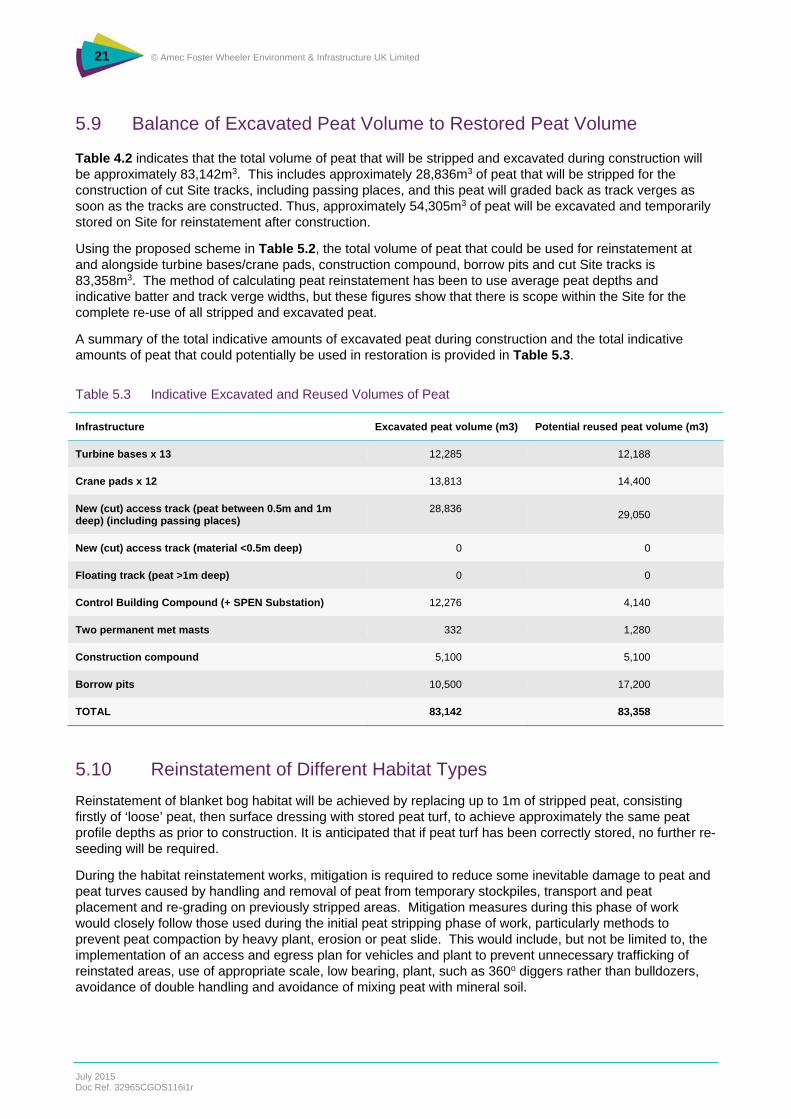
5.9 Balance of Excavated Peat Volume to Restored Peat Volume
Table 4.2 indicates that the total volume of peat that will be stripped and excavated during construction will be approximately 83,142m3. This includes approximately 28,836m3 of peat that will be stripped for the construction of cut Site tracks, including passing places, and this peat will graded back as track verges as soon as the tracks are constructed. Thus, approximately 54,305m3 of peat will be excavated and temporarily stored on Site for reinstatement after construction.
Using the proposed scheme in Table 5.2, the total volume of peat that could be used for reinstatement at and alongside turbine bases/crane pads, construction compound, borrow pits and cut Site tracks is 83,358m3. The method of calculating peat reinstatement has been to use average peat depths and indicative batter and track verge widths, but these figures show that there is scope within the Site for the complete re-use of all stripped and excavated peat.
A summary of the total indicative amounts of excavated peat during construction and the total indicative amounts of peat that could potentially be used in restoration is provided in Table 5.3.
Table 5.3 Indicative Excavated and Reused Volumes of Peat
Infrastructure Excavated peat volume (m3) Potential reused peat volume (m3)
Turbine bases x 13 12,285 12,188
Crane pads x 12 13,813 14,400
New (cut) access track (peat between 0.5m and 1m deep) (including passing places)
28,836 29,050
New (cut) access track (material <0.5m deep) 0 0
Floating track (peat >1m deep) 0 0
Control Building Compound (+ SPEN Substation) 12,276 4,140
Two permanent met masts 332 1,280
Construction compound 5,100 5,100
Borrow pits 10,500 17,200
TOTAL 83,142 83,358
5.10 Reinstatement of Different Habitat Types
Reinstatement of blanket bog habitat will be achieved by replacing up to 1m of stripped peat, consisting firstly of ‘loose’ peat, then surface dressing with stored peat turf, to achieve approximately the same peat profile depths as prior to construction. It is anticipated that if peat turf has been correctly stored, no further re-seeding will be required.
During the habitat reinstatement works, mitigation is required to reduce some inevitable damage to peat and peat turves caused by handling and removal of peat from temporary stockpiles, transport and peat placement and re-grading on previously stripped areas. Mitigation measures during this phase of work would closely follow those used during the initial peat stripping phase of work, particularly methods to prevent peat compaction by heavy plant, erosion or peat slide. This would include, but not be limited to, the implementation of an access and egress plan for vehicles and plant to prevent unnecessary trafficking of reinstated areas, use of appropriate scale, low bearing, plant, such as 360o diggers rather than bulldozers, avoidance of double handling and avoidance of mixing peat with mineral soil.

22 © Amec Foster Wheeler Environment & Infrastructure UK Limited
July 2015 Doc Ref. 32965CGOS116i1r
During reinstatement works, measures to manage and treat Site run-off, and prevent soil erosion during the works will also be set in place through a series of specific drainage control measures set out in Enoch Hill Wind Farm ES Chapter 13 - Geology, Hydrology and Hydrogeology.
5.11 Summary of Peat Handling and Replacement Methods
During peat reinstatement the following fundamental measures would be taken to preserve peat quality and to ensure the speediest re-establishment of appropriate vegetation:
Replace and spread out the stockpiled peat in the order: loose peat first and replaced peat turves second, either to the depth of peat recorded prior to construction, or to the pre-determined depth of peat prescribed in the PMP;
In all reinstatement activities, avoid compaction and any unnecessary damage to peat turves; and
Regularly water the replaced turves if reinstatement activities take place in dry summer conditions.
In order to ensure that the minimum amount of peat compaction occurs during placement when heavy machinery is being used, the contractor will develop a method for ‘loose’ tipping and spreading of loose peat in each compartment. Spreading and very light tamping down of placed peat is likely to be, for example, by use of the bucket on a long reach excavator.
Peat handling and placement during reinstatement activities should be carried out while the peat and weather is as dry as possible. Wherever practicable, these activities will be scheduled to take place during summer and early autumn conditions. Criteria for cessation of works are provided in Section 7.7.

23 © Amec Foster Wheeler Environment & Infrastructure UK Limited
July 2015 Doc Ref. 32965CGOS116i1r
6. Monitoring and Inspection
6.1 Introduction
Neither in situ monitoring of peat conditions, nor sampling and analysis of peat is prescribed. Water quality monitoring and regular inspections of restored vegetation conditions and runoff water conditions will be carried out throughout the construction and restoration phases of work. These will act as surrogates for peat monitoring – since both depend heavily on correct peat management, particularly correct temporary storage and restoration. Water quality monitoring is described in Enoch Hill Wind Farm ES Chapter 13 – Geology, Hydrology and Hydrogeology. Regular inspections of vegetation restoration conditions and runoff water quality conditions will be carried out by the ECoW as part of the routine Site inspections.
Regular, frequent inspections of peat conditions during construction and restoration phases of work will be carried out by the ECoW as follows:
Peat surface, peat profile and peat consistency conditions would be carried out as part of the peat depth survey prior to the start of construction. This information will provide the baseline conditions for each part of the infrastructure footprint and the basis of site-specific PSRAs for the temporary storage of excavated peat;
Temporary peat stockpiles and storage of peat turves will be inspected weekly according to the checklist in Appendix B. If any non-compliances are found, corrective actions will be invoked according to the process described in Section 6.2;
Restored peat conditions will be inspected immediately after restoration to ensure that the methods outlined in Sections 5.8 and 5.10 of this PMP have been correctly implemented and to inform any corrective actions should they be required;
Peat physical conditions must be retained as carefully as possible both at the peat storage and peat reinstatement stages. This is particularly important for vegetation establishment.
Visual inspection of stockpiles will follow the checklist in Appendix B of this PMP. Visual inspections of restored areas will record any locations where any of the following conditions occur after reinstatement, in order to formulate remedial actions:
Bare peat surfaces without peat turf which require stabilisation and re-seeding;
Any areas of eroding peat turf, for example where replacement of turf on a gradient has occurred and stabilisation is required; and/or
Any areas of ponded water where temporary or permanent adjustment/re-design of the surface water drainage system is required.
6.2 Failure to Meet Acceptability Criteria and Corrective Actions
Should there be any incidences where inspections of peat storage areas or reinstated peat areas identify any of the issues listed in Appendix B (storage areas) or in Section 5.10 (reinstated areas), corrective actions will be invoked. This procedure is particularly important at the storage/stockpiling stage to ensure that there is no risk of peatslide or peat erosion and in the final phase of works, once reinstatement activities are completed, to ensure that any non-compliances are corrected before re-vegetation activities take place.
6.3 Recording of Non-compliance and Corrective Actions
The identification, recording and reporting of non-compliances is important since this is the route whereby corrective actions are implemented. Should any non-compliances be identified, they will be reported via the PMP Auditing procedure (see Section 7).

24 © Amec Foster Wheeler Environment & Infrastructure UK Limited
July 2015 Doc Ref. 32965CGOS116i1r

25 © Amec Foster Wheeler Environment & Infrastructure UK Limited
July 2015 Doc Ref. 32965CGOS116i1r
7. Quality Control and Audit Procedure
7.1 PMP Audit Procedure as Part of the CEMP
This section of the PMP addresses the auditing process required to ensure that the correct checks and inspections are carried out, that non-compliances are identified, reported and rectified, with measures put in place to prevent future occurrences, and that the required inspections are carried out, correctly interpreted, reported and acted upon as required.
The auditing process for recording peat conditions in storage/stockpile areas will form part of the overall Proposed Development’s documentation procedure. The PMP auditing process will include documentation, incident reporting and a procedure for implementing corrective actions. It will also describe any required review procedures.
7.2 PMP Audit Procedure
A series of checklists and reports will be established which control and record PMP activities, particularly the results of peat inspections.
7.3 Peat Stripping and Stockpiling Documentation and Plans
The documentation and database to be used to log and chronicle the origin, handling, transport, storage/stockpiling, inspections and final peat reuse will be developed in detail by the Construction Contractor prior to the start of construction on Site.
The written procedure for peat stripping and storage/stockpiling will form part of the Construction Method Statement.
As construction activities proceed, the PMP will indicate locations and quality of in-situ peat and peaty soils: particularly the depth of peat, together with schedules of actual volumes of peat stripped and expected after-use. Documentation will identify the person(s) responsible for supervising and overseeing peat management during the works (see Section 8 of this PMP on Roles and Responsibilities). Drawings will also be produced to show all areas to be protected from peat stripping activities and locations of haul roads, compounds etc.
The practical implementation, administration and day to day auditing of the PMP would be provided as part of the CEMP and will be incorporated into the Construction Method Statement.
7.4 Scheduling of PMP Audit Activities and Reporting
The scheduling of PMP audit activities will be developed as part of the PMP and will be held in the CEMP.
7.5 Audit Checklist and Reporting
An audit checklist for the PMP is provided in Appendix C. This should be used to ensure that weekly inspections and checks are implemented and recorded in a timely manner and that monthly status reports are prepared on schedule.
7.6 Reporting of Non-compliances
Non-compliances will be reported as soon as they are identified by programmed inspections. They will be reported via the PMP Auditing procedure to the Construction Manager and corrective actions will be identified and implemented promptly. This will require timely decision making. If further inspections are required to ensure that acceptability criteria have been achieved, this will be prescribed and implemented. To

26 © Amec Foster Wheeler Environment & Infrastructure UK Limited
July 2015 Doc Ref. 32965CGOS116i1r
facilitate speedy rectification of any non-compliances, the Construction Contractor’s Site Environmental Engineer will be responsible for day to day decisions on routine non-compliance issues.
7.7 Criteria for Cessation of Works
Experience has shown that the combination of wet weather and wet peat conditions create very difficult conditions for vehicle and plant operations and elevate the possibility of peatslide and peat erosion, leading, for example, to impaired water quality impacts. For this reason, appropriate weather criteria are prescribed in this section to provide thresholds beyond which peat stripping, handling and stockpiling activities will cease.
If sustained heavy rainfall occurs during soil/peat stripping operations, work must be suspended and not restarted until the ground has at least one full dry day to recover. Rainfall quantities and soil/peat wetness conditions considered to be cut-off thresholds for cessation of soil/peat stripping/handling works will be agreed in advance of any works occurring on Site between the Construction Contractor and all stakeholders, including the relevant environmental regulators.
If sustained snowfall and freezing conditions occur, soil/peat stripping and/or stockpiling, and/or restoration activities will cease. When thawing conditions occur, the Construction Contractor’s Site Environmental Engineer will use forecast meteorological conditions to determine the appropriate timescale for restarting any peat management activities (stripping, handling, storage, restoration). The decision-making will pay due attention to the potential for rapid and turbulent snowmelt runoff, peat erosion and peatslide risk.
What constitutes ‘adverse weather and snow conditions’ which are the criteria for cessation of works will be agreed with relevant stakeholders by the Construction Contractor in advance of the start of any site construction works on Site.
7.8 Use of Tool Box Talks
Regular Tool Box talks will be used to ensure that all Site staff are aware of the PMP and applicable peat handling and protection procedures. The Tool Box Talks will be site-specific, discussing peat conditions at the Site.
An indicative list of possible toolbox talks is provided in Table 7.1 below:
Table 7.1 List of Example Tool Box Talks
Example Tool Box Talks
Why peat resources need to be protected. Site restrictions and good practice activities in order to protect peat resources.
Planning peat management. Access and egress routes.
Peat stripping. Why segregation of peat and mineral soil is important.
Peat reinstatement. Why and how.

27 © Amec Foster Wheeler Environment & Infrastructure UK Limited
July 2015 Doc Ref. 32965CGOS116i1r
8. Roles and Responsibilities
The implementation of the PMP will require certain key responsibilities to be assigned to defined roles. The PMP will be part of the CEMP and the hierarchy of roles and responsibilities illustrated in that document is also appropriate for the PMP. The roles described below are key to the success of the PMP.
Key roles in the effective delivery of the PMP lie with the Construction Contractor’s Site Environmental Engineer who will supervise and provide quality control on peat stripping, stockpiling and restoration aspects of work. The Site Environmental Engineer will also have ultimate responsibility to ensure that all peat management and monitoring obligations are met. The Site Environmental Engineer will have a key role in ensuring that the control measure methodologies described in this PMP are correctly implemented. The Site Environmental Engineer will be assisted by an ECoW for the Proposed Development. The ECoW will be responsible for carrying out in situ peat inspections of temporary storage/stockpiling areas and peat conditions in restored areas.
A Peat Specialist will be invoked for assessment of any technical peat issues, including siting of temporary peat storage areas and peat restoration methods.
Roles and responsibilities in relation to the PMP are summarised below in Table 8.1.
Table 8.1 Summary of PMP Roles and Responsibilities
Role Responsibility
Construction Contractor’s Site Environmental Engineer
Oversees the implementation of the PMP, checking that prescribed methodologies are being
correctly implemented;
Provides overall quality control on peat management;
Responsible for decision making on any day to day issues or routine non-compliances ;
Ensures that all peat management and monitoring obligations are met;
Ensures joined-up thinking and implementation between proposed mitigation, e.g. Enoch Hill
Wind Farm ES Chapter 11 - Ecology, and various management plans, as well as Enoch Hill
Wind Farm ES Chapter 13, and proposed SUDs and both construction and operational drainage
schemes.
ECoW Carries out regular inspection of peat stripping, checking that peat and mineral soil are not being
mixed, peat handling, methods of peat storage/stockpiling, conditions peat in temporary
storage/stockpiling areas and both peat restoration activities and peat restoration conditions; and
Reports any non-compliances to the Site Environmental Engineer.

28 © Amec Foster Wheeler Environment & Infrastructure UK Limited
July 2015 Doc Ref. 32965CGOS116i1r

29 © Amec Foster Wheeler Environment & Infrastructure UK Limited
July 2015 Doc Ref. 32965CGOS116i1r
References
Department of the Environment, Food and Rural Affairs (Defra) (2009) Code of Practice on Sustainable Soils on Construction Sites.
Ministry of Agriculture, Fisheries and Food (MAFF) (2000) Good Practice Guide for Handling Soils by Machine.
Scottish Renewables and SEPA (2012) Developments on Peatland: Guidance on the Assessment of Peat Volumes, Reuse of Excavated Peat and the Minimisation of Waste.
SNH, Scottish Environment Protection Agency (SEPA), Scottish Government and James Hutton Institute; Guidance on Developments on Peatlands: Site Surveys. http://www.gov.scot/Topics/Business-Industry/Energy/Energy-sources/19185/17852-1/CSavings/PSG2011

30 © Amec Foster Wheeler Environment & Infrastructure UK Limited
July 2015 Doc Ref. 32965CGOS116i1r

A1 © Amec Foster Wheeler Environment & Infrastructure UK Limited
July 2015 Doc Ref. 32965CGOS116i1r
Appendix A Soil Excavation Volumes for each Element of Infrastructure
This Appendix provides the raw data used to calculate peat excavation volumes for all elements of the Proposed Development’s infrastructure.
Table A.1 Peat Depths and Excavated Volumes at Each Turbine
Wind Turbines on peat <0.5m deep (not regarded as peat for the purposes of calculated peat volumes)
Wind Turbines on peat 0.5m and >0.5m deep
Turbine Number
Total area of turbines (m2)
Peat Depth (m)
Volume (m3)
Turbine Number
Total area of turbines (m2)
Peat Depth (m)
Volume (m3)
1 625 0.30 187.5 2 756 2.40 1,814
6 625 0.40 250 3 756 0.50 378
10 625 0.44 275 4 756 1.15 869
11 625 0.22 137.5 5 756 0.85 643
14 625 0.15 93.75 7 756 2.50 1,890
18 625 0.26 162.5 8 756 0.50 378
9 756 0.70 529
12 756 0.50 378
13 756 1.00 756
15 756 1.15 869
16 756 1.10 832
17 756 2.40 1,814
19 756 1.50 1,134
TOTAL (m3) 1,106.3 TOTAL (m3) 12,285
Average 0.30 Average 1.25

A2 © Amec Foster Wheeler Environment & Infrastructure UK Limited
July 2015 Doc Ref. 32965CGOS116i1r
Table A.2 Peat Depths and Excavated Volumes at Each Crane Pad
Crane Pads on peat <0.5m deep (not regarded as peat for the purposes of calculated peat volumes)
Crane Pads on peat >0.5m deep
Turbine Number
Total area of turbines (m2)
Peat Depth (m)
Volume (m3)
Turbine Number
Total area of turbines (m2)
Peat Depth (m)
Volume (m3)
1 1250 0.30 375 2 1250 1.30 1,625
4 1250 0.20 250 3 1250 0.60 750
10 1250 0.49 613 5 1250 0.60 750
11 1250 0.40 500 6 1250 0.50 625
12 1250 0.35 438 7 1250 1.00 1,250
16 1250 0.37 463 8 1250 0.75 938
18 1250 0.30 375 9 1250 0.80 1,000
13 1250 0.50 625
14 1250 0.50 625
15 1250 0.85 1,063
17 1250 2.30 2,875
19 1250 1.35 1,688
TOTAL (m3) 3,013 TOTAL (m3) 13,813
Average 0.34 Average 0.92
Table A.3 Peat Depths and Excavated Volumes for Construction Compound
Construction Compound
Compound Total Area (m2) Peat Depth (m) Volume (m3)
Primary 10,000 0.51 5,100
TOTAL (m3) 5,100
Table A.4 Peat Depths and Excavated Volumes for the Substation
Substation
Compound Total Area (m2) Peat Depth (m) Volume (m3)
1 19,800 0.62 12,276

A3 © Amec Foster Wheeler Environment & Infrastructure UK Limited
July 2015 Doc Ref. 32965CGOS116i1r
Table A.5 Peat Depths and Excavated Volumes at Permanent Met Masts
Permanent met masts
Mast Total Areas m2 Peat Depth m Volume m3
1 425 0.78 332
2 425 0.18 77 (not peat)
TOTAL (m3) 332
Table A.6 Peat Depths and Excavated Volumes at Borrow Pits
Borrow Pit Search Areas
Number Total Area m2 Peat depth m Volume m3
A 30,000 0.33 9,900 (not peat)
B 10,000 0.34 3,400 (not peat)
C 10,000 1.05 10,500
TOTAL 10,500
Peat Depths and Excavated Volumes on New and Upgraded Access Tracks
The total length of proposed new 6m wide access track amounts to 12.9km (12,900m). Peat will be excavated from approximately 50% of this length as follows:
123 points were probed along 6,150m of proposed new excavated road (6m wide) where the peat depth is between 0.5m and 1m, with an average depth of 0.71m. Passing places along these excavated roads extend to an area of 3,750m with an average peat depth of 0.68m. In total, this equates to 28,836m3 of peat;
Peat probes were taken at 38 points along sections extending over 1,900m where the peat depth is >1m (varying between 1m and 2.3m). Since it is proposed to use floating roads where peat depth >1m the volume of peat to be excavated along these sections amounts to Nil;
Peat probes were taken at 97 points along sections extending over 4,850m where the peat depth is <0.5m. Since peat that is <0.5m deep is not classified as peat for the purposes of this PMP, the volume of peat to be excavated along these sections amounts to Nil.

A4 © Amec Foster Wheeler Environment & Infrastructure UK Limited
July 2015 Doc Ref. 32965CGOS116i1r

B1 © AMEC Environment & Infrastructure UK Limited
July 2015 Doc Ref. 32965CGOS116i1r
Appendix B Soil Stockpile Inspection Checklist
All peat storage areas and stockpiles will be inspected weekly throughout the construction works to confirm appropriate conditions are being maintained.
The inspection checklist will include but may not be limited to the following:
Table B.1 Soil Stockpile Inspection Checklist
No Criteria To Check
1 Any locations where stockpiles have been constructed to higher than the threshold 2m elevation.
2 Any locations where boundaries between segregated peat and mineral soil stockpiles have become amalgamated, causing contamination of peat with mineral soil.
3 Any signs of surface peat erosion – caused by surface water runoff or wind, or any locations of surface water ponding, indicating that stockpile is not shedding water correctly.
4 Any signs of inappropriate vehicle tracking, indicating inappropriate access and trafficking, causing additional unnecessary compaction.

B2 © AMEC Environment & Infrastructure UK Limited
July 2015 Doc Ref. 32965CGOS116i1r

C1 © AMEC Environment & Infrastructure UK Limited
July 2015 Doc Ref. 32965CGOS116i1r
Appendix C Indicative Audit Checklist for the Peat Management Plan
Table C.1 Indicative Checklist for the Peat Management Plan
Element Indicative Checklist
Access Plan/Trafficking Inspect to ensure that the Access Plan is being adhered to and that there is no trafficking, stopping
of vehicles or refuelling of vehicles or plant outside of permitted areas marked on the Access Plan;
Inspect to ensure that there is no laydown of any materials outside of permitted areas on the Access
Plan;
Ensure that no plant traffics across any area of virgin peat and issue non-compliances where this
occurs;
Advise on restoration of any trafficked and/or damaged area.
Peat Stripping Method Ensure that correct peat turf depth is being adhered to when stripped – to ensure that peat structure
and strength is maintained;
Ensure that correct methods for excavation and transport of ‘loose’ peat are being adhered to.
Peat Storage/Stockpiling Inspect peat turf storage areas for each element of infrastructure and ensure that correct storage is
being adhered to;
Advise on whether watering of turves is required;
Inspect storage of ‘loose’ peat and carry out checklist in Appendix B;
Advise on any corrective actions on storage/stockpiles.
Peat Restoration Inspect replacement of ‘loose’ peat and peat turves and advise on any necessary corrective actions
(e.g. methods for prevention of erosion);
Advise on whether watering of turves after replacement is required.

C2 © AMEC Environment & Infrastructure UK Limited
July 2015 Doc Ref. 32965CGOS116i1r