Embed Size (px)
Citation preview

Appendix C: Hydraulic Design

Port of Nome Modification Feasibility Study Appendix C - Hydraulic Design Nome, Alaska
March 2020

C-i
TABLE OF CONTENTS 1.0 INTRODUCTION ........................................................................................................... 1
1.1 Appendix Purpose................................................................................................... 1
1.2 Project Purpose and Need ..................................................................................... 1
2.0 Port of Nome.................................................................................................................. 1
2.1 Existing Facilities..................................................................................................... 1
2.1.1 Causeway ......................................................................................................... 3
2.1.2 Seawall ............................................................................................................. 4
2.1.3 Main and Spur Breakwaters ............................................................................ 5
2.1.4 Entrance Channel and Turning Basin ............................................................. 6
2.1.5 Small Boat Harbor............................................................................................ 6
2.1.6 Harbor Bulkheads ............................................................................................ 6
2.2 Climatology .............................................................................................................. 7
2.3 Winds ....................................................................................................................... 7
2.4 Water Levels, Currents, and Waves ...................................................................... 9
2.4.1 Tides ................................................................................................................. 9
2.4.2 Sea Level Change.......................................................................................... 10
2.4.1 Storm Surge ................................................................................................... 16
2.4.2 Set-Down ........................................................................................................ 17
2.4.3 Currents .......................................................................................................... 17
2.4.4 Wave Climate ................................................................................................. 18
2.5 Hydrology .............................................................................................................. 21
2.6 Ice Conditions........................................................................................................ 22
2.7 Sedimentation ....................................................................................................... 23
3.0 DESIGN CRITERIA..................................................................................................... 24
3.1 Design Vessel and Fleet....................................................................................... 24
3.1.1 Bulk Fuel Delivery .......................................................................................... 24
3.1.2 Freight Delivery .............................................................................................. 25
3.1.3 Resource Extraction....................................................................................... 25
3.1.4 Search and Rescue ....................................................................................... 25

C-ii
3.1.5 Arctic Research .............................................................................................. 25
3.2 Allowable Wave Heights ....................................................................................... 25
3.3 Channel and Basin Widths and Depths ............................................................... 27
3.4 Circulation.............................................................................................................. 31
3.5 Ice Forces .............................................................................................................. 32
3.6 Life-Cycle Causeway Extension/Breakwater Design .......................................... 33
3.6.1 Port of Nome Life-Cycle Design .................................................................... 33
3.7 Dredging ................................................................................................................ 33
4.0 MODEL STUDIES ....................................................................................................... 34
4.1 Physical Modeling ................................................................................................. 34
4.2 Numerical Modeling .............................................................................................. 35
4.2.1 Navigation Simulation .................................................................................... 35
5.0 ALTERNATIVES ......................................................................................................... 39
5.1 Port of Nome Expansion....................................................................................... 39
5.1.1 Alternative 1.................................................................................................... 40
5.1.2 Alternative 2A ................................................................................................. 40
5.1.3 Alternative 2B ................................................................................................. 41
5.1.4 Alternative 3A ................................................................................................. 41
5.1.5 Alternative 3B ................................................................................................. 41
5.1.6 Alternative 3C ................................................................................................. 41
5.1.7 Alternative 4A ................................................................................................. 41
5.1.8 Alternative 4B ................................................................................................. 42
5.1.9 Alternative 5.................................................................................................... 42
5.1.10 Alternative 6.................................................................................................... 42
5.1.11 Alternative 7A ................................................................................................. 42
5.1.12 Alternative 7B ................................................................................................. 42
5.1.13 Alternative 8A ................................................................................................. 43
5.1.14 Alternative 8B ................................................................................................. 43
5.2 Wave Heights ........................................................................................................ 43
5.3 Circulation.............................................................................................................. 43
5.4 Shoaling ................................................................................................................. 44

C-iii
5.5 Construction Dredging .......................................................................................... 44
5.6 Dredged Material Disposal ................................................................................... 45
5.7 Maintenance Dredging.......................................................................................... 45
5.8 Causeway and Main Breakwater Extension Design ........................................... 46
5.9 Concrete Caisson Dock Design ........................................................................... 47
5.10 Steel Sheet Pile Modified Diaphragm Dock Design ............................................ 48
5.11 Uplands.................................................................................................................. 48
5.12 Entrance Channel Navigation............................................................................... 49
6.0 PROJECT IMPLEMENTATION.................................................................................. 49
6.1 Breakwaters and Causeways ............................................................................... 49
6.2 Dredging ................................................................................................................ 49
6.3 Modified Diaphragm Sheet Pile Dock .................................................................. 50
6.4 Caisson Dock ........................................................................................................ 50
6.5 Local Service Facilities ......................................................................................... 51
6.6 Aids to Navigation ................................................................................................. 51
6.7 Construction Schedule.......................................................................................... 52
7.0 OPERATIONS AND MAINTENANCE........................................................................ 53
8.0 RECOMMENDED FURTHER DESIGN STUDIES.................................................... 54
9.0 REFERENCES ............................................................................................................ 55
10.0 ATTACHMENTS ......................................................................................................... 57
LIST OF TABLES Table 1: PAOM Wind Speed Exceedance Probability ........................................................ 9 Table 2: Published tidal data for Nome, Alaska ................................................................ 10 Table 3: Sea Level Change Prediction for a 50-Year Period of Analysis ........................ 13 Table 4: Sea Level Change Prediction for the 100-Year Adaptation ............................... 13 Table 5: Maintenance Dredging Quantities since 2007 Harbor Expansion..................... 24 Table 6: Channel depth accessibility for the Port of Nome .............................................. 28 Table 7: Deep water -30 foot MLLW Channel Depth........................................................ 29 Table 8: Deep Water -35 foot MLLW Channel Depth ....................................................... 29 Table 9: Deep Water -40 foot MLLW Channel Depth ....................................................... 29 Table 10: Outer -25 foot MLLW Channel Depth ............................................................... 30
C-iv
Table 11: Outer -28 foot MLLW Channel depth ................................................................ 30 Table 12: Indicator aspect ratios for circulation analysis .................................................. 31 Table 13: Construction dredging quantities....................................................................... 45
LIST OF FIGURES (EMBEDDED) Figure 1: Port of Nome Federal Projects from Project Maps and Index Sheets, 2016..... 3 Figure 2: Nome Seawall Typical Section. This section is typical of the 1951 construction. The 2005 construction near the breakwater has side slopes of 1.5H:1V. ......................... 5 Figure 3: Spur and Main Breakwater Head Typical Section. ............................................. 5 Figure 4: Windrose for the Nome Airport............................................................................ 8 Figure 5: Wind Speed Exceedance Probability Chart for the Nome Airport..................... 9 Figure 6: NOAA Sea Level Trend for Station 9468756 Nome, Alaska. The relative seal level trend is 3.12 millimeters/year with a 95% confidence interval of +/- 2.92 mm/yr based on monthly mean sea level data from 1992 to 2018 which is equivalent to a change of 1.02 feet in 100 years........................................................................................ 12 Figure 7: Scenarios for SLC (based on updates to NRC 1987 equation) ....................... 13 Figure 8: Adaptation Horizon ............................................................................................. 16 Figure 9: Location of WIS station 82100 ........................................................................... 20 Figure 10: Analysis figure for WIS station 82100 (Jensen, 2014).................................... 21 Figure 11: Frequency of water levels at Nome, Alaska based on recorded water levels at Nome from 1992 to 2018 between April and November of each year. ....................... 28
LIST OF FIGURES (ATTACHMENTS) Figure 11: Location and Vicinity Map ………………………………………...………….…57 Figure 12: Alternative 2A ………………………………………....……..……….…………58 Figure 13: Alternative 2B ………………………………………………….……………..…59 Figure 14: Alternative 3A ……………………………………...……………………………60 Figure 15: Alternative 3B ………………………………………...…………………………61 Figure 16: Alternative 3C …………………………………………………………….……..62 Figure 17: Alternative 4A ……………………………………………………...……………63 Figure 18: Alternative 4B ………………………………………………….……………..…64 Figure 19: Alternative 5 ……………………………….…………………..…………………65 Figure 20: Alternative 6 ………………………………………………………………………66 Figure 21: Alternative 7A ……………………………………..……………..………………67 Figure 22: Alternative 7B ……………………………………………………………………68 Figure 23: Alternative 8A ………………………………..………………..…………………69 Figure 24: Alternative 8B …………..…………………………………..……………………70 Figure 25: West Causeway Cross Sections ….…………………………………………….71 Figure 26: Causeway Sections …………………………..…………...……………………72

C-v
Figure 27: Dredge Material Placement Areas ………………...……………………….…73 Figure 28: Alternative 8B Southwest Wave Diffraction …………………….…….………74 Figure 29: Alternative 8B Southeast Wave Diffraction ………….…….………….…..…75

Port of Nome Modification Feasibility Study March 2020 Appendix C - Hydraulic Design
C-1
1.0 INTRODUCTION 1.1 Appendix Purpose This appendix describes the technical aspects of proposed navigation improvements to the Port of Nome, Alaska. It provides the engineering background information for determining the Federal interest in the major construction features including causeways, breakwaters, channel improvements, and support facilities. Existing data was gathered and analyzed to determine site characteristics and numerical modeling was performed to determine the physical impacts of the wave climate and ice conditions for design of the proposed navigation improvements.
1.2 Project Purpose and Need The purpose of this Study is to identify a feasible solution that provides safe, reliable, and efficient navigation and mooring for vessels serving the hub community of Nome, Alaska. The project is needed to alleviate existing vessel restrictions that are imposed by insufficient channel depths and harbor area. Ship transportation in to the Port of Nome is presently limited by depth, with existing depths inadequate to safely accommodate vessels with drafts exceeding -22 ft MLLW.
2.0 PORT OF NOME The Port of Nome is the regional hub for maritime commerce. The port includes a federally maintained navigation channel and turning basin protected by rubble mound causeway and breakwater. Existing facilities at the port accommodate medium draft vessels with maximum moorage depths of -22 feet mean lower low water (MLLW).
2.1 Existing Facilities The Nome Federal navigation project was first authorized by the Rivers and Harbor Act of August 8, 1917. The authorization was to construct jetties, dredge a channel, and armor the banks of the Snake River with a stone revetment. Subsequent construction included modification of the original jetties, construction of a seawall along the Nome shoreline, construction of a rubble mound causeway into Norton Sound, construction of sheet pile docks on the causeway, construction of a breakwater adjacent to the causeway, and re-alignment of the Snake River (Figure 1). Construction of Port of Nome and related facilities progressed as follows:
1923 - The original 335 and 460-foot timber and concrete jetties and the revetments are completed.
1940 - The jetties are reconstructed with steel reinforced concrete to modified lengths of 240 and 400 feet.

Port of Nome Modification Feasibility Study March 2020 Appendix C - Hydraulic Design
C-2
1949 - Work begins on the seawall and the 400-foot extension to the turning basin. Records indicate annual maintenance dredging.
1951 - Construction of the seawall is completed in June. Extension of the turning basin to 600 feet in length is effectively completed.
1954 - The timber revetment is re-faced with sheet steel piling.
1964 - Contract is awarded for the repair of both jetties in July.
1965 - Repair to the jetties is completed in October.
1982 - The east jetty incurs damage in the spring of 1982; the last 40 feet is detached from the remainder of the structure.
1985 - Construction of 700 linear feet of the Nome Causeway is completed.
1986 - Interim repairs are completed on the sheet pile wall in the entrance channel; Nome Causeway construction completed to 2,700 linear feet.
1989 - 190’ long West Gold sheet pile dock constructed on the Nome Causeway.
1991 - 200’ long City Dock sheet pile dock constructed on the Nome Causeway.
2004 - Construction begins on the new breakwaters and entrance channel.
2005 - The original entrance channel is dredged for the last time in June and closed off in July after construction of the new entrance channel. Construction on the new breakwater and causeway spur continues.
2006 - The new entrance channel is dredged. The breach through the sand spit is armored to prevent sloughing of material into the channel. New steel sheet pile is installed on the south side of the inner harbor.
2007 - Construction of the sheet pile replacement on the south side of the inner harbor is completed.
2008 - Construction of the sheet pile replacement on the Crowley (east) dock is completed.
2011 - A November storm caused minor damage to the north bridge abutment fill with repairs scheduled for the following summer.
2012 - Temporary repairs are made to the bridge abutments in May by the City of Nome. USACE Comprehensive Evaluation of Project Datums (CEPD) Compliance report completed and recorded in August.
2013 - 200’ long Middle Dock sheet pile dock constructed on the Nome Causeway. The causeway bridge is grouted between the sheet pile wall and the cap beam.

Port of Nome Modification Feasibility Study March 2020 Appendix C - Hydraulic Design
C-3
2014 - The south sheet pile wall factor of safety is increased by removing material in a 25-foot-wide width by 2-feet deep area along the AZ34/AZ18 section of the wall. About 630 cubic yards of soil is removed.
2015 - An inspection of the causeway bridge is performed in mid-April from the sea ice and followed up by an underwater inspection in August. Only minor deficiencies are noted. A LRFR load rating is also completed for the causeway bridge.
Figure 1: Port of Nome Federal Projects from Project Maps and Index Sheets, 2016.
2.1.1 Causeway The causeway was designed by Tippetts, Abbett, McCarthy, Stratton (TAMS) Engineers to replace the historic open-water lightering system used for resupply of Nome and outlying villages. The City of Nome began construction of the causeway in November 1985. Construction history and other information is contained in the "1989 Annual Report of Nome Littoral Drift Monitoring and Shore Protection Program," prepared by the city of Nome. This report chronicles the construction sequence as follows.
In November 1985, 700 linear feet of the causeway was constructed. Causeway construction was shut down for the winter season on November 21, 1985. In June 1986, construction of the causeway resumed, with work proceeding until November 1, 1986, when the causeway reached its current length of 2,700+ linear feet. Final armor stones were placed in June 1987.

Port of Nome Modification Feasibility Study March 2020 Appendix C - Hydraulic Design
C-4
The causeway was constructed with 22-ton, 16-ton, and 8-ton armor rock on the west side of the trunk, 22-ton rock at the head, and 8-ton rock on the east side of the trunk. The side slope of the west side and head is 2H:1V; the side slope on the east is 1.5H:1V. The top elevation of the west face varies from +20 to +28 feet MLLW. The east face top elevation is +15 feet MLLW. The core of the causeway is pit run tailings, which is clean gravel with a maximum unit weight of 100 pounds and not more than 5 percent by weight passing a 200 sieve. Adequate mass was placed to resist up to 110 kips per linear foot of lateral ice thrust.
A breach was left in the causeway for passing fish and other marine life. The breach was established at the -7-foot MLLW depth contour and bridged to allow cargo transfer. This bridge was replaced in 2005 when the main breakwater was constructed with a steel girder bridge supported by Open Cell™ abutments. The bridge has a two-axle load capacity of 120 tons and a three axle load capacity of 130 tons. Heavier loads require a special overload permit from the Alaska District.
After completion of the causeway, two earth-filled circular sheet pile docks were constructed on its east side. The inner or northernmost cell, West Gold Dock, was completed in the fall of 1989. The outer cell, City Dock, was completed in August 1991. Both docks were designed by a consultant and are owned and operated by the City of Nome. The outer dock is used by the large petroleum barges and has the pipeline and headers for this type of cargo transfer.
The causeway structure is in excellent condition. There has been no known movement of armor stone due to wave and ice forces since its initial construction. Cargo handling is curtailed to some degree because the bridge across the fish passage breach controls loads on the causeway road.
2.1.2 Seawall The original project was constructed during the years 1947 through 1951. The revetment protects the town from damage during the severe coastal storm events that frequently occur in Norton Sound. The total length of the federally constructed, locally maintained portion of the project is 3,350 linear feet beginning just east of Campbell Avenue at the east end and proceeding westerly. As part of a Federal navigation project, a 460-foot extension on the west end was constructed in 2005. The City of Nome is not responsible for O&M on the 460-foot extension of the rock revetment. The Federal portion of the project crosses where the old harbor entrance channel was located and ends approximately aligned with West D Street. The original project consists of a rock revetment with a single layer of armor stone on a 2H:1V side slope and a 15-foot-wide toe apron (Figure 2). The crest elevation of the revetment is +18 feet MLLW. The seawall extension consists of a rock revetment with 8 to 10-ton armor stone on a 1.5H:1V side slope and a 15-foot-wide toe. Its crest elevation is also +18 feet

Port of Nome Modification Feasibility Study March 2020 Appendix C - Hydraulic Design
C-5
MLLW. Armor stone weights for the original project are assumed to range from 12,000 to 20,000 pounds with some percentage larger stones. Armor stone specified for the 460-foot extension have a median weight of 16,000 pounds and range from 12,000 to 20,000 pounds.
Figure 2: Nome Seawall Typical Section. This section is typical of the 1951 construction. The 2005 construction near the breakwater has side slopes of 1.5H:1V.
2.1.3 Main and Spur Breakwaters A U.S. Army Corps of Engineers (USACE) Navigation Improvements project was designed in 1998. The design consisted of a new main breakwater to the east of the causeway, a new spur breakwater extension of the causeway head, and a new dredged entrance channel into the harbor between the main breakwater and spur breakwater/causeway. The spur and main breakwaters were constructed in 2005. The outer layers of the spur and main breakwaters consist of 22-ton, 16-ton and 8-ton armor stone, with the heaviest stone placed at the head of the breakwater and lighter stones placed shoreward. The crest elevation is + 14 feet MLLW; the crest is 20 feet wide and the armor stone was placed on a 2H:1V slope. The main and spur breakwaters are owned by the City of Nome; however, O&M responsibility remains Federal. Figure 3 shows the typical section for the spur and main breakwater heads.
Figure 3: Spur and Main Breakwater Head Typical Section.
Port of Nome Modification Feasibility Study March 2020 Appendix C - Hydraulic Design
C-6
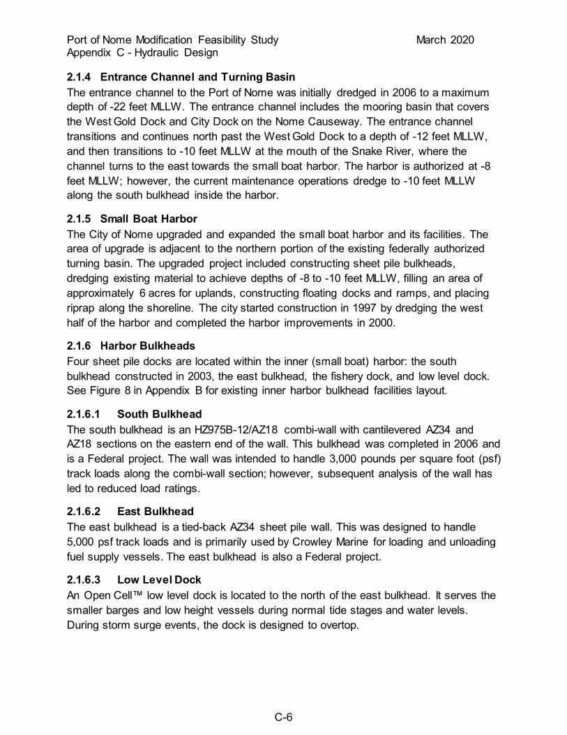
2.1.4 Entrance Channel and Turning Basin The entrance channel to the Port of Nome was initially dredged in 2006 to a maximum depth of -22 feet MLLW. The entrance channel includes the mooring basin that covers the West Gold Dock and City Dock on the Nome Causeway. The entrance channel transitions and continues north past the West Gold Dock to a depth of -12 feet MLLW, and then transitions to -10 feet MLLW at the mouth of the Snake River, where the channel turns to the east towards the small boat harbor. The harbor is authorized at -8 feet MLLW; however, the current maintenance operations dredge to -10 feet MLLW along the south bulkhead inside the harbor.
2.1.5 Small Boat Harbor The City of Nome upgraded and expanded the small boat harbor and its facilities. The area of upgrade is adjacent to the northern portion of the existing federally authorized turning basin. The upgraded project included constructing sheet pile bulkheads, dredging existing material to achieve depths of -8 to -10 feet MLLW, filling an area of approximately 6 acres for uplands, constructing floating docks and ramps, and placing riprap along the shoreline. The city started construction in 1997 by dredging the west half of the harbor and completed the harbor improvements in 2000.
2.1.6 Harbor Bulkheads Four sheet pile docks are located within the inner (small boat) harbor: the south bulkhead constructed in 2003, the east bulkhead, the fishery dock, and low level dock. See Figure 8 in Appendix B for existing inner harbor bulkhead facilities layout.
2.1.6.1 South Bulkhead The south bulkhead is an HZ975B-12/AZ18 combi-wall with cantilevered AZ34 and AZ18 sections on the eastern end of the wall. This bulkhead was completed in 2006 and is a Federal project. The wall was intended to handle 3,000 pounds per square foot (psf) track loads along the combi-wall section; however, subsequent analysis of the wall has led to reduced load ratings.
2.1.6.2 East Bulkhead The east bulkhead is a tied-back AZ34 sheet pile wall. This was designed to handle 5,000 psf track loads and is primarily used by Crowley Marine for loading and unloading fuel supply vessels. The east bulkhead is also a Federal project.
2.1.6.3 Low Level Dock An Open Cell™ low level dock is located to the north of the east bulkhead. It serves the smaller barges and low height vessels during normal tide stages and water levels. During storm surge events, the dock is designed to overtop.

Port of Nome Modification Feasibility Study March 2020 Appendix C - Hydraulic Design
C-7
2.1.6.4 Fishery Dock The fishery dock is located on the western edge of the harbor across from the east bulkhead. This dock is also an Open Cell™ structure, and it serves the commercial fishing and crab fleet for offloading of product.
2.2 Climatology The City of Nome is located along the northern coast of Norton Sound, approximately 545 miles by air northwest of Anchorage. The climate is influenced by both the Norton Sound and Bering Sea maritime conditions. Norton Sound typically has open water from early June to about the middle of November. Storms within the region during the summer and fall months result in extended periods of cloudiness and rain. Average daily summer temperature variation is slight due to maritime influence. July temperatures are typically in the range of 46 to 58 degrees F. Following freeze-up in November, an abrupt change from a maritime to a continental climate is prevalent. Temperatures generally remain well below freezing from the middle of November to the latter part of April with January typically the coldest month of the year. January temperatures range from -3 to 13 degrees F (U.S. Climate Data 2019). Average annual precipitation is 16.48 inches, with 77 inches of snowfall (U.S. Climate Data 2019). Precipitation reaches its maximum in late summer and drops to a minimum in April and May
According to the Fourth National Climate Assessment (2017, Vol. 1), a warming trend relative to average air temperatures recorded from 1925 through 1960. A trend of increasing temperatures starting in the 1970s has been identified and is projected to continue throughout the state of Alaska. The largest temperature increases have been found in winter months with average minimum temperature increases of around 2 degrees Fahrenheit statewide. Annual maximum one-day precipitation is projected to increase by 5%–10% in southeastern Alaska and by more than 15% in the rest of the state, although the longest dry and wet spells are not expected to change over most of the state.
An increase in the average temperature in the region may increase the potential for permafrost melting in the region. Thawing permafrost is not an issue for this particular project location.
2.3 Winds Nome Airport hosts a weather station which has been operational since 1970. The predominant wind directions are from the north and east for the entire year (Figure 4). Calm conditions, wind speeds 0-2 mi/hr, are present 11 percent of the time ( Figure 5, Table 1). The average wind speed is 8.6 knots. Wind speeds exceeding 15 knots are predominantly from the west, southwest and south directions during the summer

Port of Nome Modification Feasibility Study March 2020 Appendix C - Hydraulic Design
C-8
months. Wind speeds exceeding 15 knots are predominantly from the east and northeast directions during the fall, winter, and spring months.
Figure 4: Windrose for the Nome Airport

Port of Nome Modification Feasibility Study March 2020 Appendix C - Hydraulic Design
C-9
Figure 5: Wind Speed Exceedance Probability Chart for the Nome Airport
Table 1: PAOM Wind Speed Exceedance Probability (May through October)
Wind Speed Exceedance (knots) (percent)
5 79.9% 10 36.3% 15 11.3% 20 2.6% 25 0.4% 30 0.07%
Source: Iowa Environmental Mesonet May 1970-16 Oct 2019.
2.4 Water Levels, Currents, and Waves
2.4.1 Tides The tidal influence at Nome is relatively small, and the tides are primarily diurnal. Much larger water surface elevation fluctuations occur at Nome due to storm surges than shown in Table 2. Tidal data, referenced to MLLW, are shown in Table 2.

Port of Nome Modification Feasibility Study March 2020 Appendix C - Hydraulic Design
C-10
Table 2: Published tidal data for Nome, Alaska
Published tidal data for Nome, Alaska (ft)
Highest Observed Water Level (10/19/04)… +9.83 Mean Higher High Water (MHHW) ............. +1.52 Mean High Water (MHW).............................. +1.33 Mean Sea Level (MSL)…………………… +0.82 Mean Tide Level (MTL)…………………. +0.81 Mean Low Water (MLW).............................. +0.30 Mean Lower Low Water (MLLW).................. 0.00 (datum) Lowest Observed Water Level (11/11/05)...... -6.69
Source: NOAA NOS, Tidal Epoch 1983-2001, published 10/06/11.
Given the data in Table 2, the mean tide level (arithmetic average of the Mean High Water and the Mean Low Water) is 0.82 foot and the mean tide range (the difference between Mean High Water and Mean Low Water) is 1.03 feet.
2.4.2 Sea Level Change USACE requires that planning studies and engineering designs consider alternatives that are formulated and evaluated for the entire range of possible future rates of sea level change (SLC). Guidance for addressing SLC is in Engineer Regulation ER 1100-2-8162 and detailed below. Three scenarios of “low,” “intermediate,” and “high” SLC are evaluated over the project life cycle. According to the EC, the SLC “low” rate is the historic SLC. The “intermediate” and “high” rates are computed using:
• Estimate the “intermediate” rate of local mean sea-level change using the modified NRC Curve I and the NRC equations. Add those to the local historic rate of vertical land movement.
• Estimate the “high” rate of local mean SLC using the modified NRC Curve III and NRC equations. Add those to the local rate of vertical land movement. This “high” rate exceeds the upper bounds of Intergovernmental Panel on Climate Change (IPCC) estimates from both 2001 and 2007 to accommodate potential rapid loss of ice from Antarctica and Greenland.
NRC Equations
The 1987 NRC described these three scenarios using the following equation in which t represents years, starting in 1986, b is a constant, and E(t) is the eustatic sea level change, in meters, as a function of t.:
E(t) = 0.0012t + bt2

Port of Nome Modification Feasibility Study March 2020 Appendix C - Hydraulic Design
C-11
The NRC committee recommended “projections be updated approximately every decade to incorporate additional data.” At the time the NRC report was prepared, the estimate of global mean sea level change was approximately 1.2 mm/year. Using the current estimate of 1.7 mm/year for GMSL change, as presented by the IPCC (IPCC 2007), results in this equation being modified to be:
E(t) = 0.0017t + bt2
The three scenarios proposed by the NRC result in global eustatic sea level rise values, by the year 2100, of 0.5 meter, 1.0 meter, and 1.5 meters. Adjusting the equation to include the historic GMSL change rate of 1.7 mm/year and the start date of 1992 (which corresponds to the midpoint of the current National Tidal Datum Epoch of 1983-2001), results in updated values for the variable b being equal to 2.71E-5 for modified NRC Curve I, 7.00E-5 for modified NRC Curve II, and 1.13E-4 for modified NRC Curve III. The three GMSL rise scenarios are shown in Figure 7.
Manipulating the equation to account for the fact that it was developed for eustatic sea level rise starting in 1992, while projects will actually be constructed at some date after 1992, results in the following equation:
E(t2) – E(t1) = 0.0017(t2 – t1) + b(t22 – t12)
where t1 is the time between the project’s construction date and 1992 and t2 is the time between a future date at which one wants an estimate for sea level change and 1992 (or t2 = t1 + number of years after construction) . For the three scenarios proposed by the NRC, b is equal to 2.71E-5 for Curve 1, 7.00E-5 for Curve 2, and 1.13E-4 for Curve 3.
The Nome tide station does not have the recommended 40-year period of record for the relative sea level change (RSLC) value. The Nome tide station has a 26-year period of record with 22 years of data. Based on NOAA Relative Sea Level Trend data, the RSLC is +3.12mm/yr ±02.92 mm/yr. Per the guidance recommendation, a U.S. tide station with a 40-year period of record was investigated for use as the RSCL value. The nearest U.S. tide station with the required 40-year period of record is the Anchorage, Alaska station, roughly 540 miles from the site. It has a historic relative sea level change (RSLC) of -0.62 mm/yr. Due to the distance from Nome and the differences between SLC rates the Anchorage station was not considered within the same SLC region as Nome and the Anchorage gage was not further investigated. To model sea level change at Nome, three scenarios were identified; the GMSL rate, and the GMSL rate including vertical land movement (VLM) was compared to the data available from Nome (Table 3). According to the NASA Jet Propulsion Laboratory, 2019, the local rate of VLM for Nome is -0.477 mm/yr ±0.368 mm/yr. Per instruction from the Climate Preparedness and Resilience CoP Lead the Vertical Land Movement used in SLC calculation was changed to 0 mm/yr. While the Nome station does not have the recommended 40 year period of record, it more accurately accounts for vertical land

Port of Nome Modification Feasibility Study March 2020 Appendix C - Hydraulic Design
C-12
movement effects in the region which are not represented by GMSL change. To best model sea level change at Nome, the Nome station data was used. The sea level change prediction used in the formulation of all alternatives was the intermediate curve.
Figure 6: NOAA Sea Level Trend for Station 9468756 Nome, Alaska. The relative seal level trend is 3.12 millimeters/year with a 95% confidence interval of +/- 2.92 mm/yr based on monthly mean sea level data from 1992 to 2018 which is equivalent to a change of 1.02 feet in 100 years.

Port of Nome Modification Feasibility Study March 2020 Appendix C - Hydraulic Design
C-13
Figure 7: Scenarios for SLC (based on updates to NRC 1987 equation)
Table 3: Sea Level Change Prediction for a 50-Year Period of Analysis (2023-2073)
Scenario Low (Historic) Intermediate (Curve I) High (Curve III)
GSLC +0.28 feet +0.78 feet +2.35 feet
GSLC+VLM +0.28 feet +0.78 feet +2.35 feet
Nome +0.51 feet +1.01 feet +2.59 feet
Table 4: Sea Level Change Prediction for the 100-Year Adaptation Horizon (2023-2123)
The intermediate RSLC estimates that 1.0 feet of sea level rise could occur at the end of the 50-yr period of analysis and that 2.5 feet of sea level rise could occur at the end of the 100-yr adaptation horizon. In response to the use of the intermediate RSLC the
Scenario Low (Historic) Intermediate (Curve I) High (Curve III) GSLC +0.56 feet +2.00 feet +6.56 feet
GSLC+VLM +0.56 feet +2.00 feet +6.56 feet Nome +1.02 feet +2.46 feet +7.03 feet

Port of Nome Modification Feasibility Study March 2020 Appendix C - Hydraulic Design
C-14
crest height of the wave protection features was increased by half a foot and a single row of A1 armor (22 ton) capstone was placed on the crest of the causeways. This modification increases the height of armor stone protection 8 feet above that present in the existing causeway. This height of armor protection is expected to significantly limit the amount of overtopping seen on the causeways from the 50-yr wave event during both the 50-yr period of analysis and the 100-yr adaptation horizon.
Increased water levels due to sea level rise is not anticipated to have any effect on the stability if the causeway armor protection. Increasing water levels will affect the capstone armor stability through higher wave loading from over-topping. It is estimated that the capstone armor may lose stability and slide as the height of wave over-topping exceeds 3.75 feet (4.25 feet RSLC). This height of wave over-topping is not expected for intermediate RSLC scenario during either the 50-yr period of analysis or the 100-yr adaptation horizon.
The steel sheet pile docks are expected to be unaffected by changes in RSLC. Replacement of the docks at 35-50 year intervals will allow for height variations during the 50-yr period of analysis and the100-yr adaptation horizon preventing significant over-topping and inundation due to RSLC.
Shoreline modification and causeway shore connections are not expected to change significantly from the existing conditions under the intermediate RSLC scenario. The west causeway will continue to block sediment transport from the west allowing for continuing development of the beach fillet. The shoreline east of the causeway is protected by a rubble-mound seawall that will prevent landward migration of the shoreline during the intermediate RSLC scenario during the 50-yr period of analysis and the100-yr adaptation horizon. Continued placement of maintenance dredge materials east of the causeway will limit beach erosion in the area.
If low (historic) RSLC scenario occurs it is estimated that 0.6 feet of sea level rise could occur at the end of the 50-yr period of analysis and that 1.0 feet of sea level rise could occur at the end of the 100-yr adaptation horizon. Wave over-topping of the armor protection on the causeways with the increased armor height is expected to be none to minimal during the 50-yr design wave event. The steel sheet pile docks are expected to be unaffected by RSLC considering the height adaptation during periodic replacement. Shoreline modification and causeway shore connections are not expected to change significantly from the existing conditions under the intermediate RSLC scenario. Continued growth of the sediment fillet west of the port is expected along with limited change to the shoreline east of the port due to the presence of the rubble-mound seawall and continued dredge material placement.
If high RSLC scenario occurs it is estimated that 2.6 feet of sea level rise could occur at the end of the 50-yr period of analysis and that 7.0 feet of sea level rise could occur at

Port of Nome Modification Feasibility Study March 2020 Appendix C - Hydraulic Design
C-15
the end of the 100-yr adaptation horizon. Wave over-topping of the armor protection on the causeways with the increased armor height is expected to be minimal to moderate from the 50-yr design wave event during the 50-yr period of analysis. Adaptation of the wave protection features would be required 70 years after construction to prevent capstone instability from possible wave overtopping. Future causeway adaptations to mitigate potential wave overtopping due to high RSLC would likely include complete modification of the seaward side wave protection with elevation increases corresponding to the level of RSLC. The steel sheet pile docks may experience minor damage from elevated overtopping caused by RSLC during the latter years of each dock's life. Shoreline modification and causeway shore connections are not expected to change significantly from the existing conditions under the high RSLC scenario during the 50-yr period of analysis. Continued growth of the sediment fillet west of the port is expected along with limited change to the shoreline east of the port due to the presence of the rubble-mound seawall and continued dredge material placement. As the port reaches the end of the 100-yr adaptation horizon RSLC will allow for more frequent and more damaging overtopping of the beach and seawall east of the port. It is likely that the seawall would need to be raised and extended to adequately protect the east causeway shore tie-in and the lower elevation properties along Front Street.

Port of Nome Modification Feasibility Study March 2020 Appendix C - Hydraulic Design
C-16
Figure 8: Adaptation Horizon
2.4.1 Storm Surge The northern coastline of Norton Sound is subject to storm surge increases in water surface elevation due to its exposure to a long southwest fetch. Contributing to storm surges are the effects of the mildly sloping offshore shelf and shallow depths in the Nome vicinity. Positive storm surges are characterized as increases in water surface elevation from the normal astronomical tidal elevation. A storm surge consists of the water surface response to wind-induced surface shear stress and atmospheric pressure fields. Storm induced surges can produce short-term increases in water levels to an elevation considerably above mean tide levels.
The "Great Bering Sea" storm of November 12, 1974 was the most severe to hit Nome in the town's recorded history dating back to 1898. The storm surge rise in water level was the greatest on record, about 12 feet above MLLW. The predicted tide level and atmospheric pressure components combined have been estimated to be about 2 feet of the total during the 1974 event. The storm coincided with the highest tides of the month. This storm generated waves that overtopped the seawall with crest elevation of +18 feet

Port of Nome Modification Feasibility Study March 2020 Appendix C - Hydraulic Design
C-17
MLLW fronting the City of Nome. The storm moved north-northeast from the central Aleutian Islands up through the Bering Strait with winds of 50 to 75 knots occurring within 12 hours of the frontal passage. The southerly fetch in the Bering Sea was about 1,000 miles long. Winds persisted over this fetch for about 36 hours. Along with causing widespread damage in Nome, this storm also caused flooding along the Bering Sea coastline.
Typically, the major storm surges occur in the Norton Sound area during the fall months. Throughout its history the City of Nome has experienced at least 18 occurrences of coastal flooding. With only two exceptions, the flooding occurred during the fall season. The National Oceanic and Atmospheric Administration (NOAA) has established a tide gauge on the Nome Causeway, and it has been recording water surface elevations continuously since June of 1992. The water level data is available on NOAA’s water level observation network web page.
The Engineer Research and Development Center (ERDC) published a study of predicted storm-induced water levels for the western coast of Alaska (USACE, 2009). The study presents the results of various numerical modeling techniques in the form of frequency of occurrence relationships for water levels at several selected communities in the region. For the Nome area, a 50-year storm surge residual of +8.9 feet MLLW was estimated.
2.4.2 Set-Down Set-downs occur in the Nome area during periods of north winds and/or high pressure atmospheric conditions. The result is a lowering of the water surface elevation below that of the astronomical tide level. Set-downs typically occur during the fall months when north winds are more prevalent. The duration of set-down water surface elevations varies. Typically, a 2 to 3-day period of low water is observed. The most extreme set-down recorded at Nome of -6.69 feet MLLW on November 11, 2005, was a rare event. More often, set-downs of -2 to -4 feet are observed. These are usually associated with north winds of approximately 20 knots and atmospheric pressures of 1,000 millibars and greater.
2.4.3 Currents Localized current velocities at the entrance to the Port of Nome vary depending on the wind and wave conditions. Local observations of current velocities of 0.5 to 0.8 knot have been reported. Stronger currents may be experienced by vessels navigating into and out of the port entrance channel when wave heights begin to exceed 4 to 5 feet and greater during storms.
In the summers of 2018 and 2019, Alaska Ocean Observing System (AOOS) deployed a Waverider Buoy to collect ocean current data off the coast of Nome in a water depth of 59.7 ft (National Data Bouy Center Station 46265). Average current velocities are in
Port of Nome Modification Feasibility Study March 2020 Appendix C - Hydraulic Design
C-18
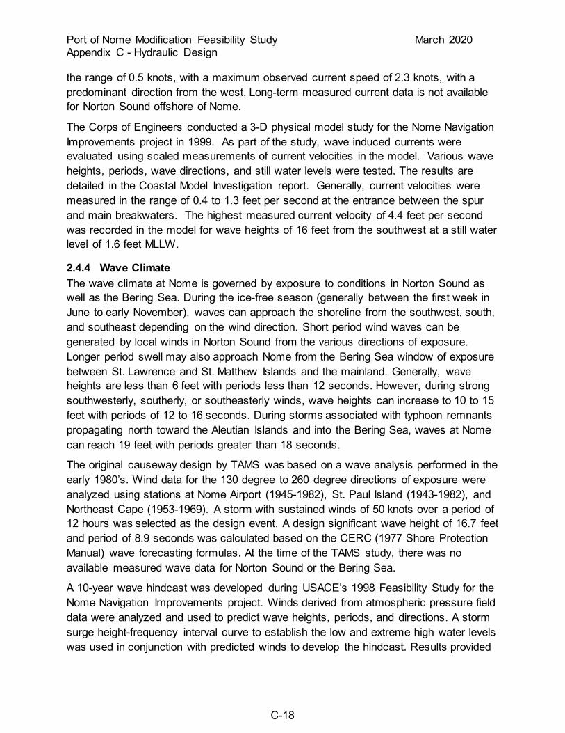
the range of 0.5 knots, with a maximum observed current speed of 2.3 knots, with a predominant direction from the west. Long-term measured current data is not available for Norton Sound offshore of Nome.
The Corps of Engineers conducted a 3-D physical model study for the Nome Navigation Improvements project in 1999. As part of the study, wave induced currents were evaluated using scaled measurements of current velocities in the model. Various wave heights, periods, wave directions, and still water levels were tested. The results are detailed in the Coastal Model Investigation report. Generally, current velocities were measured in the range of 0.4 to 1.3 feet per second at the entrance between the spur and main breakwaters. The highest measured current velocity of 4.4 feet per second was recorded in the model for wave heights of 16 feet from the southwest at a still water level of 1.6 feet MLLW.
2.4.4 Wave Climate The wave climate at Nome is governed by exposure to conditions in Norton Sound as well as the Bering Sea. During the ice-free season (generally between the first week in June to early November), waves can approach the shoreline from the southwest, south, and southeast depending on the wind direction. Short period wind waves can be generated by local winds in Norton Sound from the various directions of exposure. Longer period swell may also approach Nome from the Bering Sea window of exposure between St. Lawrence and St. Matthew Islands and the mainland. Generally, wave heights are less than 6 feet with periods less than 12 seconds. However, during strong southwesterly, southerly, or southeasterly winds, wave heights can increase to 10 to 15 feet with periods of 12 to 16 seconds. During storms associated with typhoon remnants propagating north toward the Aleutian Islands and into the Bering Sea, waves at Nome can reach 19 feet with periods greater than 18 seconds.
The original causeway design by TAMS was based on a wave analysis performed in the early 1980’s. Wind data for the 130 degree to 260 degree directions of exposure were analyzed using stations at Nome Airport (1945-1982), St. Paul Island (1943-1982), and Northeast Cape (1953-1969). A storm with sustained winds of 50 knots over a period of 12 hours was selected as the design event. A design significant wave height of 16.7 feet and period of 8.9 seconds was calculated based on the CERC (1977 Shore Protection Manual) wave forecasting formulas. At the time of the TAMS study, there was no available measured wave data for Norton Sound or the Bering Sea.
A 10-year wave hindcast was developed during USACE’s 1998 Feasibility Study for the Nome Navigation Improvements project. Winds derived from atmospheric pressure field data were analyzed and used to predict wave heights, periods, and directions. A storm surge height-frequency interval curve to establish the low and extreme high water levels was used in conjunction with predicted winds to develop the hindcast. Results provided

Port of Nome Modification Feasibility Study March 2020 Appendix C - Hydraulic Design
C-19
a range of wave heights, periods, directions, and frequencies of occurrence of waves at a point offshore from Nome in water depths of approximately 30 feet. The numerical models WISWAVE and STWAVE were then used to transform the offshore wave characteristics to the navigation improvements project site. Two water levels were used in the analysis: 0 foot MLLW and +13 feet MLLW. Wave directions were consolidated into three groups. The percentage of time of occurrence for each directional group during the 7-month ice-free season was determined for each of the two water levels. The predominant wave directions, after accumulating them into direction bins, were from 15 degrees east and 30 degrees west of due south. Wave heights were predicted to exceed 3.3 feet (1 meter) about 48 percent of the time total (31.8 percent from the southwest, 11.8 percent from the south, and 4.4 percent from the southeast). The wave hindcast also identified extremal wave heights using the sample range of 1976 through 1996 for storm events. The 50-year wave height at a water level of +13 feet MLLW was determined to be 19 feet with wave periods of up to 16 seconds. For purposes of developing test wave conditions for physical model studies of the navigation improvements project, wave periods of 9, 12, and 16 seconds were used.
An updated wave hindcast was performed by USACE’s ERDC. Wave height results based on 1985-2014 wind and pressure fields for Station 82100 are applicable for the Nome area. This station is located south-southwest of Nome in water depths of approximately 65 feet. The 50-year wave height is estimated at 21.9 feet as shown in Figure 5. Wave periods in the 10 to 12 second range were estimated. The percentage of time of occurrence for each directional group during ice-free conditions was determined from station 82100 data. Ice-free conditions were defined as any period when the ice concentration level was greater than 70 percent. The significant wave directions for the Nome harbor were west (247.5deg-292.5deg), southwest (202.5deg-247.5deg), south (157.5deg-202.5deg), southeast(112.5deg-157.5deg), and east(67.5deg-112.5deg). Wave heights for this WIS station were predicted to exceed 3 feet about 33.3 percent of the time total (1.8 percent from the west, 4.6 percent from the southwest, 5.2 percent from the south, and 4.0 percent from the southeast, and 3.7 percent from the east).

Port of Nome Modification Feasibility Study March 2020 Appendix C - Hydraulic Design
C-20
Figure 9: Location of WIS station 82100

Port of Nome Modification Feasibility Study March 2020 Appendix C - Hydraulic Design
C-21
Figure 10: Analysis figure for WIS station 82100 (Jensen, 2014)
For purposes of this study, the 50-year design wave height of 19 feet used for the navigation improvements project was selected for causeway armor stone stability design. For purposes of evaluating wave diffraction around the proposed causeway head, a range of wave periods varying from 6 seconds to 12 seconds was selected.
2.5 Hydrology The Snake River is the predominant drainage in the project vicinity. It discharges into Norton Sound through the Spit and the navigation channel between the causeway and the main breakwater. The approximate drainage area of the basin is 86 square miles and the average daily discharge is less than 500 feet per second during the summer months. During breakup, however, peak discharges may increase up to 3,000 cubic feet per second. Dry Creek and Bourbon Creek also drain into the project area and discharge through culverts beneath Seppala Drive into the back portion of the small boat harbor. Both creeks provide an average of less than 20 cubic feet per second discharge contribution to the system during average summer conditions. Similar to the Snake River, their flows increase during breakup with snowmelt conditions.

Port of Nome Modification Feasibility Study March 2020 Appendix C - Hydraulic Design
C-22
According to the Fourth National Climate Assessment (2017, Vol. 1), evidence for changes in maximum gauged streamflows is mixed, with a majority of locations having no significant trend. There is significance for seasonal changes in the timing of peak flows in interior Alaska, though increases in the absolute magnitude are not well evident in existing data.
Snake River discharge is diffused into the inner harbor areas and has only minor impacts on the inner harbor facilities. Outer harbor hydrodynamics are driven by wind and waves conditions. Snake River current impacts to the outer harbor and offshore environment are negligible as the flow is dispersed over an area much larger than the conveyance capacity of the river channel. The climate change induced increases in river current are also expected to have negligible impact to the Outer Basin and Deep Water Basin areas for the same reason.
The Snake River typically freezes up during the end of November each year. Earlier freeze-ups can occur during late September to any time in October depending on seasonal weather patterns. The upstream portion of the river tends to freeze up first while the downstream portion near the mouth at the navigation channel freezes last. Spring break-up of the river typically occurs in mid-May prior to break-up of the pack ice in Norton Sound. With increased river discharge in May, open leads begin to form in the navigation channel and tend to accelerate the pack ice breakup between the causeway and main breakwater. Little ice from the river itself flows down the channel to the mouth and river ice jams have not been observed in the area.
2.6 Ice Conditions Ice conditions within the project area include sea ice and shore fast ice. For the Nome area, sea ice formation typically occurs in early November each year; however, there have been years in which freeze-up in Norton Sound took place in mid-October. Spring break-up typically occurs in late May. Fast ice is sea ice of any origin that remains attached to shoreline features along the coast such as the existing breakwater, causeway, and seawall. Fast ice typically extends out from shore from 0.5 mile to approximately 7 miles depending on seasonal conditions. Near shore, the ice tends to be relatively smooth out to about 0.25 mile. From there the ice tends to become buckled offshore where the influence of pressure ridges are evident. Areas of large pressure ridges and possibly grounded pack ice have been observed in recent years at the entrance to the navigation channel between the spur and main breakwaters. Early winter ice sheet thicknesses of approximately 1 foot are typical. Maximum thicknesses of approximately 4.5 feet are predicted from computed freezing-degree-day estimates of ice growth. During years where pressure ridges are formed, estimated ice thicknesses at the ridges have been as great as 30 feet.

Port of Nome Modification Feasibility Study March 2020 Appendix C - Hydraulic Design
C-23
The National Oceanic and Atmospheric Administration (NOAA) began publishing an annual, peer-reviewed Arctic Report Card in 2006. The 2018 Report Card states that the Arctic sea ice cover is continuing to decline in the summer maximum extent and winter minimum extent (Perovich, et al., 2018). The minimum sea ice extent usually occurs in late September. In 2018, the ice cover was 26% lower in late September than the average coverage between 1981 and 2010 and was tied for the 6th lowest ice cover since 1979 (Perovich, et al., 2018). With a decreased sea ice extent there is an increased in time that the sub-arctic (i.e. Norton Sound) is ice-free or has limited sea ice coverage. A longer ice-free season could potentially expose the region to additional storms and associated damages that would have been mitigated by ice cover.
2.7 Sedimentation Long-shore sediment transport was evaluated during the 1998 feasibility study. The predominant direction of littoral sediment movement along the shoreline at Nome is from west to east. A volume of approximately 120,000 cubic yards per year (gross) of material transported along the shoreline was estimated. The net west-to-east transport volume of 60,000 cubic yards per year was calculated and represents the deposition of material on the west side of the causeway.
As part of the 2006 navigation improvements project, three features were incorporated into the project for managing sediments: a west sediment trap, an east sediment trap, and an increased bridge span and deepened gap in the causeway. These features were designed in the physical model for the project at ERDC to transport and intercept sediments prior to reaching the navigation channel into the harbor. In addition, sediment management would also prevent the tip shoal at the seaward end of the causeway from growing larger and potentially impacting the wave focusing on the causeway navigation between the heads of the spur and main breakwater.
Following construction of the navigation improvements project, USACE has performed maintenance dredging annually in the navigation channel since 2007 (Table 5). The east sediment trap portion of the project has not required annual maintenance but has been dredged on an as needed/funds available basis. The west sediment trap has not been maintained and is not an active feature. Sediments from the channel maintenance dredging have been discharged on the beach east of the main breakwater since the late 2000’s. As a result, the steady buildup of the beach in front of the City of Nome has been observed along and in front of the rock seawall. This is an indication of the net sediment transport from west to east continuing after the completion of the navigation improvements project.
The Snake River’s contribution to the sediment load in the system was also analyzed during the 1998 feasibility study. A volume of 5,900 cubic yards of sediment per year was estimated to be contributed to the system by the river. The majority of this material

Port of Nome Modification Feasibility Study March 2020 Appendix C - Hydraulic Design
C-24
discharges into Norton Sound during spring break-up when ice cover is still present. River sediments are not expected to shoal and accumulate in the navigation channel.
Table 5: Maintenance Dredging Quantities since 2007 Harbor Expansion
Year Dredge Quantity (CY) 2007 26,200 2008 49,600 2009 12,800 2010 26,000 2011 31,300 2012 75,200 2013 20,600 2014 54,200 2015 116,500 2016 67,500 2017 82,500 2018 65,700
3.0 DESIGN CRITERIA
3.1 Design Vessel and Fleet A fleet spectrum was developed for the arctic region and is outlined in the Economics Appendix for this study. Expected fleet activities are delivery of fuel and freight to Nome and trans-shipment to surrounding communities and mineral resource extraction. Secondary fleet activities include search and rescue, and arctic research.
3.1.1 Bulk Fuel Delivery Support vessels deliver fuels to upland storage tanks that supply Nome and local communities with motor vehicle fuels, jet fuel and heating oil. Currently the vessels delivering these fuels are shallow draft fuel barges due to the limited depths of the existing harbor. With deep draft docks the fuels deliveries would be made with oceangoing tankers that have significantly larger capacities than the barges. The characteristic vessel identified for fuel delivery at the deepened Outer Basin is a handi-size tanker (length 575 feet, beam 96 feet, maximum draft 31.2 feet, light-loaded draft 21.5 feet) similar to the Maersk Belfast. This tanker would have to arrive at the Outer Basin docks light loaded due to depth restrictions. The characteristic vessel identified for fuel delivery at the Deep Water Basin is a handi-size tanker (length 572 feet, beam 91 feet, maximum draft 34.9 feet, light-loaded draft 24 feet) similar to the Chembulk New Orleans. This tanker would have to arrive at the Deep Water Basin docks light loaded due to depth restrictions.
Port of Nome Modification Feasibility Study March 2020 Appendix C - Hydraulic Design
C-25
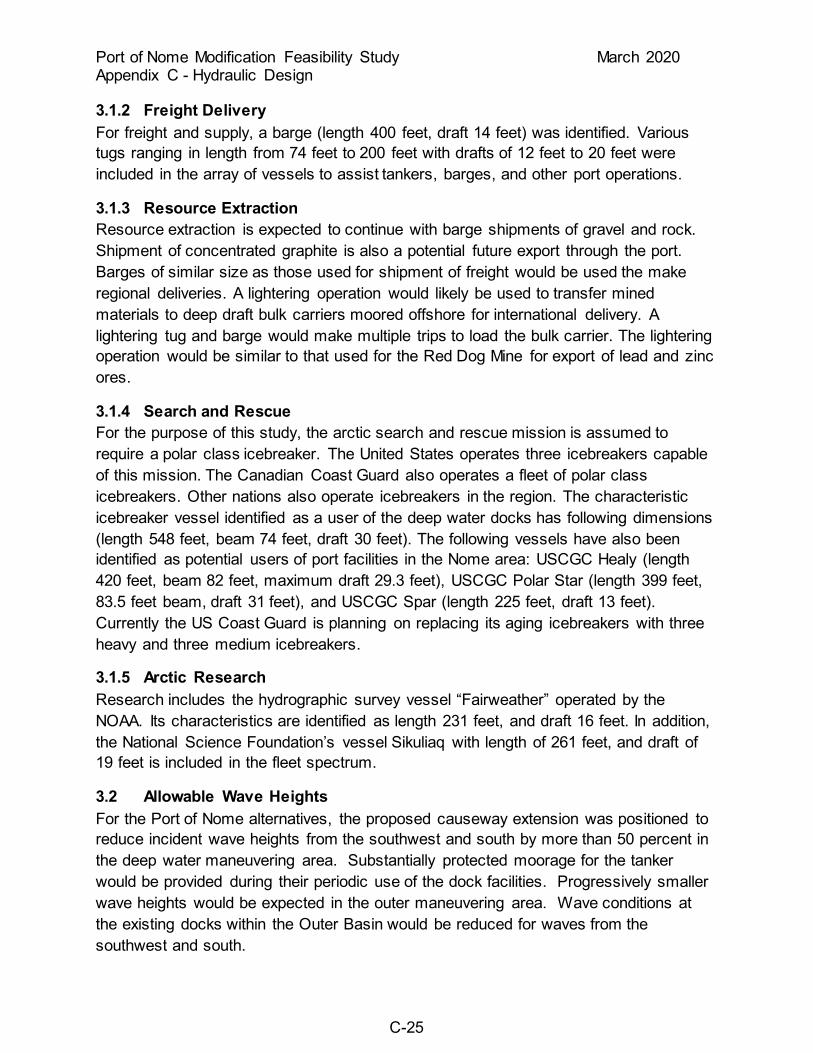
3.1.2 Freight Delivery For freight and supply, a barge (length 400 feet, draft 14 feet) was identified. Various tugs ranging in length from 74 feet to 200 feet with drafts of 12 feet to 20 feet were included in the array of vessels to assist tankers, barges, and other port operations.
3.1.3 Resource Extraction Resource extraction is expected to continue with barge shipments of gravel and rock. Shipment of concentrated graphite is also a potential future export through the port. Barges of similar size as those used for shipment of freight would be used the make regional deliveries. A lightering operation would likely be used to transfer mined materials to deep draft bulk carriers moored offshore for international delivery. A lightering tug and barge would make multiple trips to load the bulk carrier. The lightering operation would be similar to that used for the Red Dog Mine for export of lead and zinc ores.
3.1.4 Search and Rescue For the purpose of this study, the arctic search and rescue mission is assumed to require a polar class icebreaker. The United States operates three icebreakers capable of this mission. The Canadian Coast Guard also operates a fleet of polar class icebreakers. Other nations also operate icebreakers in the region. The characteristic icebreaker vessel identified as a user of the deep water docks has following dimensions (length 548 feet, beam 74 feet, draft 30 feet). The following vessels have also been identified as potential users of port facilities in the Nome area: USCGC Healy (length 420 feet, beam 82 feet, maximum draft 29.3 feet), USCGC Polar Star (length 399 feet, 83.5 feet beam, draft 31 feet), and USCGC Spar (length 225 feet, draft 13 feet). Currently the US Coast Guard is planning on replacing its aging icebreakers with three heavy and three medium icebreakers.
3.1.5 Arctic Research Research includes the hydrographic survey vessel “Fairweather” operated by the NOAA. Its characteristics are identified as length 231 feet, and draft 16 feet. In addition, the National Science Foundation’s vessel Sikuliaq with length of 261 feet, and draft of 19 feet is included in the fleet spectrum.
3.2 Allowable Wave Heights For the Port of Nome alternatives, the proposed causeway extension was positioned to reduce incident wave heights from the southwest and south by more than 50 percent in the deep water maneuvering area. Substantially protected moorage for the tanker would be provided during their periodic use of the dock facilities. Progressively smaller wave heights would be expected in the outer maneuvering area. Wave conditions at the existing docks within the Outer Basin would be reduced for waves from the southwest and south.

Port of Nome Modification Feasibility Study March 2020 Appendix C - Hydraulic Design
C-26
During periods of southeasterly wave exposure, the outer maneuvering area would still be exposed to somewhat reduced wave heights as a result of diffraction around the head of the causeway extension. However, the west causeway extension would provide little if any additional wave climate reductions of southeast or easterly wave directions for the Deep Water or the Outer Basins. However, often during storms that generate high water levels, winds shift from southeasterly to southerly. As this shift progresses, the wave protection effects of the extended west causeway would be accentuated.
Analysis of wave height reductions due to the causeways and breakwaters was conducted using diffraction analysis. Wave data is estimated for design significant wave height, peak period and water depths. The wave date is then used to properly scale diffraction diagrams to the causeway and breakwater layouts. Wave reduction factors are taken from the scaled diffraction diagrams to determine the wave climate for each channel and basin area based on the incident wave conditions outside of the port.
Long-period wave energy and harbor oscillation are not expected to be problematic in the port alternatives. Long period waves that drive port oscillations would be dissipated on the shallow angle beach at the north end of the outer basin and long sections of rubble-mound causeway slope that line a significant majority or the basin perimeter. Wave periods exceeding 12 seconds are rare, 1.4% occurrence based WIS data. The reflective vertical sheet pile walls of the ship docks will reflect wave energy within the basin but their percentage of the basin perimeter is small and their effects will be limited.
Due to the anticipated periodic use of the deep water and outer maneuvering area and the design vessel that would use the proposed dock facilities, wave height criteria have been established accordingly. In general, wave heights of 3 feet or less in the maneuvering area for large vessels has previously been applied during the 1998 Nome Navigation Improvements project as the criteria for designing wave protection structures. For this study, an allowable wave height of 3 feet for the docks and mooring areas and 6 feet for the deep water entrance channel was determined to be acceptable for the design vessel transiting the area. Wave periods exceeding 8-10 seconds would also limit docking and unloading operations. Periodically, wave heights will exceed the allowable wave height, particularly when the wave is oriented more southeasterly; during these conditions vessel docking and loading operations at the new dock facilities would cease until conditions improve. For the Outer Basin area at the existing docks, wave heights of 3 feet were also selected for design; however, due to the enhanced wave protection provided by the causeway extension, estimated wave heights would be less than 1 foot for the majority of the time. During storm events with waves from due southeast, wave heights in the inner maneuvering area would be between 1 and 3.3 feet.

Port of Nome Modification Feasibility Study March 2020 Appendix C - Hydraulic Design
C-27
3.3 Channel and Basin Widths and Depths The entrance channel width requirements were determined by criteria given in EM 1110-2-1613 (USACE 2006). For a two-way channel with tidal current velocities of 1.5 to 3.0 knots, the width should be approximately 6.5 times the beam of the tanker design vessel (96 feet). For the proposed entrance channel at the Port of Nome alternative, a minimum bottom width of 624 feet would allow adequate maneuverability and clearance on each side of the causeway head and main breakwater head. This channel width was increased to 700 feet to take into account the wind effects, and wave conditions from the south and southeast. While it is not expected that the channel would frequently be used as a two-way traffic entrance for the design vessel, it is likely that traffic of varying beams would enter or exit the port at the same time periodically over the life of the project. In addition, the Nome alternative is configured with a common entrance channel for both the Deep Water and Outer Basins as well as the small boat harbor. Therefore, multiple vessels of varying beam dimensions and port uses would be expected to generate sufficient traffic to warrant the proposed channel width.
The entrance channel width for navigation into the Outer Basin area was determined based on the tanker design vessel expected to operate in and adjacent to the sheet pile docks. Multiplying the beam dimension of the tanker (96 feet) by a factor of 6.5, the required inner channel width was calculated to be 624 feet. Accounting for wind, traffic, and wave effects the channel width was increased to 650 feet.
Typically for deep draft navigation projects, physical modeling and ship simulator studies are required for channel design. Also, field data collection of ship maneuvering and wave motion is warranted. Due to schedule and budget limitations for this study, channel design was conducted using the best available guidance and analytical techniques.
The pitch heave and roll factor used in determining channel depths were estimated using empirically based methods for estimating vertical ship excursions in waves as defined in EM 1110-2-1613. The calculation accounts for wave height and period, wave encounter angle, vessel information, and duration of wave encounter. Calculations assumed the design vessel would have a natural pitch period of 10 seconds, speed of 4 knots, traveling through 6 foot waves.
The outer channel depths were determined based on economic evaluations, design vessel draft, vessel motion in waves, squat, tide, safety clearance, advanced maintenance, and dredging tolerance. Two depths outer channel depths (-25 feet MLLW and -28 feet MLLW) were used to evaluate alternatives. For the deep water channel an array of three channel depths were used to evaluate alternatives (-30 feet MLLW, -35 feet MLLW, and -40 feet MLLW).
Port of Nome Modification Feasibility Study March 2020 Appendix C - Hydraulic Design
C-28
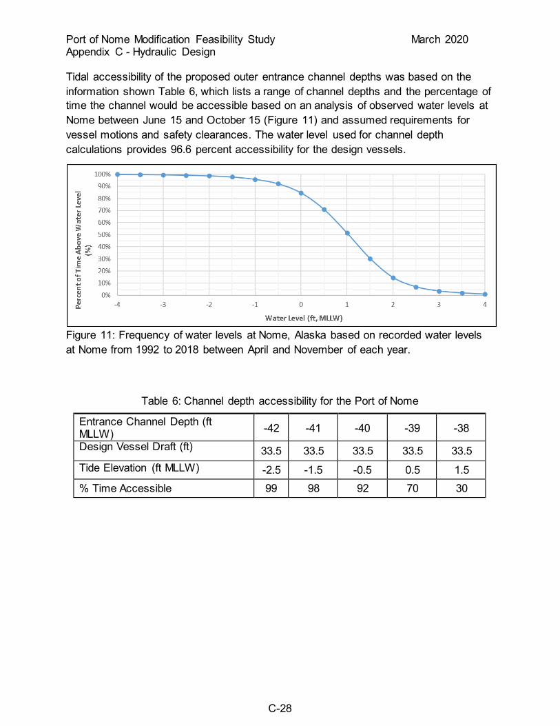
Tidal accessibility of the proposed outer entrance channel depths was based on the information shown Table 6, which lists a range of channel depths and the percentage of time the channel would be accessible based on an analysis of observed water levels at Nome between June 15 and October 15 (Figure 11) and assumed requirements for vessel motions and safety clearances. The water level used for channel depth calculations provides 96.6 percent accessibility for the design vessels.
Figure 11: Frequency of water levels at Nome, Alaska based on recorded water levels at Nome from 1992 to 2018 between April and November of each year.
Table 6: Channel depth accessibility for the Port of Nome
Entrance Channel Depth (ft MLLW) -42 -41 -40 -39 -38 Design Vessel Draft (ft) 33.5 33.5 33.5 33.5 33.5 Tide Elevation (ft MLLW) -2.5 -1.5 -0.5 0.5 1.5 % Time Accessible 99 98 92 70 30

Port of Nome Modification Feasibility Study March 2020 Appendix C - Hydraulic Design
C-29
Table 7: Deep water -30 foot MLLW Channel Depth
Channel Criteria Value (ft) Access at 96.6% of tide stages (based on recorded tide data) -0.5 MLLW Maximum Vessel Draft 23.5 Pitch, Roll, and Heave 3.5 Squat 0.5 Safety clearance (based on sand/gravel bottom) 2.0 Entrance Channel Depth -30.0 MLLW
Table 8: Deep Water -35 foot MLLW Channel Depth
Channel Criteria Value (ft) Access at 96.6% of tide stages (based on recorded tide data) -0.5 MLLW Maximum Vessel Draft 28.5 Pitch, Roll, and Heave 3.5 Squat 0.5 Safety clearance (based on sand/gravel bottom) 2.0 Entrance Channel Depth -35.0 MLLW
Table 9: Deep Water -40 foot MLLW Channel Depth
Channel Criteria Value (ft) Access at 96.6% of tide stages (based on recorded tide data) -0.5 MLLW Maximum Vessel Draft 33.5 Pitch, Roll, and Heave 3.5 Squat 0.5 Safety clearance (based on sand/gravel bottom) 2.0 Entrance Channel Depth -40.0 MLLW
Port of Nome Modification Feasibility Study March 2020 Appendix C - Hydraulic Design
C-30
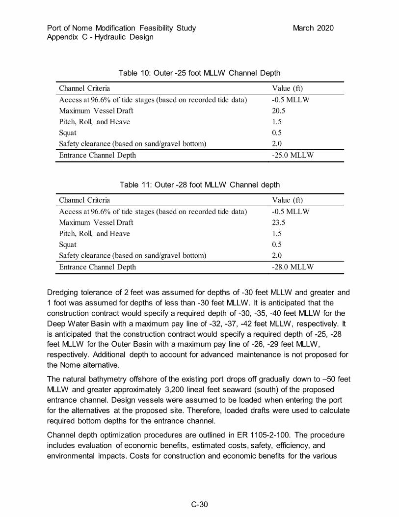
Table 10: Outer -25 foot MLLW Channel Depth
Channel Criteria Value (ft) Access at 96.6% of tide stages (based on recorded tide data) -0.5 MLLW Maximum Vessel Draft 20.5 Pitch, Roll, and Heave 1.5 Squat 0.5 Safety clearance (based on sand/gravel bottom) 2.0 Entrance Channel Depth -25.0 MLLW
Table 11: Outer -28 foot MLLW Channel depth
Channel Criteria Value (ft) Access at 96.6% of tide stages (based on recorded tide data) -0.5 MLLW Maximum Vessel Draft 23.5 Pitch, Roll, and Heave 1.5 Squat 0.5 Safety clearance (based on sand/gravel bottom) 2.0 Entrance Channel Depth -28.0 MLLW
Dredging tolerance of 2 feet was assumed for depths of -30 feet MLLW and greater and 1 foot was assumed for depths of less than -30 feet MLLW. It is anticipated that the construction contract would specify a required depth of -30, -35, -40 feet MLLW for the Deep Water Basin with a maximum pay line of -32, -37, -42 feet MLLW, respectively. It is anticipated that the construction contract would specify a required depth of -25, -28 feet MLLW for the Outer Basin with a maximum pay line of -26, -29 feet MLLW, respectively. Additional depth to account for advanced maintenance is not proposed for the Nome alternative.
The natural bathymetry offshore of the existing port drops off gradually down to –50 feet MLLW and greater approximately 3,200 lineal feet seaward (south) of the proposed entrance channel. Design vessels were assumed to be loaded when entering the port for the alternatives at the proposed site. Therefore, loaded drafts were used to calculate required bottom depths for the entrance channel.
Channel depth optimization procedures are outlined in ER 1105-2-100. The procedure includes evaluation of economic benefits, estimated costs, safety, efficiency, and environmental impacts. Costs for construction and economic benefits for the various

Port of Nome Modification Feasibility Study March 2020 Appendix C - Hydraulic Design
C-31
channel depths were evaluated in the Economic Appendix. Refer the Economics Appendix for discussion of channel depth optimization.
3.4 Circulation The circulation aspects of the proposed causeway extension at Nome were evaluated based on guidance given in EM 1110-2-1202 (USACE 1987). Tidal variation, storm surge, fresh water input from the Snake River, wave driven currents, ice effects, and wind stresses are factors that affect water circulation. It is estimated that the predominant mechanism that would drive water circulation would be wave and wind stress induced currents within the maneuvering areas and entrance channel. Tidal variation at Nome is relatively small; however, storm surge events pump significant volumes of water into the Snake River estuary. Strong onshore winds and high surf waves are usually associated with storm surges and would represent the larger water circulation component under such conditions. Secondarily, the ebb drawdown of the volume of water in the estuary would also drive circulation.
The aspect ratio (length divided by width) of the existing port at Nome seaward of the sand spit is approximately 3:1. With the causeway extension this would be increased to approximately 3.5:1. With the breaches in both the existing causeway and main breakwater at the -6.5-foot MLLW contour and the entrance channel essentially open to Norton Sound, the outer portion of the Port is not configured as an enclosed harbor. Therefore, planform geometry would not be an integral factor in determining circulation parameters. However, the guidance for harbor circulation can be applied in a general sense for this study. It has been shown that aspect ratios of less than 3:1 reduce the potential for multiple circulation gyres to decrease the gross water exchange between the basin and ambient water. Another parameter used to evaluate harbor circulation is the ratio of the basin planform area (A) to the entrance cross-sectional area (a). Guideline values of A/a and A/a1/2w are given in Nece 1979. Typical values recommended are A/a < 400 and A/a1/2w < 100 to ensure optimal basin configuration for flushing. Guideline values calculated for the alternatives carried forward for detailed design are shown in Table 12.
Table 12: Indicator aspect ratios for circulation analysis
Alternative Aspect Ratio A/a A/a1/2w
3A 2.3:1 77 17 4 1.7:1 75 14 8A 1.4:1 190 42 8B 1.4:1 190 42

Port of Nome Modification Feasibility Study March 2020 Appendix C - Hydraulic Design
C-32
Rounding of basin corners may have some slight benefits in reducing local exchange in the “hot spots.” Also, the orientation and location of a single, central entrance channel is generally favorable in driving harbor circulation. In addition, the areas of potentially low exchange in the corners of the basin can be checked to ensure that no more than 5 percent of the total areas have exchange coefficients less than 0.15. For the Nome alternative, the northwest and northeast corners are naturally rounded beach areas, and the proposed causeway extension was designed with a radius of 200 feet. The outer maneuvering area would basically be open to Norton Sound to the east.
Typically for deep draft navigation projects, physical and numerical modeling studies are recommended in order to analyze the hydrodynamics of proposed channel improvements. For this study, circulation was evaluated using the best available guidance and analytical techniques. Detention time, volume of water exchange, mixing, dilution, and stratification would not be expected to change significantly with the Nome causeway extension alternative.
3.5 Ice Forces The Port of Nome Design Memorandum by TAMS incorporated an ice engineering investigation. The objectives were to identify, evaluate, and design for ice-sheet and ice-ridge interactions with the proposed port. In addition, ice loadings on the port facilities were estimated. Ice design parameters for the project were determined as follows:
• Maximum ice-sheet thickness o Mobile, mid to late winter 3.0 feet o Landfast, all season, and mobile late spring 4.5 feet
• Velocity o Maximum, moving ice-sheet 2.5 feet per second o Mean 0.7 feet per second
• Strength o Flexural 102 pounds per square inch o Shear 55 pounds per square inch o Loading 110 kips per foot
Ice ride-up accumulations of up to 30 feet on the causeway crest were estimated based on test runs of the physical model.
For this study, the data from the TAMS analysis were applied for the proposed causeway extension. The existing causeway has performed well since its construction in the mid-1980s, and there have been several significant ice ridge-ups during that period. In the spring of 2001, southeasterly winds created moving ice-sheet conditions that overrode the causeway and built up accumulations of approximately 25 feet in

Port of Nome Modification Feasibility Study March 2020 Appendix C - Hydraulic Design
C-33
height at the head and south bridge abutment. Also, during the winter of 2005 a large ice pressure ridge formed at the entrance between the causeway head and main breakwater from moving ice-sheet forces. This feature was approximately 30 feet in height above the MLLW elevation and likely was grounded on the seafloor at -25 feet MLLW. A similar ice pressure ridge formation occurred during the winter of 2012 although its magnitude was not a great. Since the proposed causeway extension and dock structure are similar in design to the original port project, it is expected that they would perform equally as well. The “A5” armor stone was shown to be stable in the physical model under design ice loading conditions.
3.6 Life-Cycle Causeway Extension/Breakwater Design
3.6.1 Port of Nome Life-Cycle Design Armor stone for the proposed causeway extension at Nome was sized using the 50-year design wave and ice forces expected to impinge on the structure. This was determined to be the most cost-effective means of protection for port alternatives considered. The average sea side armor stone size for a 25-year design is 11.7 tons, 50-year design is 22 tons, and for a 100-year design is 26.8 tons. There is a 2 percent chance of a 50-year design event happening in any given year throughout the 50-year period of analysis. The chance goes up to 4 percent for a 25-year design. The percentage goes down to 1.3 percent for a 75-year design level and to 1 percent if a 100-year design level is used. There is minimal difference in cost between armor stone sized for a 25-year event versus a 50-year event. Rock for the project would likely either be barged or trucked from the local quarry at Cape Nome to the project location. If the construction contractor selected a quarry other than Cape Nome as the rock source, the rock would be barged to the site for placement. The Cape Nome quarry in the project vicinity has the capacity to produce armor stone for either a 25-year event or a 50-year event. Using the 25-year design, it is estimated that overall cost savings throughout the project period of analysis would not be realized due to higher operations and maintenance replacement costs. Replacement costs are estimated to be relatively high because the project location is relatively remote and mobilization costs are substantial. A 75 or 100-year design would reduce the frequency and magnitude of needed maintenance. A 50-year design provides the optimum balance between minimizing maintenance requirements and the cost of procuring the stone for repairs. The loss or damage to a relatively small amount of armor stone over time would have little to no effect on the operation and use of the port; therefore, there was not sufficient justification for basing the design on a life-cycle horizon beyond the 50-year level.
3.7 Dredging Dredging limits were determined based on vessel maneuvering characteristics as a function of length, beam, whether or not tug assist would be provided, turning radii,

Port of Nome Modification Feasibility Study March 2020 Appendix C - Hydraulic Design
C-34
traffic, and wind conditions. Side slopes of 3H:1V were assumed for Nome based on the character of dredged material anticipated (sands, gravel, cobbles, boulders, and glacial till). Such side slopes would be stable and rock slope protection would not be necessary for placement on the side slopes.
A minimum offset bench width distance of 15 feet horizontal between the top of the dredge cut slope and the toe of any causeway or breakwater structure is recommended. For purposes of dredging adjacent to the proposed dock faces, the required depth can abut to the dock faces.
Dredging tolerances vary with depth. For dredging areas with a required depth -30 feet MLLW and deeper, a tolerance of 2 feet was used. For areas where the required depth is less than -30 feet MLLW, a tolerance of 1 foot was used.
4.0 MODEL STUDIES
4.1 Physical Modeling For purposes of this study, additional physical modeling for wave and ice analysis was beyond the scope, budget, and schedule. However, the results of previous modeling have been applied in general toward the proposed causeway extension for the Port of Nome alternative.
As part of the original Port of Nome causeway design by TAMS in 1982, a physical model of ice impacts was conducted at the Iowa Institute of Hydraulic Research (IIHR). The purpose of the ice engineering physical model was the following: (1) to study the ice impingement on the causeway and its head, (2) estimate ice loadings on the causeway and other port improvements, (3) determine armor stone stability under ice loading conditions, (4) determine the likely frequency of ice overtopping of the causeway and dock facilities, and (5) design ice protection and management strategies.
The model was constructed in two components. First, a 1:20 scale side slope 2-dimensional model was constructed to test ice impacts to an armored causeway section for stability. Second, a 3-dimensional 1:30 scale breach model was constructed to evaluate moving ice sheet impacts on the causeway breach. Ice movement in the vicinity of the breach was investigated for both an oblique 45 degree direction and a parallel direction of impact.
Results of the ice modeling showed three modes of ice failure: (1) flexural, (2) buckling, and (3) crushing. Both the causeway and breach armor stone requirements for stability were determined in the model. In addition, the causeway and breach crest elevations were established to accommodate ice overtopping events without sustaining damage.
A 3-dimensional physical model study was conducted at ERDC in 1998 for the navigation improvements project at Nome. The purpose of the physical model was the

Port of Nome Modification Feasibility Study March 2020 Appendix C - Hydraulic Design
C-35
following: (1) to study wave, current, and shoaling conditions at the existing harbor and with the proposed navigation improvements, (2) determine the impacts the proposed improvements would have on wave-induced current patterns and magnitudes, sediment transport, and wave conditions in the navigation channel, (3) optimize the length and alignment of the new breakwater, (4) optimize the length and alignment of the new causeway extension (spur breakwater), and (5) develop plans for addressing design wave and ice conditions as necessary.
The model was constructed to an undistorted linear scale of 1:90 (model to prototype). It reproduced waves, wave-induced currents, and sediment transport patterns along several thousand feet of shoreline with and without improvement components. The wave generator was designed to produce waves of various heights, periods, and directions in order to model the range of conditions anticipated.
Results of the modeling showed that major decreases in wave activity could be achieved with the proposed improvements. Both the spur and main breakwaters were shown to be required in order to reduce wave heights and currents to criteria levels and to control sedimentation within the navigation channel.
4.2 Numerical Modeling
4.2.1 Navigation Simulation Navigation simulation runs were performed at the Ship Simulator at the Coastal Hydraulics Laboratory from April 2 to April 10, 2019 by two Alaska Marine Pilots. Alaska Marine Pilots (Bill Gillespie and Rick Entenmann) contracted by the local sponsor, the City of Nome, piloted the simulator vessels during the April 2019 Nome Harbor Modification ship simulation.
The design assumptions below were tested during the navigation simulation study to define operational requirements, and channel and wave protection layout suitability.
• Two 1700 horsepower tugs would be needed to allow the design vessels to turn and dock at the planned Deep Water and Outer Basin docks.
• Channel widths of 700 feet would be sufficient for the design vessel entering the Deep Water Basin and alignment of the entrance channel into the Deep Water Basin would be navigable with tug assistance
• Channel widths of 650 feet would be sufficient for the design vessel entering the Outer Basin and alignment of the entrance channel into the Outer Basin would be navigable with tug assistance
• Turning basins with a diameter of 865 feet would be sufficient for the design vessels with tug assistance
Port of Nome Modification Feasibility Study March 2020 Appendix C - Hydraulic Design
C-36
4.2.1.1 Tug Power Two tugs were used for a most of the simulator runs. Both of the tugs were identical producing a 22 ton bollard push forward and a 17 ton bollard pull astern. Tug power was characterized by relating bollard push to horsepower with the formula T = 0.013BP which provides a nominal tug power of 1700 hp. Simulation run logs show that maximum tug power was used frequently for the high wind conditions that were modeled. The typical simulator run was conducted with a 25 knot wind from the southwest or southeast. This size of tug was selected based on current availability of vessels in the region. The sponsor and pilot indicated that tugs of this size would likely be available to assist with port operations, while it would be much less likely to find larger tugs that could operate for projected future operations.
Pilots indicated that arrivals for all of the alternatives would require two assist tugs. Pilots indicated on runs in all three alternatives that additional tug power would be needed to navigate the harbor under the high wind conditions that were run. Pilots noted a need for additional tug horsepower in alternative 3A and 4A more frequently than alternative 8B.
4.2.1.2 Channel Width The channels for all the harbor alternatives were designed in accordance with USACE engineering manuals and regulations. All entrance channels and turning basins meet or exceed the requirements of EM 1110-2-1613 and ER 1110-2-1404. Per EM 1110-2-1613, Using a design vessel length of 575 feet, the minimum turning basin width is 690 feet for currents under 0.5 knots and 863 feet for currents under 1.5 knots. The EM provides the following provisions to consider increasing recommended minimum widths: for operations of tankers in ballast condition, design wind speeds greater than 25 knots or changes to accommodate local operational considerations.
It should be noted that deep water basin and outer basin dock locations have minimal wind shelter since the Port of Nome is built seaward from the shoreline. Wind speeds may have a greater influence on vessel maneuverability inside the Port of Nome than at typical US port locations. Pilot input was heavily relied upon when making decisions concerning effectiveness of harbor operations.
4.2.1.3 Deep Water Basin Alternatives 3A, 4A, and 8B tested in the simulator all have entrance channels of 700 feet in width into the Deep Water Basin. The turning basin within the alternative 3A and 4A Deep Water Basin, excluding moorage areas is 865 feet. Due to the nearly identical layout of 3A and 4A runs for alternative 3A were not conducted. The turning basin within the 8B Deep Water Basin, excluding moorage areas, is 1105 feet. The pilots were able to successfully bring their ships to the Deep Water Basin docks of Alternative 4A in 19 out of 21 runs. The pilots were able to successfully bring their ships to the Deep Water

Port of Nome Modification Feasibility Study March 2020 Appendix C - Hydraulic Design
C-37
Basin docks of Alternative 8B in 21 out of 25 runs. Pilots indicated that the turn into the Deep Water Basin of alternative 3A and 4A was tight and that they needed more room to slow the vessel.
4.2.1.4 Outer Basin The entrance channel width and turning basin width within the alternative 3A Outer Basin, excluding moorage areas, is 550 feet and 1045 feet, respectively. The entrance channel width and turning basin width within the alternative 4A Outer Basin, excluding moorage areas, is 825 feet and 1045 feet, respectively. The entrance channel width and turning basin width within the alternative 8B Outer Basin, excluding moorage areas, is 605 feet and 1620 feet, respectively. The pilots were able to successfully bring their ships to the Outer Basin docks of Alternative 3A in 8 out of 10 runs. The pilots were able to successfully bring their ships to the Outer Basin docks of Alternative 4A in 14 out of 20 runs. The pilots were able to successfully bring their ships to the Outer Basin docks of Alternative 8B in 18 out of 22 runs.
The pilots indicated that the turn into the Outer Basin of alternative 3A and 4A was hard to maintain a safety clearance of 200 feet off the east causeway/breakwater and that they needed more room in the turning basin. Pilot comments also frequently note that many simulation runs into the Outer Basin of 4A would not have been attempted using actual vessels under the environmental conditions simulated. The simulations were performed to help understand how restrictive alternatives 3A and 4A were to operations. The pilots also indicated that many of the successful runs were only completed through very precise maneuvers that did not allow any misjudgment of vessel conditions or for changes in environmental conditions during the maneuvers. In summary, the pilots would not consider performing these maneuvers in alternatives 3A or 4A should these projects be constructed.
4.2.1.5 Pilot Comments The Alaska Marine Pilots LLC submitted a letter to the District (Attachment 3) on August 27, 2019 which expands on the summary comments provided at the ship simulator. The letter discusses pilot concerns over the utility of alternative 4A due to its inability to accommodate large cruise ships such as the Crystal Serenity (820 ft Length x 106 ft Beam x 30 ft Draft), operations during severe weather condition, adequacy of the entrance channels and turning basins, and unsafe conditions during tanker turns and docking in the Deep Water Basin of alternative 4A (i.e. Use full stopping power from assist tugs and vessel astern power to stop the vessel).
The pilot letter stated a concern that Alternative 4A does not have adequate maneuvering room and every dock must be vacated of moored vessels. The layout of the entrance channels for alternatives 4A and 8B differ but the channel widths, radii, and deflection angles are nearly identical. The turning basin dimensions of alternative

Port of Nome Modification Feasibility Study March 2020 Appendix C - Hydraulic Design
C-38
4A meet minimum USACE design requirements. The turning basin dimensions of alternative 8B significantly exceed the design requirements due to the much larger alternative footprint. While the pilots were able to successfully navigate the outer basin of 4A with vessels on other docks, these runs required precise maneuvers and would not have been attempted with actual vessels for the reasons discussed above.
Another pilot concern was that Alternative 4A allows for operations only in the best of weather conditions. Ship simulation pilots successfully piloted the design vessels to dock in wind speeds ranging from 15 to 25 knots, currents of 1.5 knots, wave heights of 6 feet, and vessels at dock narrowing approach channels. According to Nome airport weather records a 25 knot wind speed is only exceeded 0.4 percent of the time during the months of May through October for the 1948-2019 period of record. The pilots also noted that airport winds are usually not as strong as winds on the dock and they experience higher wind speeds more frequently than indicated by the airport wind data analysis.
Another pilot concern was that a very unsafe condition of full stopping power of assist tug and vessel astern power were required to stop the vessel in the Deep Water Basin of Alternative 4A. During the simulation runs, the tugs were usually positioned perpendicular to the vessel to provide maximum effort towards turning or rotating the vessel. Runs performed with tug assisted deceleration could not be extracted from the data to analyze. The pilots noted that tug assisted deceleration was primarily tested in the Deep Water Basin runs with loaded vessels. The concern with max vessel and max tug power use for deceleration is that there would be no margin for error; if deceleration operations were initiated too late in the dock approach or stern winds increased, there would be no means to prevent the vessel from colliding with the structure
An analysis of the ship simulation log files was conducted to verify use of maximum tug horse power and astern vessel power during arrival simulations. A review of the simulation run data and discussions with the pilots indicates that pilot decisions to use max stern thrust was not recorded in the simulation data. Analysis of engine power and revolutions per minute appeared to under report these decisions based on simulator participant recollections and are not considered good indicators.
Analysis results indicate that maximum tug horsepower was used in nearly all of the runs for alternatives 4A and 8B. Maximum tug horsepower was used in 27 of the 40 total runs for alternative 4A. Maximum tug horsepower was used in 45 of the 47 total runs for alternative 8B. Comparison of the percent usage of maximum tug horsepower in the Deep Water Basin indicated similar usage in alternative 4A and 8B runs. Further discussion with the pilots indicates that maximum tug power is commonly used to turn vessels to align with the dock. This operation is not considered unsafe as the vessel has already decelerated and is under tug power. The common use of max tug power during turning operations skews the data because nearly all runs used the tugs to turn
Port of Nome Modification Feasibility Study March 2020 Appendix C - Hydraulic Design
C-39
the vessel. The percentage of tug power use for turning versus deceleration could not be distinguished in the data.
Based on the pilot concern that, use of maximum assist tug power is considered a very unsafe condition, it is recommended that more powerful tugs than those used in the ship simulations (1700 horsepower) be used in the new harbor. The availability of tugs was not studied during this effort, however both the sponsor and the pilots indicated that it would be difficult to find and sustain tugs larger than the 1700 hp size at Nome due to vessel availability and the expected frequency of use.
Pilot comments during the ship simulator suggested tolerable wind speeds for navigation through Alternative 4A would be 10 knots and wind speeds for 8B would be 20 knots. Based on the airport wind analysis, pilot wind speed requirements to navigate the harbor for 4A would be exceeded 36.3% of the time during the open water season, whereas conditions to navigate 8B would be exceeded 2.6% of the time.
5.0 ALTERNATIVES See the Attachments Section at the end of this appendix for plan and section view figures for the alternatives.
5.1 Port of Nome Expansion A range of alternative designs was considered for deep draft navigation improvements at the existing Port of Nome. A matrix of possible alternatives for consideration was developed in the initial phase of the study that included various configurations of modifications and/or extensions of the existing causeway, main breakwater, and dredging. This phase narrowed down the alternative designs to the basic concept alternative: extension of the causeway offshore with an “L-shaped” segment at the head, dredging a new deep water entrance channel and deepening the existing outer maneuvering area and channel, and construction of new dock facilities to support the fleet. Several variations of this basic concept alternative were analyzed with replacement of the existing breakwater to the east with a new causeway with docks. No sites other than the existing port site were explored in detail for consideration.
The alternatives were evaluated using established design guidance given in the appropriate USACE Engineering Manuals (EM’s) and the Coastal Engineering Manual (CEM). Physical modeling of the alternatives was not included in the scope of this analysis, although previously the physical model study conducted for the 1998 feasibility study and the 1982 ice modeling work prepared for TAMS were used.
Following an evaluation of the wave climate and ice conditions in Norton Sound, it was determined that a rubblemound causeway extension for protection from the southwesterly wave exposure and southeasterly moving ice forces were most
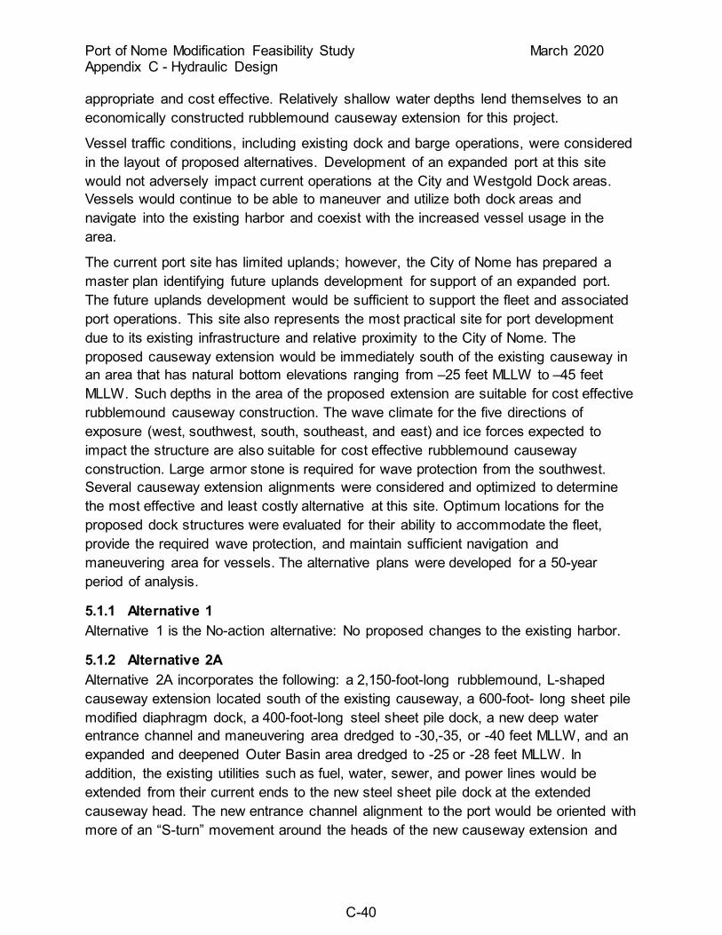
Port of Nome Modification Feasibility Study March 2020 Appendix C - Hydraulic Design
C-40
appropriate and cost effective. Relatively shallow water depths lend themselves to an economically constructed rubblemound causeway extension for this project.
Vessel traffic conditions, including existing dock and barge operations, were considered in the layout of proposed alternatives. Development of an expanded port at this site would not adversely impact current operations at the City and Westgold Dock areas. Vessels would continue to be able to maneuver and utilize both dock areas and navigate into the existing harbor and coexist with the increased vessel usage in the area.
The current port site has limited uplands; however, the City of Nome has prepared a master plan identifying future uplands development for support of an expanded port. The future uplands development would be sufficient to support the fleet and associated port operations. This site also represents the most practical site for port development due to its existing infrastructure and relative proximity to the City of Nome. The proposed causeway extension would be immediately south of the existing causeway in an area that has natural bottom elevations ranging from –25 feet MLLW to –45 feet MLLW. Such depths in the area of the proposed extension are suitable for cost effective rubblemound causeway construction. The wave climate for the five directions of exposure (west, southwest, south, southeast, and east) and ice forces expected to impact the structure are also suitable for cost effective rubblemound causeway construction. Large armor stone is required for wave protection from the southwest. Several causeway extension alignments were considered and optimized to determine the most effective and least costly alternative at this site. Optimum locations for the proposed dock structures were evaluated for their ability to accommodate the fleet, provide the required wave protection, and maintain sufficient navigation and maneuvering area for vessels. The alternative plans were developed for a 50-year period of analysis.
5.1.1 Alternative 1 Alternative 1 is the No-action alternative: No proposed changes to the existing harbor.
5.1.2 Alternative 2A Alternative 2A incorporates the following: a 2,150-foot-long rubblemound, L-shaped causeway extension located south of the existing causeway, a 600-foot- long sheet pile modified diaphragm dock, a 400-foot-long steel sheet pile dock, a new deep water entrance channel and maneuvering area dredged to -30,-35, or -40 feet MLLW, and an expanded and deepened Outer Basin area dredged to -25 or -28 feet MLLW. In addition, the existing utilities such as fuel, water, sewer, and power lines would be extended from their current ends to the new steel sheet pile dock at the extended causeway head. The new entrance channel alignment to the port would be oriented with more of an “S-turn” movement around the heads of the new causeway extension and

Port of Nome Modification Feasibility Study March 2020 Appendix C - Hydraulic Design
C-41
the existing main breakwater and into the inner maneuvering area and navigation channel. This entrance channel configuration is somewhat different from the existing condition but was designed to meet safe navigation criteria under extreme wave and wind conditions. A new navigation marker light would be established at the head of the new causeway extension along with the existing one at the main breakwater head to guide vessels into the port. This alternative was not carried forward for detailed design.
5.1.3 Alternative 2B Alternative 2B includes the same features as Alternative 2A and includes a second sheet pile modified diaphragm dock (450 feet long) located on the inside north-south perimeter of the causeway extension. This alternative was not carried forward for detailed design.
5.1.4 Alternative 3A Alternative 3A includes the same features as Alternative 2B and includes a 450 foot-long realigned main breakwater head that allows for the Outer Basin entrance channel to be widened to 650 feet in width. This alternative includes two additional deep water docks and one Outer Basin dock. This alternative was carried forward for detailed design.
5.1.5 Alternative 3B Alternative 3B includes similar features as Alternative 3A without the 400-foot-long steel sheet pile modified diaphragm dock located on the existing east causeway. This variation of alternative 3A was added to explore the incremental benefits of an alternative with two deep water docks. This alternative was carried forward for detailed design.
5.1.6 Alternative 3C Alternative 3C includes similar features as Alternative 3A without the 400-foot-long steel sheet pile modified diaphragm dock located on the existing east causeway or the 450-foot long steel sheet pile dock located on the inside north-south perimeter of the east causeway extension. This variation of alternative 3A was added to explore the incremental benefits of an alternative with only a single deep water dock. This alternative was carried forward for detailed design.
5.1.7 Alternative 4A Alternative 4A includes the same features as Alternative 2B and includes a new east causeway/breakwater that replaces the existing breakwater and an enlarged Outer Basin area. The new east causeway/breakwater is a straight extension from shore and includes two 400-foot-long steel sheet pile modified diaphragm docks. The combined length of the new east causeway/breakwater is 2,990 linear feet. The alignment of the new east causeway/breakwater also allows for the Outer Basin entrance channel to be

Port of Nome Modification Feasibility Study March 2020 Appendix C - Hydraulic Design
C-42
widened to 900 feet. This alternative includes two additional Deep Water docks and three Outer Basin docks. This alternative was carried forward for detailed design.
5.1.8 Alternative 4B Alternative 4B includes the same features as Alternative 4A and includes a new small boat harbor along the shoreward end of the new west causeway. This alternative includes two additional Deep Water docks and three Outer Basin docks. This alternative was not carried forward for detailed design.
5.1.9 Alternative 5 Alternative 5 would remove the existing breakwater and replace it with a 4,000 linear foot rubblemound breakwater that is aligned with F Street. The Outer Basin would be expanded and deepened to -35 feet MLLW. The new -35 foot MLLW Outer Basin entrance channel would have a channel width of 450 feet. This alternative does not provide a Deep Water Basin or include any additional docks. This alternative was not carried forward for detailed design.
5.1.10 Alternative 6 Alternative 6 would remove the dog-leg portion of the existing breakwater and replace it with a 1,800 linear feet of rubblemound breakwater that is aligned with the shoreward portion of the existing breakwater. The alternative would add an offshore breakwater 3,200 linear feet in length that would give the harbor both an east and a west entrance channel. The Outer Basin would be expanded and deepened to -35 feet MLLW. The new -35 foot MLLW Outer Basin entrance channel would have a channel width of 700 feet. This alternative does not provide a Deep Water Basin or include any additional docks. This alternative was not carried forward for detailed design.
5.1.11 Alternative 7A Alternative 7A includes the removal the existing spur breakwater, a 2,900 foot-long straight extension of the existing rubblemound west causeway, and a new 300 foot-long spur breakwater. The causeway extension would include a 600-foot-long steel sheet pile modified diaphragm dock in water approximately -40 feet MLLW minimizing the new for significant Deep Water Basin dredging. This alternative would only provide a single Deep Water dock and would not modify the existing Outer Basin entrance channel width of 400 feet. This alternative was not carried forward for detailed design.
5.1.12 Alternative 7B Alternative 7B would be similar to that of Alternative 7A and provide a 600-foot-long steel sheet pile modified diaphragm dock and a 450-foot-long steel sheet pile dock located on an L-shaped causeway extension in water approximately -40 feet MLLW minimizing the need for significant Deep Water Basin dredging. The causeway extension would be 4,100 linear foot-long. This alternative would only provide two Deep

Port of Nome Modification Feasibility Study March 2020 Appendix C - Hydraulic Design
C-43
Water docks and would not modify the existing Outer Basin entrance channel width of 400 feet. This alternative was not carried forward for detailed design.
5.1.13 Alternative 8A Alternative 8A includes removal the existing spur breakwater, a 3,937 foot-long L-shaped rubblemound west causeway extension with a 600-foot-long steel sheet pile modified diaphragm dock and two 450-foot-long steel sheet pile docks, dredged Deep Water Basin with a 700 foot wide entrance channel, removal of the existing breakwater, 3,900 foot-long rubblemound east causeway with a 400 foot-long steel sheet pile modified diaphragm dock, expanded Outer Basin with a 650 foot wide entrance channel, and a 400 foot-long steel sheet pile modified diaphragm dock located on the existing causeway. This alternative would provide three Deep Water docks and two Outer Basin docks. This alternative was carried forward for detailed design.
5.1.14 Alternative 8B Alternative 8B includes the same features as Alternative 8A except that the length of the west causeway extension is 3,484 feet in length. This alternative would provide three Deep Water docks and two Outer Basin docks. This alternative was carried forward for detailed design.
5.2 Wave Heights All the alternatives for the Port of Nome site would provide for improved wave protection for the Outer Basin channel, maneuvering area, docks, and navigation channel into the small boat harbor. The extended causeway was positioned to reduce incident wave heights from the various directions of exposure to acceptable levels. The maximum wave heights in the maneuvering areas, based on the 50-year design incident waves from three directions (southwest, south, and southeast), were estimated to be reduced by greater than 50 percent in the Outer Basin using diffraction analysis. Progressively smaller wave heights would occur farther into the inner maneuvering area. Southwest wave heights in the Outer Basin would be reduced approximately 70 percent, approximately 60 percent reduction for waves from the south, and approximately 50 percent reduction for waves from the southeast. The Deep Water Basin area is not intended to be fully protected from incident wave exposure; however, it would provide for partial protection sufficient to support the proposed port operations at the new docks. The southwest wave is the most severe in terms of wave height, period, and frequency of occurrence and the extended causeway head would protect the new docks from wave induced forces.
5.3 Circulation None of the alternatives would restrict circulation flows into the enclosed Outer Basin because the proposed causeway extension would be outside and offset from the existing navigation channel. It is estimated that the exchange of water in the new

Port of Nome Modification Feasibility Study March 2020 Appendix C - Hydraulic Design
C-44
configurations would be similar to that of the existing port during each tide cycle. Because the tide range at Nome is relatively minimal, water exchange due to tidal influence is minor. Wind induced currents and flow from the Snake River are estimated to provide the larger portion of water exchange within the port system. Also, the breaches in the causeways/breakwaters provide flow paths for wave driven currents and rip currents.
5.4 Shoaling Significant shoaling of the new entrance channels would not be expected since there has historically been little maintenance dredging in the existing entrance channel. The tip shoal that has been building at the head of the existing causeway has so far not encroached to the east and impacted the navigation channel. It has, however, been a concern. The new causeway extension would provide additional length and orientation that would be expected to further minimize the concern of shoaling in the entrance. In addition, as the buildup of sediments on the beach west of the causeway at the bridge is worked through the system in conjunction with the existing east sediment trap and maintenance dredging, it is estimated that shoaling in the entrance channel would be minimal over the life of the project. Shoaling at the existing Nome harbor currently requires annual maintenance dredging. Dredge quantities in the current Outer Basin are small and usually changes depths by less than a foot annually in the Outer Basin.
5.5 Construction Dredging Dredging would be required for the Nome alternatives. Dredging quantities and conditions were derived from the most current bathymetry and geotechnical data available. The dredged material would consist of silts, sands, gravel, cobbles, boulders, and glacial till. It is anticipated that dredging such material would be difficult but could be performed with mechanical equipment such as a clam shell dredge and would not require drilling and blasting. Construction dredging quantities for the Port of Nome alternatives are shown in Table 13. Side slopes for the entrance channel and maneuvering area would be dredged to lV:3H. Side slopes would not require slope protection. The quantities presented below reflect the dredge quantities to the maxpay depth for each basin.

Port of Nome Modification Feasibility Study March 2020 Appendix C - Hydraulic Design
C-45
Table 13: Construction dredging quantities for Port of Nome Alternatives
Port of Nome Alternative
Outer Basin -28 ft MLLW
(cubic yards)
Deep Water Basin -40 ft MLLW
(cubic yards) 3A 461,000 997,000 4 799,000 997,000 8A 2,016,000 475,000 8B 2,016,000 518,000
5.6 Dredged Material Disposal Currently, a dredge material disposal site has not been identified for the construction dredging of the harbor modifications. Several possibilities dredge material disposal sites are:
A previously permitted offshore dredged material disposal area is located just southeast of the proposed project in water depths ranging from -25 to -50 feet MLLW. This site was used historically for disposal of maintenance dredged material from the small boat harbor and most recently the material from the Navigation Improvements project in 2005. Dredged material could be disposed of by dump scow barge efficiently using this site. Alternatively, a new offshore disposal site could be designated in deeper water, for example at depths of approximately -50 feet MLLW, to the south of the proposed project. Dredged material could be disposed of by dump scow barge in such a location.
Currently, the maintenance dredged material from the existing channel and harbor at Nome is placed in the near shore area along the beach. This area is approximately 0.5 miles east of the existing main breakwater in front of the existing rock seawall extension west of Front Street. The dredged material for the proposed project could be placed east of this site for purposes of further nourishing the beach in front of and to the east of Nome. Water depths vary from approximately 0 feet MLLW at the beach to -30 feet MLLW offshore. Dredged materials could be placed in the littoral zone in an evenly distributed manner parallel to the beach line progressing in the easterly direction.
Additionally, several possible upland areas within the City of Nome could be used for placement of dredged material for use as fill for site development. Further evaluation of the material within the proposed dredge prism would be required to determine if the material would be suitable for purposes of construction as fill.
5.7 Maintenance Dredging Annual maintenance dredging is expected over the course of the design life of the project. The first maintenance dredging of the existing -22-foot MLLW area occurred in 2014, 8 years after its initial construction in 2006. Annual maintenance dredging has been performed every year since 2006. Littoral transport of sediments generally appears to be from west to east under the bridge and into the east sediment trap. The

Port of Nome Modification Feasibility Study March 2020 Appendix C - Hydraulic Design
C-46
inner harbor entrance channel through the sand spit appears to capture material not deposited in the east sediment trap where it is maintenance dredged annually.
5.8 Causeway and Main Breakwater Extension Design The positioning of the new causeway extension would create an entrance channel alignment allowing access to the port from the southeast. Maximum depths of water are –46 feet MLLW along the alignment of the causeway extension at the head. Foundation materials would be sand, gravel, and glacial till that would serve as a suitable base for the structure. The existing spur breakwater would be demolished and the causeway head would be removed for tie-in of the new causeway extension.
Methods described in the CEM using Hudson’s equation were used to determine armor stone sizes for the new causeway extension, essentially using the same design as the existing causeway by TAMS. Stone size for the outer armor layer was determined using the significant wave height established previously, along with a sea-side side slope of 2H:1V and harbor-side slope of 1.5H:1V, and a Kd value of 12 for selective placement and a breaking wave condition. A stone specific gravity of 2.65 was assumed for the calculations. Armor stone (A1 rock) with a range of sizes from 27-ton maximum weight, 22-ton average weight to 19-ton minimum weight would be used on the seaward face of the causeway extension. Secondary stone (B2 rock) would range from 7,500-pound maximum weight, 4,000-pound average weight to 3,000-pound minimum weight. Core stone (C1 rock) would range from 1,000-pound maximum weight, 300-pound average weight to 150-pound minimum weight. Filter stone (D rock) would be well graded gravel with a gradation of maximum 5 percent greater than 6 inches, and maximum of 15 percent passing the ¾-inch sieve. Sea-side armor stone thickness would be 15 feet, and secondary stone thickness would be 7 feet. For the harbor side, armor stone (A5 rock) with a range of sizes from 10-ton maximum weight, 8-ton average weight to 6-ton minimum weight would be used on the inside face of the causeway extension. Secondary stone (B3 rock) would range from 3,600-pound maximum weight, 1,600-pound average weight to 1,000-pound minimum weight. Core stone (C2 rock) would range from 150-pound maximum weight, 80-pound average weight to 15-pound minimum weight. “F” fill material would be classified fill 3-inch maximum and non-frost-susceptible. “E” fill material would be unclassified fill and could be derived from the various gold dredge tailings sites in Nome. All the armor stone would be placed “selectively” with the long axis of each stone oriented perpendicular to the side slope and with maximum contact with each surrounding stone. The A1 rock would extend down the sea-side slope to a 6-foot dredged-in B2 rock buttress configuration at the base of the causeway extension. This provides for toe stability by anchoring the lower reaches of the side slope into the in-situ seafloor material and provides protection from potential scour. The A5 rock is sized to be stable under moving ice pack and ice run-up conditions.

Port of Nome Modification Feasibility Study March 2020 Appendix C - Hydraulic Design
C-47
The crest elevation for the sea side of the causeway extension was set to +28.5 feet MLLW, similar to the 28 foot MLLW crest of the existing causeway. It was determined by considering wave run-up, storm surge, sealevel change, and extreme high tides to provide for a non-overtopping structure. Projected sea level rise was originally not taken into account during the initial design of the causeway but has since been evaluated and incorporated into this feasibility study. For the harbor side of the causeway extension, the crest elevation was set at +16.5 feet MLLW. A roadway driving surface width of 30 feet was selected for vehicle access to the proposed docks.
For all three Alternative 3 variations, the existing main breakwater head for a distance of approximately 450 linear feet would be demolished and re-positioned on a more easterly dog-legged alignment. This would be necessary to provide for additional entrance channel width. Stone size for the outer armor layer of the re-aligned breakwater head was determined based on using the same size armor stone (A5) as the existing seaward side of the trunk section of the main breakwater. Since the proposed causeway extension would provide for full wave protection from the southwest and south, the armor stone size requirement for the new main breakwater head would be governed by ice forces instead of wave forces. Therefore, a “transition” section similar to the existing main breakwater head would be used for the re-aligned head with A5 and A6 armor stone transitioning to all A5 armor stone. As established previously, the side slopes of 1.5H:1V would transition to 2H:1V over a distance of 100 linear feet. Armor stone (A5 rock) with a range of sizes from 10-ton maximum weight, 8-ton average weight to 6-ton minimum weight would be used on the seaward face of the transition and full head section of the main breakwater. A6 rock with a range of sizes from 6.5-ton maximum weight, 5-ton average weight to 4-ton minimum weight would be used on the harbor side face of the transition section of the main breakwater. Sea-side armor stone thickness would be 10 feet, and secondary stone thickness would be 5 feet. For the transition section harbor side, armor stone (A6 rock) layer thickness would be 9 feet. All the armor stone would be placed “selectively” with the long axis of each stone oriented perpendicular to the side slope and with maximum contact with each surrounding stone. The A5 rock would extend down the side slopes to a 5-foot dredged-in B3 rock buttress configuration at the base of the main breakwater realignment. This provides for toe stability by anchoring the lower reaches of the side slope into the in-situ seafloor material and provides protection from potential scour. The A5 rock is sized to be stable under moving ice pack and ice run-up conditions.
Typical sections for the causeway extension and main breakwater modifications are shown in the Attachments Section of this appendix.
5.9 Concrete Caisson Dock Design Proposed docks within the new Deep Water Basin could be constructed of concrete caission dock modules. The proposed concrete caisson docks were designed based on
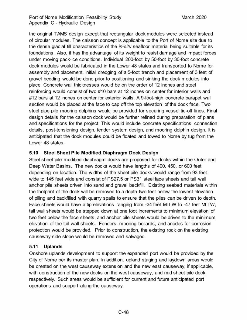
Port of Nome Modification Feasibility Study March 2020 Appendix C - Hydraulic Design
C-48
the original TAMS design except that rectangular dock modules were selected instead of circular modules. The caisson concept is applicable to the Port of Nome site due to the dense glacial till characteristics of the in-situ seafloor material being suitable for its foundations. Also, it has the advantage of its weight to resist damage and impact forces under moving pack-ice conditions. Individual 200-foot by 50-foot by 30-foot concrete dock modules would be fabricated in the Lower 48 states and transported to Nome for assembly and placement. Initial dredging of a 5-foot trench and placement of 3 feet of gravel bedding would be done prior to positioning and sinking the dock modules into place. Concrete wall thicknesses would be on the order of 12 inches and steel reinforcing would consist of two #10 bars at 12 inches on center for interior walls and #12 bars at 12 inches on center for exterior walls. A 9-foot-high concrete parapet wall section would be placed at the face to cap off the top elevation of the dock face. Two steel pipe pile mooring dolphins would be provided for securing vessel tie-off lines. Final design details for the caisson dock would be further refined during preparation of plans and specifications for the project. This would include concrete specifications, connection details, post-tensioning design, fender system design, and mooring dolphin design. It is anticipated that the dock modules could be floated and towed to Nome by tug from the Lower 48 states.
5.10 Steel Sheet Pile Modified Diaphragm Dock Design Steel sheet pile modified diaphragm docks are proposed for docks within the Outer and Deep Water Basins. The new docks would have lengths of 400, 450, or 600 feet depending on location. The widths of the sheet pile docks would range from 93 feet wide to 145 feet wide and consist of PS27.5 or PS31 steel face sheets and tail wall anchor pile sheets driven into sand and gravel backfill. Existing seabed materials within the footprint of the dock will be removed to a depth two feet below the lowest elevation of piling and backfilled with quarry spalls to ensure that the piles can be driven to depth. Face sheets would have a tip elevations ranging from -34 feet MLLW to -47 feet MLLW, tail wall sheets would be stepped down at one foot increments to minimum elevation of two feet below the face sheets, and anchor pile sheets would be driven to the minimum elevation of the tail wall sheets. Fenders, mooring bollards, and anodes for corrosion protection would be provided. Prior to construction, the existing rock on the existing causeway side slope would be removed and salvaged.
5.11 Uplands Onshore uplands development to support the expanded port would be provided by the City of Nome per its master plan. In addition, upland staging and laydown areas would be created on the west causeway extension and the new east causeway, if applicable, with construction of the new docks on the west causeway, and mid sheet pile dock, respectively. Such areas would be sufficient for current and future anticipated port operations and support along the causeway.

Port of Nome Modification Feasibility Study March 2020 Appendix C - Hydraulic Design
C-49
5.12 Entrance Channel Navigation All the proposed causeway extension alignments would create a deep water entrance channel with an effective width of 700 feet at project depth east of the new causeway head. This width was established to provide for the design vessel (tanker) or the USCG icebreaker to maneuver into position at the new dock. It would also allow new and existing barge, tug, and support vessel traffic to enter the outer maneuvering area with protection from southwesterly and southerly wave conditions. Sufficient width and turning radius is provided for the right angle right turn into the Outer Basin area. In addition, the effective channel into the Outer Basin area is increased to a width of 650 feet due to the removal of the spur breakwater. For alternatives with modifications to the east breakwater or a new east causeway the width of the channel into the Outer Basin maneuvering area was widened to 650 feet or greater to accommodate sufficient clearance for the larger, deeper draft vessels to navigate to the new Outer Basin docks.
6.0 PROJECT IMPLEMENTATION
6.1 Breakwaters and Causeways Breakwater and causeway construction would typically be performed under a USACE administered contract to ensure that minimum construction requirements are met as the port alternatives are built. The breakwater and causeways would use several layers of stone armor to achieve wave protection and filtering criteria. All material used in the construction of these project features would be of a self-compacting nature consisting of rock spalls or dredged tailings that can be placed underwater by excavator bucket, skip box, or dump scow. Fill prisms and “C” rock layers would be randomly placed and controlled by construction survey to assure that design elevations and layer thicknesses were met. Larger stone, typically “B” rock and “A” rock layers would be placed selectively by an excavator with an articulated thumb or crane with rock tongs to achieve minimum stone to stone contact requirements. Placement of stone would likely be performed by equipment mounted on a barge. Where road access is provided by the causeways, stone placement could be accomplished from dry ground; however, this may be limited by the reach of the placing equipment.
6.2 Dredging The construction dredging is assumed to require mechanical dredging equipment to reach design depths due to the amount of cobbles and boulders expected within the dredge material. Dredging would most likely employ the use of cranes with clamshell buckets or excavators mounted on barges. The dredge machinery would load a scow, which would deliver the dredged material to a nearshore placement area or an offshore disposal site. Multiple scows may be used to provide for continuous dredging operations. Dredging of finer sediments at Nome may employ either a cutter head or

Port of Nome Modification Feasibility Study March 2020 Appendix C - Hydraulic Design
C-50
clamshell with materials being disposed of onshore through direct placement or in the nearshore environment inside of the zone of closure to ensure materials are pushed to the beach through wave action.
6.3 Modified Diaphragm Sheet Pile Dock Prior to construction of a modified diaphragm sheet pile dock the seaward portions of the causeway would have to be constructed to provide wave protection and retain dock fill material to be placed after pile driving. Prior to pile driving the area within ten feet of the dock footprint would be excavated to remove any cobbles and boulders that would prevent pile driving. The depth of excavation would extend two feet below the lowest depth of pile driving. The excavation would be backfilled to the maximum dredge depth with E fill material. Pile driving could then be accomplished using impact or vibratory hammers, but it is expected to be accomplished with vibratory equipment. After completion of the pile driving operation the dock fill material could would be placed to design elevation and tie the dock to the partially completed causeway. The harbor side of the causeway stone and fill placement could then be finished in the vicinity of the dock.
6.4 Caisson Dock The caisson dock design was initially consider for this project, however all the docks designed for this project are now based on the modified diaphragm sheet pile dock construction method discussed in Section 6.3. Although no longer considered for this project the implementation discussion is presented here to show that this design was once considered.
The caisson dock represents a specialized construction activity with two distinct phases: caisson fabrication and caisson placement. The fabrication phase would occur outside Alaska, presumably on the west coast of the United States in a controlled precast fabrication facility. Fabrication may occur in a precast fabricator’s graving yard or leased dry dock space with concrete production equipment temporarily moved to the facility to cast the caissons. Production of the caissons would potentially take an entire calendar year due to the height of the caissons, tonnage of reinforcing bars to be assembled and placed, and the volume of concrete to be poured. Once completed, the caissons would be floated from the production facilities and towed to the site by tug or placed on a submersible heavy lift barge and towed to the site. The caissons would be fitted with precast concrete lids to prevent water from filling the units and lowering their draft in transit. The tow or barging operation would be timed to occur in the summer months to minimize the chance of heavy seas in the Gulf of Alaska and minimize the risk of damaging or losing the caissons in transit.
Prior to arrival, the dock locations would need to be dredged to 3 feet below the bottom of the caisson and filled with a level bedding course of rock spalls or aggregate material
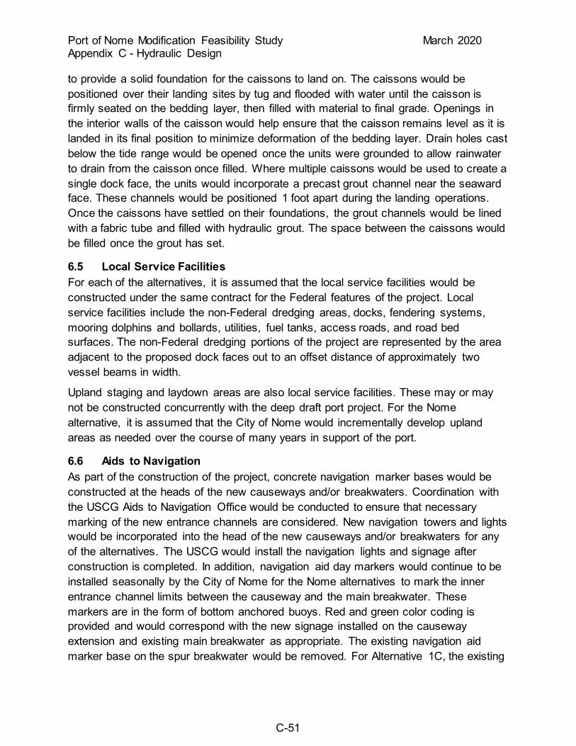
Port of Nome Modification Feasibility Study March 2020 Appendix C - Hydraulic Design
C-51
to provide a solid foundation for the caissons to land on. The caissons would be positioned over their landing sites by tug and flooded with water until the caisson is firmly seated on the bedding layer, then filled with material to final grade. Openings in the interior walls of the caisson would help ensure that the caisson remains level as it is landed in its final position to minimize deformation of the bedding layer. Drain holes cast below the tide range would be opened once the units were grounded to allow rainwater to drain from the caisson once filled. Where multiple caissons would be used to create a single dock face, the units would incorporate a precast grout channel near the seaward face. These channels would be positioned 1 foot apart during the landing operations. Once the caissons have settled on their foundations, the grout channels would be lined with a fabric tube and filled with hydraulic grout. The space between the caissons would be filled once the grout has set.
6.5 Local Service Facilities For each of the alternatives, it is assumed that the local service facilities would be constructed under the same contract for the Federal features of the project. Local service facilities include the non-Federal dredging areas, docks, fendering systems, mooring dolphins and bollards, utilities, fuel tanks, access roads, and road bed surfaces. The non-Federal dredging portions of the project are represented by the area adjacent to the proposed dock faces out to an offset distance of approximately two vessel beams in width.
Upland staging and laydown areas are also local service facilities. These may or may not be constructed concurrently with the deep draft port project. For the Nome alternative, it is assumed that the City of Nome would incrementally develop upland areas as needed over the course of many years in support of the port.
6.6 Aids to Navigation As part of the construction of the project, concrete navigation marker bases would be constructed at the heads of the new causeways and/or breakwaters. Coordination with the USCG Aids to Navigation Office would be conducted to ensure that necessary marking of the new entrance channels are considered. New navigation towers and lights would be incorporated into the head of the new causeways and/or breakwaters for any of the alternatives. The USCG would install the navigation lights and signage after construction is completed. In addition, navigation aid day markers would continue to be installed seasonally by the City of Nome for the Nome alternatives to mark the inner entrance channel limits between the causeway and the main breakwater. These markers are in the form of bottom anchored buoys. Red and green color coding is provided and would correspond with the new signage installed on the causeway extension and existing main breakwater as appropriate. The existing navigation aid marker base on the spur breakwater would be removed. For Alternative 1C, the existing

Port of Nome Modification Feasibility Study March 2020 Appendix C - Hydraulic Design
C-52
navigation marker base would be repositioned on the re-aligned main breakwater head. The existing range boards and lights located on-shore would likely remain with some possible modifications in elevation to guide navigation in the inner channel/maneuvering area.
6.7 Construction Schedule Major construction features for the recommended plan (Alternative 8B) include the rubble-mound west causeway extension, new rubble-mound east causeway, spur breakwater demolition, main breakwater demolition, dredging, sheet pile docks, and extension of fuel, water, and power lines. Stone production in the quarry, dock footprint dredging and backfill, and causeway toe dredging would likely be the first features undertaken. Partial construction of the causeways would likely take place next to provide wave protection for the sheet pile dock construction and dredging. Concurrent demolition of the existing spur breakwater and main breakwater head would likely take place with the salvaged armor stone incorporated into the new construction. Work on dredging and dredge material placement/disposal would then follow. Sheet pile dock construction could begin following partial completion of the causeways and completion. Completion of the causeway harbor-side placement would take place after the sheet pile dock construction. Extension of fuel, water, and power lines would likely take place throughout causeway and dock construction.
The use of the existing City, Middle, and Westgold docks would need to be maintained during any construction season. Construction scheduling would be required to avoid conflict with the continued use of the existing port and harbor facilities at Nome. The existing dock facilities, causeway access road, fuel lines, water lines, power, navigation channel, and small boat harbor would remain operational during construction. Project specifications would detail time restrictions for the contractor to conduct certain activities during specified time periods.
The estimated performance period for construction is a minimum of 4 years with a likely construction duration of 5 to 6 years. The duration of each summer construction season is estimated to be five and a half months (mid-May through October). Winter construction is not anticipated.

Port of Nome Modification Feasibility Study March 2020 Appendix C - Hydraulic Design
C-53
7.0 OPERATIONS AND MAINTENANCE The non-Federal operator of the Port would be responsible for operation and maintenance of the completed mooring areas and local service facilities portion of the project. The Federal Government would be responsible for maintenance of the causeway extension and breakwaters (except for the road prism and surfaces, and docks and other local service facilities) and the entrance channel portions of the project. The Alaska District, U.S. Army Corps of Engineers would visit the site(s) periodically to inspect the causeways and breakwaters and perform annual hydrographic surveys of the entrance channels and basins as part of the regular maintenance dredging contracts. The hydrographic surveys would be used to determine maintenance dredging needs for the entrance channel and maneuvering basin areas. Maintenance requirements for the causeways and breakwaters would be determined from the surveys and inspections. Local and Federal dredging requirements, if necessary, will likely be combined, to save the costs associated with multiple mobilizations and demobilizations.
The causeways and breakwaters for the recommended plan were designed to be stable for the 50-year predicted wave conditions. Therefore, no significant loss of stone from the rubblemound structures is expected over the life of the project. It is estimated that at the worst case, 2.5 percent of the armor stone would need to be replaced every 25 years. Because stone quality would be strictly specified in the project construction contracts, little to no armor stone degradation would be anticipated.
Maintenance dredging for the recommended plan would be conducted annually. The Outer Basin and channel areas would require annual dredging of approximately 88,000 cubic yards. The Deep Water Basin and channel areas at -40ft MLLW would require annual dredging of approximately 16,000 cubic yards. A dredged material management plan would be developed for the project in which a long-term disposal option would be identified. For purposes of this study, it is assumed that the outer channel and maneuvering area material would be disposed of in the offshore disposal area east of the port. For the expanded inner maneuvering area, the material would likely be placed on the beach east of the main breakwater as is the current dredged material from the navigation improvements project. Hydraulic cutter head dredging equipment with pipe-line discharge would likely be used for maintenance dredging. Dredged material characteristics should be similar to the current material dredged from the existing navigation channel and sediment trap: sand.
The modified diaphragm steel sheet pile docks would require replacing anodes on an estimated 15-year cycle. For the mooring dolphins, the anodes would be replaced on an estimated 15-year cycle. The concrete caisson dock structure(s), if used, would require maintenance on an estimated 20-year cycle. Repairs would include patching damaged concrete surfaces with epoxy grout and grout injection for internal areas.

Port of Nome Modification Feasibility Study March 2020 Appendix C - Hydraulic Design
C-54
8.0 RECOMMENDED FURTHER DESIGN STUDIES The preconstruction engineering design (PED) of the project will include a more thorough analysis of the recommended. Engineering analysis will be performed to support a complete design documentation report. The following are items that will be addressed in the PED phase of the project:
a. Additional ship simulation studies to optimize entrance channel width, maneuvering area turning requirements, assist tug requirements, and limiting operability conditions.
b. Geotechnical investigation and analysis of subsurface materials at the site to determine their physical characteristics and chemical composition, dredging methods and equipment requirements, and suitability as foundation materials for the proposed causeways, breakwaters, docks, and upland facilities.
c. Detailed design of local service facilities including the proposed docks, fender systems, mooring dolphins and bollards, utilities, access roads, uplands staging and laydown areas, fuel storage, sewage treatment, water supply and treatment, solid waste, and crew facilities.
d. A thorough analysis of harbor response to wind and wave conditions. This analysis includes description of wind and wave climatic conditions at Nome, some of which is contained in this appendix, wave transformation analysis to show how wave energy propagates through the harbor and any necessary supporting numerical model studies such as STWave modeling to show harbor performance.
e. An analysis of the wave conditions within the entrance channel mooring basins was not performed due to budget and schedule restrictions. Physical modeling of selected alternative should be under taken during PED to validate harbor response. Flume studies should be conducted determine runup and ovetopping requirements, and to verify armor stone and capstone sizing and stability.
f. An analysis of wave interaction and beach modifications. Numerical modeling of the local wave climate and near shore circulations using a Boussinesq 2D model should be conducted to determine the beach evolution under the selected alternative and to evaluate construction and O&M maintenance dredge placements.

Port of Nome Modification Feasibility Study March 2020 Appendix C - Hydraulic Design
C-55
9.0 REFERENCES Permanent International Association of Navigation Congresses (PIANC), 1995. “Criteria for Movements of Moored Ships in Harbours, a Practical Guide, Report of the Working Group no. 24 of the Permanent Technical Committee II, Supplement to Bulletin No. 88”.
Tippetts, Abbett, McCarthy, Stratton (TAMS) Engineers, 1982. “Port of Nome, Alaska, Design Memorandum”.
U.S. Army Corps of Engineers (USACE). 2008. “Coastal Engineering Manual” - Part II. Engineer Manual EM 1110-2-1100.
USACE. 1970. “On the Structure of Pressured Sea Ice,” Cold Regions Research and Engineering Laboratory (CRREL) report to the U.S. Coast Guard.
USACE. 1998. “Navigation Improvements Final Interim Feasibility Report, Nome, Alaska” – Appendix A Hydraulic Design.
USACE. 2006. “Hydraulic Design of Deep-Draft Navigation projects,” Engineer Manual (EM) 1110-2-1613.
USACE. 1984. “Hydraulic Design of Small Boat Harbors,” Engineer Manual (EM) 1110-2-
1615. USACE. 1987. “Environmental Engineering for Deep-Draft Navigation Projects,” Engineer
Manual (EM) 1110-2-1202. USACE. 1986. “Engineering and Design, Design of Breakwaters and Jetties,” Engineer
Manual EM 1110-2-2904. USACE. 1989. “Water Levels and Wave Heights for Coastal Engineering Design,”
Engineer Manual EM 1110-2-1414. USACE. 2013. “Incorporating Sea Level Change in Civil Works Programs,” Engineer
Regulation ER 1100-2-8162. USACE. 1998. “Design for Navigation Improvements at Nome Harbor, Alaska, Coastal
Model Investigation” - Technical Report CHL-98-28. USACE. 2009. “Storm-Induced Water Level Prediction Study for the Western Coast of
Alaska,” ERDC/CHL Letter Report. USACE. 1984. “Shore Protection Manual,” Fourth Ed.
Port of Nome Modification Feasibility Study March 2020 Appendix C - Hydraulic Design
C-56
USGS. 2003. “Estimating the Magnitude and Frequency of Peak Streamflows for Ungaged Sites on Streams in Alaska and Conterminous Basins in Canada,” Water-Resources Investigation Report 03-4188.
Thor, D. R. and Nelson, C. H.. 1980. “Ice Gouging on the Subarctic Bering Shelf,” in The
Eastern Bering Sea Shelf: Oceanography and Resources (D.W. Hood and J.A. Calder, Eds.). U.S. Department of Commerce, National Oceanic and Atmospheric Administration, Office of Marine Pollution Assessment, Juneau, Alaska, Vol. 1.
C., S. Gray, M. Berman, L. Eerkes-Medrano, T. Hennessy, H. Huntington, J. Littell, M.
McCammon, R. Thoman, and S. Trainor, 2018: Alaska. In Impacts, Risks, and Adaptation in the United States: Fourth National Climate Assessment, Volume II. U.S. Global Change Research Program, Washington, DC, USA, pp. 1185–1241.

Port of Nome Modification Feasibility Study March 2020 Appendix C - Hydraulic Design
C-57
10.0 ATTACHMENTS


![Hydraulic Design[1]](https://img.pdfslide.net/doc/110x75/5571f96149795991698f72eb/hydraulic-design1.jpg)