Embed Size (px)
Citation preview
GUDMUNDSSON – GENERAL AVIATION AIRCRAFT DESIGN APPENDIX C5 – DESIGN OF UNUSUAL CONFIGURATIONS 1
©2013 Elsevier, Inc. This material may not be copied or distributed without permission from the Publisher.
APPENDIX C5: Design of Unusual Configurations
This appendix is a part of the book General Aviation Aircraft Design: Applied Methods and Procedures by Snorri Gudmundsson, published by Elsevier, Inc. The book is available through various bookstores and online retailers, such as www.elsevier.com, www.amazon.com, and many others. The purpose of the appendices denoted by C1 through C5 is to provide additional information on the design of selected aircraft configurations, beyond what is possible in the main part of Chapter 4, Aircraft Conceptual Layout. Some of the information is intended for the novice engineer, but other is advanced and well beyond what is possible to present in undergraduate design classes. This way, the appendices can serve as a refresher material for the experienced aircraft designer, while introducing new material to the student. Additionally, many helpful design philosophies are presented in the text. Since this appendix is offered online rather than in the actual book, it is possible to revise it regularly and both add to the information and new types of aircraft. The following appendices are offered:
C1 – Design of Conventional Aircraft C2 – Design of Canard Aircraft C3 – Design of Seaplanes C4 – Design of Sailplanes C5 – Design of Unusual Configurations (this appendix)
Figure C5-1: A Marske Pioneer II-D, single seat flying wing in flight (photo courtesy of Jim Marske).
GUDMUNDSSON – GENERAL AVIATION AIRCRAFT DESIGN APPENDIX C5 – DESIGN OF UNUSUAL CONFIGURATIONS 2
©2013 Elsevier, Inc. This material may not be copied or distributed without permission from the Publisher.
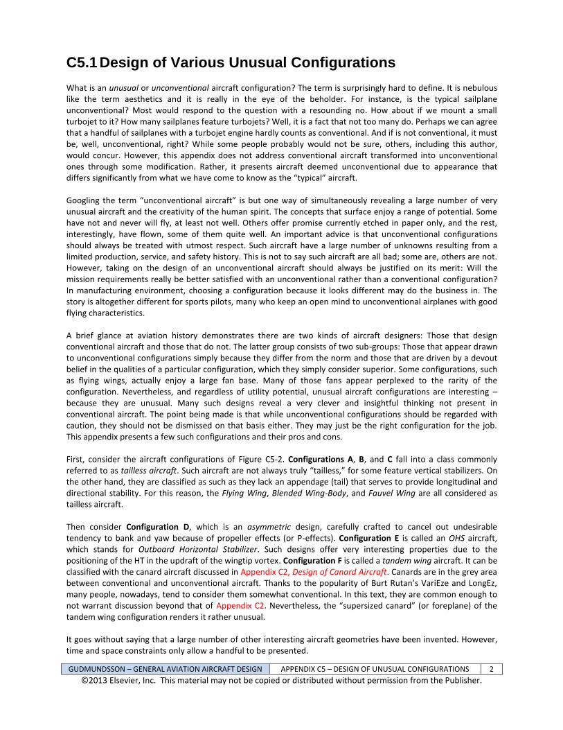
C5.1 Design of Various Unusual Configurations What is an unusual or unconventional aircraft configuration? The term is surprisingly hard to define. It is nebulous like the term aesthetics and it is really in the eye of the beholder. For instance, is the typical sailplane unconventional? Most would respond to the question with a resounding no. How about if we mount a small turbojet to it? How many sailplanes feature turbojets? Well, it is a fact that not too many do. Perhaps we can agree that a handful of sailplanes with a turbojet engine hardly counts as conventional. And if is not conventional, it must be, well, unconventional, right? While some people probably would not be sure, others, including this author, would concur. However, this appendix does not address conventional aircraft transformed into unconventional ones through some modification. Rather, it presents aircraft deemed unconventional due to appearance that differs significantly from what we have come to know as the “typical” aircraft. Googling the term “unconventional aircraft” is but one way of simultaneously revealing a large number of very unusual aircraft and the creativity of the human spirit. The concepts that surface enjoy a range of potential. Some have not and never will fly, at least not well. Others offer promise currently etched in paper only, and the rest, interestingly, have flown, some of them quite well. An important advice is that unconventional configurations should always be treated with utmost respect. Such aircraft have a large number of unknowns resulting from a limited production, service, and safety history. This is not to say such aircraft are all bad; some are, others are not. However, taking on the design of an unconventional aircraft should always be justified on its merit: Will the mission requirements really be better satisfied with an unconventional rather than a conventional configuration? In manufacturing environment, choosing a configuration because it looks different may do the business in. The story is altogether different for sports pilots, many who keep an open mind to unconventional airplanes with good flying characteristics. A brief glance at aviation history demonstrates there are two kinds of aircraft designers: Those that design conventional aircraft and those that do not. The latter group consists of two sub-groups: Those that appear drawn to unconventional configurations simply because they differ from the norm and those that are driven by a devout belief in the qualities of a particular configuration, which they simply consider superior. Some configurations, such as flying wings, actually enjoy a large fan base. Many of those fans appear perplexed to the rarity of the configuration. Nevertheless, and regardless of utility potential, unusual aircraft configurations are interesting – because they are unusual. Many such designs reveal a very clever and insightful thinking not present in conventional aircraft. The point being made is that while unconventional configurations should be regarded with caution, they should not be dismissed on that basis either. They may just be the right configuration for the job. This appendix presents a few such configurations and their pros and cons. First, consider the aircraft configurations of Figure C5-2. Configurations A, B, and C fall into a class commonly referred to as tailless aircraft. Such aircraft are not always truly “tailless,” for some feature vertical stabilizers. On the other hand, they are classified as such as they lack an appendage (tail) that serves to provide longitudinal and directional stability. For this reason, the Flying Wing, Blended Wing-Body, and Fauvel Wing are all considered as tailless aircraft. Then consider Configuration D, which is an asymmetric design, carefully crafted to cancel out undesirable tendency to bank and yaw because of propeller effects (or P-effects). Configuration E is called an OHS aircraft, which stands for Outboard Horizontal Stabilizer. Such designs offer very interesting properties due to the positioning of the HT in the updraft of the wingtip vortex. Configuration F is called a tandem wing aircraft. It can be classified with the canard aircraft discussed in Appendix C2, Design of Canard Aircraft. Canards are in the grey area between conventional and unconventional aircraft. Thanks to the popularity of Burt Rutan’s VariEze and LongEz, many people, nowadays, tend to consider them somewhat conventional. In this text, they are common enough to not warrant discussion beyond that of Appendix C2. Nevertheless, the “supersized canard” (or foreplane) of the tandem wing configuration renders it rather unusual. It goes without saying that a large number of other interesting aircraft geometries have been invented. However, time and space constraints only allow a handful to be presented.
GUDMUNDSSON – GENERAL AVIATION AIRCRAFT DESIGN APPENDIX C5 – DESIGN OF UNUSUAL CONFIGURATIONS 3
©2013 Elsevier, Inc. This material may not be copied or distributed without permission from the Publisher.
Figure C5-2: A flying wing (A), blended wing body (B), a Fauvel flying wing (C), an asymmetric airplane (D), an OHS airplane (E), and a tandem wing airplane (F).
GUDMUNDSSON – GENERAL AVIATION AIRCRAFT DESIGN APPENDIX C5 – DESIGN OF UNUSUAL CONFIGURATIONS 4
©2013 Elsevier, Inc. This material may not be copied or distributed without permission from the Publisher.
C5.1.1 Tailless Aircraft – Flying Wings
Tailless airplanes, of which the flying wing is a prime example, were very popular in the period during and after World War II. The best known flying wings are those designed by John Knudsen "Jack" Northrop (1895-1981), Alexander Martin Lippisch (1894-1976), the Horten brothers, Walter (1913-1998) and Reimar (1915-1994), and Charles Fauvel (1904-1979), all who designed a large number of flying wings. The history of Northrop flying wings is well documented by Pape
1 and that of the Horten brothers by Myhra
2. There are also more recent designers of
small flying wings worth mentioning, for instance Jim Marske (1935-) who has developed a number of flying wings in the style of Fauvel. Renewed interest has been sparked in the concept with the development of the B-2 Spirit stealth bomber, in addition to considerable enthusiasm that has persisted among operators of radio controlled aircraft and kitplanes for a long time. Configuration A of Figure C5-2 shows a typical layout of the flying wing; a clean wing whose fuselage and nacelle is carefully blended into the basic geometry, as well as a complete absence of horizontal and vertical stabilizers. This configuration is the most commonly cited example of tailless aircraft. Due to the similarities between it and the other two styles considered in this class of aircraft (BWB and Fauvel wings are the others), most of the theory of tailless aircraft in this book will be presented here – differences between the flying wing and the others will be addressed on a need-to-basis in the other sections. Pros and Cons of Flying Wings Intuitively, tailless aircraft should be exceptionally efficient. However, experience reveals they are less so than one would think at first glance. There are two notable problems that reduce their effectiveness; the generation of pitch and directional stability. The absence of appendages on which to mount a horizontal or vertical tail brings about substantial challenges in their stability and control and requires clever “tricks of engineering” to resolve. Unfortunately, the cost is increased drag and reduced capability for lift generation. While the absence of a fuselage and other components renders the configuration less draggy than otherwise, the drag is simply greater than it would be if stability did not have to be considered. A case in point is that the most efficient sailplanes are not flying wings, but rather consist of more conventional (relatively speaking) high AR wings mounted on tadpole fuselages with T-tails. Some Open Class competition sailplanes achieve a maximum L/D ratio as high as 70, which is about 2-3 times greater than even the sleekest flying wing. The advantage of using a swept wing planform on a flying wing relates to the fact it provides a longer stabilizing arm. The reason for this will be clarified later. However, as shown in Section 9.5.3, Determination of Lift Curve
Slope, CL, for a 3-D Wing, a swept planform also reduces the wing’s lift curve slope, CL, and this further compounds the reduced effectiveness, as well as dynamic stability characteristics such as pitch damping. The
reduced CL raises the lift-induced drag, further offsetting the potential low drag characteristics of the wing. Swept back wings are subjected to greater dihedral effect – it matters little whether they belong to a conventional aircraft or a flying wing. However, on a flying wing, the dihedral effect is much greater than the directional stability, which is very small. Unless the directional stability is actively increased there would be some Dutch roll or spiral stability issues. The solution to this problem is discussed later in this section. Flying wings often display longitudinal instability near stall. For instance, a Horten style flying wing was tested in the Langley free-flight tunnel in 1945 achieved a CLmax of 1.2 in a force balance test, but was only capable of developing 0.7 in free flight due to poor stability and control at the higher AOA
3. This would have caused an
unacceptably high T-O and landing airspeeds. At first glance, one would expect swept-back flying wings to have dangerous stall characteristics because of the notorious tip-stall tendency associated with the planform. However, in order to stall such airplanes, the elevons must be significantly deflected Trailing Edge Up (TEU). If the elevons are placed near the wingtips, as is usually the case, this brings down section lift coefficients at the tip, promoting a desirable stall progression (from the root to the tip). This should force the inboard wing to stall before the outboard wing, causing the nose to drop in a desirable fashion, while offering roll stability due to the un-stalled wingtip. This tendency is indeed reported by many pilots of flying wings (e.g. see various reports on www.nurflugel.com and the writings of Reimer Horten
4, 5).
GUDMUNDSSON – GENERAL AVIATION AIRCRAFT DESIGN APPENDIX C5 – DESIGN OF UNUSUAL CONFIGURATIONS 5
©2013 Elsevier, Inc. This material may not be copied or distributed without permission from the Publisher.
If the flying wing features a high Aspect Ratio and flexible wing, things may get more complicated, in particular if it features a large Leading Edge (LE) sweep. When nearing stall, at high AOA, the airloads may cause a large aeroelastic wingtip deflection. On an aft swept wing, this may reduce the AOA of the wingtip enough to unload the wing tip, moving the center of lift forward; in the process causing an uncontrollable nose pitch up moment that can drive the aircraft to stall. Such a problem would be compounded for composite wings, which can be very flexible. This phenomenon is referred to as auto-stall. For this reason it is important that high AR, aft swept flying wings are designed with stiff wings to help prevent auto-stall. Since pitch control is usually limited in flying wings, the use of flaps as a high-lift device is rare, albeit possible. A flying wing without high lift devices renders T-O and approach speeds, as well as runway requirements, greater than for conventional configurations. Furthermore, there may be an issue with T-O rotation as the wing tips may strike the ground during rotation, unless a tall enough landing gear is employed. This is remedied by featuring a tall nose landing gear to place the vehicle at an already high AOA during the T-O and landing phases. A summary of selected pros and cons of tailless aircraft is provided by Nickel and Wohlfahrt
6, some of which are
presented in Table C5-1 for convenience. The summary applies to other kinds of tailless aircraft as well. The same cardinal rule applies to the pros and cons of tailless aircraft as that of more conventional aircraft; one should refrain from latching onto a particular one. A flaw does not necessarily mean a great flaw and advantage does not necessarily mean a great advantage. The proper approach is to try and weigh each against each other.
Table C5-1: Summary of Pros and Cons of Tailless Aircraft (partially based on Reference 6)
Advantages Disadvantages
Weak directional stability results in converging spiral stability. This stability makes it easier to maintain constant bank angle when turning.
The weak directional stability may result in an undesirable Dutch roll mode.
Normally, stall behavior is good and tendency to spin is reduced. This is attributed to the reduction in section lift coefficients at the outboard wing, necessitated by the provision of longitudinal stability.
The favorable stall characteristics come at the cost of efficiency, resulting from an increased lift-induced drag due to the longitudinal stability being generated by reduced section lift coefficients on the outboard wing.
The installation of pusher propellers is easier than for conventional aircraft.
The absence of propeller slipstream over a designated vertical tail cannot be used to improve directional stability. Furthermore, the lack of directional stability renders it harder to operate the aircraft in an asymmetric thrust situation.
A low CDmin is to be expected, as a flying inherently has fewer interferences than conventional aircraft.
The reduction in CDmin is shadowed by the increase in CDi, rendering the sleekest flying wing less efficient than the sleekest sailplane. For this reason, performance is often inferior because of the high CDi, which is made even worse when the elevator is deflected. In the interest of evenhandedness, keep in mind that a comparison to sailplane is perhaps not fair. Comparison to conventional powered airplanes would be more reasonable.
Theoretically, a flying wing should be less expensive to build.
Other costs, such as research and development may offset this significantly.
Sweepback will help with longitudinal stability and at the same time is favorable to transonic speeds for high-speed flying wings.
Sweepback also results in greater wing drag, lower lift coefficients, diminished aileron and elevator effectiveness (authority). It increases wing bending oscillations in turbulent weather, which may lead to pitch oscillations. It can also cause “auto-stall” in steep turns and pull-outs, when the sweptback wing deflects up and twists LE down at the same time. This leads to an uncontrolled nose pitch-up, which may stall the craft. Sweepback also requires higher dihedral to give the vehicle wingtip clearance when flaring.
GUDMUNDSSON – GENERAL AVIATION AIRCRAFT DESIGN APPENDIX C5 – DESIGN OF UNUSUAL CONFIGURATIONS 6
©2013 Elsevier, Inc. This material may not be copied or distributed without permission from the Publisher.
Table C5-1, cont’d
Advantages Disadvantages
Tailless aircraft are attractive because of their unconventional looks.
Unconventional looks may be detrimental in the market place because there is less safety and operational history of such airplanes (because they are, well, unconventional – i.e. not common). The market responds by not buying them in the same quantities as conventional aircraft.
A fuselage can be introduced that fairs well into the overall shape of the aircraft.
The introduction of a fuselage (cockpit) decreases stability, rendering the configuration worse than the same geometry without a fuselage. Sometimes, this calls for the introduction of vertical tails at the wingtips. Additionally, it strongly affects the lift over the inboard wing.
The absence of a dedicated tail section reduces drag.
The absence of a tail section requires the flare maneuver (before landing) to be performed using a control surface on the wing itself. The TEU deflection required to flare decreases the effective lift coefficient of the wing, requiring higher landing speeds and longer runway requirements.
No comparative advantage. Small useful CG-envelope reduces the utility potential.
No comparative advantage.
The craft may suffer from adverse yaw when operating ailerons due to the insufficient directional stability and weak rudder authority. The remedy is excessively sized vertical tails, necessitated by the short moment arm.
No comparative advantage. Low pitch damping (Cmq) and moment of inertia about the pitch axis can cause an unacceptable short period oscillation mode (in particular on flying planks) or pilot induced oscillations.
No comparative advantage.
Cross-wind take-offs and landings are harder. This is further compounded by the fact that side-slips do not effectively increase drag like they do on conventional aircraft, to aide in glide path control.
Requirements for Longitudinal Stability As discussed in Chapter 11, The Anatomy of the Tail, the longitudinal stability of any aircraft can be expressed as
the linear relation Cm = Cm0 + Cm∙ (as long as it is operating in mostly attached airflow), referred to as the pitching moment curve. Of course this is the equation of a line. Calling it a curve comes from the fact that once the airflow begins to separate, the line develops into a curve. In this expression, Cm is the pitching moment coefficient and its value must be 0 if the aircraft is “trimmed.” The term Cm0 is the intersection of the Cm curve to the vertical axis of
the Cm - polar (or Cm – CL polar). It must have a positive value in order to trim a statically stable aircraft at a positive lift coefficient (so it can generate lift that opposes its weight). Cm0 is not really a constant because it is controlled by the elevator. And, as shown in Section 11.2.1, Fundamentals of Static Longitudinal Stability, this
controls the trim AOA (denoted by trim). Cm is the slope of the pitching moment curve and, for any longitudinally stable aircraft, must be negative.
The expression for the pitching moment curve (Cm = Cm0 + Cm∙) establishes that in order for any flying wing (or
airplane for that matter) to be stable, the following must hold: (a) Cm < 0 and (b) Cm0 > 0. The former requirement
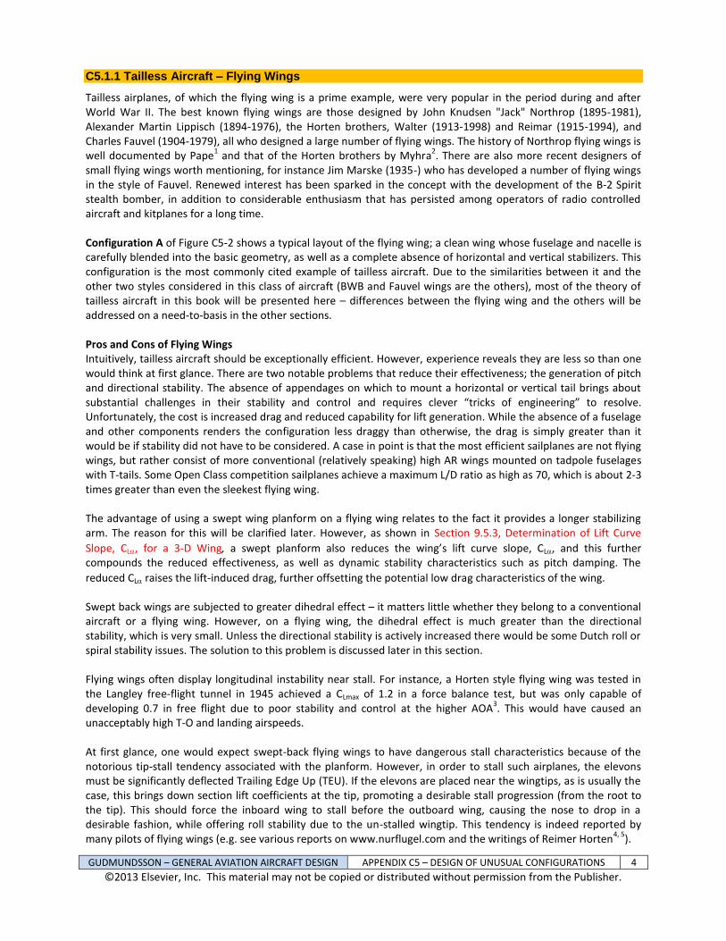
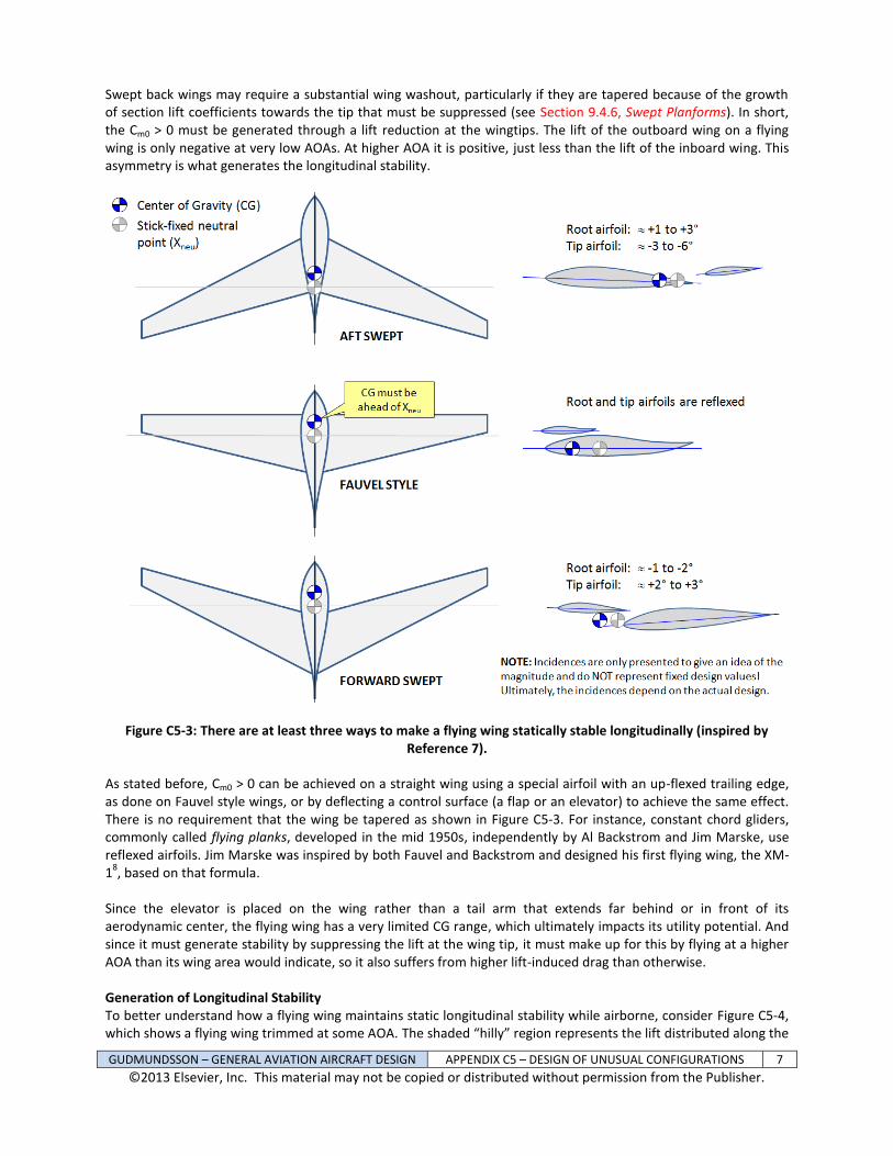
(Cm < 0) is met by ensuring the CG is ahead of the stick-fixed neutral point, just as it is for conventional aircraft. At least three methods are used to achieve the latter requirement (Cm0 > 0) in flying wings and are shown in Figure C5-3:
(1) Swept back wing with a washout (2) Forward swept wings with a washin (3) Straight wings using reflexed airfoils (or reflexed flaps)
GUDMUNDSSON – GENERAL AVIATION AIRCRAFT DESIGN APPENDIX C5 – DESIGN OF UNUSUAL CONFIGURATIONS 7
©2013 Elsevier, Inc. This material may not be copied or distributed without permission from the Publisher.
Swept back wings may require a substantial wing washout, particularly if they are tapered because of the growth of section lift coefficients towards the tip that must be suppressed (see Section 9.4.6, Swept Planforms). In short, the Cm0 > 0 must be generated through a lift reduction at the wingtips. The lift of the outboard wing on a flying wing is only negative at very low AOAs. At higher AOA it is positive, just less than the lift of the inboard wing. This asymmetry is what generates the longitudinal stability.
Figure C5-3: There are at least three ways to make a flying wing statically stable longitudinally (inspired by Reference 7).
As stated before, Cm0 > 0 can be achieved on a straight wing using a special airfoil with an up-flexed trailing edge, as done on Fauvel style wings, or by deflecting a control surface (a flap or an elevator) to achieve the same effect. There is no requirement that the wing be tapered as shown in Figure C5-3. For instance, constant chord gliders, commonly called flying planks, developed in the mid 1950s, independently by Al Backstrom and Jim Marske, use reflexed airfoils. Jim Marske was inspired by both Fauvel and Backstrom and designed his first flying wing, the XM-1
8, based on that formula.
Since the elevator is placed on the wing rather than a tail arm that extends far behind or in front of its aerodynamic center, the flying wing has a very limited CG range, which ultimately impacts its utility potential. And since it must generate stability by suppressing the lift at the wing tip, it must make up for this by flying at a higher AOA than its wing area would indicate, so it also suffers from higher lift-induced drag than otherwise. Generation of Longitudinal Stability To better understand how a flying wing maintains static longitudinal stability while airborne, consider Figure C5-4, which shows a flying wing trimmed at some AOA. The shaded “hilly” region represents the lift distributed along the
GUDMUNDSSON – GENERAL AVIATION AIRCRAFT DESIGN APPENDIX C5 – DESIGN OF UNUSUAL CONFIGURATIONS 8
©2013 Elsevier, Inc. This material may not be copied or distributed without permission from the Publisher.
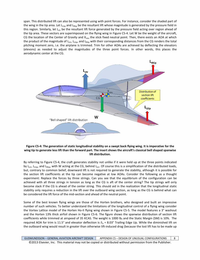
span. This distributed lift can also be represented using with point forces. For instance, consider the shaded part of the wing in the tip area. Let LLtip and LRtip be the resultant lift whose magnitude is generated by the pressure field in this region. Similarly, let Lctr be the resultant lift force generated by the pressure field acting over region ahead of the tip area. These vectors are superimposed on the flying wing in Figure C5-4. Let W be the weight of the aircraft, CG the location of the Center of Gravity and Xneu the stick fixed neutral point. Then, there exists an AOA at which the product of the magnitude of Lctr, LLtip, and LRtip with their corresponding distances from the CG renders the total pitching moment zero, i.e. the airplane is trimmed. Trim for other AOAs are achieved by deflecting the elevators (elevons) as needed to adjust the magnitudes of the three point forces. In other words, this places the aerodynamic center at the CG.
Figure C5-4: The generation of static longitudinal stability on a swept back flying wing. It is imperative for the wing tip to generate less lift than the forward part. The insert shows the aircraft’s classical bell shaped spanwise
lift distribution.
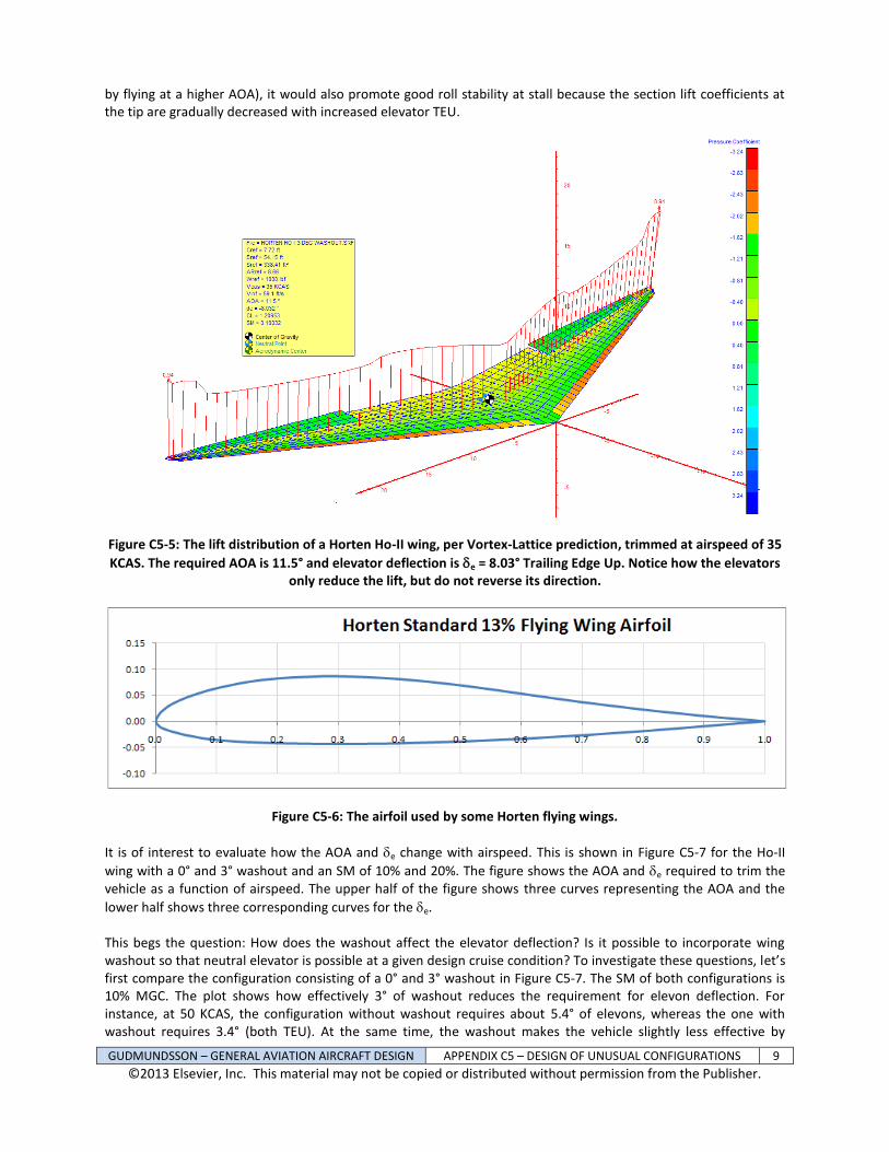
By referring to Figure C5-4, the craft generates stability not unlike if it were held up at the three points indicated by Lctr, LLtip, and LRtip, with W acting at the CG, behind Lctr. Of course this is a simplification of the distributed loads, but, contrary to common belief, downward lift is not required to generate the stability, although it is possible for the section lift coefficients at the tip can become negative at low AOAs. Consider the following as a thought experiment: Replace the forces by three strings. Can you see that the equilibrium of the configuration can be achieved with all three strings in tension as long as the CG is aft of the center string? The tip strings will only become slack if the CG is ahead of the center string. This should aid in the realization that the longitudinal static stability only requires a reduction in the lift over the outboard wing section, as long as the CG is behind what can be considered the lift force of the mid-section and ahead of the neutral point. Some of the best known flying wings are those of the Horten brothers, who designed and built an impressive number of such vehicles. To better understand the limitations of the longitudinal control of a flying wing consider the Vortex Lattice model of the Horten Ho-II flying wing shown in Figure C5-5. The model features a 3° washout and the Horten 13% thick airfoil shown in Figure C5-6. The figure shows the spanwise distribution of section lift coefficients while trimmed at airspeed of 35 KCAS. The weight is 1000 lbf and the Static Margin (SM) is 10%. The
required AOA for trim is 11.5° and elevator deflection is e = 8.03° Trailing Edge Up. While the diminished lift on the outboard wing would result in greater than otherwise lift-induced drag (because the lost lift has to be made up
GUDMUNDSSON – GENERAL AVIATION AIRCRAFT DESIGN APPENDIX C5 – DESIGN OF UNUSUAL CONFIGURATIONS 9
©2013 Elsevier, Inc. This material may not be copied or distributed without permission from the Publisher.
by flying at a higher AOA), it would also promote good roll stability at stall because the section lift coefficients at the tip are gradually decreased with increased elevator TEU.
Figure C5-5: The lift distribution of a Horten Ho-II wing, per Vortex-Lattice prediction, trimmed at airspeed of 35
KCAS. The required AOA is 11.5° and elevator deflection is e = 8.03° Trailing Edge Up. Notice how the elevators only reduce the lift, but do not reverse its direction.
Figure C5-6: The airfoil used by some Horten flying wings.
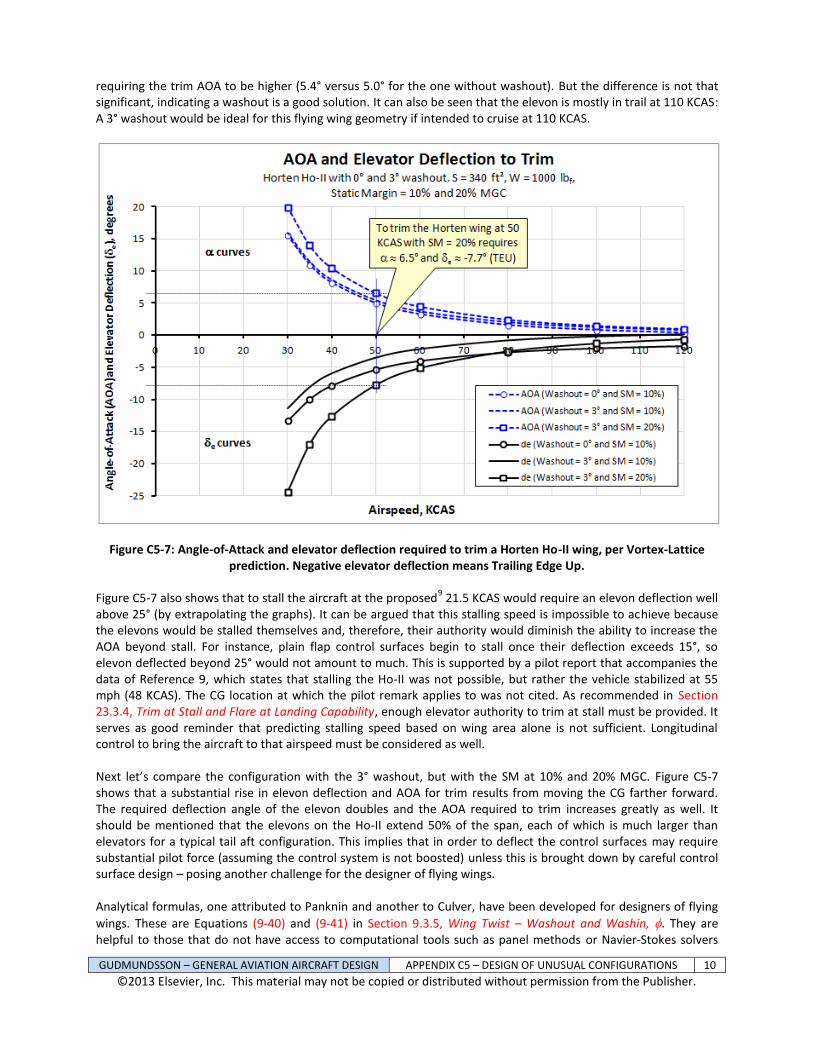
It is of interest to evaluate how the AOA and e change with airspeed. This is shown in Figure C5-7 for the Ho-II
wing with a 0° and 3° washout and an SM of 10% and 20%. The figure shows the AOA and e required to trim the vehicle as a function of airspeed. The upper half of the figure shows three curves representing the AOA and the
lower half shows three corresponding curves for the e. This begs the question: How does the washout affect the elevator deflection? Is it possible to incorporate wing washout so that neutral elevator is possible at a given design cruise condition? To investigate these questions, let’s first compare the configuration consisting of a 0° and 3° washout in Figure C5-7. The SM of both configurations is 10% MGC. The plot shows how effectively 3° of washout reduces the requirement for elevon deflection. For instance, at 50 KCAS, the configuration without washout requires about 5.4° of elevons, whereas the one with washout requires 3.4° (both TEU). At the same time, the washout makes the vehicle slightly less effective by
GUDMUNDSSON – GENERAL AVIATION AIRCRAFT DESIGN APPENDIX C5 – DESIGN OF UNUSUAL CONFIGURATIONS 10
©2013 Elsevier, Inc. This material may not be copied or distributed without permission from the Publisher.
requiring the trim AOA to be higher (5.4° versus 5.0° for the one without washout). But the difference is not that significant, indicating a washout is a good solution. It can also be seen that the elevon is mostly in trail at 110 KCAS: A 3° washout would be ideal for this flying wing geometry if intended to cruise at 110 KCAS.
Figure C5-7: Angle-of-Attack and elevator deflection required to trim a Horten Ho-II wing, per Vortex-Lattice prediction. Negative elevator deflection means Trailing Edge Up.
Figure C5-7 also shows that to stall the aircraft at the proposed9 21.5 KCAS would require an elevon deflection well
above 25° (by extrapolating the graphs). It can be argued that this stalling speed is impossible to achieve because the elevons would be stalled themselves and, therefore, their authority would diminish the ability to increase the AOA beyond stall. For instance, plain flap control surfaces begin to stall once their deflection exceeds 15°, so elevon deflected beyond 25° would not amount to much. This is supported by a pilot report that accompanies the data of Reference 9, which states that stalling the Ho-II was not possible, but rather the vehicle stabilized at 55 mph (48 KCAS). The CG location at which the pilot remark applies to was not cited. As recommended in Section 23.3.4, Trim at Stall and Flare at Landing Capability, enough elevator authority to trim at stall must be provided. It serves as good reminder that predicting stalling speed based on wing area alone is not sufficient. Longitudinal control to bring the aircraft to that airspeed must be considered as well. Next let’s compare the configuration with the 3° washout, but with the SM at 10% and 20% MGC. Figure C5-7 shows that a substantial rise in elevon deflection and AOA for trim results from moving the CG farther forward. The required deflection angle of the elevon doubles and the AOA required to trim increases greatly as well. It should be mentioned that the elevons on the Ho-II extend 50% of the span, each of which is much larger than elevators for a typical tail aft configuration. This implies that in order to deflect the control surfaces may require substantial pilot force (assuming the control system is not boosted) unless this is brought down by careful control surface design – posing another challenge for the designer of flying wings. Analytical formulas, one attributed to Panknin and another to Culver, have been developed for designers of flying
wings. These are Equations (9-40) and (9-41) in Section 9.3.5, Wing Twist – Washout and Washin, . They are helpful to those that do not have access to computational tools such as panel methods or Navier-Stokes solvers
GUDMUNDSSON – GENERAL AVIATION AIRCRAFT DESIGN APPENDIX C5 – DESIGN OF UNUSUAL CONFIGURATIONS 11
©2013 Elsevier, Inc. This material may not be copied or distributed without permission from the Publisher.
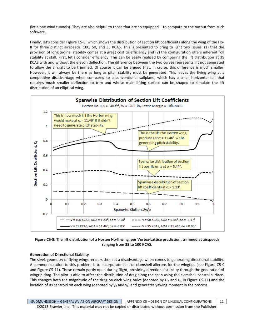
(let alone wind tunnels). They are also helpful to those that are so equipped – to compare to the output from such software. Finally, let’s consider Figure C5-8, which shows the distribution of section lift coefficients along the wing of the Ho-II for three distinct airspeeds; 100, 50, and 35 KCAS. This is presented to bring to light two issues: (1) that the provision of longitudinal stability comes at a great cost to efficiency and (2) the configuration offers inherent roll stability at stall. First, let’s consider efficiency. This can be easily realized by comparing the lift distribution at 35 KCAS with and without the elevon deflection. The difference between the two curves represents lift not generated to allow the aircraft to be trimmed. Of course it can be argued that, in cruise, this difference is much smaller. However, it will always be there as long as pitch stability must be generated. This leaves the flying wing at a competitive disadvantage when compared to a conventional sailplane, which has a small horizontal tail that requires much smaller deflection to trim and whose main lifting surface can be shaped to simulate the lift distribution of an elliptical wing.
Figure C5-8: The lift distribution of a Horten Ho-II wing, per Vortex-Lattice prediction, trimmed at airspeeds ranging from 35 to 100 KCAS.
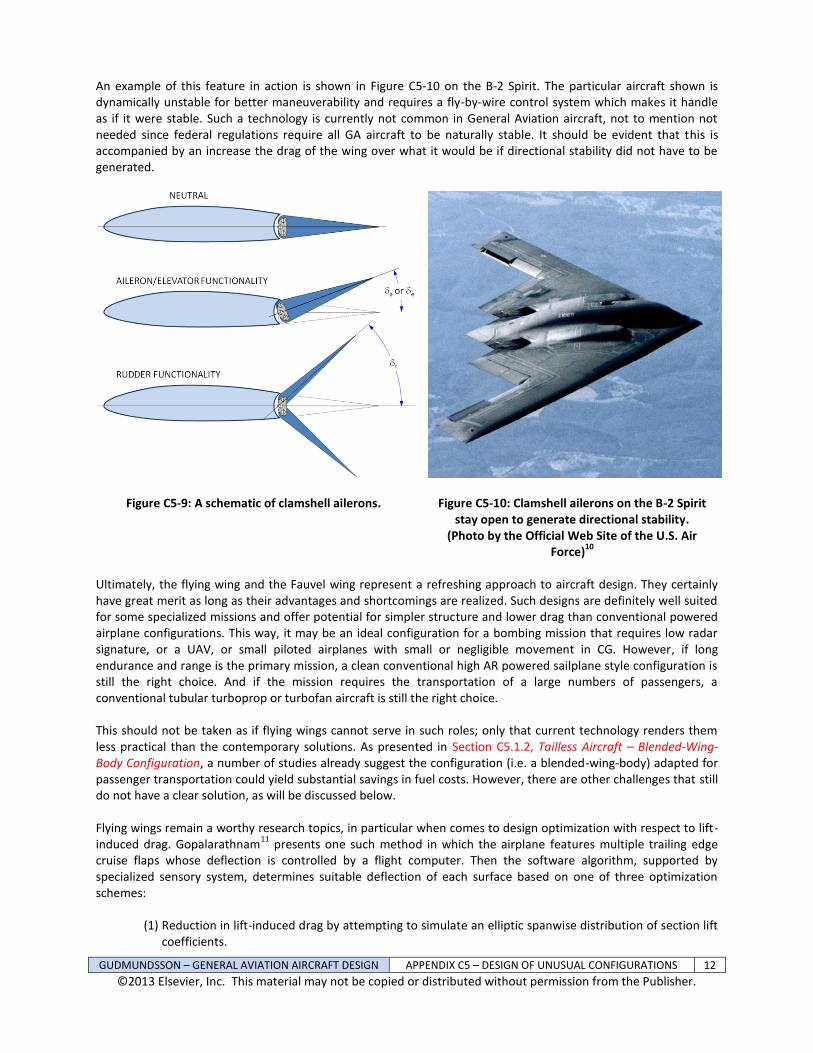
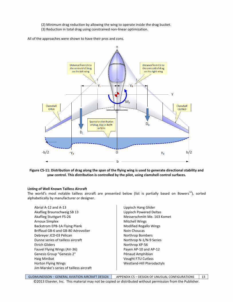
Generation of Directional Stability The sleek geometry of flying wings renders them at a disadvantage when comes to generating directional stability. A common solution to this problem is to incorporate split or clamshell ailerons for the wingtips (see Figure C5-9 and Figure C5-11). These remain partly open during flight, providing directional stability through the generation of wingtip drag. The pilot is able to affect the distribution of drag along the span using the clamshell control surface. This changes both the magnitude of the drag on each wing halve (denoted by DR and DL in Figure C5-11) and the location of its centroid on each wing (denoted by yR and yL) and generates yawing moment in the process.
GUDMUNDSSON – GENERAL AVIATION AIRCRAFT DESIGN APPENDIX C5 – DESIGN OF UNUSUAL CONFIGURATIONS 12
©2013 Elsevier, Inc. This material may not be copied or distributed without permission from the Publisher.
An example of this feature in action is shown in Figure C5-10 on the B-2 Spirit. The particular aircraft shown is dynamically unstable for better maneuverability and requires a fly-by-wire control system which makes it handle as if it were stable. Such a technology is currently not common in General Aviation aircraft, not to mention not needed since federal regulations require all GA aircraft to be naturally stable. It should be evident that this is accompanied by an increase the drag of the wing over what it would be if directional stability did not have to be generated.
Figure C5-9: A schematic of clamshell ailerons.
Figure C5-10: Clamshell ailerons on the B-2 Spirit stay open to generate directional stability.
(Photo by the Official Web Site of the U.S. Air Force)
10
Ultimately, the flying wing and the Fauvel wing represent a refreshing approach to aircraft design. They certainly have great merit as long as their advantages and shortcomings are realized. Such designs are definitely well suited for some specialized missions and offer potential for simpler structure and lower drag than conventional powered airplane configurations. This way, it may be an ideal configuration for a bombing mission that requires low radar signature, or a UAV, or small piloted airplanes with small or negligible movement in CG. However, if long endurance and range is the primary mission, a clean conventional high AR powered sailplane style configuration is still the right choice. And if the mission requires the transportation of a large numbers of passengers, a conventional tubular turboprop or turbofan aircraft is still the right choice. This should not be taken as if flying wings cannot serve in such roles; only that current technology renders them less practical than the contemporary solutions. As presented in Section C5.1.2, Tailless Aircraft – Blended-Wing-Body Configuration, a number of studies already suggest the configuration (i.e. a blended-wing-body) adapted for passenger transportation could yield substantial savings in fuel costs. However, there are other challenges that still do not have a clear solution, as will be discussed below. Flying wings remain a worthy research topics, in particular when comes to design optimization with respect to lift-induced drag. Gopalarathnam
11 presents one such method in which the airplane features multiple trailing edge
cruise flaps whose deflection is controlled by a flight computer. Then the software algorithm, supported by specialized sensory system, determines suitable deflection of each surface based on one of three optimization schemes:
(1) Reduction in lift-induced drag by attempting to simulate an elliptic spanwise distribution of section lift coefficients.
GUDMUNDSSON – GENERAL AVIATION AIRCRAFT DESIGN APPENDIX C5 – DESIGN OF UNUSUAL CONFIGURATIONS 13
©2013 Elsevier, Inc. This material may not be copied or distributed without permission from the Publisher.
(2) Minimum drag reduction by allowing the wing to operate inside the drag bucket. (3) Reduction in total drag using constrained non-linear optimization.
All of the approaches were shown to have their pros and cons.
Figure C5-11: Distribution of drag along the span of the flying wing is used to generate directional stability and yaw control. This distribution is controlled by the pilot, using clamshell control surfaces.
Listing of Well Known Tailless Aircraft The world’s most notable tailless aircraft are presented below (list is partially based on Bowers
12), sorted
alphabetically by manufacturer or designer.
Abrial A-12 and A-13 Akaflieg Braunschweig SB 13 Akaflieg Stuttgart FS-26 Arnoux Simplex Backstrom EPB-1A Flying Plank Briffaud GB-6 and GB-80 Aérovoilier Debreyer JCD-03 Pélican Dunne series of tailless aircraft Etrich Gliders Fauvel Flying Wings (AV-36) Genesis Group "Genesis 2" Haig Minibat Horton Flying Wings Jim Marske’s series of tailless aircraft
Lippisch Hang Glider Lippisch Powered Deltas Messerschmitt Me. 163 Komet Mitchell Wings Modified Rogallo Wings Noin Choucas Northrop Bombers Northrop N-1/N-9 Series Northrop XP-56 Payen AP-10 and AP-12 Pénaud Amphibian Vought F7U Cutlass Westland-Hill Pterodactyls
GUDMUNDSSON – GENERAL AVIATION AIRCRAFT DESIGN APPENDIX C5 – DESIGN OF UNUSUAL CONFIGURATIONS 14
©2013 Elsevier, Inc. This material may not be copied or distributed without permission from the Publisher.
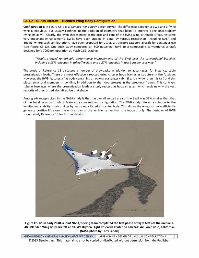
C5.1.2 Tailless Aircraft – Blended-Wing-Body Configuration
Configuration B in Figure C5-2 is a Blended-Wing-Body design (BWB). The difference between a BWB and a flying wing is nebulous, but usually confined to the addition of geometry that helps to improve directional stability (winglets as VT). Clearly, the BWB shares many of the pros and cons of the flying wing, although it features some very important enhancements. BWBs have been studied in detail by various researchers; including NASA and Boeing, where such configurations have been proposed for use as a transport category aircraft for passenger use (see Figure C5-12). One such study compared an 800 passenger BWB to a comparable conventional aircraft designed for a 7000 nm operation at Mach 0.85, stating:
“Results showed remarkable performance improvements of the BWB over the conventional baseline, including a 15% reduction in takeoff weight and a 27% reduction in fuel burn per seat mile.”
13
The study of Reference 13 discusses a number of drawbacks in addition to advantages, for instance, cabin pressurization loads. These are most effectively reacted using circular hoop frames as structure in the fuselage. However, the BWB features a flat body containing an oblong passenger cabin (i.e. it is wider than it is tall) and this places structural members in bending, in addition to the hoop stresses in the structural frames. This contrasts tubular fuselages where the pressurization loads are only reacted as hoop stresses, which explains why the vast majority of pressurized aircraft utilize that shape. Among advantages cited in the NASA study is that the overall wetted area of the BWB was 33% smaller than that of the baseline aircraft, which featured a conventional configuration. The BWB study offered a solution to the longitudinal stability shortcomings by featuring a flexed aft center body. This allows the wings to more efficiently generate positive lift along the entire span of the vehicle, rather than the inboard only. The designer of BWB should study Reference 13 for further details.
Figure C5-12: In early 2010, a joint NASA/Boeing team completed the first phase of flight tests of the unique X-48B Blended Wing Body aircraft at NASA's Dryden Flight Research Center on Edwards Air Force Base, California.
(NASA photo by Tony Landis)
GUDMUNDSSON – GENERAL AVIATION AIRCRAFT DESIGN APPENDIX C5 – DESIGN OF UNUSUAL CONFIGURATIONS 15
©2013 Elsevier, Inc. This material may not be copied or distributed without permission from the Publisher.
In order to justify the BWB, the importance of airframe weight due to a stress rise in the fuselage frames must be demoted in favor of the improvements in fuel efficiency that results from its external shape. Another drawback, shared by some flying wing configurations, is that it becomes unstable at high AOA (e.g. during T-O rotation or flare), due to reasons already explained. Variability in passenger loading can lead to a large shift in CG, which the configuration is ill-equipped to handle naturally. For this reason, such airplanes should be controlled using a Stability Augmentation System (SAS) or a fly-by-wire technology. The geometry’s cranked planform shape and protruding forward section, which distorts the pressure field such that non-linearity in the longitudinal pitching moment is introduced, also contributes to the instability at higher AOAs. Among other disadvantages that apply directly to the BWB is that high lift devices, such as trailing edge flaps cannot be utilized due to the inability to trim at the higher pitching moments. This makes the aircraft unable to develop a high CLmax, and the CLmax developed requires a high deck angle and higher T-O and landing airspeeds. Assuming a large passenger transport aircraft, the comparatively short moment arms require multiple and large control surfaces. A BWB controlled by a fly-by-wire system would call for these control surfaces to be capable of rapid deflection. The power required for this actuation may pose a significant challenge with the current technology. Airplane growth can no longer be accomplished by adding plugs to the fuselage, but would be accomplished by widening the aircraft. This could inflict further limitations on the number of airport the vehicle could be operated from. Ride quality of the passengers sitting farthest from the CG is a common concern, but has been shown to be comparable to conventional aircraft – quite possibly better in the BWB (Reference 13).
C5.1.3 Tailless Aircraft – Fauvel Wings and Flying Planks
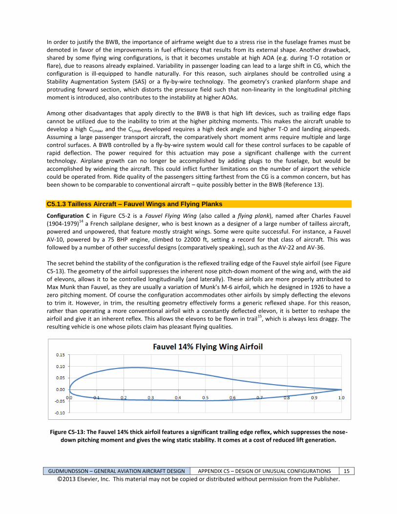
Configuration C in Figure C5-2 is a Fauvel Flying Wing (also called a flying plank), named after Charles Fauvel (1904-1979)
14 a French sailplane designer, who is best known as a designer of a large number of tailless aircraft,
powered and unpowered, that feature mostly straight wings. Some were quite successful. For instance, a Fauvel AV-10, powered by a 75 BHP engine, climbed to 22000 ft, setting a record for that class of aircraft. This was followed by a number of other successful designs (comparatively speaking), such as the AV-22 and AV-36. The secret behind the stability of the configuration is the reflexed trailing edge of the Fauvel style airfoil (see Figure C5-13). The geometry of the airfoil suppresses the inherent nose pitch-down moment of the wing and, with the aid of elevons, allows it to be controlled longitudinally (and laterally). These airfoils are more properly attributed to Max Munk than Fauvel, as they are usually a variation of Munk’s M-6 airfoil, which he designed in 1926 to have a zero pitching moment. Of course the configuration accommodates other airfoils by simply deflecting the elevons to trim it. However, in trim, the resulting geometry effectively forms a generic reflexed shape. For this reason, rather than operating a more conventional airfoil with a constantly deflected elevon, it is better to reshape the airfoil and give it an inherent reflex. This allows the elevons to be flown in trail
15, which is always less draggy. The
resulting vehicle is one whose pilots claim has pleasant flying qualities.
Figure C5-13: The Fauvel 14% thick airfoil features a significant trailing edge reflex, which suppresses the nose-down pitching moment and gives the wing static stability. It comes at a cost of reduced lift generation.
GUDMUNDSSON – GENERAL AVIATION AIRCRAFT DESIGN APPENDIX C5 – DESIGN OF UNUSUAL CONFIGURATIONS 16
©2013 Elsevier, Inc. This material may not be copied or distributed without permission from the Publisher.
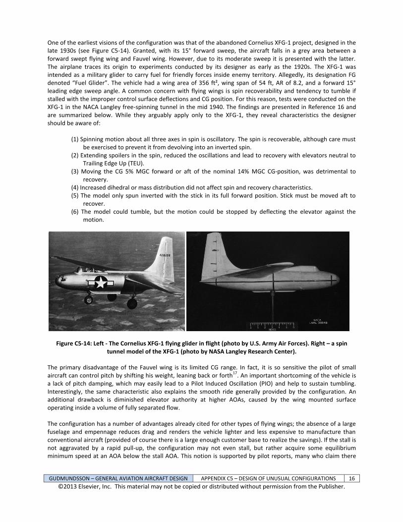
One of the earliest visions of the configuration was that of the abandoned Cornelius XFG-1 project, designed in the late 1930s (see Figure C5-14). Granted, with its 15° forward sweep, the aircraft falls in a grey area between a forward swept flying wing and Fauvel wing. However, due to its moderate sweep it is presented with the latter. The airplane traces its origin to experiments conducted by its designer as early as the 1920s. The XFG-1 was intended as a military glider to carry fuel for friendly forces inside enemy territory. Allegedly, its designation FG denoted “Fuel Glider”. The vehicle had a wing area of 356 ft², wing span of 54 ft, AR of 8.2, and a forward 15° leading edge sweep angle. A common concern with flying wings is spin recoverability and tendency to tumble if stalled with the improper control surface deflections and CG position. For this reason, tests were conducted on the XFG-1 in the NACA Langley free-spinning tunnel in the mid 1940. The findings are presented in Reference 16 and are summarized below. While they arguably apply only to the XFG-1, they reveal characteristics the designer should be aware of:
(1) Spinning motion about all three axes in spin is oscillatory. The spin is recoverable, although care must be exercised to prevent it from devolving into an inverted spin.
(2) Extending spoilers in the spin, reduced the oscillations and lead to recovery with elevators neutral to Trailing Edge Up (TEU).
(3) Moving the CG 5% MGC forward or aft of the nominal 14% MGC CG-position, was detrimental to recovery.
(4) Increased dihedral or mass distribution did not affect spin and recovery characteristics. (5) The model only spun inverted with the stick in its full forward position. Stick must be moved aft to
recover. (6) The model could tumble, but the motion could be stopped by deflecting the elevator against the
motion.
Figure C5-14: Left - The Cornelius XFG-1 flying glider in flight (photo by U.S. Army Air Forces). Right – a spin tunnel model of the XFG-1 (photo by NASA Langley Research Center).
The primary disadvantage of the Fauvel wing is its limited CG range. In fact, it is so sensitive the pilot of small aircraft can control pitch by shifting his weight, leaning back or forth
17. An important shortcoming of the vehicle is
a lack of pitch damping, which may easily lead to a Pilot Induced Oscillation (PIO) and help to sustain tumbling. Interestingly, the same characteristic also explains the smooth ride generally provided by the configuration. An additional drawback is diminished elevator authority at higher AOAs, caused by the wing mounted surface operating inside a volume of fully separated flow. The configuration has a number of advantages already cited for other types of flying wings; the absence of a large fuselage and empennage reduces drag and renders the vehicle lighter and less expensive to manufacture than conventional aircraft (provided of course there is a large enough customer base to realize the savings). If the stall is not aggravated by a rapid pull-up, the configuration may not even stall, but rather acquire some equilibrium minimum speed at an AOA below the stall AOA. This notion is supported by pilot reports, many who claim there
GUDMUNDSSON – GENERAL AVIATION AIRCRAFT DESIGN APPENDIX C5 – DESIGN OF UNUSUAL CONFIGURATIONS 17
©2013 Elsevier, Inc. This material may not be copied or distributed without permission from the Publisher.
are no surprising “stall-breaks.” This characteristic can almost certainly be attributed to diminished elevator authority due to flow separation. The configuration offers good gust penetration characteristics, attributed to the low moment of inertia about its pitch axis and low pitch damping. As the vehicle penetrates a vertical up- or downdraft, its static stability rapidly aligns it with the change in AOA. For instance, an updraft will momentarily increase the AOA experienced by the craft. The effect of the updraft is not “felt” instantaneously, but gradually (a fact accounted for in standard gust load analysis using the concept of gust alleviation). While the time it takes the updraft to reach its maximum value is short indeed, the aircraft’s minute moment of inertia allows it to quickly seek the originally trimmed-to AOA. For an updraft this will be manifested as a nose-down pitching moment and nose-up pitching moment for a downdraft. The fact that the occupant sits very close to the CG and, thus, will simply not detect gust acceleration due to the angular motion of the aircraft should not be overlooked either. All in all, the configuration is touted as one that offers a great compromise between safety, cost, performance, and simplicity
18.
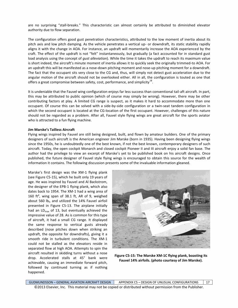
It is undeniable that the Fauvel wing configuration enjoys far less success than conventional tail-aft aircraft. In part, this may be attributed to public opinion (which of course may simply be wrong). However, there may be other contributing factors at play. A limited CG range is suspect, as it makes it hard to accommodate more than one occupant. Of course this can be solved with a side-by-side configuration or a twin-seat tandem configuration in which the second occupant is located at the CG-location of the first occupant. However, challenges of this nature should not be regarded as a problem. After all, Fauvel style flying wings are great aircraft for the sports aviator who is attracted to a fun flying machine. Jim Marske’s Tailless Aircraft Flying wings inspired by Fauvel are still being designed, built, and flown by amateur builders. One of the primary designers of such aircraft is the American engineer Jim Marske (born in 1935). Having been designing flying wings since the 1950s, he is undoubtedly one of the best known, if not the best known, contemporary designers of such aircraft. Today, the open cockpit Monarch and closed cockpit Pioneer II and III aircraft enjoy a solid fan base. The author had the privilege to view an excerpt of Marske’s yet to be published book on his aircraft designs. Once published, the future designer of Fauvel style flying wings is encouraged to obtain this source for the wealth of information it contains. The following discussion presents some of the invaluable information gleaned. Marske’s first design was the XM-1 flying plank (see Figure C5-15), which he built only 19 years of age. He was inspired by Fauvel and Al Backstrom, the designer of the EPB-1 flying plank, which also dates back to 1954. The XM-1 had a wing area of 160 ft², wing span of 38.1 ft, AR of 9, weighed about 560 lbf, and utilized the 14% Fauvel airfoil presented in Figure C5-13. The airplane initially had an LDmax of 13, but eventually achieved the impressive value of 28. As is common for this type of aircraft, it had a small CG range. It displayed the same response to vertical gusts already described (nose pitches down when striking an updraft, the opposite for downdrafts), giving it a smooth ride in turbulent conditions. The XM-1 could not be stalled as the elevators reside in separated flow at high AOA. Attempts to spin the aircraft resulted in skidding turns without a nose drop. Accelerated stalls at 45° bank were achievable, causing an immediate forward pitch, followed by continued turning as if nothing happened.
Figure C5-15: The Marske XM-1C flying plank, boasting its Fauvel 14% airfoils. (photo courtesy of Jim Marske).
GUDMUNDSSON – GENERAL AVIATION AIRCRAFT DESIGN APPENDIX C5 – DESIGN OF UNUSUAL CONFIGURATIONS 18
©2013 Elsevier, Inc. This material may not be copied or distributed without permission from the Publisher.
Marske’s next design was the Pioneer I, which later became the Pioneer II, III, and V. The Pioneer I dates back to the late 1960s. It utilized the NACA 23112 airfoil, which as can be seen in Section 8.2.3, NACA 5-Digit Airfoils, is the reflexed version of the well known NACA 23012 airfoil. With a gross weight around 700 lbf, its wing area was 190 ft², wing span was 40 ft, and AR was 8.4. Flight tests were carried out on a lakebed in the Mojave desert in March 1968. The pitch control of the Pioneer I was reported as very docile, with a noticeable lack of inertia in pitch. It was claimed that rapid pitch changes could be made without tendency to overshoot the new attitude. Rather than using conventional ailerons, roll control was provided using devices referred to as roll-spoilers. As is so common among flying wings, the Pioneer I would not stall, most likely due to a lack of elevator authority at high AOA. Rather, a low frequency buffet would be experienced. It was possible to stall the airplane with more aggressive pull-up, although this resulted in a high pitch attitude followed by a gentle break and subsequent recovery with little loss of altitude. Accelerated stalls were docile as well, with a bank angle being maintained. The airplane could not be held in a stalled condition and, it was claimed, would not enter spin. With respect to handling, the aircraft was found to be statically stable about all three axes. Like the XM-1, it suffered from a limited CG range. Its phugoid was convergent with period of 17 seconds and was only noticed if the control stick was free to move. It was spirally divergent, with time to double the initial displacement exceeding one minute, allowing plenty of time for a pilot response. The divergent spiral mode required the roll-spoiler to be constantly deployed and supported by rudder deflection. This, inevitably, increased the drag of the vehicle. The Dutch roll mode was convergent. Roll spoilers produced coordinated turns below 52 KCAS, but above, progressively worse skidding turns were experienced. High speed turns were made using the rudder, allowing the dihedral effect develop the roll. The low pitch damping and moment of inertia about the pitch axis enabled the aircraft to quickly react to vertical gusts, providing a kind of automatic gust alleviation. Experiments on models of the flying wing indicated that unrecoverable tumbling would only occur if the CG was located aft of the 35% MGC. With CG at the 30% MGC it would tumble once or twice before recovering. The aft CG limit of the aircraft was 25% MGC. Tumbling can be initiated by placing the sailplane into a vertical climb, where it is held until it stalls completely and begins a tail-slide. This will cause it to whip over on its back and begin to rotate the nose upwards. The Pioneer I became the Pioneer IA through modifications. Among those was an increase in span from 40 to 46 ft. The aerodynamic properties of the rudder were improved. Surprisingly, the IA was 30 lbf lighter than Pioneer I. The first flight of the modified aircraft took place in August 1968. It was found that the roll-spoilers were ineffective. The remedy was to cut special ports into the spoiler tray to modify the flow field when deployed. The change improved the roll rate at 50 knots from 10°/sec to 18°/sec, which was considered adequate albeit slower than desirable. The Pioneer IA handled well in crosswinds. It had split flaps (called drag flaps) hinged at the mid-chord point on the lower surface of the wing. At low speeds, there was a negligible trim change, but at airspeed over 70 KCAS the control stick would buffet due to flow separation behind the flap that would carry through the elevator control system. Overall the flaps were considered ineffective and increased floating tendency in ground effect. It was observed that the airplane had a minimum airspeed 28 KCAS, so determined as it could not be stalled. Its airspeed of minimum sink rate was 46 KCAS. The best glide speed was 50 KCAS with an LDmax of 34. It was frequently flown at airspeed as high as 160 KCAS and even flown above 31000 ft in a mountain wave. The Pioneer IA was redesigned to allow it to be produced as a kitplane. The model was called the Pioneer II. Further development yielded the Pioneer II-D, a version with a modified wing and vertical tail (see Figure C5-16). In 2004, the Pioneer III was introduced, with the latest revision being the Pioneer V.
GUDMUNDSSON – GENERAL AVIATION AIRCRAFT DESIGN APPENDIX C5 – DESIGN OF UNUSUAL CONFIGURATIONS 19
©2013 Elsevier, Inc. This material may not be copied or distributed without permission from the Publisher.
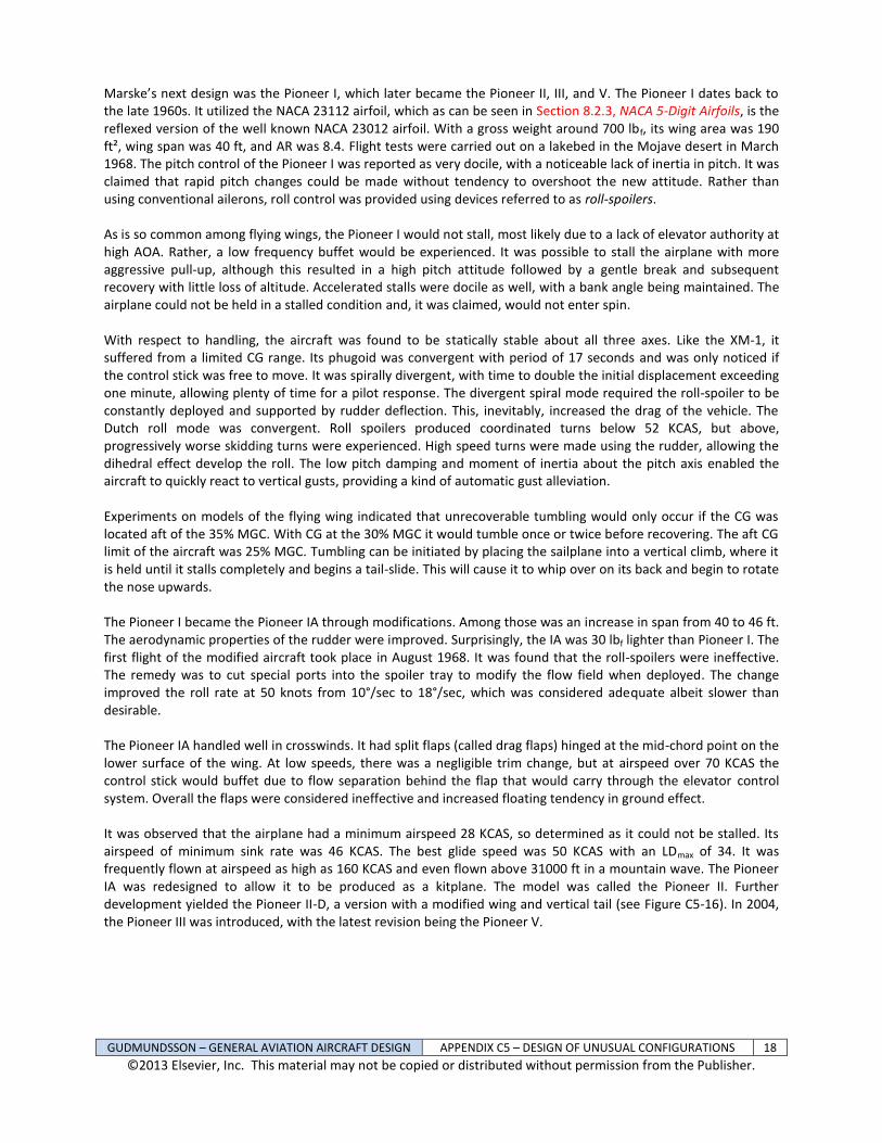
Figure C5-16: A Marske Pioneer II-D, single seat flying wing in flight (photo courtesy of Jim Marske).
C5.1.4 Asymmetric Aircraft
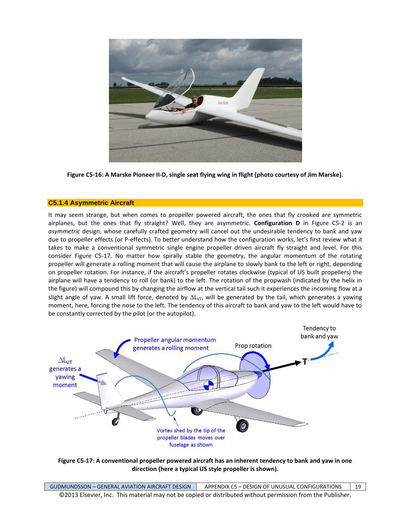
It may seem strange, but when comes to propeller powered aircraft, the ones that fly crooked are symmetric airplanes, but the ones that fly straight? Well, they are asymmetric. Configuration D in Figure C5-2 is an asymmetric design, whose carefully crafted geometry will cancel out the undesirable tendency to bank and yaw due to propeller effects (or P-effects). To better understand how the configuration works, let’s first review what it takes to make a conventional symmetric single engine propeller driven aircraft fly straight and level. For this consider Figure C5-17. No matter how spirally stable the geometry, the angular momentum of the rotating propeller will generate a rolling moment that will cause the airplane to slowly bank to the left or right, depending on propeller rotation. For instance, if the aircraft’s propeller rotates clockwise (typical of US built propellers) the airplane will have a tendency to roll (or bank) to the left. The rotation of the propwash (indicated by the helix in the figure) will compound this by changing the airflow at the vertical tail such it experiences the incoming flow at a
slight angle of yaw. A small lift force, denoted by LVT, will be generated by the tail, which generates a yawing moment, here, forcing the nose to the left. The tendency of this aircraft to bank and yaw to the left would have to be constantly corrected by the pilot (or the autopilot).
Figure C5-17: A conventional propeller powered aircraft has an inherent tendency to bank and yaw in one direction (here a typical US style propeller is shown).
GUDMUNDSSON – GENERAL AVIATION AIRCRAFT DESIGN APPENDIX C5 – DESIGN OF UNUSUAL CONFIGURATIONS 20
©2013 Elsevier, Inc. This material may not be copied or distributed without permission from the Publisher.
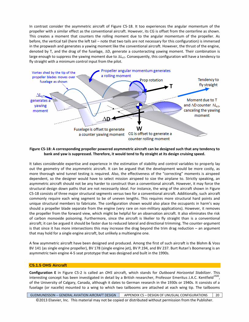
In contrast consider the asymmetric aircraft of Figure C5-18. It too experiences the angular momentum of the propeller with a similar effect as the conventional aircraft. However, its CG is offset from the centerline as shown. This creates a moment that counters the rolling moment due to the angular momentum of the propeller. As before, the vertical tail (here the left tail – note that two tails are not necessary for this configuration) is immersed in the propwash and generates a yawing moment like the conventional aircraft. However, the thrust of the engine,
denoted by T, and the drag of the fuselage, D, generate a counteracting yawing moment. Their combination is
large enough to suppress the yawing moment due to LVT. Consequently, this configuration will have a tendency to fly straight with a minimum control input from the pilot.
Figure C5-18: A corresponding propeller powered asymmetric aircraft can be designed such that any tendency to bank and yaw is suppressed. Therefore, it would tend to fly straight at its design cruising speed.
It takes considerable expertise and experience in the estimation of stability and control variables to properly lay out the geometry of the asymmetric aircraft. It can be argued that the development would be more costly, as more thorough wind tunnel testing is required. Also, the effectiveness of the “correcting” moments is airspeed dependent, so the designer would have to select mission airspeed to size the airplane to. Strictly speaking, an asymmetric aircraft should not be any harder to construct than a conventional aircraft. However, it may force the structural design down paths that are not necessarily ideal. For instance, the wing of the aircraft shown in Figure C5-18 consists of three major structural segments versus two for a conventional aircraft. Additionally, such aircraft commonly require each wing segment to be of uneven lengths. This requires more structural hard points and unique structural members to fabricate. The configuration shown would also place the occupants in harm’s way should a propeller blade separate from the engine (very rare on non-military applications). However, it removes the propeller from the forward view, which might be helpful for an observation aircraft. It also eliminates the risk of carbon monoxide poisoning. Furthermore, since the aircraft is likelier to fly straight than is a conventional aircraft; it can be argued it should be faster due to reduced lateral and directional trimming. The counter-argument is that since it has more intersections this may increase the drag beyond the trim drag reduction – an argument that may hold for a single engine aircraft, but unlikely a multiengine one. A few asymmetric aircraft have been designed and produced. Among the first of such aircraft is the Blohm & Voss BV 141 (as single engine propeller), BV 178 (single engine jet), BV P.194, and BV 237. Burt Rutan’s Boomerang is an asymmetric twin engine 4-5 seat prototype that was designed and built in the 1990s.
C5.1.5 OHS Aircraft
Configuration E in Figure C5-2 is called an OHS aircraft, which stands for Outboard Horizontal Stabilizer. This interesting concept has been investigated in detail by a British researcher, Professor Emeritus J.A.C. Kentfield
1920,
of the University of Calgary, Canada, although it dates to German research in the 1930s or 1940s. It consists of a fuselage (or nacelle) mounted to a wing to which two tailbooms are attached at each wing tip. The tailbooms
GUDMUNDSSON – GENERAL AVIATION AIRCRAFT DESIGN APPENDIX C5 – DESIGN OF UNUSUAL CONFIGURATIONS 21
©2013 Elsevier, Inc. This material may not be copied or distributed without permission from the Publisher.
feature horizontal and vertical stabilizers mounted downwind as shown in Figure C5-2. The primary idea is to place the horizontal stabilizer in the upwash generated by the wingtip vortices. This places the surface at a positive AOA and the resulting lift will point in the same direction as the wing lift and contrasts a conventional configuration, which produces lift that points downward. This way, the stabilizer of the OHS generates a stabilizing nose pitch-down moment while simultaneously augmenting the lift, not unlike a canard configuration (of course the canard generates a destabilizing nose pitch-up moment, while augmenting the wing lift). As stated above, the OHS concept is not new, as it was developed by German scientists in the Second World War. Several similar configurations were designed by Blohm und Voss, who arguably were the most original and creative aircraft design agency in the History of Aviation. Blohm und Voss designed the BV P.208.03, BV P.209.01, BV P.210, BV P.212, and BV P.215.02 series of fighter aircraft. The Skoda-Kauba SL-6 was a small aircraft built to test the control system of the BV P.208.03. Additionally, Scaled Composites’ SpaceShipOne features this configuration as well. Reference 19 states that for a comparable Aspect Ratio and other operational parameters the OHS offers approximately 20% less drag and 15% smaller planform area over a conventional design. If true, this would translate into less wetted area and, thus, less drag and improved performance. It can be argued that the tailboom configuration is less susceptible to flutter, as an upward deflection of the tailboom inherently reduces the AOA of the wing with deflection, not unlike a swept back wing. Additionally, it can be argued that the twin tailbooms of the OHS provides bending moment relief as the weight of the booms and the stabilizing surfaces will be reacted by the wingtip – providing maximum bending relief possible. This is clearly advantageous and should lighten the wing structure. However, it is a drawback that the moment generated by the horizontal tail loads, and is reacted at the wing tip, can induce substantial washin or washout (depending on elevator deflection) in the main wing as it acts over the half span of the wing. Also, the control system will be more complicated as a set of cable-pulleys or pushrods must be directed outboard, through each wing half, toward each tailboom to allow the elevator and rudder to be controlled. Such complication would exceed even that of a conventional twin tailboom configuration. Therefore, from the standpoint of flutter, the deflection of both the left and right elevator and rudder is in fact independent of each other. It is analogous to the of the Handley Page 0/400 bomber of World War I. It suffered from a 4 Hz tail wobble due to the elevator surfaces on either side of the plane of symmetry, were independent
21.
At first glance, one might argue that this is not the case, because such a control system would feature connectivity and, therefore, deflecting one elevator or rudder will deflect the opposite one too. However, when comes to flutter, this is insufficient because the control system is inherently flexible, in particular if it is manually operated. For instance, even if the left rudder were to be held firmly, the right one could still be deflected due to the flexibility of the control system. And even though the deflection would be constrained and small, perhaps 2-3°, this would suffice to make the vehicle more flutter prone. Consequently, if intended for a small aircraft, the control system would have to be very stiff and this would make it more expensive to manufacture. Of course, properly mass balancing the control surfaces would help some, but ultimately such an airplane would more likely than not require stricter adherence to tolerance limits than a conventional aircraft.
GUDMUNDSSON – GENERAL AVIATION AIRCRAFT DESIGN APPENDIX C5 – DESIGN OF UNUSUAL CONFIGURATIONS 22
©2013 Elsevier, Inc. This material may not be copied or distributed without permission from the Publisher.
REFERENCES 1 Pape, Garry R., Northrop Flying Wings – A History of Jack Northrop’s Visionary Aircraft, Schiffer Military History
Publishing, 1995. 2 Myhra, David, The Horten Brothers and Their All-Wing Aircraft, Schiffer Military History Publishing, 1998.
3 NACA WR-L5G23, Effect of Wing Modifications on the Longitudinal Stability of a Tailless All-Wing Airplane Model,
Seacord, Jr., Charles L. and Herman O. Ankenbruck, 1945. 4 Horten, Dr. Reimar, Veleritos 'Sin Cola', Revista Nacional de Aeronautica, No. 10, pg. 17-18; Buenos Aires,
Argentina, October 1949. 5 Horten, Dr. Reimar, Planeadores 'Alas Volantes', Revista Nacional de Aeronautica, No. 139, pg. 46-47; Buenos
Aires, Argentina, October 1953. 6 Nickel, Karl and Michael Wohlfahrt, Tailless Aircraft in Theory and Practice, AIAA Education Series, 1994, pg. 26-
28. 7 Stinton, Darrol, The Design of the Aeroplane, Collins Professional and Technical Books, 1983.
8 Source: http://www.marskeaircraft.com/aboutus.html
9 Source: http://www.nurflugel.com/Nurflugel/Horten_Nurflugels/horten_nurflugels.html
10 Source: http://www.af.mil/photos.
11 Gopalarathnam, Ashok and Aaron A. Cusher, Drag Reduction Methodology for Adaptive Tailless Aircraft, Journal
of Aircraft, Vol. 49, No. 1, January–February 2012. 12
Bowers, Peter M., Unconventional Aircraft, 2nd Ed., TAB Books 1990. 13
Source: Liebeck, R. H., Design of the Blended Wing Body Subsonic Transport, JOURNAL OF AIRCRAFT, Vol. 41, No. 1, January–February 2004. 14
Source: http://www.nurflugel.com/Nurflugel/Fauvel/e_biograph.htm states 1904 as Charles’ birthyear, while the year 1905 is stated in an article by Georges Jacquemin, which appeared in Sport Aviation, April 1962. 15
In trail means the control surface is neutrally deflected. 16
NACA WR-L-738, Free-Spinning, Longitudinal-Trim, and Tumbling Tests of the 1/17.8 Scale Models of the Cornelius XFG-1 Glider, Stone, Jr., Ralph W. and Lee T. Daughtridge, Jr., 1946. 17
Lambie, Jack, Flying the Fauvel AV-36 Flying Wing, http://www.nurflugel.com/Nurflugel/Fauvel/e_vol.htm. 18
Source: Why a Flying Wing, http://www.nurflugel.com/Nurflugel/Fauvel/e_pourquoi.htm. 19
Kentfield, J. A. C., The Aspect-Ratio Equivalence of Conventional Aircraft with Configurations Featuring Outboard Horizontal Stabilizers, AIAA-1997-5591, 1997 20
Kentfield, J. A. C., Upwash Flowfields at the Tails of Aircraft with Outboard Horizontal Stabilizers, AIAA-1998-0757, 1998. 21
Barnes, Charles Henry, Handley Page Aircraft Since 1907, Putnam & Company, 1987