Embed Size (px)
Citation preview
Detectors for Fourier Transform SpectroscopyApplicationNote: 50808
Key Words
• Detector
• FT-IR
• Responsivity
• Sampling BeamGeometry
• SpecificDetectivity
Thermo Scientific FT-IR spectrometers can be configuredto meet your need to produce the highest performancespectral data for a wide variety of applications. Optimizationfor each application requires the selection of specific systemcomponents – source, optics, electronics, interferometer,beamsplitter, and detector – to produce the best qualityspectrum. Of these components, the detector is key, as itcan be matched uniquely to specific applications. Thechoice of the ideal detector for spectral measurement isdependent upon many factors, including:
• Sensitivity
• Spectral range of the measurement
• Sampling beam geometry
• Temporal resolution of the data collection
• Spectral resolution
• Response time
This note will describe the unique features of detectorsfor vibrational spectroscopy, focusing primarily on Fouriertransform infrared (FT-IR). It will help guide the choicefor the ideal detector for specific applications.
High throughput (greater than 20% of IR beam reachingthe IR detector) and static experiments are generally runutilizing a thermal detector, such as deuterated, L-alaninedoped triglycine sulfate (DLaTGS), because it gives full,specific detectivity (D*) in high-flux environments. Froman applications perspective, the DLaTGS detector provides linear response over a wide range of FT-IR throughput,which is beneficial in qualitative and quantitative FT-IRsampling. Thermal detectors are generally less effective for kinetic measurements because their signal is inverselyproportional to data collection speed. Low-throughputexperiments (less than 20% of IR beam reaching thedetector) benefit from the use of a quantum detector, suchas the mercuric cadmium telluride (MCT) detector. High MCT sensitivity yields good IR signal in a low-fluxmeasurement. Furthermore, the MCT detector exhibits arelatively constant signal versus data-collection speed andis, therefore, ideal for kinetic measurements. A limitationof MCT detectors is that they lose responsivity and D*athigh throughput. From the applications perspective, thismeans that in high-throughput applications, we must limit
the beam energy reaching the MCT detector to preventsaturation, where the detector responds with a non-linearsignal. Limiting the beam energy can be done by usingneutral density filters, or optical screens.
Vibrational spectroscopy detector specifications are listedin Table 1. DLaTGS is a high-performance element whichprovides higher sensitivity than older technology based ondeuterated triglycine sulfate (DTGS) detector elements.
Element size is reported in terms of diameter (mm) for circular detector elements, or area (mm2), with x, ydimensions for quadrangular shaped elements. Ideally, systems are designed to match the beam diameter anddetector element size – not over-filling or under-filling thedetector element. A significantly over-filled detector elementwill not measure the full system flux and, consequentially,the signal-to-noise ratio will be diminished. This must bebalanced with the fact that detector noise increases withincreased detector area. To prevent saturation in high-D*detectors, reducing the beam intensity by reducing thebeam diameter is not effective. Any area of the detectorthat is saturated will demonstrate saturation in the resulting spectrum. Figure 1 shows examples of an MCT-A, DLaTGS (with Validation Wheel option) andInGaAs detectors.
Figure 1: Vibrational spectroscopy detectors use a pre-aligned, pinned-in-place design and may be repositioned to other system locations with automatic recognition
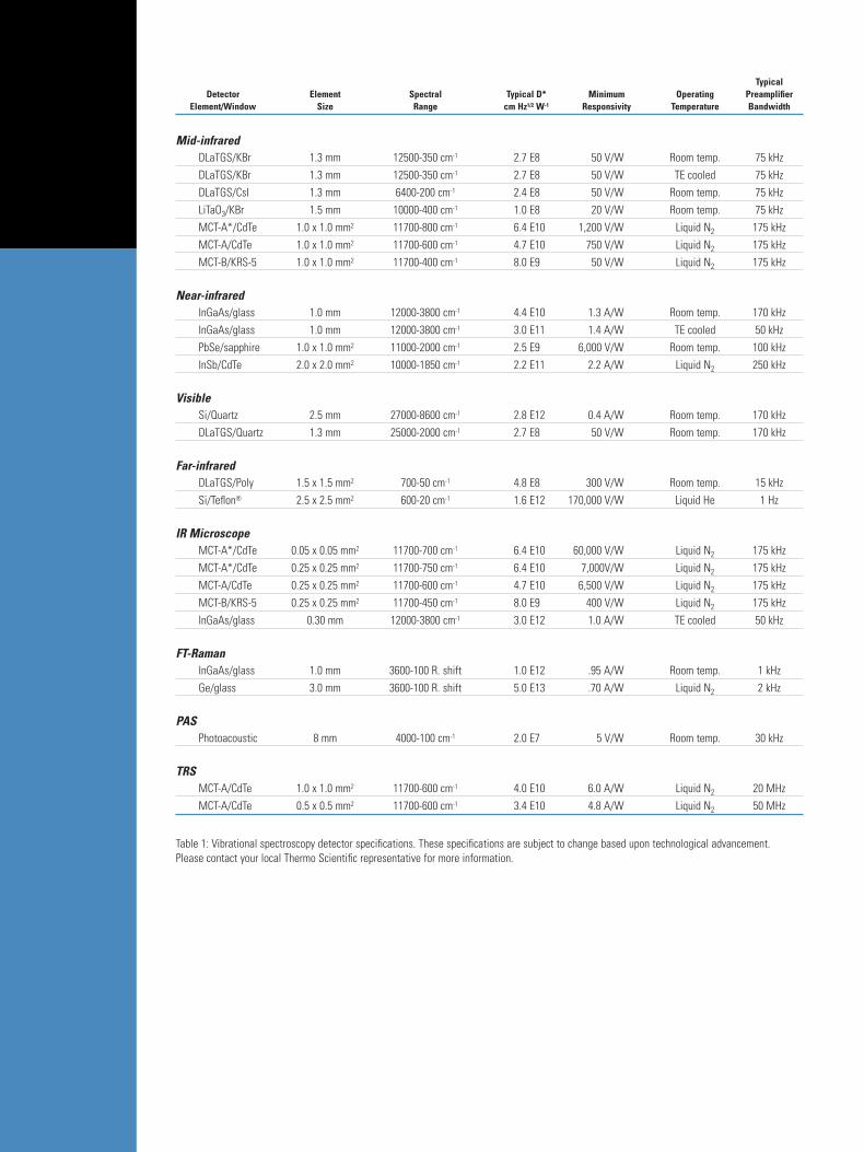
TypicalDetector Element Spectral Typical D* Minimum Operating Preamplifier
Element/Window Size Range cm Hz1/2 W-1 Responsivity Temperature Bandwidth
Mid-infraredDLaTGS/KBr 1.3 mm 12500-350 cm-1 2.7 E8 50 V/W Room temp. 75 kHzDLaTGS/KBr 1.3 mm 12500-350 cm-1 2.7 E8 50 V/W TE cooled 75 kHzDLaTGS/CsI 1.3 mm 6400-200 cm-1 2.4 E8 50 V/W Room temp. 75 kHzLiTaO3/KBr 1.5 mm 10000-400 cm-1 1.0 E8 20 V/W Room temp. 75 kHzMCT-A*/CdTe 1.0 x 1.0 mm2 11700-800 cm-1 6.4 E10 1,200 V/W Liquid N2 175 kHzMCT-A/CdTe 1.0 x 1.0 mm2 11700-600 cm-1 4.7 E10 750 V/W Liquid N2 175 kHzMCT-B/KRS-5 1.0 x 1.0 mm2 11700-400 cm-1 8.0 E9 50 V/W Liquid N2 175 kHz
Near-infraredInGaAs/glass 1.0 mm 12000-3800 cm-1 4.4 E10 1.3 A/W Room temp. 170 kHzInGaAs/glass 1.0 mm 12000-3800 cm-1 3.0 E11 1.4 A/W TE cooled 50 kHzPbSe/sapphire 1.0 x 1.0 mm2 11000-2000 cm-1 2.5 E9 6,000 V/W Room temp. 100 kHzInSb/CdTe 2.0 x 2.0 mm2 10000-1850 cm-1 2.2 E11 2.2 A/W Liquid N2 250 kHz
VisibleSi/Quartz 2.5 mm 27000-8600 cm-1 2.8 E12 0.4 A/W Room temp. 170 kHzDLaTGS/Quartz 1.3 mm 25000-2000 cm-1 2.7 E8 50 V/W Room temp. 170 kHz
Far-infraredDLaTGS/Poly 1.5 x 1.5 mm2 700-50 cm-1 4.8 E8 300 V/W Room temp. 15 kHzSi/Teflon® 2.5 x 2.5 mm2 600-20 cm-1 1.6 E12 170,000 V/W Liquid He 1 Hz
IR MicroscopeMCT-A*/CdTe 0.05 x 0.05 mm2 11700-700 cm-1 6.4 E10 60,000 V/W Liquid N2 175 kHz MCT-A*/CdTe 0.25 x 0.25 mm2 11700-750 cm-1 6.4 E10 7,000V/W Liquid N2 175 kHzMCT-A/CdTe 0.25 x 0.25 mm2 11700-600 cm-1 4.7 E10 6,500 V/W Liquid N2 175 kHzMCT-B/KRS-5 0.25 x 0.25 mm2 11700-450 cm-1 8.0 E9 400 V/W Liquid N2 175 kHzInGaAs/glass 0.30 mm 12000-3800 cm-1 3.0 E12 1.0 A/W TE cooled 50 kHz
FT-RamanInGaAs/glass 1.0 mm 3600-100 R. shift 1.0 E12 .95 A/W Room temp. 1 kHzGe/glass 3.0 mm 3600-100 R. shift 5.0 E13 .70 A/W Liquid N2 2 kHz
PASPhotoacoustic 8 mm 4000-100 cm-1 2.0 E7 5 V/W Room temp. 30 kHz
TRSMCT-A/CdTe 1.0 x 1.0 mm2 11700-600 cm-1 4.0 E10 6.0 A/W Liquid N2 20 MHzMCT-A/CdTe 0.5 x 0.5 mm2 11700-600 cm-1 3.4 E10 4.8 A/W Liquid N2 50 MHz
Table 1: Vibrational spectroscopy detector specifications. These specifications are subject to change based upon technological advancement. Please contact your local Thermo Scientific representative for more information.
The spectral ranges for different detectors listed inTable 1 are reported as the endpoints where spectralresponse begins and ends, and can be diminished basedupon specific experimental conditions. Reported values are generated from the combination of detector elementresponsivity and window material composition. Measuredresponse will be dependent upon the choice of beamsplitterand source and the optics of any sampling accessory used.
Specific D* is a measure of the detector signal as afunction of energy flux and detector noise. At low-lightlevels, the D* number may be directly compared from onedetector type to another. For example, the MCT-A* detectorwith a D* of 6.4 x 10¹⁰ is over 200 times more sensitivethan the DLaTGS detector with a D* of 2.7 x 10⁸. It isimportant to consider that detectors with high D* valuestend to demonstrate saturation effects in high-throughputexperiments. In this case, a neutral-density screen may beused to reduce energy flux at the detector.
D* is proportional to the signal from the detector relative to the energy flux reaching the detector. This meansthat a higher D* detector can provide higher response in a low energy flux environment. D*accounts for detectornoise, so selecting a high D* detector can provide a highersignal and lower noise.
Figure 2 shows a graphical representation of D* andthe spectral range for the detectors. This figure can beused to graphically compare detector D* and spectralrange for most of the detector products.
Another measure of detector performance is respon-sivity (Ry), which is a measure of the detector signal per energy flux and detector area. A higher value of Ry
indicates a higher detector response for a given energy fluxand is corrected for detector area. Note that Ry does notconsider detector noise. However, responsivity is a goodmeasure of detector response where signal is sufficientsuch that noise is not observed.
Many FT-IR detectors operate at room temperaturewhile others require cooling with liquid nitrogen (77 K)for example. Thermo Scientific electric cooling (TE orPeltier cooling) provides enhanced, 100% line stability forthe DLaTGS detector, minimizing response changes due tochanges in room temperature. For indium gallium arsenide(InGaAs) detectors, cooling can provide increased per-formance at very low-light levels. TE cooling for DLaTGSimproves stability, but not D*; cooling quantum detectorsimproves D*.
Our detectors cooled by liquid nitrogen utilize apatented, stainless steel dewar, which provides a liquidnitrogen hold time of 18 hours (U.S. Patent 4,740,702).This extended hold time is useful for long experiments suchas microscope mapping and extended kinetic measurements.This proprietary detector design also eliminates the formation of ice on the MCT element, thereby preventingspectral artifacts due to water absorption.
Generally, higher bandwidths are required for fast,data-collection applications, such as rapid-scan analysisand time-resolved spectroscopy (TRS).
We offer a wide variety of detectors to optimize eachFT-IR experiment and sampling condition. This documentprovides a reference of general sensitivity, responsivity, andspectral range information for most of the detectors. Itclearly demonstrates a wide variety of choices with whichyou can configure an instrument to precisely meet yourneeds. It is intended as a general reference for standardversions of the detector products. If you have questions orcomments about a detector not shown here, or a specialrequirement, please contact your local Thermo Scientificrepresentative.
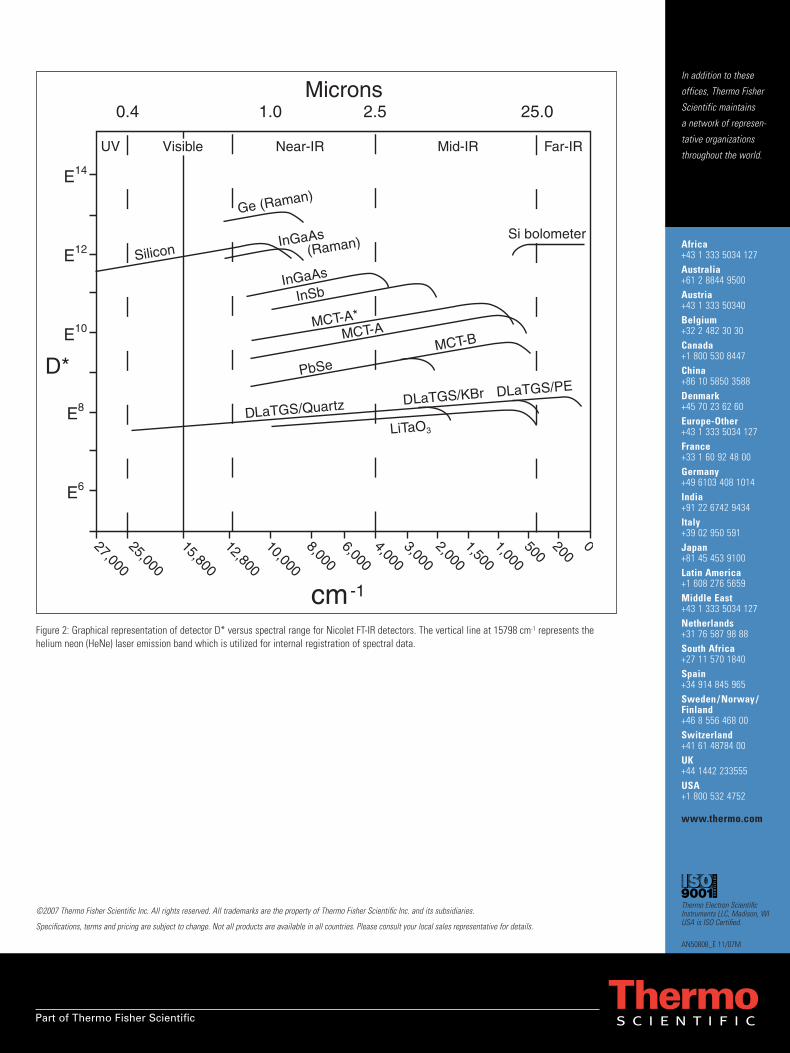
Figure 2: Graphical representation of detector D* versus spectral range for Nicolet FT-IR detectors. The vertical line at 15798 cm-1 represents the helium neon (HeNe) laser emission band which is utilized for internal registration of spectral data.
In addition to these
offices, Thermo Fisher
Scientific maintains
a network of represen-
tative organizations
throughout the world.
Africa+43 1 333 5034 127Australia+61 2 8844 9500Austria+43 1 333 50340Belgium+32 2 482 30 30Canada+1 800 530 8447China+86 10 5850 3588Denmark+45 70 23 62 60 Europe-Other+43 1 333 5034 127France+33 1 60 92 48 00Germany+49 6103 408 1014India+91 22 6742 9434Italy+39 02 950 591Japan +81 45 453 9100Latin America+1 608 276 5659Middle East+43 1 333 5034 127Netherlands+31 76 587 98 88South Africa+27 11 570 1840Spain +34 914 845 965Sweden / Norway /Finland+46 8 556 468 00Switzerland+41 61 48784 00UK +44 1442 233555USA +1 800 532 4752
www.thermo.com
AN50808_E 11/07M
Thermo Electron ScientificInstruments LLC, Madison, WIUSA is ISO Certified.
Part of Thermo Fisher Scientific
©2007 Thermo Fisher Scientific Inc. All rights reserved. All trademarks are the property of Thermo Fisher Scientific Inc. and its subsidiaries.
Specifications, terms and pricing are subject to change. Not all products are available in all countries. Please consult your local sales representative for details.