Embed Size (px)
Citation preview
©JBS&G Australia Pty Ltd T/A Strategen-JBS&G www.jbsg.com.au | ABN 62 100 220 479
CWD response to RFI January 2021
3 February 2021
Regulatory Services Department of Water and Environmental Regulation Via email: [email protected]
APPLICATION FOR A WORKS APPROVAL UNDER THE ENVIRONMENTAL PROTECTION ACT 1986 – REQUEST FOR FURTHER INFORMATION
Further to your letter dated 24 November 2020, please find attached Controlled Waste Disposals’ (CWD) response (Table 1) to the request for further information in Schedule 1 of your letter.
If you require any further information, please do not hesitate to CWD on 08 9380 3100 or by email [email protected].
Yours sincerely:
Principal Strategen-JBS&G

CWD response to RFI January 2021
©JBS&G Australia Pty Ltd T/A Strategen-JBS&G www.jbsg.com.au | ABN 62 100 220 479
Table 1: Response to Schedule 1 Information requirements
Specifications (including professional accreditation requirements)
Rationale Response
Part 9.1 and 9.3 – Potential emissions and discharges from proposed activities
The application mentions the installation and commissioning of fire protection systems, fire detection and alarm systems, and fire suppression systems. However, further information regarding these systems is not provided. Given the fire risks associated with the storage of numerous hazardous waste types, further information is required to adequately assess whether the applicant controls will adequately manage the risks associated with fire. A Fire and Emergency Management Plan (FEMP) should be prepared and submitted in accordance with Australian Standard 3745:2010 Planning for Emergencies. As a minimum the plan must include: • Assessment of fire safety risk including identification of
areas where a fire might occur and conditions which might lead to a fire.
• Fire prevention measures. This should include the range of infrastructure/equipment, process and management controls used to reduce the risk of fires at the premises. Examples include waste storage and segregation requirements (appropriate labelling and compatible waste storage requirements), stockpile separation distances, ignition source identification/elimination and security measures to mitigate the risk of arson.
• Fire control and response measures. This should include the range of infrastructure/equipment, process and management measures. Please provide details of the firefighting infrastructure currently onsite, and any further firefighting infrastructure proposed to be installed as part of the application. Firefighting infrastructure may include firefighting hoses/sprinklers, water supply planning, detection and alarms and firewater containment. Management procedures in the event of a fire, including personnel responsibilities, are also required.
Further information is required to adequately assess whether the applicant controls will adequately manage the risks associated with fire.
CWD has appointed an independent consultant to prepare a FEMP for the proposed facility. Given this is a new requirement with no specific DWER guidance available, CWD requires additional time to prepare the documents. It is estimated that the plan will be submitted to DWER by the end of February 2021. CWD requests that DWER considers if it can validate the application pending the submission of the FEMP so that the fee can be paid, and the advertising period commenced. CWD accepts that the application would go on stop-the-clock post payment of the application fee until the FEMP is provided.

CWD response to RFI January 2021
©JBS&G Australia Pty Ltd | www.jbsg.com.au | ABN 62 100 220 479 3
Information requirements
Specifications (including professional accreditation requirements)
Rationale Response
Part 9.1 and 9.3 – Potential emissions and discharges from proposed activities
Table 7.6 of the Supporting information document (JBS&G Australia Pty Ltd, November 2020) states, in relation to odour, that vents from tanks are to be ducted to emissions control system prior to emission to atmosphere, and tanker vents to be connected to storage tank during loading to create a closed loop. It is unclear whether the tanks specified include the external tank farm, or whether the controls only relate to the internal storage tanks. Please provide confirmation of the odour controls relating to the external tank farm, and whether they are to be connected to the carbon filtration system.
Further information is required to adequately assess whether the applicant controls will adequately manage the risks associated with odour.
The reference to tanks in Table 7.6 of the supporting information document is to the external tank farm. Vents on the external tanks will be connected to the carbon filtration system.
Part 9.1 and 9.3 – Potential emissions and discharges from proposed activities
The application states that the waste receivals area includes the tanker washdown area with resulting wastewater drained to a bunded area and mixed with sawdust for disposal. It is unclear from this description where exactly tanker and container washing occurs. Please confirm if container and tanker washing occurs in Area M (solid treatment area).
Further information is required to adequately assess whether the applicant controls will adequately manage the risks associated with odour and leachate.
Tanker and ISO container wash out will occur in Area M.
Part 9.1 and 9.3 – Potential emissions and discharges from proposed activities
The application refers to the use of an activated carbon filtration unit within the main building to reduce odour emissions. DWER acknowledges that the filter dimension will be designed to allow minimum empty bed residence time of three seconds at maximum flow rate, the design flow rate will be 3000 m3/hr and the unit will achieve at least a 90% reduction in odour concentration and VOC concentration. DWER wishes to clarify whether the specific filtration unit has been selected or whether the design is conceptual. To assess the adequacy of the filtration unit, further information relating to the manufacturer specifications of the system should be provided, including the appropriate maintenance schedule of the system.
Further information is required to adequately assess whether the applicant controls will adequately manage the risks associated with odour.
The design of the activated carbon filtration unit is conceptual but will be based on the unit currently in use at CWD’s existing facility. Performance verification and ongoing maintenance of the unit will be carried out as described in Section 6.1.2 of the supporting information document.
CWD response to RFI January 2021
©JBS&G Australia Pty Ltd | www.jbsg.com.au | ABN 62 100 220 479 4
Information requirements
Specifications (including professional accreditation requirements)
Rationale Response
Part 9.1 and 9.3 – Potential emissions and discharges from proposed activities
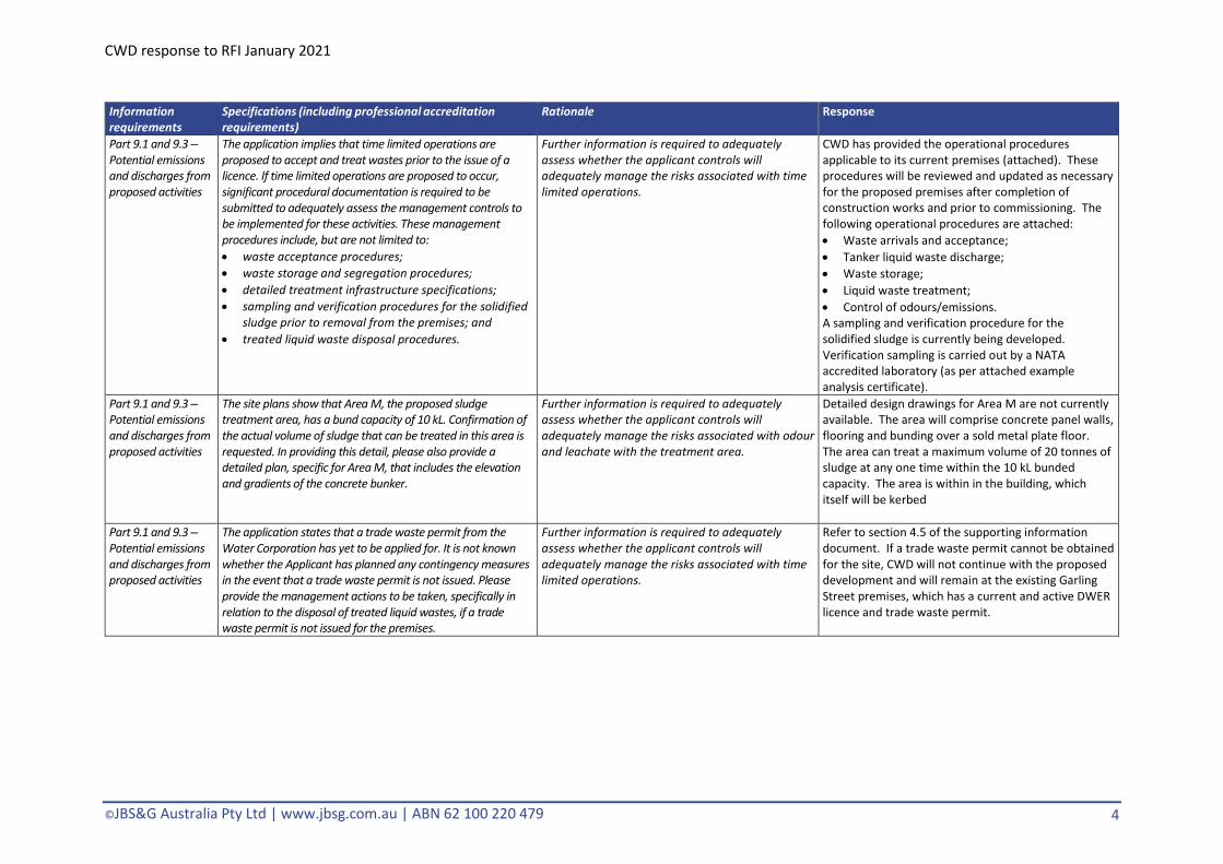
The application implies that time limited operations are proposed to accept and treat wastes prior to the issue of a licence. If time limited operations are proposed to occur, significant procedural documentation is required to be submitted to adequately assess the management controls to be implemented for these activities. These management procedures include, but are not limited to: • waste acceptance procedures; • waste storage and segregation procedures; • detailed treatment infrastructure specifications; • sampling and verification procedures for the solidified
sludge prior to removal from the premises; and • treated liquid waste disposal procedures.
Further information is required to adequately assess whether the applicant controls will adequately manage the risks associated with time limited operations.
CWD has provided the operational procedures applicable to its current premises (attached). These procedures will be reviewed and updated as necessary for the proposed premises after completion of construction works and prior to commissioning. The following operational procedures are attached: • Waste arrivals and acceptance; • Tanker liquid waste discharge; • Waste storage; • Liquid waste treatment; • Control of odours/emissions. A sampling and verification procedure for the solidified sludge is currently being developed. Verification sampling is carried out by a NATA accredited laboratory (as per attached example analysis certificate).
Part 9.1 and 9.3 – Potential emissions and discharges from proposed activities
The site plans show that Area M, the proposed sludge treatment area, has a bund capacity of 10 kL. Confirmation of the actual volume of sludge that can be treated in this area is requested. In providing this detail, please also provide a detailed plan, specific for Area M, that includes the elevation and gradients of the concrete bunker.
Further information is required to adequately assess whether the applicant controls will adequately manage the risks associated with odour and leachate with the treatment area.
Detailed design drawings for Area M are not currently available. The area will comprise concrete panel walls, flooring and bunding over a sold metal plate floor. The area can treat a maximum volume of 20 tonnes of sludge at any one time within the 10 kL bunded capacity. The area is within in the building, which itself will be kerbed
Part 9.1 and 9.3 – Potential emissions and discharges from proposed activities
The application states that a trade waste permit from the Water Corporation has yet to be applied for. It is not known whether the Applicant has planned any contingency measures in the event that a trade waste permit is not issued. Please provide the management actions to be taken, specifically in relation to the disposal of treated liquid wastes, if a trade waste permit is not issued for the premises.
Further information is required to adequately assess whether the applicant controls will adequately manage the risks associated with time limited operations.
Refer to section 4.5 of the supporting information document. If a trade waste permit cannot be obtained for the site, CWD will not continue with the proposed development and will remain at the existing Garling Street premises, which has a current and active DWER licence and trade waste permit.

CWD response to RFI January 2021
©JBS&G Australia Pty Ltd | www.jbsg.com.au | ABN 62 100 220 479 5
Information requirements
Specifications (including professional accreditation requirements)
Rationale Response
Part 9.1 and 9.3 – Potential emissions and discharges from proposed activities
The application includes Category 57: Used tyre storage for 500 tyres. The application has not however, provided detailed information regarding the storage and processing of these tyres, other than generic information regarding storage and processing location. Further detailed information is required regarding the tyre storage location, associated infrastructure specifications, detail regarding tyre storage configuration (stack sizes and separation distances), as well as proposed separation distances between tyres stacks and other wastes on the premises. In responding to this request, consideration should be given to the DFES Guidance Note GN02: Bulk Storage of Rubber Tyres Including Shredded and Crumbed Tyres.
Further information is required to adequately assess whether the applicant controls will adequately manage the risks associated with tyre storage.
CWD only intend to store tyres associated with the maintenance of its vehicles on the premises. CWD will not accept and store waste tyres at the premises and requests that Category 57 and the tyre storage aspect is removed from the application.
Part 4.9 - Estimated / actual throughput for each category applied for
The application includes Category 61A: Solid waste facility for 5000 tonnes per year. It is unclear what wastes will be accepted under category 61A. Further information is required in relation to category 61A activities and quantities of solid wastes proposed to be accepted, stored and treated.
Further information is required to adequately assess the necessary categories for the premises.
Refer to Table 5.5 of the supporting information document for the description of solid waste types, quantities, acceptance, treatment and disposal. Solid wastes will be limited to Category N wastes – N100 (containers and drums) and N120 (contaminated soils).
Part 2.7 - Occupier status
The application states that lease information will be provided at a later date. It is noted that the assessment cannot be finalised until this information is submitted to the department.
Information relating to the occupier status of the proposed activities is required for the assessment of the works approval.
A copy of the lease will be provided to DWER prior to the finalisation of the assessment.
Part 7.5 – Planning approval
The application states that an application for Development Approval will be submitted to the City of Cockburn on validation of the works approval application to ensure consistency in information provided. It is requested that proof of the submission of this development application is submitted to the department once completed (i.e. post validation of the application).
Information relating to planning status of the proposed activities is required to finalise the assessment of the works approval.
Application for development approval was submitted to the City of Cockburn on 28 January 2021 (reference number DA21/0093).

CWD response to RFI January 2021
©JBS&G Australia Pty Ltd | www.jbsg.com.au | ABN 62 100 220 479 6
Attachment A: Operational procedures

1
Controlled Waste Disposals (CWD)
Master DWER Compliance Procedure-Waste Liquids Receivals
Preamble-CWD Services CWD is the service provider to the DWER Licensee, for compliant liquid waste services operations, at the Licenced premised location.
Licence number L8730/2013/1 Licence holder Fremantle Plumbing Service Pty Ltd ACN Registered business address
DWER file number Duration 27/03/2013 to 26/03/2022 Date of issue 8 June 2020 Premises details Fremantle Plumbing Services
107 Garling Street O’CONNOR WA 6163
Legal description - Lot 138 on Deposited Plan 6759 Certificate of Title Volume 1276 Folio 970
L8730/2013/1 (amended 8 June 2020)
Table 1 Types of Wastes authorised to be accepted onto the premises
Table 1: Types of waste authorised to be accepted onto the premises Waste type1
Waste Code Rate at which waste is received
Acceptance specification
Acids B100 Combined total up to 40,950 tonnes per annual period.
Tankered into the premises or delivered in intermediate bulk containers (IBC), drums or other containers.
Alkalis C100 Paints and resins F100 Oils J100, J120, J130, J180 Industrial wash water L100

2
Non halogenated organic chemicals (engine coolants)
M130
Surfactants and detergents (wetting agents and emulsifiers)
M250
Drilling mud N120
L8730 Licence.pdf
2 Pre-acceptance requirements From 2 months from the date of issue of this licence, prior to the acceptance of any liquid waste stream at the premises, the licence holder must ensure that: (a) information on the characteristics of the waste is obtained; and
(b) a suitably qualified chemistry technician assesses the information obtained in accordance with condition 2(a) above and determines whether the waste can be treated, solidified, or stored at the premises to meet the requirements of this licence. 3 Waste receipt The licence holder must ensure that, with the exception of oil waste types, all liquid waste streams are subject to verification testing by a suitably qualified chemistry technician upon arrival to confirm that: (a) the characteristics of each liquid waste stream is consistent with the details obtained in accordance with condition 2 for that waste; and
(b) the liquid waste stream is suitable for the proposed treatment, solidification and/or storage process determined in accordance with condition 2. 4. The licence holder must ensure that, with the exception of oil waste types, wastes accepted in containers smaller in size than an IBC are: (a) accompanied by a written description of the contents of each container; (b) appropriately labelled to match the written description required by sub-provision (a);
(c) subject to verification testing by a qualified chemist to confirm that the waste is consistent with the accompanying written and labelled description; and
(d) subject to verification testing by a qualified chemist to determine whether the waste is suitable for treatment, solidification and/or storage at the premises.
(a) held in a dedicated receipt area with the infrastructure specified in Row 3 of Table 3, pending confirmation of their acceptability; and
(b) stored in manner that ensures incompatible wastes are unable to mix. 5. The licence holder must ensure that all wastes undergoing verification testing required by conditions 3 and 4 are:
(a) held in a dedicated receipt area with the infrastructure specified in Row 3 of Table 3, pending confirmation of their acceptability; and (b) stored in manner that ensures incompatible wastes are unable to mix.

3
6. The licence holder must ensure that waste is not accepted onto the premises unless sufficient treatment, solidification or storage capacity exists for that waste and the site is adequately manned to receive the waste to ensure the requirements of this licence are met.
Preamble – General
Wastes shall not be accepted at the installation, without costings, a clear, defined method of handling, processing, disposal, being determined, inclusive of sufficient temporary storage capacity available. These checks shall be performed before the waste acceptance stage is reached.
As operator, CWD shall ensure that the installation personnel who may be involved in the sampling, checking and analysis procedures are suitably qualified/competent, (a suitably qualified chemistry technician or higher) adequately trained, and that the training is updated on a regular basis.
Analysis shall be carried out by laboratory calibrated instruments, or similar, by various means applicable, with suitably accredited test methods. (see lab testing equipment available)
Samples shall be retained on-site for a minimum of two days after the waste has been treated, and/or removed off-site, including all residues from its treatment.
All waste received in Containers such as IBC’s/Drums etc shall be Labelled
Once analysis has confirmed that the waste is acceptable, the Operator shall only then, create a batch for treatment. Once a batch has been assembled for treatment, the operator shall confirm the applicable composite sample availability/analysis, prior to treatment. Scope of analysis depends upon the intended treatment, and should be specified.
Heavy sludge, and solids at the facility that cannot process shall be spaded, and once deemed inert, removed from the facility to a licenced land fill location
There shall be a clear distinction between sales, technical staff, their roles, and responsibilities. If non-technical sales staff are involved in waste enquiries, then a final technical assessment, prior to approval shall be made.
It is this final technical checking that shall be used to avoid build-up of accumulations of wastes, and to ensure that sufficient capacity exists.
4
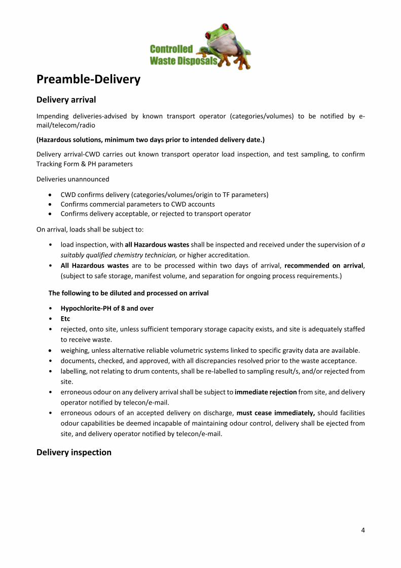
Preamble-Delivery
Delivery arrival
Impending deliveries-advised by known transport operator (categories/volumes) to be notified by e-mail/telecom/radio
(Hazardous solutions, minimum two days prior to intended delivery date.)
Delivery arrival-CWD carries out known transport operator load inspection, and test sampling, to confirm Tracking Form & PH parameters
Deliveries unannounced
• CWD confirms delivery (categories/volumes/origin to TF parameters) • Confirms commercial parameters to CWD accounts • Confirms delivery acceptable, or rejected to transport operator
On arrival, loads shall be subject to:
• load inspection, with all Hazardous wastes shall be inspected and received under the supervision of a suitably qualified chemistry technician, or higher accreditation.
• All Hazardous wastes are to be processed within two days of arrival, recommended on arrival, (subject to safe storage, manifest volume, and separation for ongoing process requirements.)
The following to be diluted and processed on arrival
• Hypochlorite-PH of 8 and over • Etc • rejected, onto site, unless sufficient temporary storage capacity exists, and site is adequately staffed
to receive waste. • weighing, unless alternative reliable volumetric systems linked to specific gravity data are available. • documents, checked, and approved, with all discrepancies resolved prior to the waste acceptance. • labelling, not relating to drum contents, shall be re-labelled to sampling result/s, and/or rejected from
site. • erroneous odour on any delivery arrival shall be subject to immediate rejection from site, and delivery
operator notified by telecon/e-mail. • erroneous odours of an accepted delivery on discharge, must cease immediately, should facilities
odour capabilities be deemed incapable of maintaining odour control, delivery shall be ejected from site, and delivery operator notified by telecon/e-mail.
Delivery inspection

5
Visual inspection safety checks shall be carried out on all transport, both bulk and packaged cargoes safety prior to directing transport operator to proceed to offloading dock. (Further inspection shall be carried out during discharge of all bulks into dedicated sampling/discharge bay)
Mandatory checks, for packaged containers to confirm quantities to Tracking Form documentation. Containers to be clearly labelled and equipped with well-fitting lids, caps, any valves secure. Damaged, corroded and/or unlabelled drums shall be rejected and/or placed into a quarantine area, and dealt with appropriately.
Mandatory labelling for each container, the CWD tracking reference number/date of arrival, TF no, and primary hazard code, to be applied to each container.
Where containers are bulked, the earliest date of arrival of the bulked wastes should be transposed from the original container onto the bulk container.
All CWD inspection, unloading, and sampling areas shall have suitably sealed drainage systems, and marked on a plan.
Should the inspection, or analysis indicate that the wastes fail to meet the acceptance criteria (including damaged or unlabelled drums), then such loads shall be stored in a dedicated quarantine area and dealt with appropriately. Such storage shall be for a maximum of five working days.
Written procedures should be in place for dealing with wastes held in quarantine, together with a maximum storage volume.
Should the cause of failure to meet acceptance criteria is due to incompatibility, then the wastes shall be segregated immediately to remove the hazard.
Delivery verification
Tanker, bulk liquid wastes, shall be sampled prior to acceptance. There shall be no storage pending sampling.
On-site verification and compliance testing should take place to confirm:
• the identity of the waste
• the description of the waste
• consistency with pre-acceptance information and proposed treatment method
• compliance with permit
Delivery rejection
The CWD Operator shall has clear and unambiguous criteria for the rejection of wastes, together with a written procedure for tracking, and reporting such non-conformance. This should include notification to the customer/waste producer, and the Regulator.
Written/computerised records should form part of the waste tracking system information.
Acceptance of laboratory chemicals

6
The procedure for accepting laboratory chemicals on-site shall be essentially identical to that for drummed waste. They differ from the “normal” waste inputs to site in that they are in a pure concentrated form.
In situations where the Transport Operator has undertaken the identification, and packaging, on behalf of the customer, then the on-site verification can be restricted to opening the drums to check that the containers remain undamaged.
In such cases the load must be accompanied by documentation confirming the checking and packing. In situations where the drum has been packed by the customer, then full checking and verification should be undertaken.
Checking packaging and segregation adequately shall include emptying of the drum as soon as possible, and in any event at facilities that are operated 24 hours a day, within 24 hours.
At sites not operated around the clock, checking must be undertaken before the end of the working day. Repack- aging the waste must be undertaken as soon as the necessary checks have been undertaken.
Waste Rejection
Lab smalls must not be accepted at a facility where there are insufficient suitably qualified personnel to process these wastes within the above timescales
If on opening a drum it is found that it contains incompatible substances, or that the substances have not been packaged adequately, then the drum shall be sorted and repacked immediately, and the non-conformance procedure followed.
Sorting and repackaging of laboratory chemicals shall take place in a dedicated area/store. Once the wastes have been sorted according to hazard classification, with consideration for any potential incompatibility problems, and repacked, then these drums, shall not be stored within the dedicated laboratory chemicals area but shall be removed to the appropriate storage area.
The CWD operator shall have clear and unambiguous criteria for the rejection of wastes, together with a written procedure for tracking, and reporting such non-conformance.
This shall include notification to the customer/waste producer, and the Environment Agency.
Written/computerised records shall form part of the waste tracking system information. The operator shall also have a clear and unambiguous policy for the subsequent storage and disposal of such rejected wastes.
This policy shall achieve the following:
• identifies the hazards posed by the rejected wastes
• labels rejected wastes with all information necessary to allow proper storage, and segregation arrangements to be put in place
• segregates, and stores rejected wastes safely pending removal
Immediate rejection of foreign products such as.
• Damaged packaging / containers • Pressure cylinders/tanks of any kind (fire extinguishers/gas cylinders etc)
7
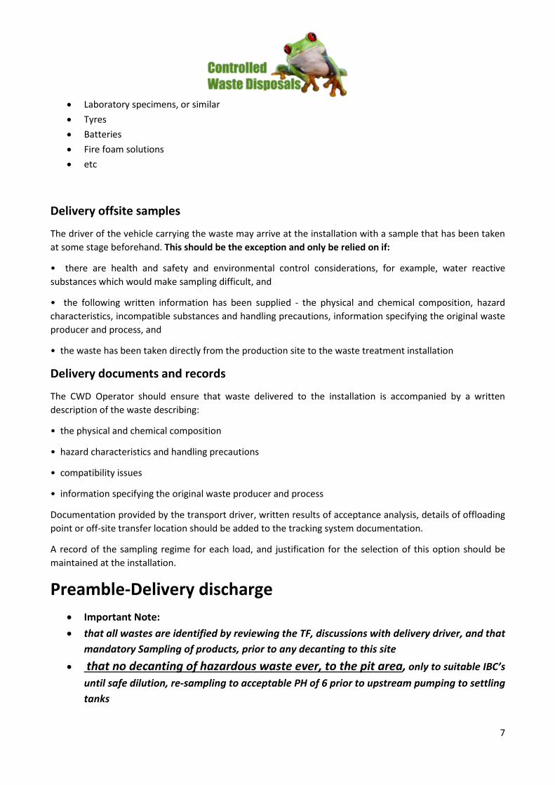
• Laboratory specimens, or similar • Tyres • Batteries • Fire foam solutions • etc
Delivery offsite samples
The driver of the vehicle carrying the waste may arrive at the installation with a sample that has been taken at some stage beforehand. This should be the exception and only be relied on if:
• there are health and safety and environmental control considerations, for example, water reactive substances which would make sampling difficult, and
• the following written information has been supplied - the physical and chemical composition, hazard characteristics, incompatible substances and handling precautions, information specifying the original waste producer and process, and
• the waste has been taken directly from the production site to the waste treatment installation
Delivery documents and records
The CWD Operator should ensure that waste delivered to the installation is accompanied by a written description of the waste describing:
• the physical and chemical composition
• hazard characteristics and handling precautions
• compatibility issues
• information specifying the original waste producer and process
Documentation provided by the transport driver, written results of acceptance analysis, details of offloading point or off-site transfer location should be added to the tracking system documentation.
A record of the sampling regime for each load, and justification for the selection of this option should be maintained at the installation.
Preamble-Delivery discharge
• Important Note: • that all wastes are identified by reviewing the TF, discussions with delivery driver, and that
mandatory Sampling of products, prior to any decanting to this site • that no decanting of hazardous waste ever, to the pit area, only to suitable IBC’s
until safe dilution, re-sampling to acceptable PH of 6 prior to upstream pumping to settling tanks

8
• that, no odours (residential area) to atmosphere is acceptable---ever • of the importance of Ventilation in task areas, at, all times, and appropriate PPE thereof • Under direction of CWD operators • CCTV surveillance • Via sediment drop box, and floatation offtake box. • Heavy sludge to pit • Photographic record as required • Transport wash-down
Wastes not be deposited within a reception area/s without adequate space.
Appropriate storage shall be achieved, immediately upon offloading.
Wastes in containers, shall be unloaded into a dedicated reception area pending acceptance sampling. Such storage shall be for a maximum period of 5 days.
During this period, there shall be no bulking up, or mixing of drums, or decanting the contents into bulk storage. Wastes shall be stored within this reception area according to compatibility in line with HSE Guidance Note HSG71.
Dangerous Good Solutions discharge
• Operations Manager notified, and in attendance • TF to be reviewed and discussed with driver • JSEA to be actioned with all participants signing off JSEA • Locate structurally sound, suitable flushed, and pre-labelled 1000 litre IBC’s. • Allow contingency of extra IBC volume, to the TF Volume • Appropriate segregation of offload area • Applicable PPE • On completion of acceptable sampling, decant only maximum of 900 litres of solution into each IBC,
thus allowing minimum 100 litres void for direct dilution purposes • Seal IBC’s on each fill and washdown all with water on completion
Light viscosity discharge
• To appropriate storage settling tank/s • (PH below 7 to Tank 1, above 7 to tank 2/3)
Heavy viscosity discharge
• To appropriate storage settling tank/s (PH below 7 to Tank 3/4, above 7 to tank 1/2)
Hydrocarbon discharge
• Al hydrocarbon receivables subject to hydrocarbon percentage, decant to the Hydrocarbon day tank/s, and or, applicable storage settling tank/s

9
Tracking form signoff
• CWD signoff, copy to transport operator • TF details, and photographic evidence to CWD operations data base • TF to DWER data base file, TF hard copy DWER archive file
Pit discharge sludge
• On pit drain off, to spading nests for further liquid filtering • Eventual spading • Eventual Bin transfer to landfill
Hydrocarbon Offtake
• All settling tanks, and oily water separator discharges, to be transferred to hydrocarbon day tank storage, with daily water drain off to day tank sump, recycling to storage settling tanks
• All hydrocarbon offtake from hydrocarbon day tank/s storage, shall be by registered recyclers licenced road tanker
Records
The waste tracking system shall hold all the information generated during pre-acceptance, acceptance, storage, treatment and/or removal off-site.
Records shall be made and kept up to date on an ongoing basis to reflect deliveries, on-site treatment, and despatches. The tracking system shall operate as a waste inventory/stock control system and include as a minimum:
• date of arrival on-site
• producer’s details
• all previous holders
• a unique reference numbers
• pre-acceptance and acceptance analysis results
• package type and size
• intended treatment/disposal route
• record accurately the nature and quantity of wastes held on site, including all hazards, and identification of primary hazards
• where the waste is physically located in relation to a site plan
• where the waste is in the designated disposal route
• identification of operator’s staff who have taken any decisions re acceptance, or rejection, of waste streams and decided upon recovery / disposal options

10
All records relating to pre-acceptance shall be maintained and kept readily available at the installation for cross-reference and verification at the waste acceptance stage.
Records shall be held for a minimum of two years after the waste has been treated or removed off-site.
Records shall be held in an area well removed from hazardous activities to ensure their accessibility during any emergency.
The system adopted shall be capable of reporting for all the following:
• total quantity of waste present on-site at any one time, in appropriate units, for example, 205 litre drum equivalents
• breakdown of waste quantities being stored pending on-site treatment, classified by treatment route
• breakdown of waste quantities on-site for storage only, that is, awaiting onward transfer
• breakdown of waste quantities by hazard classification
• indication of where the waste is located on site relative to a site plan
• comparison of the quantity on site against total permitted
• comparison of time the waste has been on-site against permitted limit
These records shall be held in a designated area, as agreed with the Agency, well removed from hazardous activities to ensure their accessibility during any emergency
Back-up copies of computer records shall be maintained off-site.
Preamble-Receivals Sampling - Testing
Sampling - Testing
Other than pure product chemicals and laboratory chemicals, no wastes shall be accepted at the installation without sampling, checking, and testing being carried out. Reliance solely on the written information supplied is not acceptable, with physical verification, analytical confirmation, required. All wastes, whether for on-site treatment, or temporary storage, must be sampled, undergo verification, and compliance testing.
The installation shall have a designated sampling point, or reception area. These shall be in close but safe proximity to the laboratory/checking facility, with the sampling point being visible (or covered by CCTV), if sampling is not directly supervised by, for example, laboratory staff.
The offloading, sampling point/reception, and quarantine areas shall have an impervious surface with self-contained drainage, to prevent any spillage entering the storage systems or escaping off-site. Most spills and leaks during sampling are on a small scale, resulting from releases from the tanker sample line, or back valve of a tanker, if the sample is being obtained in this way.
Attention shall be given to ensuring that incompatible substances do not come into contact resulting from spills from sampling, for example, within a sump serving the sampling point. Absorbents shall be made available.
Sampling of bulk liquid wastes

11
Deliveries in bulk road tanker should be accompanied by a “wash-out” certificate, or a declaration of the previous load so that contamination by this route can be checked.
Samples are usually taken by the tanker driver, witness by the CWD onsite Chemist from one of three points on the tanker:
• top hatch
• sampling line
• back valve
• sight glass
A gantry should be used to avoid the need to take samples from the back valve of tankers, which is likely to result in a small spillage.
CWD Onsite Chemist shall:-
• On review of Tracking form parameters, along with discussion with delivery driver, onsite chemist/driver utilising appropriate PPE, shall retrieve each individual bulk delivery sample
• Label delivery collected sample with tracking form number/date • Confirm sample PH level, Zinc concentration, Brix (glycol), and specific gravity of sample, etc • Update label with test results • Provide CWD process operators/Driver of sample results • Record above to Tracking form running spread sheet • Labelling not applicable for bulk tanker deliveries
CWD Process operators:-
• Confirm applicable/compatible, discharge procedure to delivery sample parameters, and appropriate PPE thereof
• Confirm discharge location (pit, and or process upstream to tank farm applicable) • Direct driver as applicable for safe discharge, connect liquid discharge hose • Remove discharge hose on completion of bulk liquid discharge • Direct driver for further sludge removal from tanker as applicable • Report viscosity/parameters of sludge discharged/volumes for Tracking form signoff
Delivery driver shall:-
• Operate discharge valve (controlled) on instruction from process operator • Close liquids discharge valve on instructions from process operator • On removal of discharge hose, and as applicable, open rear discharge hatch for removal of heavy
sludge • Wash out tank and hose down truck • Collect Tracking form and safely egress from site
Sampling IBC/drummed waste

12
The contents can only be identified with certainty if every container is sampled. Acceptance shall involve sampling every container. However, analysis of composite samples is acceptable with such a sampling regime. A representative sample must be obtained by taking a core sample to the base of the container. Operators should ensure that lids, bungs, and valves are replaced immediately after sampling.
CWD Onsite Chemist shall:-
• On review of Tracking form parameters, along with discussion with delivery driver, onsite chemist/driver utilising appropriate PPE, shall retrieve each individual bulk delivery sample
• Label delivery collected sample with tracking form number/date • Confirm sample PH level, Zinc concentration, Brix (glycol), and specific gravity of sample, etc • Update label with test results • Provide CWD process operators/Driver of sample results • Record above to Tracking form running spread sheet • Labelling applicable for all IBC/Drum deliveries
CWD Process operators:-
• Confirm applicable/compatible, discharge procedure to delivery sample parameters, and appropriate PPE thereof
• Driver to release tiedowns • Confirm discharge location/separation • Ensure all valves and lids sealed • Report volumes for Tracking form sign-off
Delivery driver shall:-
• Tiedown/sheet out truck • Wash/hose down truck as applicable • Collect Tracking form and safely egress from site
IBC/Drum Labelling
For drummed waste, controls shall ensure each drum is given a unique label to facilitate a record of:
• the location of each drum
• the duration of storage
• the chemical identity of the drum contents
• the hazard classification for each drum
Drums shall be handled, and stored, so that the label is readily visible
CWD Onsite Chemist shall:-
• Label all IBC/Drum deliveries, I.E. TF number, Date, Waste description/Code, carrier, applicable DG markings/segregation
• Record compatible temporary storage location
13
CWD Process operators:-
• Maintain compatible separation for drums and IBC’s
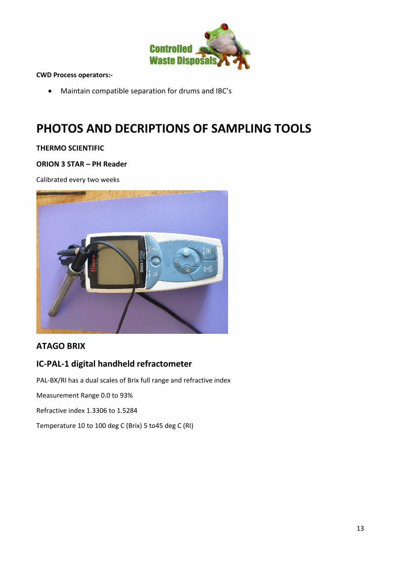
PHOTOS AND DECRIPTIONS OF SAMPLING TOOLS THERMO SCIENTIFIC
ORION 3 STAR – PH Reader
Calibrated every two weeks
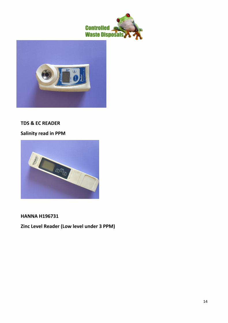
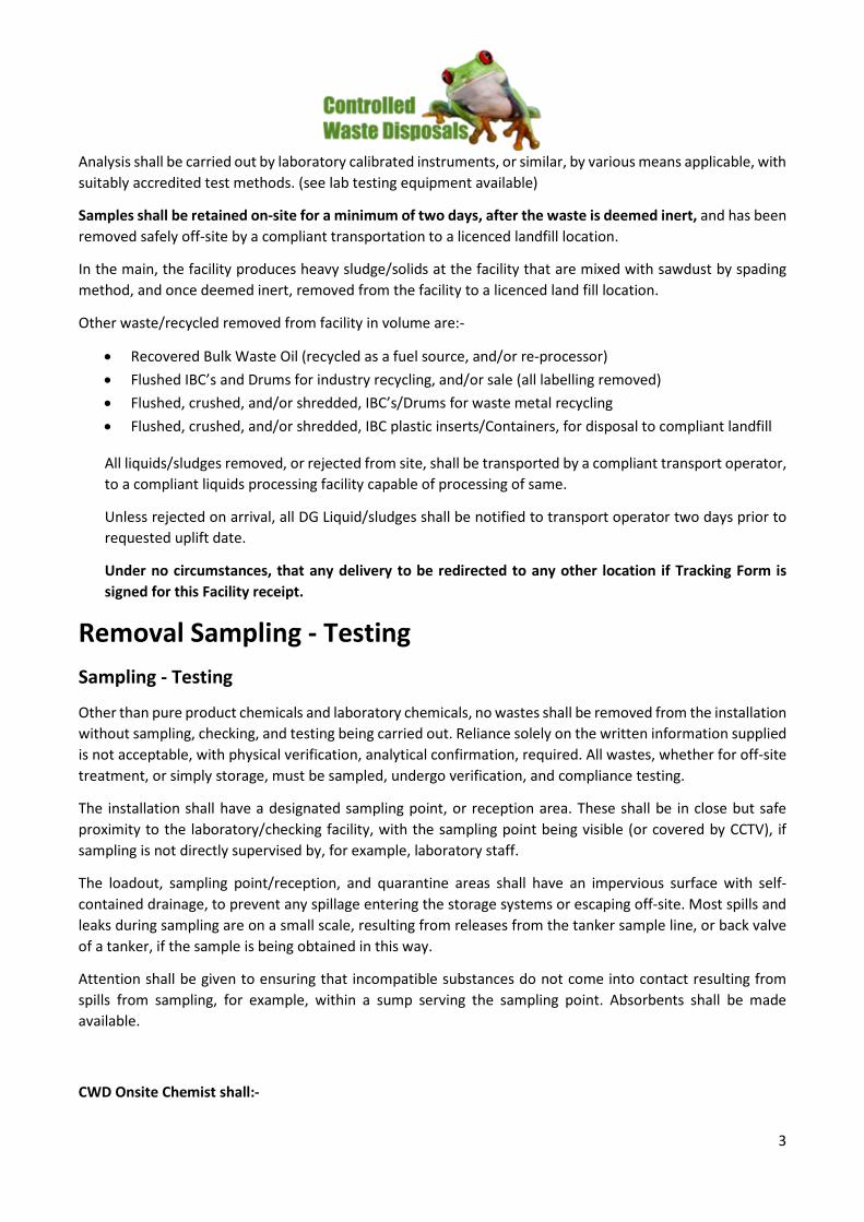
ATAGO BRIX
IC-PAL-1 digital handheld refractometer
PAL-BX/RI has a dual scales of Brix full range and refractive index
Measurement Range 0.0 to 93%
Refractive index 1.3306 to 1.5284
Temperature 10 to 100 deg C (Brix) 5 to45 deg C (RI)
14
TDS & EC READER
Salinity read in PPM
HANNA H196731
Zinc Level Reader (Low level under 3 PPM)

15
MACHEREY-NAGEL
Zinc Reader Litmus Strips (Higher levels 3 PPM +)
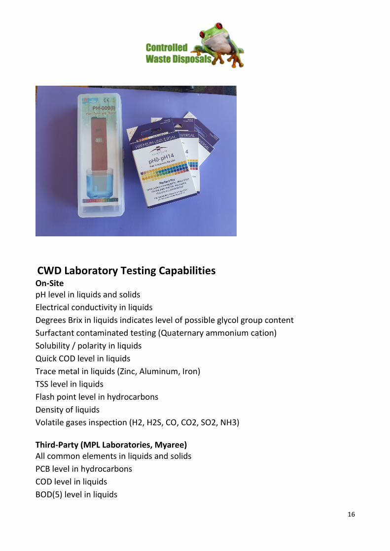
PREMIUM UNIVERSAL
Everyday Disposable PH Strips
16
CWD Laboratory Testing Capabilities On-Site pH level in liquids and solids Electrical conductivity in liquids Degrees Brix in liquids indicates level of possible glycol group content Surfactant contaminated testing (Quaternary ammonium cation) Solubility / polarity in liquids Quick COD level in liquids Trace metal in liquids (Zinc, Aluminum, Iron) TSS level in liquids Flash point level in hydrocarbons Density of liquids Volatile gases inspection (H2, H2S, CO, CO2, SO2, NH3) Third-Party (MPL Laboratories, Myaree) All common elements in liquids and solids PCB level in hydrocarbons COD level in liquids BOD(5) level in liquids

17
TOC level in liquids TPH level in liquids Moisture content in hydrocarbons CWD-SAFE SAFE WORKING PROCEDURES
• GENERAL EMERGENCY PROCEDURE • SAFE WORKING PROCEDURES– TANKERS AND BIN LIFTERS • SAFE WORKING PROCEDURES-FOR TANKER LIQUID WASTE DISCHARGE/INFLOW CIRCUIT (WASTE PIT
AREA OFFLOAD) • SAFE WORKING PROCEDURES-ODOURS • SAFE LOADING FOR SAFE OFFLOADING • SAFE WORKING PROCEDURES - FORKLIFTS • FORK TRUCK OPERATORS SAFETY CODE • TRAFFIC MANAGEMENT PLAN
CWD FEBRUARY 2021

Waste Storage
Offloading/discharge of waste
The Operator should have in place a system to ensure that the correct discharge point or
storage area is used. The options for this include:
• ticket systems
• supervision by site staff and if relevant CCTV
• keys
• colour-coded points/hoses or fittings of a specific size
Offloading and quarantine points should have an impervious surface with self-contained drainage, to prevent any spillage entering the storage systems or escaping off-site (see Section 2.8 on page 89).
Damaged hoses and connections must not be used.
Only couplings of the correct size for the connection should be used and the coupling should be able to withstand the maximum shut valve pressure of the transfer pump.
Record keeping
The Operator should have an internal tracking system which should satisfy the objectives and minimum standards given at Section 2.1.2 on page 25 for all wastes.
General storage requirements
Storage areas are often the most visible aspects of the installation. Storage areas should be located away from watercourses and sensitive perimeters, for example, those which may be adjacent to public rights of way, housing or schools, and within the security-protected area of the installation to prevent vandalism.
Storage areas should be located to eliminate or minimise the double handling of wastes within the installation.
Storage areas should be clearly marked and signed with regard to the quantity and hazardous characteristics of the wastes stored therein.
The total maximum storage capacity of the site should be clearly and unambiguously stated in writing, accompanied with details of the method used to calculate the volumes held against this maximum and set out in the site plan. The stated maximum capacity of storage areas should not be exceeded and the site plan updated to reflect any changes before they are implemented.
All containers should be clearly labelled with the date of arrival, relevant hazard code(s), chemical identity and composition of the waste and a unique reference number or code enabling identification through stock control and cross-reference to pre-acceptance and acceptance records. All labelling should be resilient enough to stay attached and legible throughout the whole time of storage at the installation.
Storage area drainage infrastructures should ensure that all contaminated run-off is contained, that drainage from incompatible wastes cannot come into contact with each other and that fire cannot spread between storage / treatment areas via the drainage system.
Procedures must be in place for the regular inspection and maintenance of storage areas, including drums, vessels, pavements and bunds. Inspections should pay particular attention to signs of damage, deterioration and leakage. Records should be kept detailing action taken. Faults must be repaired as soon as practicable. If containment capacity or capability of bund, sump or pavement is compromised, (unless effecting a repair is more expedient and working with wastes in close proximity does not compromise safety), then waste must be immediately removed until the repair is completed.
There should be daily inspection of the condition of containers and pallets and written records should be kept of these inspections. If a container is found to be damaged, leaking or in a state of deterioration, it should immediately be over-drummed or the contents transferred to another container or processed.
Over-drumming should be seen as an emergency measure and take place, if appropriate, in a designated location equipped with Local Exhaust Ventilation (LEV) as necessary. All appro- priate information should be transferred onto the label of the new container. Large quantities of wastes in over-drums should be avoided by re-drumming once the incident leading to over- drumming has been dealt with. Pallets damaged to the extent that the stability of the containers is or may become compromised should be replaced. “Plastic shrink wrap” should only be used to provide secondary stability to drum/container storage in addition to the use of sound pallets.
There should be vehicular, for example, forklift, and pedestrian access at all times to the whole of the storage area such that the transfer of containers is not reliant on the removal of others that may be blocking access, other than drums in the same row. Drums should not be stored on other drums more than two high and allow access for inspection on all sides. That is, four by 205 litre drums on a pallet, stacked no more than two by 205 litre drums high in rows.
All spillages of hazardous wastes should be logged, where spillages >200 litre then addition- ally the Regulator should be informed.
Activities that create a clear fire risk should not be carried out within the storage area, even if it is not formally classified as hazardous. Examples include grinding, welding or brazing of metal- work, smoking, parking of normal road vehicles except while unloading, charging of the batteries of fork lift trucks.
Turnover
Storage within the reception area should be for a maximum of five working days. Following receipt, wastes should be treated or removed off-site as soon as possible. The total storage time will depend upon the characteristics of a particular site and the waste types being stored. For example, on a site in a sensitive location handling hazardous wastes, it may be appropriate to limit storage times to one month. Other non-

hazardous wastes, however, may be held on-site for longer periods. However, all waste should be treated or removed off site within a maximum of six months from the date of receipt.
Storage of drummed waste and other containerised wastes such as IBCs
Storage under cover for drummed waste has the advantage of reducing the amount of potentially contaminated water that may be produced in the event of any spillage and extending the useful life of the container. It is preferable that wastes are stored under cover. This should also apply to any container that is held in storage pending sampling and emptied containers. Covered areas must have adequate provision for ventilation by means of wall or roof vents or construction of the area, for example, open barn. Any such warehousing should meet the requirements of HSG71 (see Ref 4).
Containers should be stored in such a manner that leaks and spillages could not escape over bunds/edge of the sealed drainage area.
Containers should be stored with well-fitting lids, caps and valves, secured and in place.
Storage areas for containers holding substances that are known to be sensitive to heat and light or reactive with water or moisture should be under cover and protected from water, heat and direct sunlight.
Storage areas for containers holding flammable or highly flammable wastes should meet the requirements of HSG 51, HSG71 and HSG76 (see Ref 4).
Aged stock
It is important to avoid accumulations of waste, which may in turn lead to a deterioration in the container resulting in spillage or, in extreme cases, the deformation of the container to such an extent that it cannot be moved.
Segregation
In addition to the requirements of this document, the segregation of wastes should meet the requirements of HSG71 and be justified by risk assessment.
HSG 71 provides no guidance on the use of fire walls to achieve separation or segregation of different types of waste in outdoor storage. Fire walls which are impervious to liquid, at least 2m high, and capable of withstanding an intense fire on one side without collapse, can be used to reduce the 3m separation required for some combinations of materials marked as ‘keep apart’. No more than two sides of a storage area should be provided with fire walls, because it would prevent good ventilation.

Storage of aerosols
Storage of aerosols should take place under cover in closed containers or cages. Aerosols should not be stored in open containers.
Storage of laboratory chemicals
Written procedures for the segregation and packing of laboratory chemicals should be produced identifying;
• How the hazards associated with each package are identified.
• How the risks of adverse reactions occurring between individual packages are assessed, and by whom.
• The level of competence, qualification and training required by those undertaking this assessment.
• How incompatible substances (i.e. those that could react to generate heat, fire or hazardous reaction products) are prevented from being stored within the same drum.
• How the wastes are to be packed and stored.
• How the wastes are to be recovered or disposed.
Incompatible substances should not be stored within the same drum.
Sorting and repackaging of laboratory chemicals should take place in a dedicated area/store.
Once the wastes have been sorted according to hazard classification, with due consideration for any potential incompatibility problems, and repacked, then these drums should not be stored within the dedicated laboratory chemicals area but should be removed to the appropriate storage area.
Compatibility testing
In order to prevent any adverse or unexpected reactions and releases before transfer involving the following activities, testing should take place prior to the transfer:
• tanker discharge to bulk storage
• tank-to-tank transfer
• transfer from container to bulk tank
• bulking into drums/IBCs
• bulking of solid waste into drums or skips
Any evolved gases and cause of odour should be identified. If any adverse reaction is observed, an alternative discharge or disposal route should be found.

Transfer from tanker, drums and other containers in bulk storage
Due consideration should be taken of the implications of scale-up from laboratory compatibility testing to bulk transfer and the Guidance is given in HSG143 (see Ref 4).
Wastes in containers should be transferred into storage vessels by dip pipe to minimise splash, fume and odour.
Transfer/discharge should only take place after compatibility testing has been completed and then only with the sanction of an appropriate manager. Approval should specify which batch/ load of material is to be transferred, the receiving storage vessel, equipment required, including spillage control and recovery equipment, and any special provisions relevant to that batch/load
During bulking to tankers, vapour balance lines connected to appropriate abatement equipment should be used.
Tankers must not be used as reaction vessels. Blending by bulking into tankers should only take place following a risk assessment and once suitable verification and compatibility testing has been carried out.
If flammable chemicals are being transferred, particular caution has to be taken to avoid the generation of static electricity, with the subsequent risk of ignition. Guidance on the safe use and handling of flammable liquids is provided by the Health and Safety Executive and is contained within HSG140, including Guidance on the issue of static electricity build-up. There may be other regulatory requirements to consider such as the Dangerous Substances and Explosive Atmospheres Regulations
A representative sample of the receiving tank/vessel/container should be mixed in a proportional ratio with a sample of incoming waste stream that it is proposed to add to the tank/ vessel/container. The two samples should take account of the “worst-case” scenario of likely constituents. The particular test parameters will be driven by the wastes being bulked. As a minimum, records of testing should be kept including any reaction giving rise to:
• increase in temperature
• viscosity change
• separation or precipitation of solids
• evolution of gases
• evolution of odours
Bulking up into drums(includes drum, tank, tanker or small container transfers into drums)
Bulking/mixing should only take place under instruction from and under direct supervision of a suitable manager/chemist and should be under Local Exhaust Ventilation (LEV) in appropriate cases. Odorous materials should not be bulked up. If bulking different batches, then a composite sample must be compatibility tested prior to bulking. Containers should be kept lidded/sealed as much as possible.

HSG 140 advises that gravity dispensing is avoided, unless physical protective devices are provided to prevent loss of the whole tanker contents.
Where tankers are discharged to drums, it must be possible to close the valve at the tanker
end quickly and safely in case of spillage. The valve at the dispensing end must close automatically if it is released. A minimum of two people will be needed for this operation or the operation of the tanker valve if access to the tanker valve is difficult.
Bulking of solid waste
Bulking of different batches must not take place without compatibility testing. In appropriate cases, LEV should be used to control odour and dust. Drums should be manipulated using mechanical means, for example, forklift with rotating drum handling fitting. Liquid waste must not be added to solid wastes other than in ‘purpose-designed and built’ reaction vessel, that is, decanting of liquids into a skip containing bulked solids must not take place.
Bulk storage vessels
Bulk storage vessels should be located on an impervious surface that is resistant to material being stored, with sealed construction joints within a bunded area with a capacity at least 110% of the largest vessel or 25% of the total tankage volume, whichever is the greater.
Vessels supporting structures, pipes, hoses and connections should be resistant to the substances (and mix of substances) being stored. There should be a routine programmed inspection of tanks, mixing and reaction vessels including periodic thickness testing. In the event of damage or significant deterioration being detected, the contents should be transferred to appropriate storage. These inspections should preferably be carried out by independent expert staff, and written records should be maintained of the inspection and any remedial action taken.
Vessels should not be used beyond the specified design life or used in a manner or for substances that they were not designed, Vessels should be inspected at regular intervals, with written records kept to prove that they remain fit for purpose. See HSE Guidance Note PM75.
As a general rule, no open-topped tanks, vessels or pits should be used for storage or treatment of hazardous or liquid wastes. Exceptions would require justification in the permit application.
No uncontrolled venting to atmosphere should be allowed, and all vents should be linked to suitable scrubbing and abatement systems. Vapour balance lines should be connected to suitable abatement systems.
Tank and vessel optimum design should be considered in each case, taking into account waste type, storage time, overall tank design and mixing system to prevent sludge accumulation and to ease desludging. Storage and treatment vessels should be regularly de-sludged.
Tanks and vessels should be equipped with suitable abatement systems and level meters with both audible and visual high-level alarms. These systems should be sufficiently robust and regularly maintained to prevent foaming and sludge build-up affecting the reliability of the gauges.

Storage vessels holding flammable or highly flammable wastes should meet the requirements of HSG51, HSG140, HSG716 and HSG176 (see Ref 4).
All connections between vessels must be capable of being closed via suitable valves. Overflow pipes should be directed to a contained drainage system, which may be the relevant bunded area, or to another vessel provided suitable control measures are in place.
Underground or partially underground vessels without secondary containment should be scheduled for replacement with above-ground structures, for example, double-skinned vessels with leakage detection.
Plant and equipment taken out of use should be decontaminated and removed.
Pipework should preferably be routed above ground; if below ground it should be contained within suitable inspection channels.
Silos should be equipped with dust abatement systems, level monitors and high-level alarms.
Storage bunkers should have extraction systems for particulate abatement or spray damping.
Tank & process pipework labelling
All vessels should be clearly signed as to their contents and capacity and should have a unique identifier. Tanks should be appropriately labelled.
Labelling should differentiate between wastewater and raw process water, combustible liquid and combustible vapour and direction of flow.
Written records of all tanks should be kept detailing:
• unique identifier
• capacity
• construction including materials
• maintenance schedules and inspection results
• fittings (including joints and gaskets etc.)
• waste types that may be stored/treated in the vessel including flashpoint limit
A suitable pipework coding system should be used, for example, RAL European standard colour coding.
All valves should be tagged with a unique identifier shown on the process and instrumentation diagram. All connections should be correctly sized and maintained in an undamaged state.

Other storage requirements
Waste or raw materials in non-waterproof packaging should be kept under cover.
Container movement
Drums and other mobile containers should only be moved between different locations (or loaded for removal off-site) in accordance with written procedures. The waste tracking system should then be amended to record these changes.

Liquid Waste Treatment
In-tank settlement and pre-treatment
Once received waste is been categorised and / or determined for treatment method. Settlement and pre-treatment shall take place before further processing, which are:
• Solid / hydrocarbon settlement
• Physical filtration
• Sharples centrifuge
• Electrocoagulation pre-treatment – industrial wash water
• Reagent mixing (e.g. limewater, ferric chloride, aluminium chloride, hydro chloride)
• pH adjusting (hydro chloride / sodium hydroxide dosing)
Dissolved Air Floatation
Pre-treated waste water can be then transfer to dissolved air floatation plant through enclosed pipe line.
Waste water is being injected and mixing with polymer flocculation agent EMA8845MBL for suspended solid, precipitate and BOD reduction. Outlet is then transferred to settling tank for further solid / precipitate settlement await to be polished via electrocoagulation plant or reverse osmosis filtration or to discharge storage tank for sewer effluent if processed water is proved to be non-environmental hazardous since receival, index readings tested and satisfy Watercrop discharge standards.
Electrocoagulation
Electrocoagulation can be used for waste water pre-treating such as:
• Removal of surfactants, detergent and phosphate from industrial wash water which could affect DAF flocculation
• Removal of emulsified oil and total petroleum hydrocarbons
• Removal of suspended solids larger than 30 µm
As well as post water polishing:
• BOD reduction
• Heavy metal reduction
Reverse Osmosis Filtration
For waste water with high saltiness (electrical conductivity greater than 3,000µs/cm) will be processed through reverse osmosis filters as final polishing method or to be diluted with non-saltiness processed water if in small quantity and electrical conductivity is under 3,000µs/cm
UV-Ozone Reactor
UV-Ozone reactor is the most effective method of treating waste water with high BOD / COD content (BOD greater than 3,000 mg/L, COD greater than 6,000 mg/L).
Such waste water will be processed though pre-treatment and DAF process then store in isolated tank await to be processed via UV-Ozone reactor until index readings satisfy Watercrop discharge standards.
Sludge De-watering
All sludge during the processes are being collected in either enclosed bunded pit (gravity feed from tanks) or DAF attachment sludge tank (visa sludge / hydrocarbon removal scrapers). Sludge are then being processed through Sharples centrifuge for further de-watering.
Hydrocarbon Recovery
All free hydrocarbon is to be removed during processes and store in isolated oil tank or bunded pit / oil traps. Hydrocarbon is not allowed to be crossed contaminated with water tanks. All transferring pipework and hoses using for hydrocarbon shall be separated from water pipework and hoses, or to be thoroughly clean before using for different purposes.
Hydrocarbon in Oil storage tank is to be settled and de-watered several times until water content is to minimum as possible. Emulsion Separating agent is to be added if oil content is in high emulsified status before further de-watering.
Interfaces waste is to be collected in isolated tank for later processing though Sharples centrifuge and electrocoagulation treatment when extracted from tanks and / or trucks.
Final hydrocarbon product is to be sampled and tanked by licensed oil recovery operator once the sample Is being tested and accepted by licensed oil recovery operator (e.g. Cleanaway / Nationwide Oil)
CWD – SAFE SAFE WORKING PROCEDURES
CONTROL OF ODOURS / EMISSIONS Procedure Number: CWD-P22 No. of Pages 1 Version Number: 1 Revision Date Aug 2020
• Important Note:
• that all wastes are identified by reviewing the TF, discussions with delivery driver, and that mandatory Sampling of products, prior to any decanting to this site
• that no decanting of hazardous waste ever, to the pit area, only to suitable IBC’s until safe dilution, re-sampling to acceptable PH of 6 prior to upstream pumping to settling tanks
• that, no odours (residential area) to atmosphere is acceptable---ever
• of the importance of Ventilation in task areas, at all times, and PPE thereof (Above entry highlighted 28 07 2020)
Transport operators shall inform CWD operator prior to, or on arrival, at the process facility should there be concerns of odours, or emission from uplift of waste liquids
CWD shall on sighting the Tracking form and noting/confirming the category, shall discuss with the delivery driver, the uplift location, and confirm/discard, the concern by sampling product
Should the odour / emission be of a nature that the FPS facility cannot control due to shortcomings of processing, procedures, the delivery acceptance shall be declined, the client company office informed, with the transport redirected to a capable facility for appropriate processing.
Should the odour / emissions be deemed suitable for the facility processing, procedures, then CWD shall proceed with processing by utilising existing process plant such as: -
All liquids (other than Hazardous waste) discharge shall be via enclosed hose to enclosed drop box at either discharge location PIT/DAF area/s.
Pit discharge area liquids shall then travel to the floatation offtake enclosed drop box, thence via transfer pump to applicable settling tank.
Pit discharge area solids shall be discharged to pit if non- odorous and/or zero emissions, with the tanker wash down to take effect utilising tanker water, and/or facility processed water.

Pit discharged solids, shall be spaded soonest into a transport bin, and mixed with sawdust to filter the last of the liquids to the pit area sumps.
Pit area sumps shall be pumped via sump pump return to pit.
All pit liquids, waste liquids from spading bin, and the wash down water, shall be pumped to the enclosed floatation bin for pump transfer to applicable settling tank.
Pit area sumps shall be vacuumed on a regular cycle to ensure no build-up of solids/sludge and / or liquids, with the vacuum truck following the same procedure as the transport delivery vehicle.
DAF area discharge liquids shall be via enclosed hose to enclosed drop box, thence via the rotating screen, thus removing all solids and sands above 2mm, liquids then shall be by transfer pump to applicable settling tank and/or oil take off tank/s.
DAF area discharge transport wash down (as required) shall be directed to the PIT area to follow pit are solids/wash down procedure as above.
Process generated sludge/solids offtake: -
Settling tanks solids shall be transferred via enclosed piping to the Sharples centrifuge for sludge removal.
Liquids shall be discharged via enclosed drop box, then via liquid clarifier where hydrocarbon offtake shall be transferred to the hydrocarbon settling offtake recycling tank.
Wastewater shall be recycled to the settling tanks, and/or transferred to the EC/DAF for processing.
Enclosed DAF floatation paddled solids offtake shall discharge to enclosed drop box, thence pumped, and injected with flocculant into bagged IBC/s.
Bagged IBC, s shall be covered once filled with canvas a cover while waste liquids filter though the bags into the DAF area sump.
Liquids from DAF area sump shall be transferred to the applicable storage tank and/or processed via EC/DAF.
Again, the DAF area sumps, shall be vacuumed on a regular basis, and follow the above cycle as for the PIT area sumps.
Should any odour and/or emissions be detected from local process open to atmosphere locations, (in the main, sumps) shall be controlled with the utilisation of vapour spray plant until vacuumed for process dilution treatment/recycling.
All Rainwater sumps have emergency covers available for accidental spills, with standard spill kit is in situ.

Separation shall be to the recommended standards/procedure for all delivered IBC’s to ensure no cross contamination to generate any odours and/or emissions.
IBC’s/Drums shall be flushed thoroughly with Sparge tank wastewater on completion of decanting prior to setting aside for recycling/disposal.
Applicable Documents
• Environmental Protection Act 1986 • CWD OHSE Management Plan • CWD Controlled Waste Disposals Waste Arrivals Acceptance Procedures • CWD Waste Storage • CWD Liquid Waste Treatment

1
SAFE WORK INSTRUCTIONS (SOP)
FOR TANKER LIQUID WASTE DISCHARGE/INFLOW CIRCUIT (WASTE PIT AREA OFFLOAD)
Preamble: Tanker bulk liquid waste discharge/Inflow circuit (Waste Pit Area Offload) CWD Main liquid waste discharge location.
• Important Note: • that all wastes are identified by reviewing the TF, discussions with delivery
driver, and that mandatory Sampling of products, prior to any decanting to this site
• that no decanting of hazardous waste ever, to the pit area, only to suitable IBC’s until safe dilution, re-sampling to acceptable PH of 6 prior to upstream pumping to settling tanks
• that, no odours (residential area) to atmosphere is acceptable---ever • of the importance of Ventilation in task areas, at, all times, and PPE thereof
On completion of acceptable sampling results:-
Tanker discharge of liquids via tanker operated discharge control valve / CWD gravity hose to inline enclosed drop box, discharge pipe to CWD monitored open top rotating screen catchment filter box, filter box odour’s vented via canvas enclosed area to carbon filter.
On CWD selected settling tank, with non-selected piping/tankage valves closed, and applicable upstream valves open, commence Huber discharge of liquids, via the upstream pump/hose (inclusive of upstream hose non-return valve) to upstream manifold, onwards to selected upstream settling tanks via hard piping
For HCL Bath waste liquids (B 100) the supplier shall notify CWD administration delivery volume, and time, minimum seven days prior to any delivery. CWD shall confirm, site capability for such volume, and shall prepare drop box/rotating screen catchment box of existing sludges for arrival of HCL waste. CWD shall confirm via sampling, delivery parameters, and on completion of liquid off take delivery to appropriate (ISO/Horizontal) enclosed tank storage, shall decontaminate drop box and rotating screen catchment box.

2
Until further notice, all HCL Solids/sludge/Liquids shall be spaded under canvas vented filter area, then recorded/removed from site to appropriate compliant land fill
It is to be noted, current drop box shall be replaced with a twenty-foot enclosed drop box (vented to filter) for future deliveries, again liquids to rotating screen catchment box/storage.
1. Authorisation required to undertake/process, or use, equipment/machinery • CWD Operations Superintendent
Procedures • Induction/SOP
Training/supervision required for task • Competence via supervised operational experience
Reference personnel • Taylor • Karoo
2. Hazards & risks associated with equipment/machinery/technique/process Chemicals utilized (added to drop box as/if applicable)
• pH Correction - Acid (Sulphuric Acid) and Caustic • Disinfection Solution (Sodium Hypochlorite) • Hydrated Lime • MSDS Log in Superintendents Office
Moving Parts • Electric motor driven rotating screen • Screen catch box Sump Pump • Mono pump feed to storage tanks
Wastewater (WW) inflow • Limited possibility of infection/allergy (waterproof gloves, recommended at, all times)
Operator access • Restricted work area
3. Before you start discharge: • Select upstream storage tank • Open upstream circuit valves to selected storage tank, isolate all other valves circuits • Check discharge/pit area • Check rotating screen, and upstream box connections and condition • Check general operations area Housekeeping, Hoses, Spills, Guards in place etc • Advise personnel in general area
4. The environment where the task is to be undertaken: • High vehicle/forklift movement area • Slippery surfaces
3
• Trip Hazards (hoses) 5. Personal protective equipment to be used:
• Waterproof Gloves, and steel toe boots at, all times • Additional PPE for specific tasks such as chemical handling etc. (Safety
glasses/goggles/face shield/ear plugs) 6. Emergency procedures For chemical spill
• Isolate spill • Notify superintendent
For Power outage, • Request tanker operator to shutdown WW discharge • Notify superintendent
7. After hours access procedures Specific requirements to perform activities after hours
• Inform Superintendent, and or other of intended hours, start and completion, intermittent reporting as per superintendent’s requirements
• Ensure sufficient CWD manning, lighting 8. Prohibit activity
• Again, no hazardous solutions decanted to pit area • No access to Tank Tops or hatchways, at, all times (enclosed space entry permit
required) 9. Step by step procedures for task (on confirmation of acceptable sample results)
• If non-compliant, inform superintendent for Tracking Form change prior to signoff • Once all is well, and ready for startup • Signal tanker operator to start controlled discharge • Regulate discharge to maximum screen inflow/outflow capability (subject to the inflow
viscosity) • Monitor discharge liquids (viscosity/condition) is compliant with Tracking form code
10. Providing all is well • Check PH level (optimum PH level 8.5) As/if necessary, add to discharge drop box
chemicals for PH enhancement • Activate pump • Activate rotating screen
Shall add flow diagrams, charts or other visual diagrams etc 11. Shutdown Procedure
• On tanker discharge flow stop • Switch off upstream pump • Switch off rotating screen • Close upstream valve/s as applicable • Tanker operator to close tanker discharge valve and cap same • Disconnect CWD inflow hose • Tanker operator to confirm tanker pressure is equalized
4
• Tanker operator to action tanker hydraulic end opening gate • Tanker operator to action further sludge/solids discharge of tanker by vibration and or
wash down hose • Tanker operator to washdown tanker/close hydraulic end opening gate/further
washdown as required • CWD operator to report to CWD superintendent any anomalies/volumes of
sludge/solids discharge CWD operator to Vacuum (subject to volume) hydrocarbons from top of discharge/inflow drop box/filter 12. Clean-up procedures
• Spills, (utilize squeegee as first option, and or high-pressure hose to pad sump screen box)
13. Waste disposal procedures • When applicable, vacuum hydrocarbons from drop box as required to oil hotbox • Flip discharge/inflow circuit drop box “floaties chip basket” to pit / eventual spading • After discharge of one, or many tankers (subject to screen catchment volume) reverse
screen, and flush sludge/solids to Pit pad for spading with sawdust to waste landfill bins • Spaded waste volumes / category to be recorded on removal from site to compliant
land fill •
14. Maintenance • Check all connections to manifold/upstream pump • End of day flush of rotating screen to ensure no sludge cake buildup overnight • Grease all rotating screen grease points • Check screens for wear and tear
PREPARED BY: Scott Charsley SIGNED: …………………………….. DATE: ……………………………..

1
Controlled Waste Disposals (CWD)
Master DWER Compliance Procedure-Waste Liquids Removals
Preamble-CWD Services CWD is the service provider to the DWER Licensee, for compliant liquid waste services operations, at the Licenced premised location.
Licence number L8730/2013/1 Licence holder Fremantle Plumbing Service Pty Ltd ACN 163 120 803 Registered business address
DWER file number Duration 27/03/2013 to 26/03/2022 Date of issue 8 June 2020 Premises details Fremantle Plumbing Services
107 Garling Street O’CONNOR WA 6163
Legal description - Lot 138 on Deposited Plan 6759 Certificate of Title Volume 1276 Folio 970
L8730/2013/1 (amended 8 June 2020)
Table 1 Types of Wastes authorised to be accepted onto the premises
Table 1: Types of waste authorised to be accepted onto the premises Waste type1
Waste Code Rate at which waste is received
Acceptance specification
Acids B100 Combined total up to 40,950 tonnes per annual period.
Tankered into the premises or delivered in intermediate bulk containers (IBC), drums or other containers.
Alkalis C100 Paints and resins F100 Oils J100, J120, J130, J180 Industrial wash water L100 Non halogenated organic chemicals (engine coolants)
M130
Surfactants and detergents (wetting agents and emulsifiers)
M250

2
Drilling mud N120
L8730 Licence.pdf
L8730/2013/1 (amended 8 June 2020) IR-T06 Licence template (v5.0) (September 2019) 14. The licence holder must record the total amount of waste removed from the premises, for each waste type listed in Table 5, in the corresponding unit, and for each corresponding time period, set out in Table 5. Table 5: Waste removed from the premises Waste type
Unit Time period
Waste types as specified in Table 1
m3 and tonnes Each load leaving, or rejected from the premises.
Solid waste type as defined in the Landfill Definitions
m3 and tonnes Each load leaving, or rejected from the premises.
Treated wastewater discharge to sewer
L/hr or m3/day Continuous
18. The licence holder must provide to the CEO within 10 days of the end of each quarter, a summary of the volumes of waste accepted to the premises and waste removed from the premises, as specified in conditions 13 and 14.
Preamble – General
Wastes shall not be removed from the installation, without a clear, defined method of sampling, odour control, safe handling, and compliant transportation, disposal being determined that shall not impede on the environment, flora, and fauna. These checks shall be performed before the waste removal stage is reached.
As operator, CWD shall ensure that the installation personnel who may be involved in the sampling, checking and analysis procedures are suitably qualified/competent, (a suitably qualified chemistry technician or higher) adequately trained, and that the training is updated on a regular basis.
3
Analysis shall be carried out by laboratory calibrated instruments, or similar, by various means applicable, with suitably accredited test methods. (see lab testing equipment available)
Samples shall be retained on-site for a minimum of two days, after the waste is deemed inert, and has been removed safely off-site by a compliant transportation to a licenced landfill location.
In the main, the facility produces heavy sludge/solids at the facility that are mixed with sawdust by spading method, and once deemed inert, removed from the facility to a licenced land fill location.
Other waste/recycled removed from facility in volume are:-
• Recovered Bulk Waste Oil (recycled as a fuel source, and/or re-processor) • Flushed IBC’s and Drums for industry recycling, and/or sale (all labelling removed) • Flushed, crushed, and/or shredded, IBC’s/Drums for waste metal recycling • Flushed, crushed, and/or shredded, IBC plastic inserts/Containers, for disposal to compliant landfill
All liquids/sludges removed, or rejected from site, shall be transported by a compliant transport operator, to a compliant liquids processing facility capable of processing of same.
Unless rejected on arrival, all DG Liquid/sludges shall be notified to transport operator two days prior to requested uplift date.
Under no circumstances, that any delivery to be redirected to any other location if Tracking Form is signed for this Facility receipt.
Removal Sampling - Testing
Sampling - Testing
Other than pure product chemicals and laboratory chemicals, no wastes shall be removed from the installation without sampling, checking, and testing being carried out. Reliance solely on the written information supplied is not acceptable, with physical verification, analytical confirmation, required. All wastes, whether for off-site treatment, or simply storage, must be sampled, undergo verification, and compliance testing.
The installation shall have a designated sampling point, or reception area. These shall be in close but safe proximity to the laboratory/checking facility, with the sampling point being visible (or covered by CCTV), if sampling is not directly supervised by, for example, laboratory staff.
The loadout, sampling point/reception, and quarantine areas shall have an impervious surface with self-contained drainage, to prevent any spillage entering the storage systems or escaping off-site. Most spills and leaks during sampling are on a small scale, resulting from releases from the tanker sample line, or back valve of a tanker, if the sample is being obtained in this way.
Attention shall be given to ensuring that incompatible substances do not come into contact resulting from spills from sampling, for example, within a sump serving the sampling point. Absorbents shall be made available.
CWD Onsite Chemist shall:-

4
• Take sample, and confirm inert, etc, and safe for transport • As applicable---initiate, and review Tracking form parameters, along with discussion with delivery
driver • Provide sample to driver, and keep a sample, IE: PH level, Zinc concentration, Brix (glycol), and specific
gravity of sample, etc • Record above to Tracking form running removals spread sheet • Where applicable, file Tracking Form and sample parameters
CWD Process operators:-
• Confirm applicable/compatible, removals procedure to removals sample parameters, and appropriate PPE thereof
• Maintain compatible separation for drums, and IBC’s on loadout • Applicable Labeling of all IBC/Drum deliveries, I.E. TF number, Date, Waste description/Code, carrier,
applicable DG markings/segregation
Delivery driver shall:-
• On bulk liquid removals, shall ensure discharge valve is closed, and locked with no leakage, confirmed by process operator
• Ensure no spills/dust and, or grannual discharge (load is secure for transportation) • Collect Tracking form/sample as applicable, and safely egress from site
Delivery site samples
The driver of the vehicle carrying the waste may require to arrive at the third party installation with a sample that has been taken at some stage beforehand. This should be the exception and only be relied on if:
• there are health and safety and environmental control considerations, for example, water reactive substances which would make sampling difficult, and
• the following written information has been supplied - the physical and chemical composition, hazard characteristics, incompatible substances and handling precautions, information specifying the original waste producer and process, and
• the waste has been taken directly from this site to the waste treatment installation
Delivery documents and records
The CWD Operator should ensure that waste delivered to the installation is accompanied by a written description of the waste describing:
• the physical and chemical composition
• hazard characteristics and handling precautions
• compatibility issues
• information specifying the original waste producer and process
5
Documentation provided by the transport driver, written results of acceptance analysis, details of offloading point or off-site transfer location should be added to the tracking system documentation.
A record of the sampling regime for each load, and justification for the selection of this option should be maintained at the installation.
Dangerous Good Solutions loadout
• Operations Manager notified, and in attendance • TF to be reviewed and discussed with driver • JSEA to be actioned with all participants signing off JSEA • Locate structurally sound, suitable flushed, and pre-labelled 1000 litre IBC’s. • Allow contingency of extra IBC volume, to the TF Volume • Appropriate segregation of offload area • Applicable PPE • On completion of acceptable sampling, decant only maximum of 900 litres of solution into each IBC,
thus allowing minimum 100 litres void for direct dilution purposes • Seal IBC’s on each fill and washdown all with water on completion
Light viscosity discharge
• To appropriate storage settling tank/s • (PH below 7 to Tank 1, above 7 to tank 2/3)
Heavy viscosity discharge
• To appropriate storage settling tank/s (PH below 7 to Tank 3/4, above 7 to tank 1/2)
Hydrocarbon discharge
• Al hydrocarbon receivables subject to hydrocarbon percentage, decant to the Hydrocarbon day tank/s, and or, applicable storage settling tank/s
Tracking form signoff
• CWD signoff, copy to transport operator • TF details, and photographic evidence to CWD operations data base • TF to DWER data base file, TF hard copy DWER archive file
Pit discharge sludge
• On pit drain off, to spading nests for further liquid filtering • Eventual spading • Eventual Bin transfer to landfill
Hydrocarbon Offtake

6
• All settling tanks, and oily water separator discharges, to be transferred to hydrocarbon day tank storage, with daily water drain off to day tank sump, recycling to storage settling tanks
• All hydrocarbon offtake from hydrocarbon day tank/s storage, shall be by registered recyclers licenced road tanker
Records 18. The licence holder must provide to the CEO within 10 days of the end of each quarter, a summary of the volumes of waste accepted to the premises and waste removed from the premises, as specified in conditions 13 and 14. The waste tracking system shall hold all the information generated during pre-acceptance, acceptance, storage, treatment and/or removal off-site.
Records shall be made and kept up to date on an ongoing basis to reflect deliveries, on-site treatment, and despatches. The tracking system shall operate as a waste inventory/stock control system and include as a minimum:
• date of arrival on-site
• producer’s details
• all previous holders
• a unique reference numbers
• pre-acceptance and acceptance analysis results
• package type and size
• intended treatment/disposal route
• record accurately the nature and quantity of wastes held on site, including all hazards, and identification of primary hazards
• where the waste is physically located in relation to a site plan
• where the waste is in the designated disposal route
• identification of operator’s staff who have taken any decisions re acceptance, or rejection, of waste streams and decided upon recovery / disposal options
All records relating to pre-acceptance shall be maintained and kept readily available at the installation for cross-reference and verification at the waste acceptance stage.
Records shall be held for a minimum of two years after the waste has been treated or removed off-site.
Records shall be held in an area well removed from hazardous activities to ensure their accessibility during any emergency.
The system adopted shall be capable of reporting for all the following:

7
• total quantity of waste present on-site at any one time, in appropriate units, for example, 205 litre drum equivalents
• breakdown of waste quantities being stored pending on-site treatment, classified by treatment route
• breakdown of waste quantities on-site for storage only, that is, awaiting onward transfer
• breakdown of waste quantities by hazard classification
• indication of where the waste is located on site relative to a site plan
• comparison of the quantity on site against total permitted
• comparison of time the waste has been on-site against permitted limit
These records shall be held in a designated area, as agreed with the Agency, well removed from hazardous activities to ensure their accessibility during any emergency
Back-up copies of computer records shall be maintained off-site.
PHOTOS AND DECRIPTIONS OF SAMPLING TOOLS
THERMO SCIENTIFIC
ORION 3 STAR – PH Reader
Calibrated every two weeks
8
ATAGO BRIX
IC-PAL-1 digital handheld refractometer
PAL-BX/RI has a dual scales of Brix full range and refractive index
Measurement Range 0.0 to 93%
Refractive index 1.3306 to 1.5284
Temperature 10 to 100 deg C (Brix) 5 to45 deg C (RI)
TDS & EC READER
Salinity read in PPM
9
HANNA H196731
Zinc Level Reader (Low level under 3 PPM)
MACHEREY-NAGEL

10
Zinc Reader Litmus Strips (Higher levels 3 PPM +)
PREMIUM UNIVERSAL
Everyday Disposable PH Strips
CWD Laboratory Testing Capabilities On-Site

11
pH level in liquids and solids Electrical conductivity in liquids Degrees Brix in liquids indicates level of possible glycol group content Surfactant contaminated testing (Quaternary ammonium cation) Solubility / polarity in liquids Quick COD level in liquids Trace metal in liquids (Zinc, Aluminum, Iron) TSS level in liquids Flash point level in hydrocarbons Density of liquids Volatile gases inspection (H2, H2S, CO, CO2, SO2, NH3) Third-Party (MPL Laboratories, Myaree) All common elements in liquids and solids PCB level in hydrocarbons COD level in liquids BOD(5) level in liquids TOC level in liquids TPH level in liquids Moisture content in hydrocarbons CWD-SAFE SAFE WORKING PROCEDURES
• GENERAL EMERGENCY PROCEDURE • SAFE WORKING PROCEDURES– TANKERS AND BIN LIFTERS • SAFE WORKING PROCEDURES-FOR TANKER LIQUID WASTE DISCHARGE/INFLOW CIRCUIT
(WASTE PIT AREA OFFLOAD)
• SAFE WORKING PROCEDURES-ODOURS • SAFE LOADING FOR SAFE OFFLOADING • SAFE WORKING PROCEDURES - FORKLIFTS • FORK TRUCK OPERATORS SAFETY CODE • TRAFFIC MANAGEMENT PLAN
CWD FEBRUARY 2021
Envirolab Services (WA) Pty Ltd trading as MPL Laboratories
ABN 53 140 099 207
16-18 Hayden Court Myaree WA 6154
ph 08 9317 2505 fax 08 9317 4163
www.mpl.com.au
CERTIFICATE OF ANALYSIS 255248
PO Box 2007, PALMYRA DC, WA, 6961Address
Taylor CharsleyAttention
Controlled Waste Disposals Pty LtdClient
Client Details
23/12/2020Date completed instructions received
23/12/2020Date samples received
1 SoilNumber of Samples
Soil AnalysisYour Reference
Sample Details
Please refer to the last page of this report for any comments relating to the results.
Results are reported on a dry weight basis for solids and on an as received basis for other matrices.
Samples were analysed as received from the client. Results relate specifically to the samples as received.
Please refer to the following pages for results, methodology summary and quality control data.
Analysis Details
Tests not covered by NATA are denoted with *Accredited for compliance with ISO/IEC 17025 - Testing.
NATA Accreditation Number 2901. This document shall not be reproduced except in full.
05/01/2021Date of Issue
05/01/2021Date results requested by
Report Details
Authorised By
Travis Carey, Organics - Team Leader
Huong Tran, Chemist
Heram Halim, Operations Manager
Results Approved By
Revision No: R00
255248MPL Reference: Page | 1 of 19
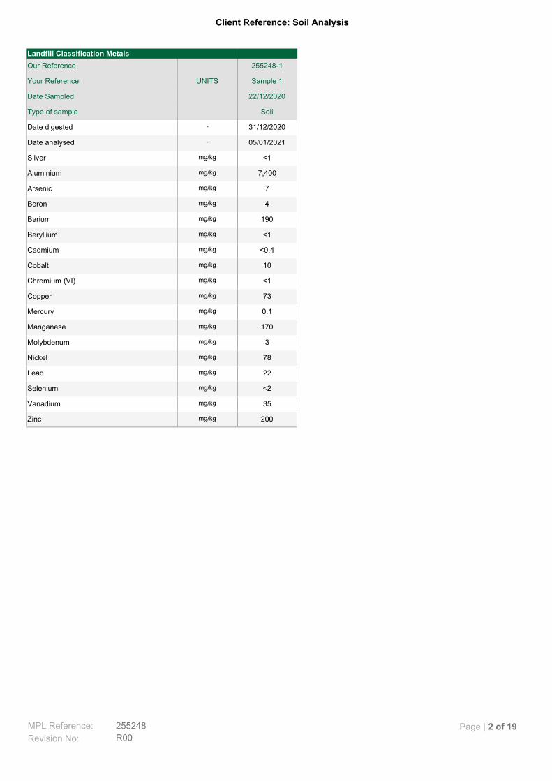
Client Reference: Soil Analysis
200mg/kgZinc
35mg/kgVanadium
<2mg/kgSelenium
22mg/kgLead
78mg/kgNickel
3mg/kgMolybdenum
170mg/kgManganese
0.1mg/kgMercury
73mg/kgCopper
<1mg/kgChromium (VI)
10mg/kgCobalt
<0.4mg/kgCadmium
<1mg/kgBeryllium
190mg/kgBarium
4mg/kgBoron
7mg/kgArsenic
7,400mg/kgAluminium
<1mg/kgSilver
05/01/2021-Date analysed
31/12/2020-Date digested
SoilType of sample
22/12/2020Date Sampled
Sample 1UNITSYour Reference
255248-1Our Reference
Landfill Classification Metals
MPL Reference: 255248
R00Revision No:
Page | 2 of 19

Client Reference: Soil Analysis
80%Surrogate aaa-Trifluorotoluene
<1mg/kgNaphthalene
<1mg/kgo-xylene
<2mg/kgm+p-xylene
<1mg/kgEthylbenzene
<0.5mg/kgToluene
<0.2mg/kgBenzene
<0.5mg/kgMTBE
170mg/kgTRH C6 -C10 less BTEX (F1)
170mg/kgTRH C6 - C10
32mg/kgTRH C6 - C9
04/01/2021-Date analysed
30/12/2020-Date extracted
SoilType of sample
22/12/2020Date Sampled
Sample 1UNITSYour Reference
255248-1Our Reference
vTRH(C6-C10)/MBTEXN in soil
MPL Reference: 255248
R00Revision No:
Page | 3 of 19

Client Reference: Soil Analysis
#%Surrogate 1-chlorooctadecane
1,900mg/kg>C16-C35 Aromatic
3,900mg/kg>C10-C16 Aromatic
230mg/kg>C35 Aliphatic
7,100mg/kg>C16-C35 Aliphatic
21,000mg/kg>C10-C16 Aliphatic
31/12/2020-Date analysed
30/12/2020-Date extracted
SoilType of sample
22/12/2020Date Sampled
Sample 1UNITSYour Reference
255248-1Our Reference
Aromatic & Aliphatic TPH
MPL Reference: 255248
R00Revision No:
Page | 4 of 19

Client Reference: Soil Analysis
#%Surrogate p-Terphenyl-D14
0.46mg/kgTotal Positive PAHs
<0.5mg/kgBenzo(a)pyrene TEQ calc(PQL)
<0.5mg/kgBenzo(a)pyrene TEQ calc(half)
<0.5mg/kgBenzo(a)pyrene TEQ calc (zero)
<0.1mg/kgBenzo(g,h,i)perylene
<0.1mg/kgDibenzo(a,h)anthracene
<0.1mg/kgIndeno(1,2,3-c,d)pyrene
<0.05mg/kgBenzo(a)pyrene
<0.2mg/kgBenzo(b,j+k)fluoranthene
<0.1mg/kgChrysene
<0.1mg/kgBenzo(a)anthracene
0.5mg/kgPyrene
<0.1mg/kgFluoranthene
<2mg/kgAnthracene
<2mg/kgPhenanthrene
<2mg/kgFluorene
<2mg/kgAcenaphthene
<0.1mg/kgAcenaphthylene
<2mg/kgNaphthalene
30/12/2020-Date analysed
30/12/2020-Date extracted
SoilType of sample
22/12/2020Date Sampled
Sample 1UNITSYour Reference
255248-1Our Reference
PAHs in Soil
MPL Reference: 255248
R00Revision No:
Page | 5 of 19
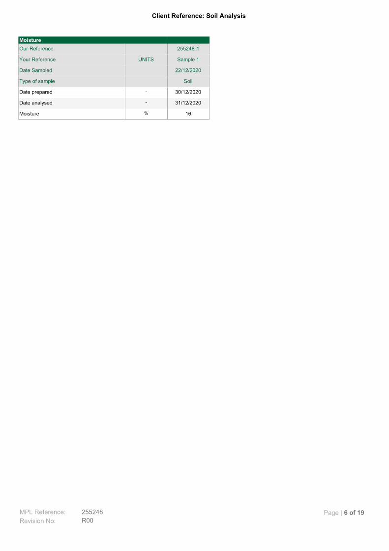
Client Reference: Soil Analysis
16%Moisture
31/12/2020-Date analysed
30/12/2020-Date prepared
SoilType of sample
22/12/2020Date Sampled
Sample 1UNITSYour Reference
255248-1Our Reference
Moisture
MPL Reference: 255248
R00Revision No:
Page | 6 of 19

Client Reference: Soil Analysis
<0.12mg/LSelenium in ASLP pH 5.0
<0.03mg/LLead in ASLP pH 5.0
0.06mg/LNickel in ASLP pH 5.0
<0.03mg/LMolybdenum in ASLP pH 5.0
<0.00005mg/LMercury in ASLP pH 5.0
0.01mg/LChromium in ASLP pH 5.0
<0.01mg/LCadmium in ASLP pH 5.0
<0.01mg/LBeryllium in ASLP pH 5.0
<0.01mg/LSilver in ASLP pH 5.0
0.09mg/LArsenic in ASLP pH 5.0
6.1pH unitspH of final Leachate
05/01/2021-Date analysed
04/01/2021-Date extracted
SoilType of sample
22/12/2020Date Sampled
Sample 1UNITSYour Reference
255248-1Our Reference
Metals in ASLP (pH 5.0)
MPL Reference: 255248
R00Revision No:
Page | 7 of 19

Client Reference: Soil Analysis
76%Surrogate p-Terphenyl-D14
<0.1µg/LBenzo(a)pyrene in ASLP pH5
6.5pH unitspH of final Leachate
31/12/2020-Date analysed
31/12/2020-Date extracted
SoilType of sample
22/12/2020Date Sampled
Sample 1UNITSYour Reference
255248-1Our Reference
PAHs in ASLP pH 5.0
MPL Reference: 255248
R00Revision No:
Page | 8 of 19

Client Reference: Soil Analysis
Soil samples are extracted with methanol and spiked into water prior to analysing by purge and trap GC-MS. Water samples are analysed directly by purge and trap GC-MS. F1 = (C6-C10)-BTEX as per NEPM B1 Guideline on Investigation Levels for Soil and Groundwater.
Org-023
Soil samples are extracted with Dichloromethane/Acetone and waters with Dichloromethane and analysed by GC-MS/GC-MSMS. Benzo(a)pyrene TEQ as per NEPM draft B1 Guideline on Investigation Levels for Soil and Groundwater.
Org-022/025
Soil samples are extracted with Dichloromethane/Acetone and waters with Dichloromethane and analysed by GC-MS/GC-MSMS.
Org-022/025
For soil results:- 1. ‘EQ PQL’values are assuming all contributing PAHs reported as <PQL are actually at the PQL. This is the most conservative approach and can give false positive TEQs given that PAHs that contribute to the TEQ calculation may not be present. 2. ‘EQ zero’values are assuming all contributing PAHs reported as <PQL are zero. This is the least conservative approach and is more susceptible to false negative TEQs when PAHs that contribute to the TEQ calculation are present but below PQL. 3. ‘EQ half PQL’values are assuming all contributing PAHs reported as <PQL are half the stipulated PQL. Hence a mid-point between the most and least conservative approaches above. Note, the Total +ve PAHs PQL is reflective of the lowest individual PQL and is therefore" Total +ve PAHs" is simply a sum of the positive individual PAHs.
Org-022/025
Soil samples are extracted with Dichloromethane/Acetone and waters with Dichloromethane and analysed by GC-FID. Fractionation with hexane through a silica gel column for aliphatics and DCM for aromatics.
Org-020
Determination of Mercury by Cold Vapour AAS. For urine samples total Mercury is determined, however, mercury in urine is almost entirely in the inorganic form (CDC).
METALS-021
Determination of various metals by ICP-AES.
METALS-020
Hexavalent Chromium by Ion Chromatographic separation and colourimetric determination.INORG-118
Moisture content determined by heating at 105 deg C for a minimum of 12 hours.
INORG-008
pH - Measured using pH meter and electrode in accordance with APHA latest edition, 4500-H+. Please note that the results for water analyses are indicative only, as analysis outside of the APHA storage times.
INORG-001
Methodology SummaryMethod ID
MPL Reference: 255248
R00Revision No:
Page | 9 of 19

Client Reference: Soil Analysis
[NT]122[NT]2001<1METALS-0201mg/kgZinc
[NT]119[NT]351<1METALS-0201mg/kgVanadium
[NT]110[NT]<21<2METALS-0202mg/kgSelenium
[NT]125[NT]221<1METALS-0201mg/kgLead
[NT]121[NT]781<1METALS-0201mg/kgNickel
[NT]115[NT]31<1METALS-0201mg/kgMolybdenum
[NT]121[NT]1701<1METALS-0201mg/kgManganese
[NT]1120<0.10.11<0.1METALS-0210.1mg/kgMercury
[NT]125[NT]731<1METALS-0201mg/kgCopper
[NT]1050<1<11<1INORG-1181mg/kgChromium (VI)
[NT]118[NT]101<1METALS-0201mg/kgCobalt
[NT]113[NT]<0.41<0.4METALS-0200.4mg/kgCadmium
[NT]113[NT]<11<1METALS-0201mg/kgBeryllium
[NT]123[NT]1901<1METALS-0201mg/kgBarium
[NT]116[NT]41<3METALS-0203mg/kgBoron
[NT]112[NT]71<2METALS-0202mg/kgArsenic
[NT]107[NT]74001<10METALS-02010mg/kgAluminium
[NT]123[NT]<11<1METALS-0201mg/kgSilver
[NT]05/01/202105/01/202105/01/2021105/01/2021-Date analysed
[NT]31/12/202031/12/202031/12/2020131/12/2020-Date digested
[NT]LCS-1RPDDup.Base#BlankMethodPQLUnitsTest Description
Spike Recovery %DuplicateQUALITY CONTROL: Landfill Classification Metals
MPL Reference: 255248
R00Revision No:
Page | 10 of 19

Client Reference: Soil Analysis
[NT]8148380183Org-023%Surrogate aaa-Trifluorotoluene
[NT][NT]0<1<11<1Org-0231mg/kgNaphthalene
[NT]750<1<11<1Org-0231mg/kgo-xylene
[NT]740<2<21<2Org-0232mg/kgm+p-xylene
[NT]740<1<11<1Org-0231mg/kgEthylbenzene
[NT]760<0.5<0.51<0.5Org-0230.5mg/kgToluene
[NT]830<0.2<0.21<0.2Org-0230.2mg/kgBenzene
[NT][NT]0<0.5<0.51<0.5Org-0230.5mg/kgMTBE
[NT]76191401701<25Org-02325mg/kgTRH C6 - C10
[NT]76333321<25Org-02325mg/kgTRH C6 - C9
[NT]04/01/202104/01/202104/01/2021104/01/2021-Date analysed
[NT]30/12/202030/12/202030/12/2020130/12/2020-Date extracted
[NT]LCS-1RPDDup.Base#BlankMethodPQLUnitsTest Description
Spike Recovery %DuplicateQUALITY CONTROL: vTRH(C6-C10)/MBTEXN in soil
MPL Reference: 255248
R00Revision No:
Page | 11 of 19

Client Reference: Soil Analysis
[NT]81##170Org-020%Surrogate 1-chlorooctadecane
[NT]11424150019001<50Org-02050mg/kg>C16-C35 Aromatic
[NT]11444250039001<50Org-02050mg/kg>C10-C16 Aromatic
[NT]105202802301<100Org-020100mg/kg>C35 Aliphatic
[NT]10914820071001<100Org-020100mg/kg>C16-C35 Aliphatic
[NT]1171324000210001<100Org-020100mg/kg>C10-C16 Aliphatic
[NT]31/12/202031/12/202031/12/2020131/12/2020-Date analysed
[NT]30/12/202030/12/202030/12/2020130/12/2020-Date extracted
[NT]LCS-1RPDDup.Base#BlankMethodPQLUnitsTest Description
Spike Recovery %DuplicateQUALITY CONTROL: Aromatic & Aliphatic TPH
MPL Reference: 255248
R00Revision No:
Page | 12 of 19
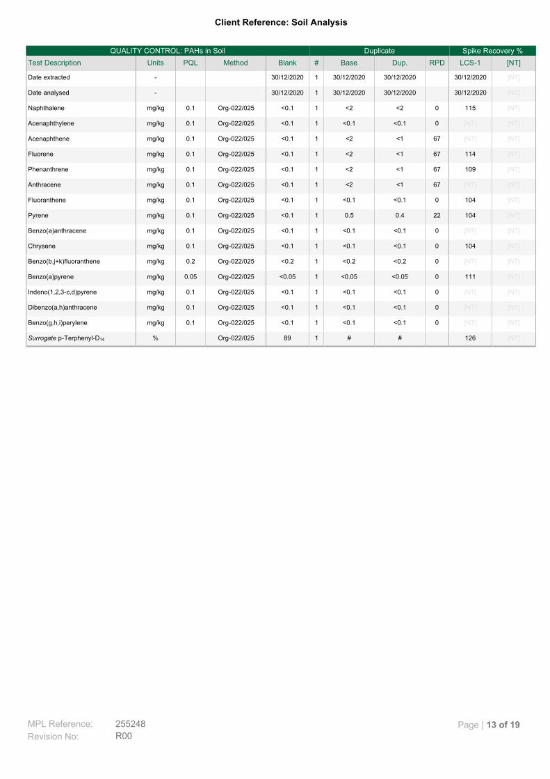
Client Reference: Soil Analysis
[NT]126##189Org-022/025%Surrogate p-Terphenyl-D14
[NT][NT]0<0.1<0.11<0.1Org-022/0250.1mg/kgBenzo(g,h,i)perylene
[NT][NT]0<0.1<0.11<0.1Org-022/0250.1mg/kgDibenzo(a,h)anthracene
[NT][NT]0<0.1<0.11<0.1Org-022/0250.1mg/kgIndeno(1,2,3-c,d)pyrene
[NT]1110<0.05<0.051<0.05Org-022/0250.05mg/kgBenzo(a)pyrene
[NT][NT]0<0.2<0.21<0.2Org-022/0250.2mg/kgBenzo(b,j+k)fluoranthene
[NT]1040<0.1<0.11<0.1Org-022/0250.1mg/kgChrysene
[NT][NT]0<0.1<0.11<0.1Org-022/0250.1mg/kgBenzo(a)anthracene
[NT]104220.40.51<0.1Org-022/0250.1mg/kgPyrene
[NT]1040<0.1<0.11<0.1Org-022/0250.1mg/kgFluoranthene
[NT][NT]67<1<21<0.1Org-022/0250.1mg/kgAnthracene
[NT]10967<1<21<0.1Org-022/0250.1mg/kgPhenanthrene
[NT]11467<1<21<0.1Org-022/0250.1mg/kgFluorene
[NT][NT]67<1<21<0.1Org-022/0250.1mg/kgAcenaphthene
[NT][NT]0<0.1<0.11<0.1Org-022/0250.1mg/kgAcenaphthylene
[NT]1150<2<21<0.1Org-022/0250.1mg/kgNaphthalene
[NT]30/12/202030/12/202030/12/2020130/12/2020-Date analysed
[NT]30/12/202030/12/202030/12/2020130/12/2020-Date extracted
[NT]LCS-1RPDDup.Base#BlankMethodPQLUnitsTest Description
Spike Recovery %DuplicateQUALITY CONTROL: PAHs in Soil
MPL Reference: 255248
R00Revision No:
Page | 13 of 19
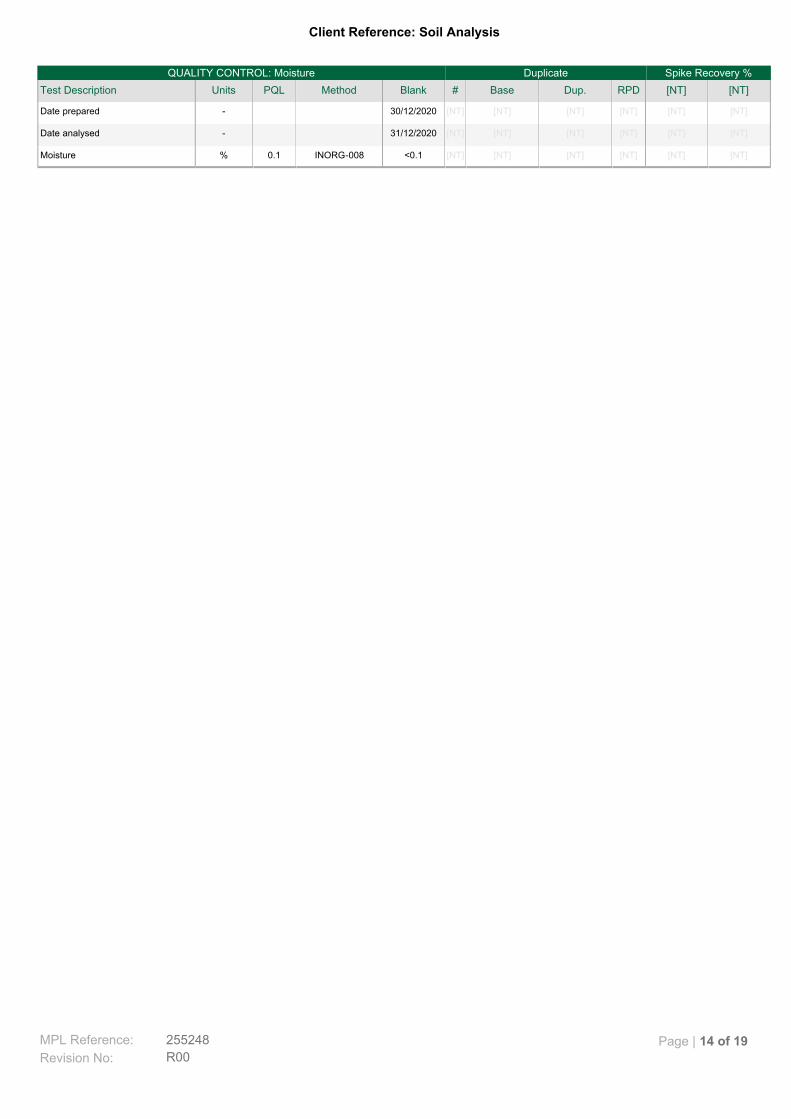
Client Reference: Soil Analysis
[NT][NT][NT][NT][NT][NT]<0.1INORG-0080.1%Moisture
[NT][NT][NT][NT][NT][NT]31/12/2020-Date analysed
[NT][NT][NT][NT][NT][NT]30/12/2020-Date prepared
[NT][NT]RPDDup.Base#BlankMethodPQLUnitsTest Description
Spike Recovery %DuplicateQUALITY CONTROL: Moisture
MPL Reference: 255248
R00Revision No:
Page | 14 of 19

Client Reference: Soil Analysis
[NT]1010<0.12<0.121<0.12METALS-0200.12mg/LSelenium in ASLP pH 5.0
[NT]1030<0.03<0.031<0.03METALS-0200.03mg/LLead in ASLP pH 5.0
[NT]10000.060.061<0.02METALS-0200.02mg/LNickel in ASLP pH 5.0
[NT]1060<0.03<0.031<0.03METALS-0200.03mg/LMolybdenum in ASLP pH 5.0
[NT]1000<0.00005<0.000051<0.00005METALS-0210.00005mg/LMercury in ASLP pH 5.0
[NT]1050<0.010.011<0.01METALS-0200.01mg/LChromium in ASLP pH 5.0
[NT]980<0.01<0.011<0.01METALS-0200.01mg/LCadmium in ASLP pH 5.0
[NT]1000<0.01<0.011<0.01METALS-0200.01mg/LBeryllium in ASLP pH 5.0
[NT]880<0.01<0.011<0.01METALS-0200.01mg/LSilver in ASLP pH 5.0
[NT]105250.070.091<0.05METALS-0200.05mg/LArsenic in ASLP pH 5.0
[NT]05/01/202105/01/202105/01/2021105/01/2021-Date analysed
[NT]04/01/202104/01/202104/01/2021104/01/2021-Date extracted
[NT]LCS-1RPDDup.Base#BlankMethodPQLUnitsTest Description
Spike Recovery %DuplicateQUALITY CONTROL: Metals in ASLP (pH 5.0)
MPL Reference: 255248
R00Revision No:
Page | 15 of 19
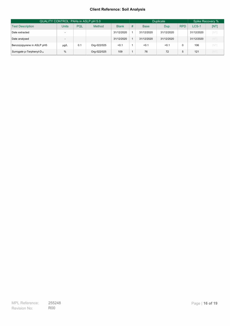
Client Reference: Soil Analysis
[NT]121572761109Org-022/025%Surrogate p-Terphenyl-D14
[NT]1060<0.1<0.11<0.1Org-022/0250.1µg/LBenzo(a)pyrene in ASLP pH5
[NT]31/12/202031/12/202031/12/2020131/12/2020-Date analysed
[NT]31/12/202031/12/202031/12/2020131/12/2020-Date extracted
[NT]LCS-1RPDDup.Base#BlankMethodPQLUnitsTest Description
Spike Recovery %DuplicateQUALITY CONTROL: PAHs in ASLP pH 5.0
MPL Reference: 255248
R00Revision No:
Page | 16 of 19

Client Reference: Soil Analysis
Not ReportedNR
National Environmental Protection MeasureNEPM
Not specifiedNS
Laboratory Control SampleLCS
Relative Percent DifferenceRPD
Greater than>
Less than<
Practical Quantitation LimitPQL
Insufficient sample for this testINS
Test not requiredNA
Not testedNT
Result Definitions
MPL Reference: 255248
R00Revision No:
Page | 17 of 19

Client Reference: Soil Analysis
Guideline limits for Rinse Water Quality reported as per analytical requirements and specifications of AS 4187, Amdt 2 2019, Table7.2
The recommended maximums for analytes in urine are taken from “2018 TLVs and BEIs”, as published by ACGIH (where available).Limit provided for Nickel is a precautionary guideline as per Position Paper prepared by AIOH Exposure Standards Committee,2016.
Australian Drinking Water Guidelines recommend that Thermotolerant Coliform, Faecal Enterococci, & E.Coli levels are less than1cfu/100mL. The recommended maximums are taken from "Australian Drinking Water Guidelines", published by NHMRC & ARMC2011.
Surrogates are known additions to each sample, blank, matrix spike and LCS in a batch, of compounds whichare similar to the analyte of interest, however are not expected to be found in real samples.
Surrogate Spike
This comprises either a standard reference material or a control matrix (such as a blank sand or water) fortifiedwith analytes representative of the analyte class. It is simply a check sample.
LCS (LaboratoryControl Sample)
A portion of the sample is spiked with a known concentration of target analyte. The purpose of the matrix spikeis to monitor the performance of the analytical method used and to determine whether matrix interferencesexist.
Matrix Spike
This is the complete duplicate analysis of a sample from the process batch. If possible, the sample selectedshould be one where the analyte concentration is easily measurable.
Duplicate
This is the component of the analytical signal which is not derived from the sample but from reagents,glassware etc, can be determined by processing solvents and reagents in exactly the same manner as forsamples.
Blank
Quality Control Definitions
Samples for Microbiological analysis (not Amoeba forms) received outside of the 2-8°C temperature range do not meet the idealcooling conditions as stated in AS2031-2012.
Measurement Uncertainty estimates are available for most tests upon request.
Where sampling dates are not provided, Envirolab are not in a position to comment on the validity of the analysis whererecommended technical holding times may have been breached.
When samples are received where certain analytes are outside of recommended technical holding times (THTs), the analysis hasproceeded. Where analytes are on the verge of breaching THTs, every effort will be made to analyse within the THT or as soon aspracticable.
In circumstances where no duplicate and/or sample spike has been reported at 1 in 10 and/or 1 in 20 samples respectively, thesample volume submitted was insufficient in order to satisfy laboratory QA/QC protocols.
Matrix Spikes, LCS and Surrogate recoveries: Generally 70-130% for inorganics/metals (not SPOCAS); 60-140% fororganics/SPOCAS (+/-50% surrogates) and 10-140% for labile SVOCs (including labile surrogates), ultra trace organics andspeciated phenols is acceptable.
Duplicates: >10xPQL - RPD acceptance criteria will vary depending on the analytes and the analytical techniques but is typically inthe range 20%-50% – see ELN-P05 QA/QC tables for details; <10xPQL - RPD are higher as the results approach PQL and theestimated measurement uncertainty will statistically increase.
For VOCs in water samples, three vials are required for duplicate or spike analysis.
Spikes for Physical and Aggregate Tests are not applicable.
Filters, swabs, wipes, tubes and badges will not have duplicate data as the whole sample is generally extracted during sampleextraction.
Duplicate sample and matrix spike recoveries may not be reported on smaller jobs, however, were analysed at a frequency to meetor exceed NEPM requirements. All samples are tested in batches of 20. The duplicate sample RPD and matrix spike recoveries forthe batch were within the laboratory acceptance criteria.
Laboratory Acceptance Criteria
MPL Reference: 255248
R00Revision No:
Page | 18 of 19
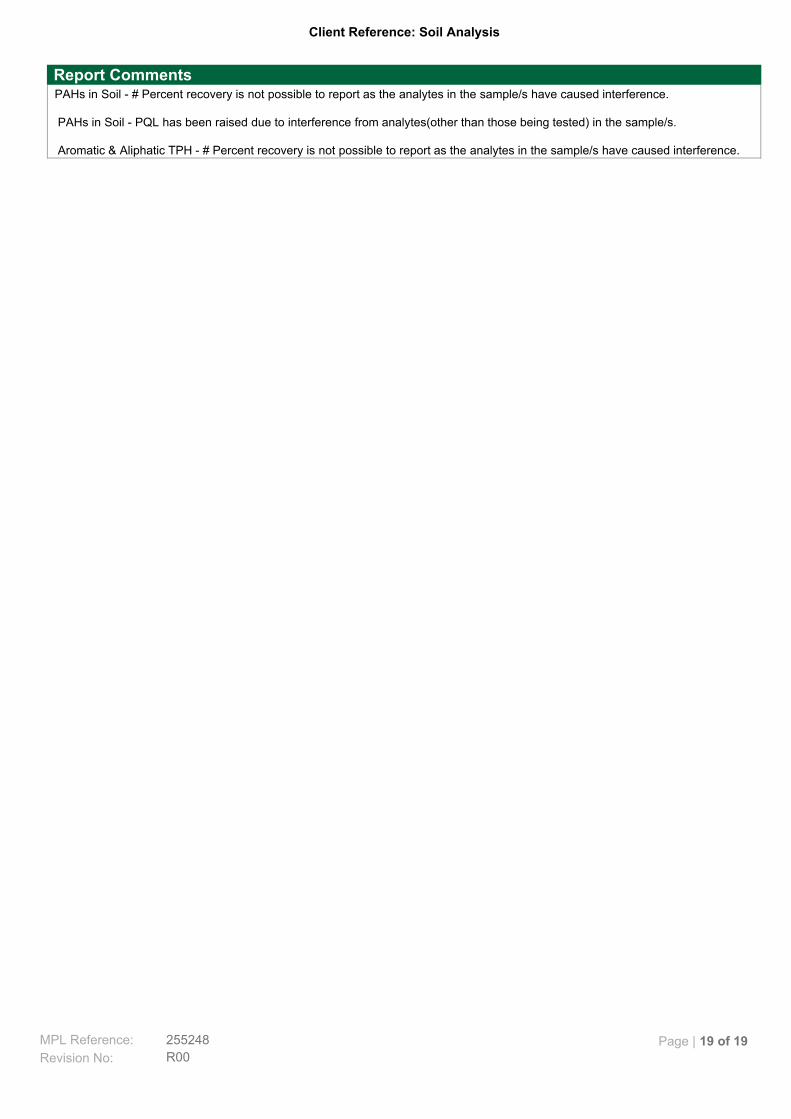
Client Reference: Soil Analysis
PAHs in Soil - # Percent recovery is not possible to report as the analytes in the sample/s have caused interference. PAHs in Soil - PQL has been raised due to interference from analytes(other than those being tested) in the sample/s. Aromatic & Aliphatic TPH - # Percent recovery is not possible to report as the analytes in the sample/s have caused interference.
Report Comments
MPL Reference: 255248
R00Revision No:
Page | 19 of 19