Embed Size (px)
Citation preview
Application of inertial sensors in rehabilitation robotics
E. Rocon, J.C. Moreno, A.F. Ruiz, F. Brunetti, J.A. Miranda, J.L. Pons
Abstract— MicroElectroMechanical Systems (MEMS) arerevolutionizing a multitude of industries world wide, fromconsumer products to the scientific community. Rehabilitationrobotics is a robotic field specially interested in using theadvantages of inertial sensors. The essential aspect in this areais the intrinsic interaction between human and robot, whichimposes several restrictions in the design of this sort of robots.This paper addresses the analysis of the application of inertialsensors as sensing technologies in controlled orthotic deviceswith a detailed analysis with two biomechatronic roboticsrehabilitation exoskeletons, one for the upper and other forthe lower limb. Eventually, the results and conclusion of theexperiments are given.
Index Terms— inertial sensing, orthotics, rehabilitationrobotics, MEMS.
I. I NTRODUCTION
MicroElectroMechanical Systems (MEMS) are revolution-izing a multitude of industries world wide, from consumerproducts to the scientific community. Motion sensing, bymeans of MEMS inertial sensors, could be applied to a widearray of consumer products - laptops computers, cell phones,PDAs, camcoders, digital cameras, gaming, computer inputdevices and pagers. Another enormous field which is us-ing inertial sensors are the automotive application. Safety,passenger comfort, vehicle performance and navigation aretriggering new and tremendorous demand for inertial sensors.
In addition, these sensors represented a real scientificbreakthrough in the medical field, where there is a need forsmall ambulatory sensor systems for measuring the kinemat-ics of body segments. Inertial sensors would enable ambu-latory biomechanical measurements. Since micromachinedsensors such as gyroscopes and accelerometers have becomegenerally available, human movement can be measured con-tinuously outside a specialized laboratory with ambulatorysystems.
Lately, the application of this technology in robotics fieldis increasing very fast, mainly in robot navigation whichrequires six-degrees-of-freedom motion estimation, both ac-celeration and angular rate about three axes. The greater theability to sense the full motion of the robot and its parts, thebetter the control over its behavior. This technology is beingused together with others sensors applied in robot navigation,for instance cameras, since each can be used to resolvethe ambiguities in estimated motion that result from usingthe other modality alone. For instance, image measurements
Corresponding author: [email protected]. Rocon, J.C. Moreno, A.F. Ruiz, F. Brunetti and J.L. Pons, are
with the Biomedical Engineering Group at Consejo Superior de Inves-tigaciones Cientıficas, Ctra. Campo Real, km. 0,200, 28500 Argandadel Rey, Madrid, Spain. J.A. Miranda is with Technaid S.L., [email protected]
can counteract the error that accumulates when integratinginertial readings, and can be used to distinguish betweenthe effects of sensor orientation, acceleration, gravity, andbias in accelerometer measurements. On the other hand,inertial data can resolve the ambiguities in motion estimatedby a camera that sees a degenerate scene, such as onecontaining too few features, features infinitely far away, orfeatures in an accidental geometric configuration; to removethe discontinuities in estimated motion that can result fromfeatures entering or leaving the camera’s field of view; toestablish the global scale; and to make motion estimationmore robust to mistracked image features [1].
Another area of robotics which is specially interested inusing the advantages of inertial sensors is the rehabilitationrobotics field. The scientific community is becoming moreand more interested in the so-called Rehabilitation Robotics.Rehabilitation robots are robots intended to restore or replacesome human function. Over the last decade, the introduc-tion of robotic technologies into rehabilitation settings hasprogressed from concept to reality. Numerous studies havedemonstrated the efficacy and advantages of rehabilitationrobots for assessing and treating motor impairments in boththe upper and lower extremities [2]–[5].
The essential aspect in this area is the intrinsic interactionbetween human and robot. This interaction has a twofoldscenario: first, a cognitive interaction that allows the humanto control the robot while it feeds information back to thehuman; second, a biomechanical interaction leading to theapplication of controlled forces between both actors. Bothfactors influence the different components of the system suchas the sensors of the robot.
In this sort of application, there is a need to obtainvariables such as joint angular accelerations and angularvelocities to close control loops chasing specific goals.In addition, the sensor should have specific characteristicssuch as low size with long battery life, should be able toextract a wide range of parameters from human motion,easy adaptability to an orthotic frame, proper bandwidth andother preferred features. These characteristic made MEMSinertial sensors very attractive for rehabilitation roboticsfield. Despite the increase number of applications employinginertial sensor, rehabilitation robots are still not exploring allthe benefits of this technology.
Rehabilitation robotics applications requires the analy-sis of the body motion in order to close control loopsaround defined joints. Nowadays, there are many systemsfor measuring body segment position and angles betweensegments. Commercial optical systems such as Vicon, [6], areconsidered the standard in human motion analysis. Although
1-4244-1320-6/07/$25.00 (c)2007 IEEE 145
Proceedings of the 2007 IEEE 10th International Conference on Rehabilitation Robotics, June 12-15, Noordwijk, The Netherlands
this system provides accurate position information, there aresome significant limitations such as high costs and limitedmeasure volume. They have to be used in laboratories witha fixed equipment, which impedes its use in rehabilitationrobotics applications, like exoskeletons. This has promotedthe use of inertial sensors in rehabilitation robotics field.
Inertial sensors give an output signal proportional to itsown motion respect to an inertial frame of reference, allow-ing the fabrication of motion sensors ”internally referenced”.The vestibular system, located in the inner ear, is a biological3D inertial sensor. It can sense angular motion as well aslinear acceleration of the head. Micromachining techniquesmake possible the development of precision inertial sensorswith a lower price and standard characteristics similar tothose of integrated circuits, suitable for portable and wearableapplications.
Miniature sensor units are placed on each body segmentto be analyzed. A rate gyroscope measures angular velocityrelying on the Coriolis force principle during angular rate bymeasuring capacitance. An accelerometer measures accelera-tion governed by a physical principal known as Hookes law.Noise and bias errors associate with small sensors make itunpractical to track orientation and position changes for longtime periods if no compensation is applied [7].
Combinations of three axial gyroscopes and accelerom-eters, have been proposed to obtain complete kinematicsof single sensor units, [8], [9]. Application in robotic nav-igation systems has been broadly investigated, combinedwith other wide scale positioning techniques (i.e., GPS).But applications in robotics concerning measurement andcontrol of human motion commonly require a method toobtain segments orientation. Integration of angular velocitygiven by a gyroscope can be used as a method to esti-mate orientation, if compensation methods to correct theresultant integration drift are used, which is mainly causedby fluctuation of the sensor offset. Such compensation infree motion applications, can be performed using inclinationdata from three axial accelerometers, together with a prioriknowledge of a particular movement, such as constraintsimposed by joints, as described by Luinge, [10], for theupper arm. Also, when rhythmic movements are involved(i.e., walking, tremor), cyclical compensatory mechanismscan be applied to accurately obtain orientations or to obtainquantities of interest to fed a given controller of motion, aswill be presented in this paper.
Despite the massive use of inertial sensors a a tool toanalyze motion in robotic applications, few are used forclosing control loops. The robotics devices presented inthis paper successfully use their sensors in order to closespecific control loops. This paper addresses the analysis ofinertial sensors as sensing technologies in controlled orthoticdevices. It aims at illustrating the successful use of thisparticular technology in two rehabilitation robots recentlydeveloped. In both applications, in addition to measurehuman motion, these sensors were successfully used forclosing specific control loops, without affecting the stabilityof the devices. The analysis will be complemented by the
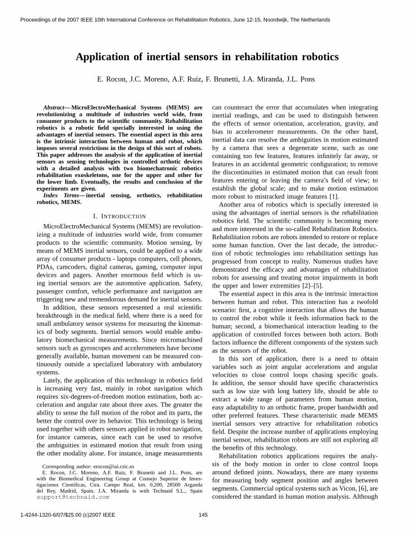
Fig. 1. WOTAS exoskeleton for tremor suppression.
description of experimental results of inertial sensors thatdemonstrates its application on wearable robotic systems. Inthe next section, the main principles for movement analysisbased on inertial sensors are described. In section III and IV,experiments with two biomechatronic robotics rehabilitationexoskeletons for the upper and lower limb will be shown.Eventually, some discussion on the conclusions and futurework are given.
II. ON THE USE OFRATE GYROSCOPES FORTREMOR
SENSING IN THE HUMAN UPPERL IMB
WOTAS (Wearable Orthosis for Tremor Assessment andSuppression) is an active upper limb exoskeleton based onrobotics technologies capable of applying forces to can-cel tremor and retrieve kinematic information from thetremorous upper limb, [4]. WOTAS follows the kinematicsstructure of the human upper limb and spans the elbow andwrist joints. It exhibits three degrees of freedom correspond-ing to elbow flexo-extension, forearm pronation-supinationand wrist flexo extension, see figure 1. In order to monitorand suppress tremor, the WOTAS exoskeleton is equippedwith kinematic (angular position, velocity and acceleration)and kinetic (interaction force between limb and exoskeleton)sensors. Tremor force, position, velocity and acceleration arethe required information to implement control strategies.
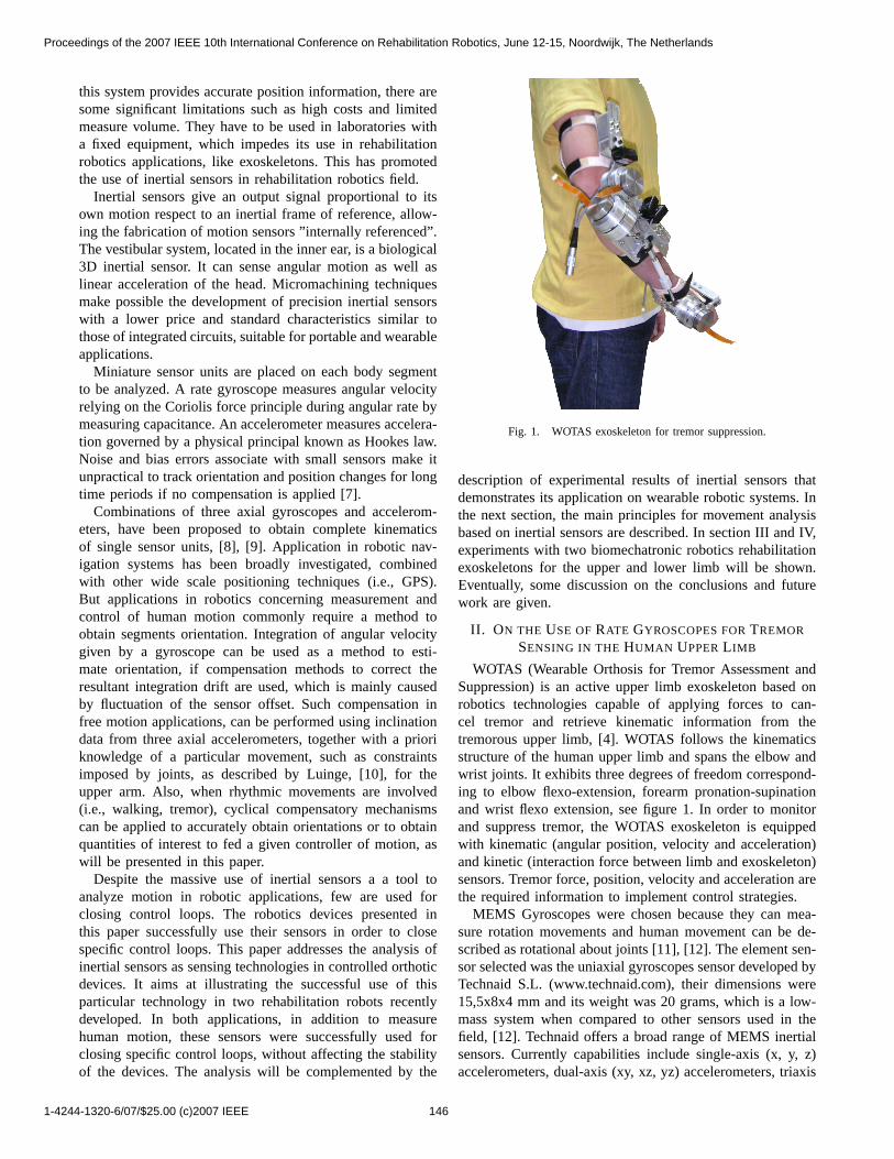
MEMS Gyroscopes were chosen because they can mea-sure rotation movements and human movement can be de-scribed as rotational about joints [11], [12]. The element sen-sor selected was the uniaxial gyroscopes sensor developed byTechnaid S.L. (www.technaid.com), their dimensions were15,5x8x4 mm and its weight was 20 grams, which is a low-mass system when compared to other sensors used in thefield, [12]. Technaid offers a broad range of MEMS inertialsensors. Currently capabilities include single-axis (x, y, z)accelerometers, dual-axis (xy, xz, yz) accelerometers, triaxis
1-4244-1320-6/07/$25.00 (c)2007 IEEE 146
Proceedings of the 2007 IEEE 10th International Conference on Rehabilitation Robotics, June 12-15, Noordwijk, The Netherlands
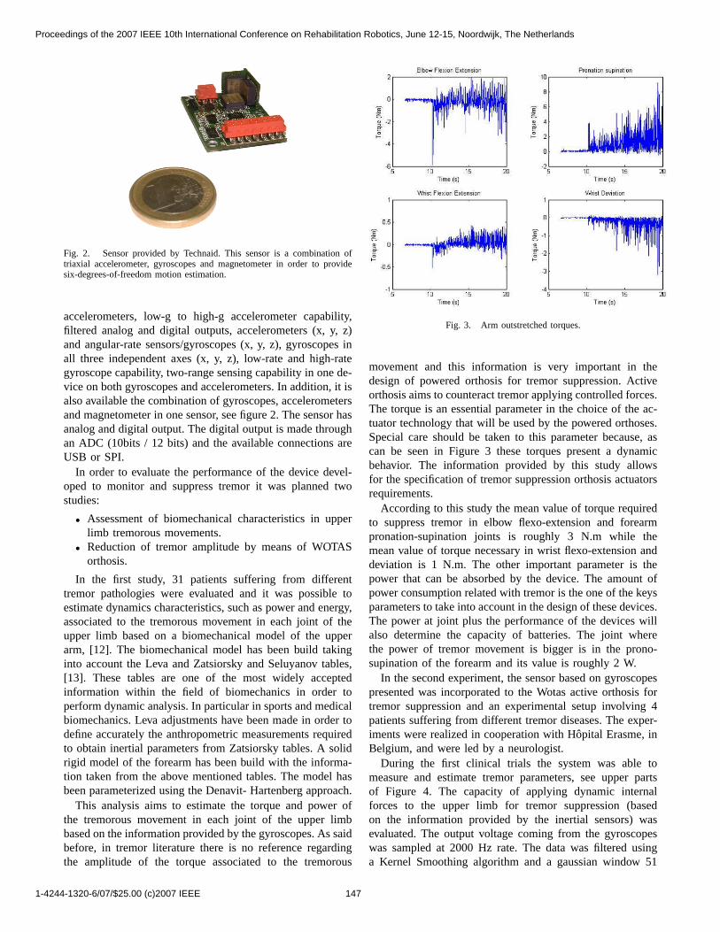
Fig. 2. Sensor provided by Technaid. This sensor is a combination oftriaxial accelerometer, gyroscopes and magnetometer in order to providesix-degrees-of-freedom motion estimation.
accelerometers, low-g to high-g accelerometer capability,filtered analog and digital outputs, accelerometers (x, y, z)and angular-rate sensors/gyroscopes (x, y, z), gyroscopes inall three independent axes (x, y, z), low-rate and high-rategyroscope capability, two-range sensing capability in one de-vice on both gyroscopes and accelerometers. In addition, it isalso available the combination of gyroscopes, accelerometersand magnetometer in one sensor, see figure 2. The sensor hasanalog and digital output. The digital output is made throughan ADC (10bits / 12 bits) and the available connections areUSB or SPI.
In order to evaluate the performance of the device devel-oped to monitor and suppress tremor it was planned twostudies:
• Assessment of biomechanical characteristics in upperlimb tremorous movements.
• Reduction of tremor amplitude by means of WOTASorthosis.
In the first study, 31 patients suffering from differenttremor pathologies were evaluated and it was possible toestimate dynamics characteristics, such as power and energy,associated to the tremorous movement in each joint of theupper limb based on a biomechanical model of the upperarm, [12]. The biomechanical model has been build takinginto account the Leva and Zatsiorsky and Seluyanov tables,[13]. These tables are one of the most widely acceptedinformation within the field of biomechanics in order toperform dynamic analysis. In particular in sports and medicalbiomechanics. Leva adjustments have been made in order todefine accurately the anthropometric measurements requiredto obtain inertial parameters from Zatsiorsky tables. A solidrigid model of the forearm has been build with the informa-tion taken from the above mentioned tables. The model hasbeen parameterized using the Denavit- Hartenberg approach.
This analysis aims to estimate the torque and power ofthe tremorous movement in each joint of the upper limbbased on the information provided by the gyroscopes. As saidbefore, in tremor literature there is no reference regardingthe amplitude of the torque associated to the tremorous
Fig. 3. Arm outstretched torques.
movement and this information is very important in thedesign of powered orthosis for tremor suppression. Activeorthosis aims to counteract tremor applying controlled forces.The torque is an essential parameter in the choice of the ac-tuator technology that will be used by the powered orthoses.Special care should be taken to this parameter because, ascan be seen in Figure 3 these torques present a dynamicbehavior. The information provided by this study allowsfor the specification of tremor suppression orthosis actuatorsrequirements.
According to this study the mean value of torque requiredto suppress tremor in elbow flexo-extension and forearmpronation-supination joints is roughly 3 N.m while themean value of torque necessary in wrist flexo-extension anddeviation is 1 N.m. The other important parameter is thepower that can be absorbed by the device. The amount ofpower consumption related with tremor is the one of the keysparameters to take into account in the design of these devices.The power at joint plus the performance of the devices willalso determine the capacity of batteries. The joint wherethe power of tremor movement is bigger is in the prono-supination of the forearm and its value is roughly 2 W.
In the second experiment, the sensor based on gyroscopespresented was incorporated to the Wotas active orthosis fortremor suppression and an experimental setup involving 4patients suffering from different tremor diseases. The exper-iments were realized in cooperation with Hopital Erasme, inBelgium, and were led by a neurologist.
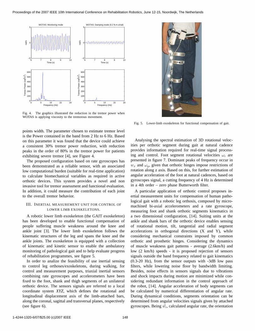
During the first clinical trials the system was able tomeasure and estimate tremor parameters, see upper partsof Figure 4. The capacity of applying dynamic internalforces to the upper limb for tremor suppression (basedon the information provided by the inertial sensors) wasevaluated. The output voltage coming from the gyroscopeswas sampled at 2000 Hz rate. The data was filtered usinga Kernel Smoothing algorithm and a gaussian window 51
1-4244-1320-6/07/$25.00 (c)2007 IEEE 147
Proceedings of the 2007 IEEE 10th International Conference on Rehabilitation Robotics, June 12-15, Noordwijk, The Netherlands
6 7 8 9 10−5
0
5WOTAS: Monitoring mode
Time (s)
rad/
s
6 7 8 9 10−5
0
5WOTAS: Damping mode (0.2 N.m.s/rad)
Time (s)
rad/
s
0 5 10 15 200
100
200
300
400
500
600
Frequency (Hz)
Tre
mor
Pow
er (
rad2 /s
3 )
0 5 10 15 200
100
200
300
400
500
600
Frequency (Hz)
Tre
mor
Pow
er (
rad2 /s
3 )
Fig. 4. The graphics illustrated the reduction in the tremor power whenWOTAS is applying viscosity to the tremorous movement.
points width. The parameter chosen to estimate tremor levelis the Power contained in the band from 2 Hz to 6 Hz. Basedon this parameter it was found that the device could achievea consistent 30% tremor power reduction, with reductionpeaks in the order of 80% in the tremor power for patientsexhibiting severe tremor [4], see Figure 4.
The proposed configuration based on rate gyroscopes hasbeen demonstrated as a reliable sensor, with an associatedlow computational burden (suitable for real-time application)to calculate biomechanical variables as required in activeorthotic devices. This system provides a novel and noninvasive tool for tremor assessment and functional evaluation.In addition, it could measure the contribution of each jointto the overall tremor behavior.
III. I NERTIAL MEASUREMENT UNIT FOR CONTROL OF
LOWER LIMB EXOSKELETONS.
A robotic lower limb exoskeleton (the GAIT exoskeleton)has been developed to enable functional compensation ofpeople suffering muscle weakness around the knee andankle joint [3]. The lower limb exoskeleton follows thekinematic structures of the leg and spans the knee and theankle joints. The exoskeleton is equipped with a collectionof kinematic and kinetic sensor to enable the ambulatorymonitoring of pathological gait and to help evaluate progressof rehabilitation programmes, see figure 5.
In order to analize the feasibility of use inertial sensingto control leg orthoses/exoskeletons, during walking, forcontrol and measurement purposes, triaxial inertial sensorscombining rate gyroscopes and accelerometers have beenfixed to the foot, shank and thigh segments of an unilateralorthotic device. The sensors signals are referred to a localcoordinate systemXYZ, which defines the rotational andlongitudinal displacement axis of the limb-attached bars,along the coronal, sagittal and transversal planes, respectively(see figure 6).
Fig. 5. Lower-limb exoskeleton for functional compensation of gait.
Analysing the spectral estimation of 3D rotational veloc-ities per orthotic segment during gait at natural cadenceprovides information required for real-time signal process-ing and control. Foot segment rotational velocitiesωi arepresented in figure 7. Dominant peaks of frequency occur inwx andωy, given that orthotic hinges impose restrictions ofrotation along z axis. Based on this, for further estimation ofangular acceleration of the foot at natural cadences, based ongyroscopes signal, a cutting frequency of 4 Hz is determinedin a 4th order – zero phase Butterworth filter.
A particular application of orthotic control proposes in-ertial measurement units for compensation of human patho-logical gait with a robotic leg orthosis, composed by micro-machined bi-axial accelerometers and a rate gyroscope,measuring foot and shank orthotic segments kinematics ina two dimensional configuration, [14]. Suiting units at theankle and shank bars of the orthotic device enables sensingof rotational motion, tilt, tangential and radial segmentaccelerations in orthogonal directions (X and Y), whileconsidering mechanical constraints imposed by commonorthotic and prosthetic hinges. Considering the dynamicsof muscle weakness gait patterns - average (2.6km/h) andlow (2 km/h) speeds - it is proposed rejection of sensorssignals outside the band frequency related to gait kinematics(0.3-20 Hz), from the sensor outputs with -3dB low passfilters, while lowering noise floor by bandwidth limiting.Besides, noise effects in sensors signals due to vibrationsand shock impacts during motion are minimized while con-sidering redundant information in the control approach ofthe robot, [14]. Angular acceleration of body segments canbe calculated by numerical differentiation of angular rate.During dynamical conditions, segments orientation can bedetermined from angular velocities signals given by attachedgyroscopes. Being~wi, calculated angular rate, the orientation
1-4244-1320-6/07/$25.00 (c)2007 IEEE 148
Proceedings of the 2007 IEEE 10th International Conference on Rehabilitation Robotics, June 12-15, Noordwijk, The Netherlands
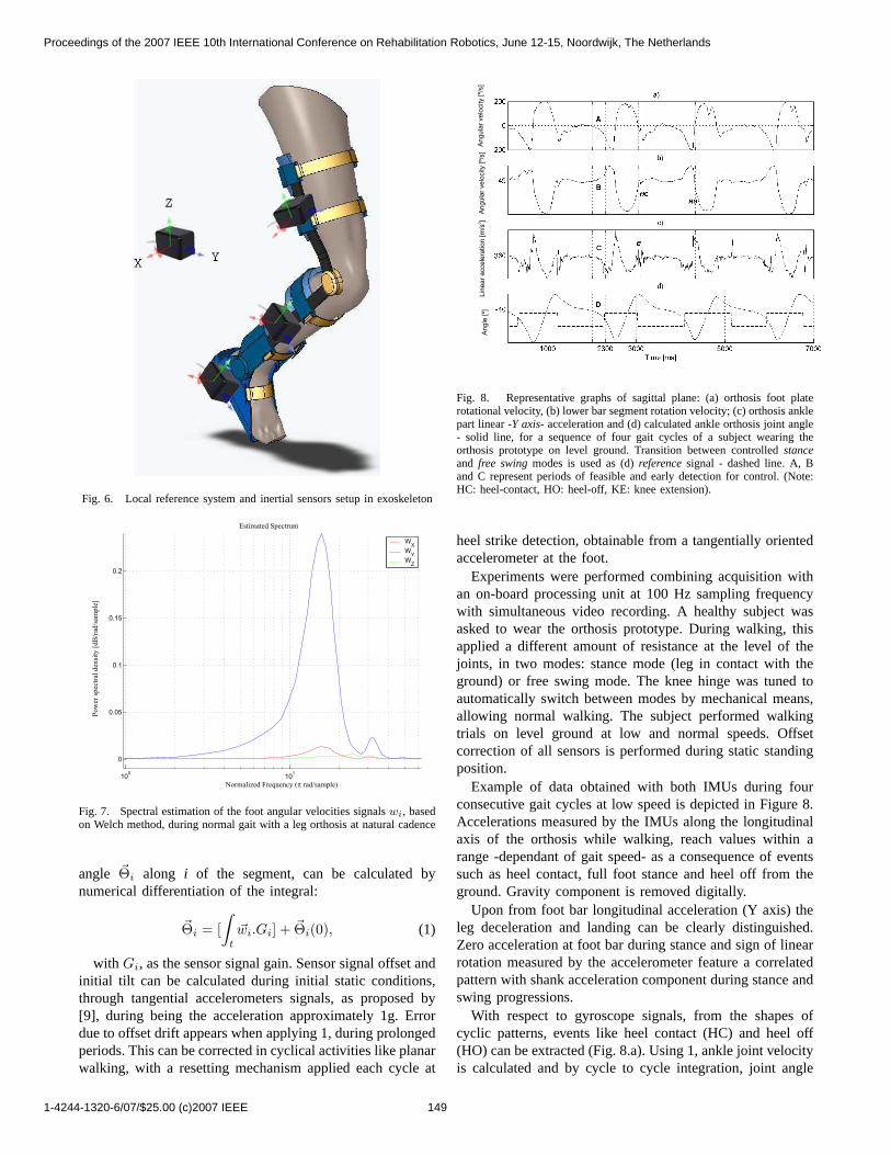
Fig. 6. Local reference system and inertial sensors setup in exoskeleton
Estimated Spectrum
Normalized Frequency ( rad/sample)p
Pow
er s
pec
tral
den
sity
[dB
/rad
/sam
ple
]
Fig. 7. Spectral estimation of the foot angular velocities signalswi, basedon Welch method, during normal gait with a leg orthosis at natural cadence
angle ~Θi along i of the segment, can be calculated bynumerical differentiation of the integral:
~Θi = [∫
t
~wi.Gi] + ~Θi(0), (1)
with Gi, as the sensor signal gain. Sensor signal offset andinitial tilt can be calculated during initial static conditions,through tangential accelerometers signals, as proposed by[9], during being the acceleration approximately 1g. Errordue to offset drift appears when applying 1, during prolongedperiods. This can be corrected in cyclical activities like planarwalking, with a resetting mechanism applied each cycle at
An
gu
lar
ve
locity [
º/s]
An
gu
lar
ve
locity [
º/s]
Lin
ea
r a
cce
lera
tio
n [
m/s
]2
An
gle
[º]
Fig. 8. Representative graphs of sagittal plane: (a) orthosis foot platerotational velocity, (b) lower bar segment rotation velocity; (c) orthosis anklepart linear -Y axis- acceleration and (d) calculated ankle orthosis joint angle- solid line, for a sequence of four gait cycles of a subject wearing theorthosis prototype on level ground. Transition between controlledstanceand free swingmodes is used as (d)referencesignal - dashed line. A, Band C represent periods of feasible and early detection for control. (Note:HC: heel-contact, HO: heel-off, KE: knee extension).
heel strike detection, obtainable from a tangentially orientedaccelerometer at the foot.
Experiments were performed combining acquisition withan on-board processing unit at 100 Hz sampling frequencywith simultaneous video recording. A healthy subject wasasked to wear the orthosis prototype. During walking, thisapplied a different amount of resistance at the level of thejoints, in two modes: stance mode (leg in contact with theground) or free swing mode. The knee hinge was tuned toautomatically switch between modes by mechanical means,allowing normal walking. The subject performed walkingtrials on level ground at low and normal speeds. Offsetcorrection of all sensors is performed during static standingposition.
Example of data obtained with both IMUs during fourconsecutive gait cycles at low speed is depicted in Figure 8.Accelerations measured by the IMUs along the longitudinalaxis of the orthosis while walking, reach values within arange -dependant of gait speed- as a consequence of eventssuch as heel contact, full foot stance and heel off from theground. Gravity component is removed digitally.
Upon from foot bar longitudinal acceleration (Y axis) theleg deceleration and landing can be clearly distinguished.Zero acceleration at foot bar during stance and sign of linearrotation measured by the accelerometer feature a correlatedpattern with shank acceleration component during stance andswing progressions.
With respect to gyroscope signals, from the shapes ofcyclic patterns, events like heel contact (HC) and heel off(HO) can be extracted (Fig. 8.a). Using 1, ankle joint velocityis calculated and by cycle to cycle integration, joint angle
1-4244-1320-6/07/$25.00 (c)2007 IEEE 149
Proceedings of the 2007 IEEE 10th International Conference on Rehabilitation Robotics, June 12-15, Noordwijk, The Netherlands
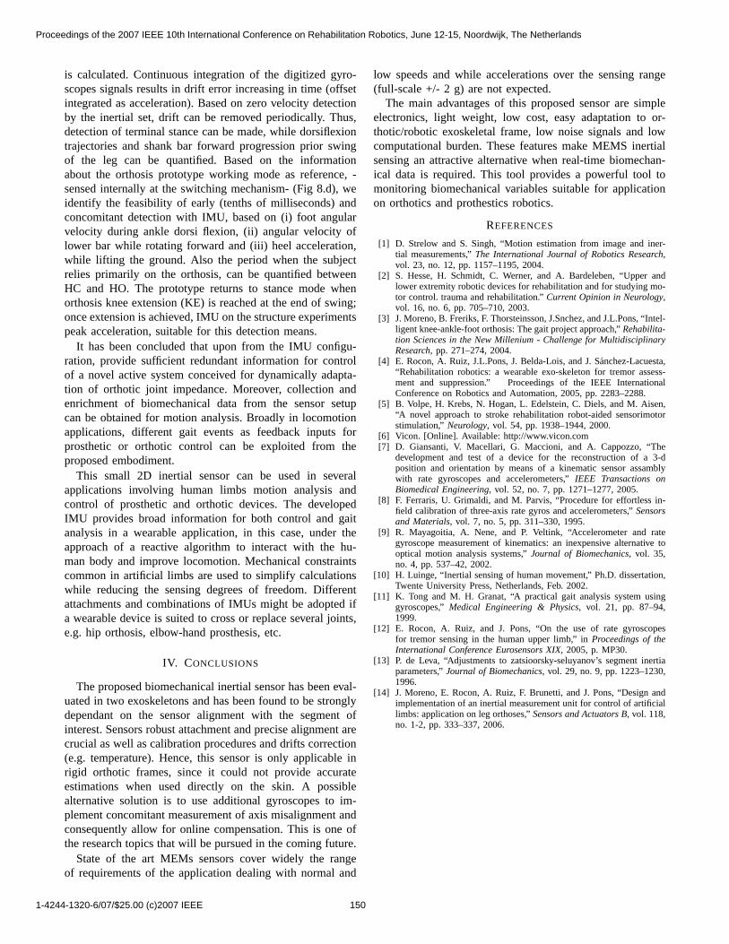
is calculated. Continuous integration of the digitized gyro-scopes signals results in drift error increasing in time (offsetintegrated as acceleration). Based on zero velocity detectionby the inertial set, drift can be removed periodically. Thus,detection of terminal stance can be made, while dorsiflexiontrajectories and shank bar forward progression prior swingof the leg can be quantified. Based on the informationabout the orthosis prototype working mode as reference, -sensed internally at the switching mechanism- (Fig 8.d), weidentify the feasibility of early (tenths of milliseconds) andconcomitant detection with IMU, based on (i) foot angularvelocity during ankle dorsi flexion, (ii) angular velocity oflower bar while rotating forward and (iii) heel acceleration,while lifting the ground. Also the period when the subjectrelies primarily on the orthosis, can be quantified betweenHC and HO. The prototype returns to stance mode whenorthosis knee extension (KE) is reached at the end of swing;once extension is achieved, IMU on the structure experimentspeak acceleration, suitable for this detection means.
It has been concluded that upon from the IMU configu-ration, provide sufficient redundant information for controlof a novel active system conceived for dynamically adapta-tion of orthotic joint impedance. Moreover, collection andenrichment of biomechanical data from the sensor setupcan be obtained for motion analysis. Broadly in locomotionapplications, different gait events as feedback inputs forprosthetic or orthotic control can be exploited from theproposed embodiment.
This small 2D inertial sensor can be used in severalapplications involving human limbs motion analysis andcontrol of prosthetic and orthotic devices. The developedIMU provides broad information for both control and gaitanalysis in a wearable application, in this case, under theapproach of a reactive algorithm to interact with the hu-man body and improve locomotion. Mechanical constraintscommon in artificial limbs are used to simplify calculationswhile reducing the sensing degrees of freedom. Differentattachments and combinations of IMUs might be adopted ifa wearable device is suited to cross or replace several joints,e.g. hip orthosis, elbow-hand prosthesis, etc.
IV. CONCLUSIONS
The proposed biomechanical inertial sensor has been eval-uated in two exoskeletons and has been found to be stronglydependant on the sensor alignment with the segment ofinterest. Sensors robust attachment and precise alignment arecrucial as well as calibration procedures and drifts correction(e.g. temperature). Hence, this sensor is only applicable inrigid orthotic frames, since it could not provide accurateestimations when used directly on the skin. A possiblealternative solution is to use additional gyroscopes to im-plement concomitant measurement of axis misalignment andconsequently allow for online compensation. This is one ofthe research topics that will be pursued in the coming future.
State of the art MEMs sensors cover widely the rangeof requirements of the application dealing with normal and
low speeds and while accelerations over the sensing range(full-scale +/- 2 g) are not expected.
The main advantages of this proposed sensor are simpleelectronics, light weight, low cost, easy adaptation to or-thotic/robotic exoskeletal frame, low noise signals and lowcomputational burden. These features make MEMS inertialsensing an attractive alternative when real-time biomechan-ical data is required. This tool provides a powerful tool tomonitoring biomechanical variables suitable for applicationon orthotics and prothestics robotics.
REFERENCES
[1] D. Strelow and S. Singh, “Motion estimation from image and iner-tial measurements,”The International Journal of Robotics Research,vol. 23, no. 12, pp. 1157–1195, 2004.
[2] S. Hesse, H. Schmidt, C. Werner, and A. Bardeleben, “Upper andlower extremity robotic devices for rehabilitation and for studying mo-tor control. trauma and rehabilitation.”Current Opinion in Neurology,vol. 16, no. 6, pp. 705–710, 2003.
[3] J. Moreno, B. Freriks, F. Thorsteinsson, J.Snchez, and J.L.Pons, “Intel-ligent knee-ankle-foot orthosis: The gait project approach,”Rehabilita-tion Sciences in the New Millenium - Challenge for MultidisciplinaryResearch, pp. 271–274, 2004.
[4] E. Rocon, A. Ruiz, J.L.Pons, J. Belda-Lois, and J. Sanchez-Lacuesta,“Rehabilitation robotics: a wearable exo-skeleton for tremor assess-ment and suppression.” Proceedings of the IEEE InternationalConference on Robotics and Automation, 2005, pp. 2283–2288.
[5] B. Volpe, H. Krebs, N. Hogan, L. Edelstein, C. Diels, and M. Aisen,“A novel approach to stroke rehabilitation robot-aided sensorimotorstimulation,” Neurology, vol. 54, pp. 1938–1944, 2000.
[6] Vicon. [Online]. Available: http://www.vicon.com[7] D. Giansanti, V. Macellari, G. Maccioni, and A. Cappozzo, “The
development and test of a device for the reconstruction of a 3-dposition and orientation by means of a kinematic sensor assamblywith rate gyroscopes and accelerometers,”IEEE Transactions onBiomedical Engineering, vol. 52, no. 7, pp. 1271–1277, 2005.
[8] F. Ferraris, U. Grimaldi, and M. Parvis, “Procedure for effortless in-field calibration of three-axis rate gyros and accelerometers,”Sensorsand Materials, vol. 7, no. 5, pp. 311–330, 1995.
[9] R. Mayagoitia, A. Nene, and P. Veltink, “Accelerometer and rategyroscope measurement of kinematics: an inexpensive alternative tooptical motion analysis systems,”Journal of Biomechanics, vol. 35,no. 4, pp. 537–42, 2002.
[10] H. Luinge, “Inertial sensing of human movement,” Ph.D. dissertation,Twente University Press, Netherlands, Feb. 2002.
[11] K. Tong and M. H. Granat, “A practical gait analysis system usinggyroscopes,”Medical Engineering & Physics, vol. 21, pp. 87–94,1999.
[12] E. Rocon, A. Ruiz, and J. Pons, “On the use of rate gyroscopesfor tremor sensing in the human upper limb,” inProceedings of theInternational Conference Eurosensors XIX, 2005, p. MP30.
[13] P. de Leva, “Adjustments to zatsioorsky-seluyanov’s segment inertiaparameters,”Journal of Biomechanics, vol. 29, no. 9, pp. 1223–1230,1996.
[14] J. Moreno, E. Rocon, A. Ruiz, F. Brunetti, and J. Pons, “Design andimplementation of an inertial measurement unit for control of artificiallimbs: application on leg orthoses,”Sensors and Actuators B, vol. 118,no. 1-2, pp. 333–337, 2006.
1-4244-1320-6/07/$25.00 (c)2007 IEEE 150
Proceedings of the 2007 IEEE 10th International Conference on Rehabilitation Robotics, June 12-15, Noordwijk, The Netherlands