Embed Size (px)
Citation preview
APT3700N Smart Pressure Transmitter for Nuclear Service Operation Manual M3700N-K01E
1
AUTROLⓇ Series
Operation Manual : M3700N-K01E
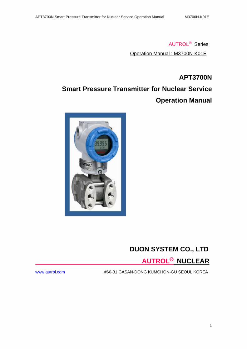
APT3700N
Smart Pressure Transmitter for Nuclear Service
Operation Manual
DUON SYSTEM CO., LTD
AUTROLⓇ NUCLEAR
www.autrol.com #60-31 GASAN-DONG KUMCHON-GU SEOUL KOREA
APT3700N Smart Pressure Transmitter for Nuclear Service Operation Manual M3700N-K01E
2
Notice-2
User's manual DOC. NO. M3700N-K01x
“Smart Pressure Transmitter for Nuclear service Operational Manual”
REV. Submission Date Description
K01A '03.04.10 First Made
K01B '05.07.18 4-8 Revised
K01C '09.05.27 3-7 Revised
K01D '10.08.26 Article 1-2 Revised &
6-5 added
K01E '10.10.15 Front Revised

APT3700N Smart Pressure Transmitter for Nuclear Service Operation Manual M3700N-K01E
3
The following Manual may change without the user's notice.
APT3700N Smart Pressure Transmitter for Nuclear Service Operation Manual M3700N-K01E
4
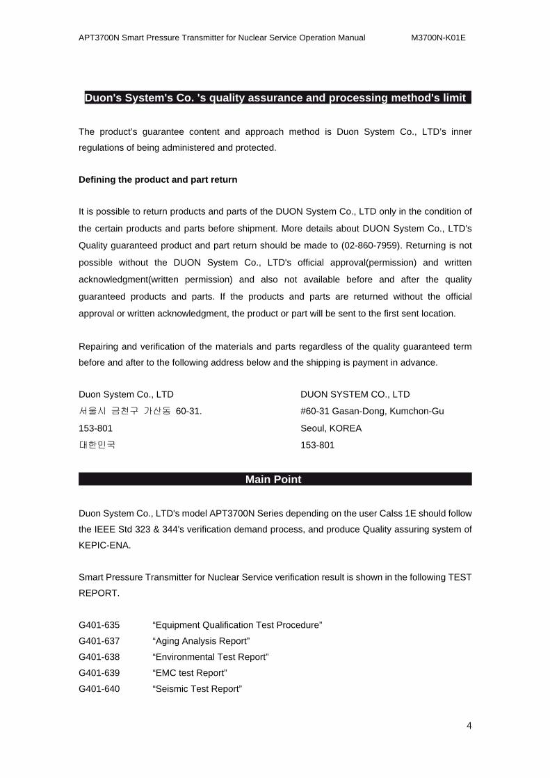
Duon's System's Co. 's quality assurance and processing method's limit
The product’s guarantee content and approach method is Duon System Co., LTD’s inner
regulations of being administered and protected.
Defining the product and part return
It is possible to return products and parts of the DUON System Co., LTD only in the condition of
the certain products and parts before shipment. More details about DUON System Co., LTD's
Quality guaranteed product and part return should be made to (02-860-7959). Returning is not
possible without the DUON System Co., LTD's official approval(permission) and written
acknowledgment(written permission) and also not available before and after the quality
guaranteed products and parts. If the products and parts are returned without the official
approval or written acknowledgment, the product or part will be sent to the first sent location.
Repairing and verification of the materials and parts regardless of the quality guaranteed term
before and after to the following address below and the shipping is payment in advance.
Duon System Co., LTD DUON SYSTEM CO., LTD
서울시 금천구 가산동 60-31. #60-31 Gasan-Dong, Kumchon-Gu
153-801 Seoul, KOREA
대한민국 153-801
Main Point
Duon System Co., LTD's model APT3700N Series depending on the user Calss 1E should follow
the IEEE Std 323 & 344's verification demand process, and produce Quality assuring system of
KEPIC-ENA.
Smart Pressure Transmitter for Nuclear Service verification result is shown in the following TEST
REPORT.
G401-635 “Equipment Qualification Test Procedure”
G401-637 “Aging Analysis Report”
G401-638 “Environmental Test Report”
G401-639 “EMC test Report”
G401-640 “Seismic Test Report”

APT3700N Smart Pressure Transmitter for Nuclear Service Operation Manual M3700N-K01E
5
Notes
APT3700N Smart Pressure Transmitter for Nuclear Service Operation Manual M3700N-K01E
6
Table of Contents
1. Introduction ...............................................................................................................8
1.1. Overview … ………………………………………………………………….……..8
1.2. Smart Pressure Transmitter ………………………………………………………8
2. Installation …………………………………………………………………………………11
2.1. Overview …………………………………………………………………………….11
2.2. General Consideration ……………………………………………………………..11
2.3. Mechanical Consideration ………………………………………………………….11
2.3.1. Process Connection …………………………………………………………12
2.3.2. Conduit ……………………………………………………………………….13
2.4. Electric Consideration ………………………………………………………………14
2.4.1. Power Supply and Load Resistance ………………………………………17
2.5. Install Consideration ………………………………………………………………..18
2.5.1. Mechanical …………………………………………………………………...18
2.5.2. Electronic ……………………………………………………………………..18
3. Calibration ………………………………………………………………………………….21
3.1. Overview ……………………………………………………………………………..21
3.2. ZERO …………………………………………………………………………………21
3.3. ZERO Adjustment …………………………………………………………………..22
3.4. ZERO Trim …………………………………………………………………………..23
3.5. SPAN …………………………………………………………………………………23
3.6. Damping Adjustment ……………………………………………………………….24
3.7. Button Function ……………………………………………………………………..25
4. OPERATION ………………………………………………………………………………31
4.1. Overview …………………………………………………………………………….31
4.2. Transmitter Operation & Sensor ………………………………………………….32
4.3. Transmitter's Max Electricity ………………………………………………………33
4.4. Safety of Inserting in Reverse Direction ………………………………………….33
4.5. Installation Place ……………………………………………………………………34
4.6. Conditions after Installation ………………………………………………………..34
4.7. Connecting to Pressure …………………………………………………………….34
4.8. Wireless Transmitter's Limitations ………………………………………………...35
APT3700N Smart Pressure Transmitter for Nuclear Service Operation Manual M3700N-K01E
7
5. Maintenance and Troubleshooting ………………………………………………………36
5.1. Overview ……………………………………………………………………………..36
5.2. Safety Message ……………………………………………………………………..36
5.3. Test Terminal ………………………………………………………………………..37
5.4. Board …………………………………………………………………………………37
5.5. Maintenance …………………………………………………………………………38
5.5.1. Test Terminal ………………………………………………………………...38
5.5.2. Quick Manual ………………………………………………………………..40
5.6. Troubleshooting ……………………………………………………………………..41
5.7. Spare Part ……………………………………………………………………………43
5.8. Spare Parts storage, storing way and period ……………………………………43
5.9. LCD Code ……………………………………………………………………………44
6. Specification and Reference Data ………………………………………………………46
6.1. Overview …………………………………………………………………………….46
6.2. Nuclear Specification ………………………………………………………………46
6.3. Environment Condition & SEISMIC Condition …………………………………..46
6.4. Quality Assurance Program ……………………………………………………….46
6.4.1. Nuclear Cleaning ……………………………………………………………46
6.4.2. Hydrostatic and Pneumatic Pressure Testing ……………………………46
6.4.3. Traceability …………………………………………………………………..47
6.4.4. Qualified Life …………………………………………………………………47
6.5. Performance Specification …………………………………………………………47
6.6. Functional Specification ……………………………………………………………48
6.7. Physical Specification ………………………………………………………………49
6.8. Ordering Information ………………………………………………………………..51
APT3700N Smart Pressure Transmitter for Nuclear Service Operation Manual M3700N-K01E
8
1.1. Introduction DUON SYSTEM CO., LTD
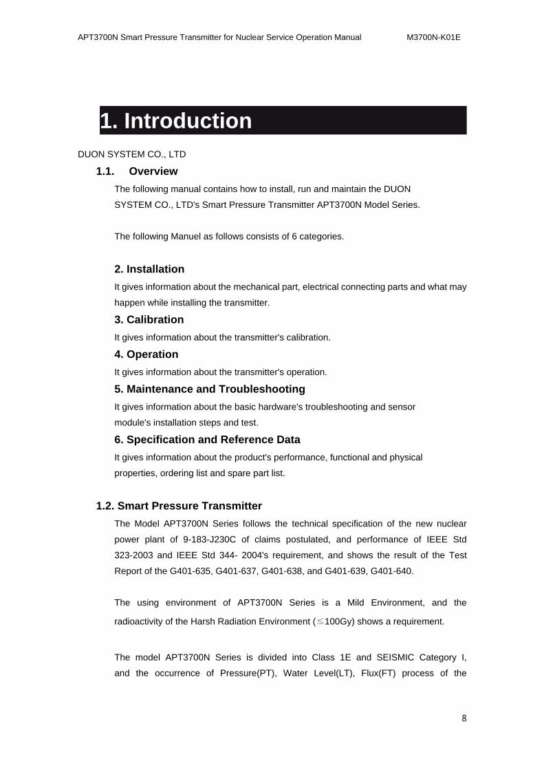
1.1. Overview
The following manual contains how to install, run and maintain the DUON
SYSTEM CO., LTD's Smart Pressure Transmitter APT3700N Model Series.
The following Manuel as follows consists of 6 categories.
2. Installation
It gives information about the mechanical part, electrical connecting parts and what may
happen while installing the transmitter.
3. Calibration
It gives information about the transmitter's calibration.
4. Operation
It gives information about the transmitter's operation.
5. Maintenance and Troubleshooting
It gives information about the basic hardware's troubleshooting and sensor
module's installation steps and test.
6. Specification and Reference Data
It gives information about the product's performance, functional and physical
properties, ordering list and spare part list.
1.2. Smart Pressure Transmitter
The Model APT3700N Series follows the technical specification of the new nuclear
power plant of 9-183-J230C of claims postulated, and performance of IEEE Std
323-2003 and IEEE Std 344- 2004's requirement, and shows the result of the Test
Report of the G401-635, G401-637, G401-638, and G401-639, G401-640.
The using environment of APT3700N Series is a Mild Environment, and the
radioactivity of the Harsh Radiation Environment (≤100Gy) shows a requirement.
The model APT3700N Series is divided into Class 1E and SEISMIC Category I,
and the occurrence of Pressure(PT), Water Level(LT), Flux(FT) process of the

APT3700N Smart Pressure Transmitter for Nuclear Service Operation Manual M3700N-K01E
9
nuclear energy of the power plant of the high rank system shows a function of the
4~20mA signal of the Digital communication HART Protocol transmitter.

APT3700N Smart Pressure Transmitter for Nuclear Service Operation Manual M3700N-K01E
10
Notes
APT3700N Smart Pressure Transmitter for Nuclear Service Operation Manual M3700N-K01E
11
2.2. Installation
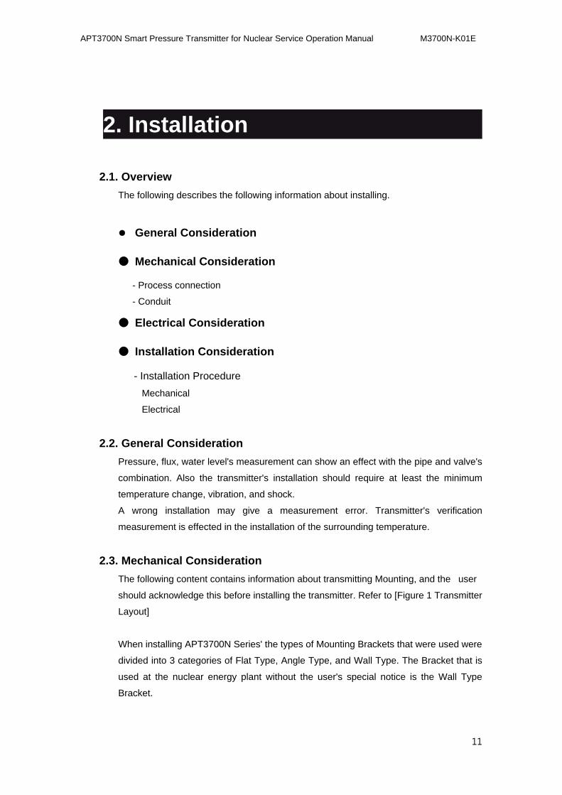
2.1. Overview
The following describes the following information about installing.
● General Consideration
● Mechanical Consideration
- Process connection
- Conduit
● Electrical Consideration
● Installation Consideration
- Installation Procedure
Mechanical
Electrical
2.2. General Consideration
Pressure, flux, water level's measurement can show an effect with the pipe and valve's
combination. Also the transmitter's installation should require at least the minimum
temperature change, vibration, and shock.
A wrong installation may give a measurement error. Transmitter's verification
measurement is effected in the installation of the surrounding temperature.
2.3. Mechanical Consideration
The following content contains information about transmitting Mounting, and the user
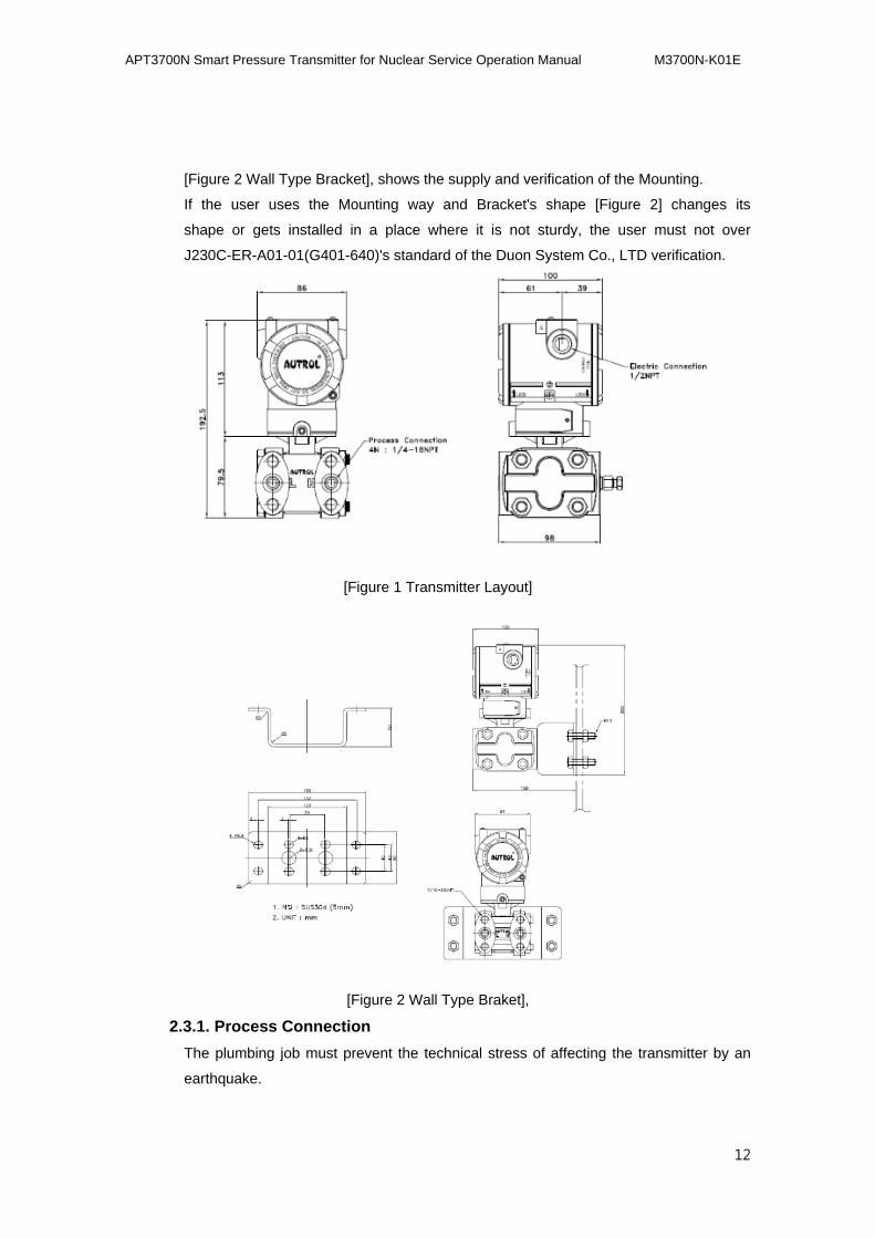
should acknowledge this before installing the transmitter. Refer to [Figure 1 Transmitter
Layout]
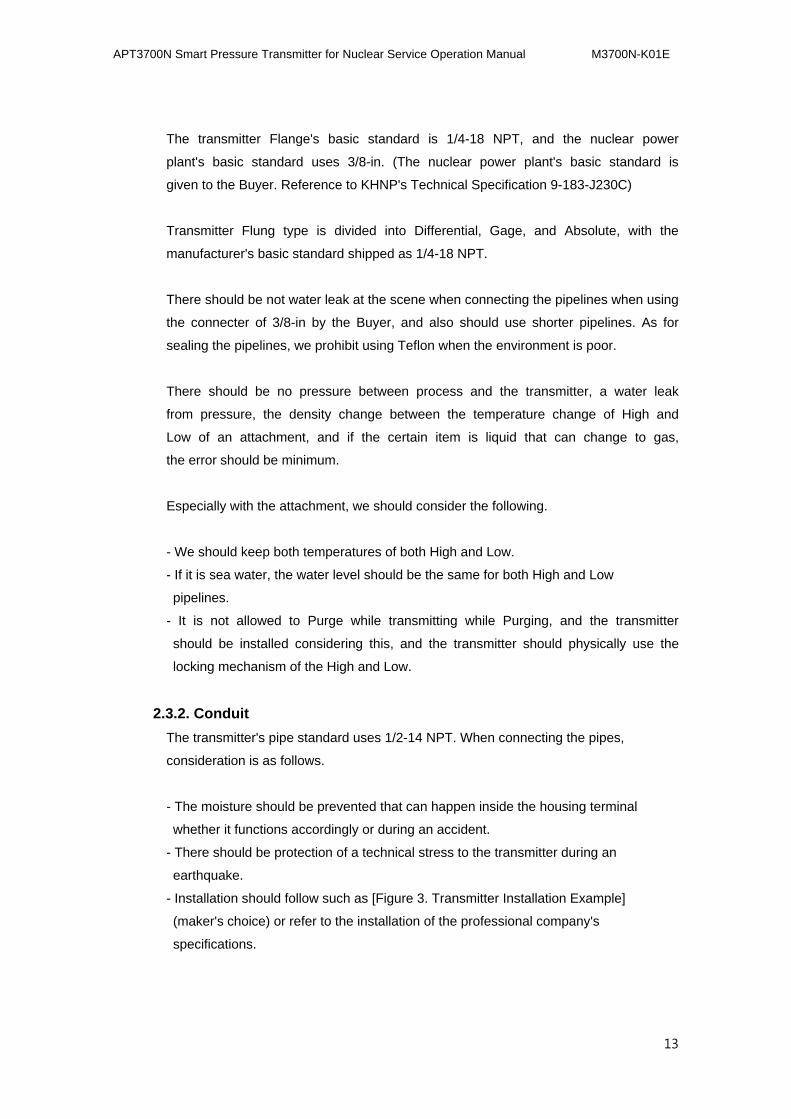
When installing APT3700N Series' the types of Mounting Brackets that were used were
divided into 3 categories of Flat Type, Angle Type, and Wall Type. The Bracket that is
used at the nuclear energy plant without the user's special notice is the Wall Type
Bracket.
APT3700N Smart Pressure Transmitter for Nuclear Service Operation Manual M3700N-K01E
12
[Figure 2 Wall Type Bracket], shows the supply and verification of the Mounting.
If the user uses the Mounting way and Bracket's shape [Figure 2] changes its
shape or gets installed in a place where it is not sturdy, the user must not over
J230C-ER-A01-01(G401-640)'s standard of the Duon System Co., LTD verification.
[Figure 1 Transmitter Layout]
[Figure 2 Wall Type Braket],
2.3.1. Process Connection
The plumbing job must prevent the technical stress of affecting the transmitter by an
earthquake.
APT3700N Smart Pressure Transmitter for Nuclear Service Operation Manual M3700N-K01E
13
The transmitter Flange's basic standard is 1/4-18 NPT, and the nuclear power
plant's basic standard uses 3/8-in. (The nuclear power plant's basic standard is
given to the Buyer. Reference to KHNP's Technical Specification 9-183-J230C)
Transmitter Flung type is divided into Differential, Gage, and Absolute, with the
manufacturer's basic standard shipped as 1/4-18 NPT.
There should be not water leak at the scene when connecting the pipelines when using
the connecter of 3/8-in by the Buyer, and also should use shorter pipelines. As for
sealing the pipelines, we prohibit using Teflon when the environment is poor.
There should be no pressure between process and the transmitter, a water leak
from pressure, the density change between the temperature change of High and
Low of an attachment, and if the certain item is liquid that can change to gas,
the error should be minimum.
Especially with the attachment, we should consider the following.
- We should keep both temperatures of both High and Low.
- If it is sea water, the water level should be the same for both High and Low
pipelines.
- It is not allowed to Purge while transmitting while Purging, and the transmitter
should be installed considering this, and the transmitter should physically use the
locking mechanism of the High and Low.
2.3.2. Conduit
The transmitter's pipe standard uses 1/2-14 NPT. When connecting the pipes,
consideration is as follows.
- The moisture should be prevented that can happen inside the housing terminal
whether it functions accordingly or during an accident.
- There should be protection of a technical stress to the transmitter during an
earthquake.
- Installation should follow such as [Figure 3. Transmitter Installation Example]
(maker's choice) or refer to the installation of the professional company's
specifications.
APT3700N Smart Pressure Transmitter for Nuclear Service Operation Manual M3700N-K01E
14
NOTE
When installing the nuclear power plant, the pipeline connecting and supplying is
through a Buyer.
2.4. Electric Consideration
The following page describes the electric transmitter's connection.
The worker should acknowledge the area of the transmitter when installing.
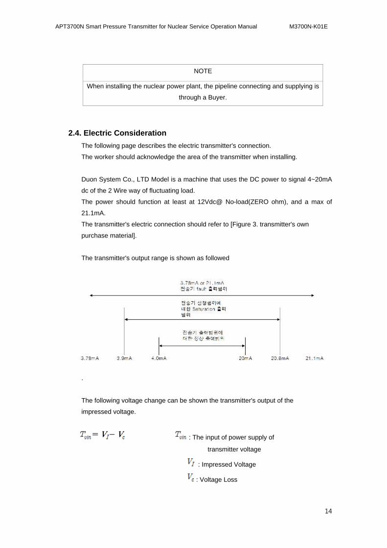
Duon System Co., LTD Model is a machine that uses the DC power to signal 4~20mA
dc of the 2 Wire way of fluctuating load.
The power should function at least at 12Vdc@ No-load(ZERO ohm), and a max of
21.1mA.
The transmitter's electric connection should refer to [Figure 3. transmitter's own
purchase material].
The transmitter's output range is shown as followed
.
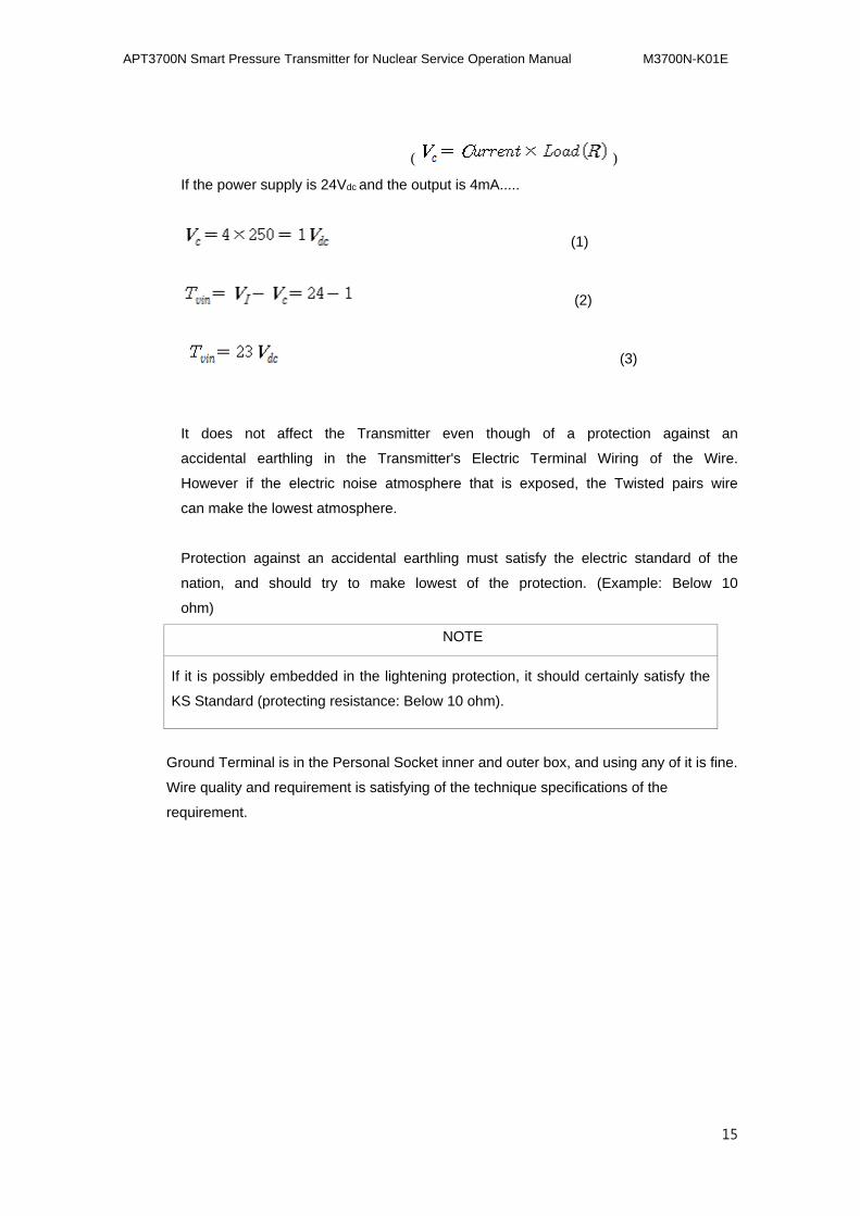
The following voltage change can be shown the transmitter's output of the
impressed voltage.
: The input of power supply of
transmitter voltage
: Impressed Voltage
: Voltage Loss
APT3700N Smart Pressure Transmitter for Nuclear Service Operation Manual M3700N-K01E
15
( )
If the power supply is 24Vdc and the output is 4mA.....
(1)
(2)
(3)
It does not affect the Transmitter even though of a protection against an
accidental earthling in the Transmitter's Electric Terminal Wiring of the Wire.
However if the electric noise atmosphere that is exposed, the Twisted pairs wire
can make the lowest atmosphere.
Protection against an accidental earthling must satisfy the electric standard of the
nation, and should try to make lowest of the protection. (Example: Below 10
ohm)
NOTE NOTE
If it is possibly embedded in the lightening protection, it should certainly satisfy the
KS Standard (protecting resistance: Below 10 ohm).
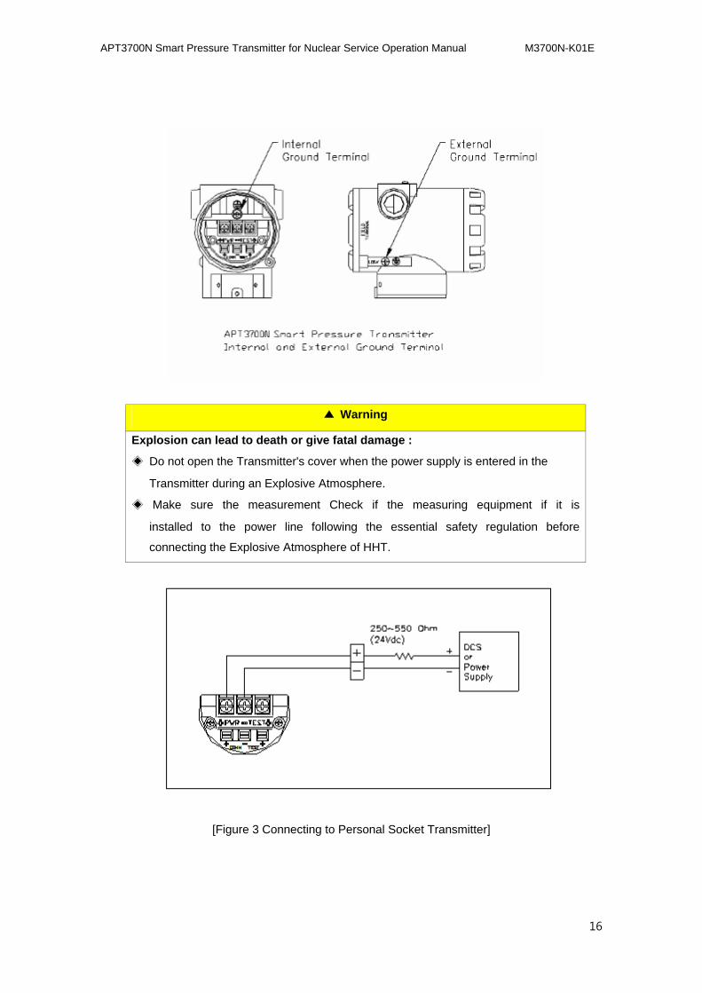
Ground Terminal is in the Personal Socket inner and outer box, and using any of it is fine.
Wire quality and requirement is satisfying of the technique specifications of the
requirement.
APT3700N Smart Pressure Transmitter for Nuclear Service Operation Manual M3700N-K01E
16
▲ Warning
Explosion can lead to death or give fatal damage :
◈ Do not open the Transmitter's cover when the power supply is entered in the
Transmitter during an Explosive Atmosphere.
◈ Make sure the measurement Check if the measuring equipment if it is
installed to the power line following the essential safety regulation before
connecting the Explosive Atmosphere of HHT.
[Figure 3 Connecting to Personal Socket Transmitter]
APT3700N Smart Pressure Transmitter for Nuclear Service Operation Manual M3700N-K01E
17
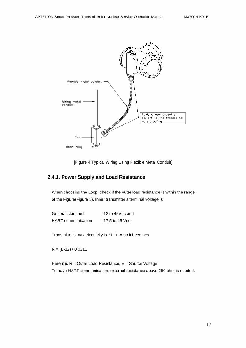
[Figure 4 Typical Wiring Using Flexible Metal Conduit]
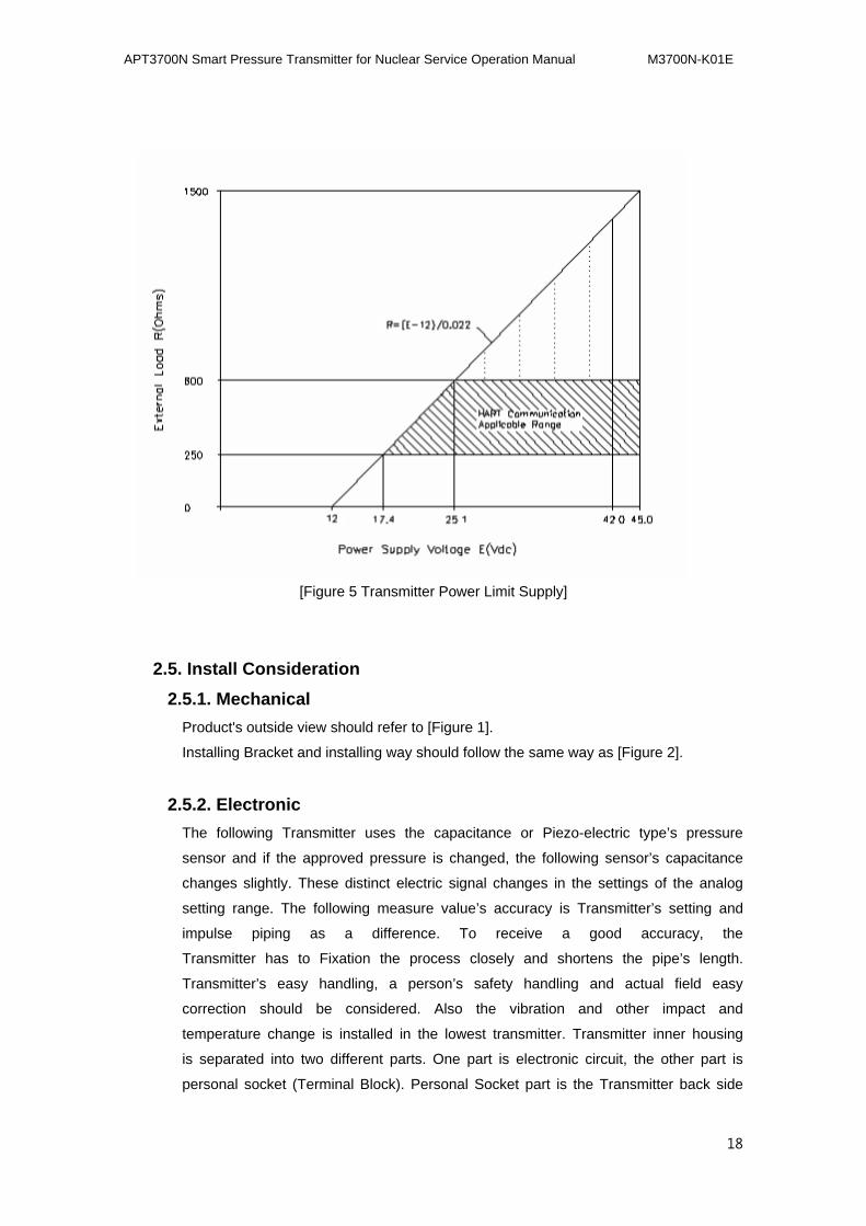
2.4.1. Power Supply and Load Resistance
When choosing the Loop, check if the outer load resistance is within the range
of the Figure(Figure 5). Inner transmitter’s terminal voltage is
General standard : 12 to 45Vdc and
HART communication : 17.5 to 45 Vdc,
Transmitter's max electricity is 21.1mA so it becomes
R = (E-12) / 0.0211
Here it is R = Outer Load Resistance, E = Source Voltage.
To have HART communication, external resistance above 250 ohm is needed.
APT3700N Smart Pressure Transmitter for Nuclear Service Operation Manual M3700N-K01E
18
[Figure 5 Transmitter Power Limit Supply]
2.5. Install Consideration
2.5.1. Mechanical
Product's outside view should refer to [Figure 1].
Installing Bracket and installing way should follow the same way as [Figure 2].
2.5.2. Electronic
The following Transmitter uses the capacitance or Piezo-electric type’s pressure
sensor and if the approved pressure is changed, the following sensor’s capacitance
changes slightly. These distinct electric signal changes in the settings of the analog
setting range. The following measure value’s accuracy is Transmitter’s setting and
impulse piping as a difference. To receive a good accuracy, the
Transmitter has to Fixation the process closely and shortens the pipe’s length.
Transmitter’s easy handling, a person’s safety handling and actual field easy
correction should be considered. Also the vibration and other impact and
temperature change is installed in the lowest transmitter. Transmitter inner housing
is separated into two different parts. One part is electronic circuit, the other part is
personal socket (Terminal Block). Personal Socket part is the Transmitter back side
APT3700N Smart Pressure Transmitter for Nuclear Service Operation Manual M3700N-K01E
19
and the Transmitter outer housing has to show “Field Terminal”. When opening
the housing cover, inside the housing cover is a transmitter Personal
Socket (Terminal Block). Transmitter’s supply power is Personal Socket’s connection
of considers the polarity. HART’s power supply configurator is connected to the
power supply terminal’s “COMM” plate. The site installed outside the Indicator can
connect to the “TEST” pin. Transmitter’s power service is terminal voltage’s entry of between 12 ~ 45V D.C.
voltage, the power service has to be below the 2% Ripple. Loop resistance is the total
resistance in the loop area and the Intrinsic Safety Barrier usage both includes the
barrier resistance.
Greatest Loop Resistance
Here, the loop resistance of HART communication is recommended of supplying
voltage when it is 24Vdc, it is between value of 250 ~ 550 Ohm.
a. Caution in the finals
Cable should be installed in the greatest capacitive transformer, motor, power supply
unit and same electric static root.
Before finishing, the electric Final Connection (Cap) should be placed.
All parts with screw pair should use the waterproof suture.
(recommended suture silicone type that does not harden and is used in the field)
To avoid material noise, duct should not be installed in both the signal line and power
line. Shield wire should be used at the material noise influence electronically.
Cable should be used that can satisfy the instrument regulation of handling the
temperature above the surrounding temperature or area in a low ground.
There is a need for wire and cable for atmosphere to handle poor gas, solvent,
corrosive gas or liquid.
b. Link Procedure
1) Open the housing cover named “FIELD TERMINAL”.
APT3700N Smart Pressure Transmitter for Nuclear Service Operation Manual M3700N-K01E
20
2) Connect the power to the “+ PWR” terminal(left terminal) “+” and connect the
power to the PWR “-“ terminal(middle terminal) “-“ . The side that is shown
“TEST” “+” terminal should not connect to the “+” power. TEST terminal’s
connectivity will damage the Test diode.
3) Housing’s Personal Socket side to prevent moisture prevention should use
the (Conduit) to stop the connecting piece.
4) Transmitter’s power supply is supplied through the (Signal Wiring) and the
common wire should not be installed near the power line and the heavy
electric machine equipment. While connecting the common wire, the signal
loop’s one side is ground connected, and the other side is not ground
connected to the other side. The power supply “-“ side should be ground
connected.
5) To connect well, the screw terminal should be strengthened.
6) Transmitter cover closes normally.
▲Warning
Do not approve High Voltage (Meaning AC Power Supply) of Transmitter terminal. It
can damage the transmitter.
7) To have HART communication’s supply voltage 24Vdc, power supply and
Transmitter’s Current Loop of 250~550 ohm’s has to connect to Loop
Resistor. Refer to Figure 3.
APT3700N Smart Pressure Transmitter for Nuclear Service Operation Manual M3700N-K01E
21
3.3. Calibration
3.1. Overview
User requirements of the measurement range and measurement way of setting is the
production setting part, and can be checked with the factory examination.
The following page is the change or process movement after installing the site or the
change or the process movement of the alteration figure.
ZERO / ZERO Adjustment / ZERO Trim
SPAN
Damping Adjustment
Button Function
Model APT3700N Series’s setting pressure range has been written in the template
HART Communicator and can be identified with communication. Setting pressure
range should change with button function of HART Communicator’s resetting.
NOTE
● HART Communicator : Handheld Terminal 275/375/475, UMPC
● Button Function : safety relation(Class 1E) can not be used with the
equipment.
Button Function is using LCD to send a message, and the safety
transmitter LCD is not installed, however ZERO adjustment and SPAN
adjustment is possible.
ZERO/SPAN’s adjustment can be divided into analog and digital concept, and the
following description article should be explained.
3.2. ZERO
It is possible to set the value 4mA to a setting function. This should adjust to a setting of
pressure range.
Example) Pressure range is 0~60psig.
APT3700N Smart Pressure Transmitter for Nuclear Service Operation Manual M3700N-K01E
22
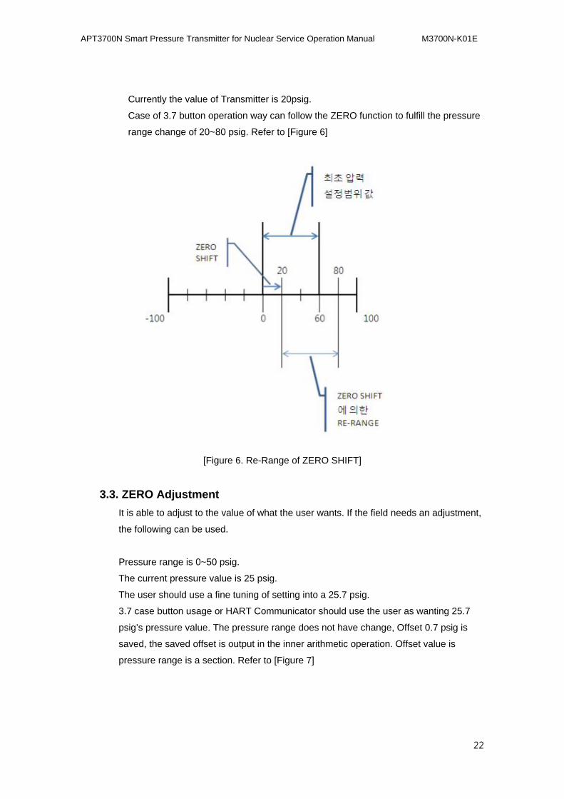
Currently the value of Transmitter is 20psig.
Case of 3.7 button operation way can follow the ZERO function to fulfill the pressure
range change of 20~80 psig. Refer to [Figure 6]
[Figure 6. Re-Range of ZERO SHIFT]
3.3. ZERO Adjustment
It is able to adjust to the value of what the user wants. If the field needs an adjustment,
the following can be used.
Pressure range is 0~50 psig.
The current pressure value is 25 psig.
The user should use a fine tuning of setting into a 25.7 psig.
3.7 case button usage or HART Communicator should use the user as wanting 25.7
psig’s pressure value. The pressure range does not have change, Offset 0.7 psig is
saved, the saved offset is output in the inner arithmetic operation. Offset value is
pressure range is a section. Refer to [Figure 7]
APT3700N Smart Pressure Transmitter for Nuclear Service Operation Manual M3700N-K01E
23
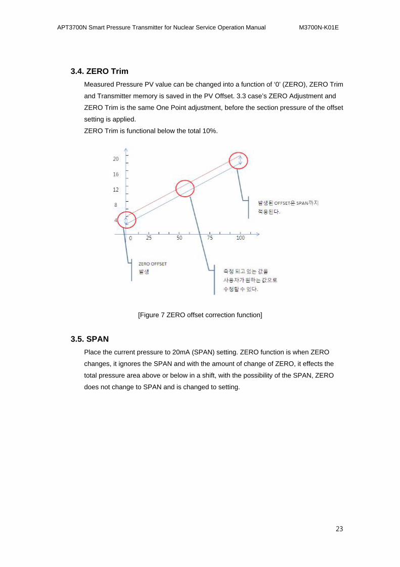
3.4. ZERO Trim
Measured Pressure PV value can be changed into a function of ‘0’ (ZERO), ZERO Trim
and Transmitter memory is saved in the PV Offset. 3.3 case’s ZERO Adjustment and
ZERO Trim is the same One Point adjustment, before the section pressure of the offset
setting is applied.
ZERO Trim is functional below the total 10%.
[Figure 7 ZERO offset correction function]
3.5. SPAN
Place the current pressure to 20mA (SPAN) setting. ZERO function is when ZERO
changes, it ignores the SPAN and with the amount of change of ZERO, it effects the
total pressure area above or below in a shift, with the possibility of the SPAN, ZERO
does not change to SPAN and is changed to setting.
APT3700N Smart Pressure Transmitter for Nuclear Service Operation Manual M3700N-K01E
24
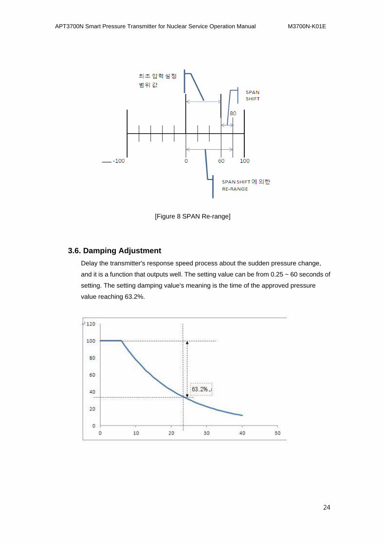
[Figure 8 SPAN Re-range]
3.6. Damping Adjustment
Delay the transmitter's response speed process about the sudden pressure change,
and it is a function that outputs well. The setting value can be from 0.25 ~ 60 seconds of
setting. The setting damping value's meaning is the time of the approved pressure
value reaching 63.2%.
APT3700N Smart Pressure Transmitter for Nuclear Service Operation Manual M3700N-K01E
25
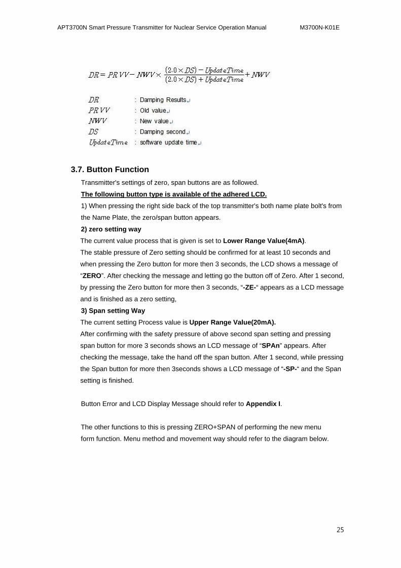
3.7. Button Function
Transmitter's settings of zero, span buttons are as followed.
The following button type is available of the adhered LCD.
1) When pressing the right side back of the top transmitter's both name plate bolt's from
the Name Plate, the zero/span button appears.
2) zero setting way
The current value process that is given is set to Lower Range Value(4mA).
The stable pressure of Zero setting should be confirmed for at least 10 seconds and
when pressing the Zero button for more then 3 seconds, the LCD shows a message of
“ZERO”. After checking the message and letting go the button off of Zero. After 1 second,
by pressing the Zero button for more then 3 seconds, “-ZE-“ appears as a LCD message
and is finished as a zero setting,
3) Span setting Way
The current setting Process value is Upper Range Value(20mA).
After confirming with the safety pressure of above second span setting and pressing
span button for more 3 seconds shows an LCD message of “SPAn” appears. After
checking the message, take the hand off the span button. After 1 second, while pressing
the Span button for more then 3seconds shows a LCD message of “-SP-“ and the Span
setting is finished.
Button Error and LCD Display Message should refer to Appendix I.
The other functions to this is pressing ZERO+SPAN of performing the new menu
form function. Menu method and movement way should refer to the diagram below.
APT3700N Smart Pressure Transmitter for Nuclear Service Operation Manual M3700N-K01E
26
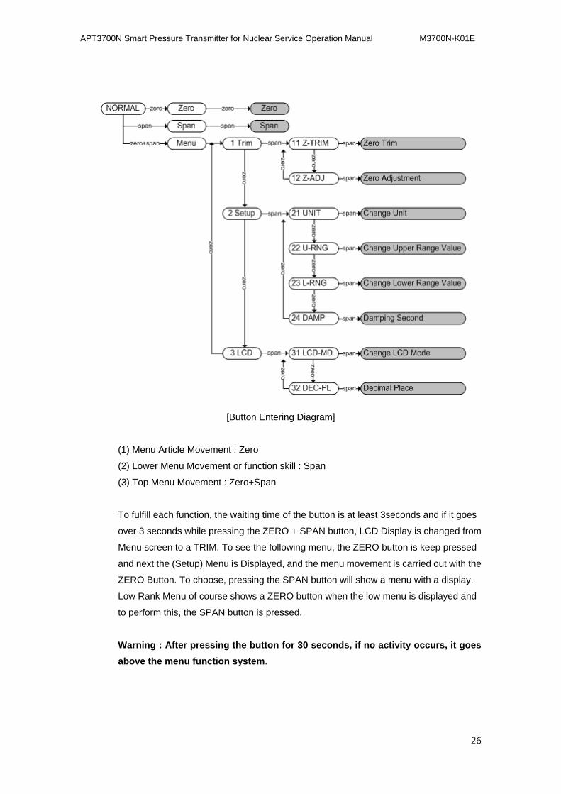
[Button Entering Diagram]
(1) Menu Article Movement : Zero
(2) Lower Menu Movement or function skill : Span
(3) Top Menu Movement : Zero+Span
To fulfill each function, the waiting time of the button is at least 3seconds and if it goes
over 3 seconds while pressing the ZERO + SPAN button, LCD Display is changed from
Menu screen to a TRIM. To see the following menu, the ZERO button is keep pressed
and next the (Setup) Menu is Displayed, and the menu movement is carried out with the
ZERO Button. To choose, pressing the SPAN button will show a menu with a display.
Low Rank Menu of course shows a ZERO button when the low menu is displayed and
to perform this, the SPAN button is pressed.
Warning : After pressing the button for 30 seconds, if no activity occurs, it goes
above the menu function system.
APT3700N Smart Pressure Transmitter for Nuclear Service Operation Manual M3700N-K01E
27
Step Recording Way
(1) Step Recording needs function : 12 Zero Adjustment, 22 Change Upper Range
Value, 23 Change Lower Range Value, 24 Damping Second functions needs
functions of step recording.
(2) Step Recording Way : First select the Addition(10n) and after changing the desired
value of Increase/decrease of changing value.
(3) For example of inserting 3810 : select 1000 increase -> increase 1000 3 times ->
select 100 increase -> increase 100 per 8 -> select 10 increase -> 10 times increase per
1
(4) Increase, Decrease Step selection : Message of SelInc is shown at the button of
LCD. Select Step with Zero Button : While pressing the Zero button, 10unit is changed.
After having a step setting, the span button should be pressed of performing 2 times.
(5) Zero, Span wants a value setting change : the bottom LCD has a VALUE message
shown When pressing the Zero button should increase the setting clause in an increase
Step When pressing the Span, the setting step decreases from the 1st clause After
hanging to a value wanted, Zero+Span button should be pressed to carry out the 1st
clause.
(6) Repeat the forward number (4) and (5) of the desired value setting finally in the
value of desire value in the finished setting of fulfilling number(4)of the Zero+Span
button of finishing the input procedure.
Function Accompanying Performance
ZERO TRIM
- Press the ZERO+SPAN button and perform the pressing menu.
- When the 1 TRIM message is shown, the SPAN button should be pressed to
move to the lower menu.
- If the 11 Z-TRIM message is shown, the SPAN button is pressed to function
ZERO TRIM.
- Zero Adjustment : PV should be revised to 14
- ZERO+SPAN button is pressed to execute the menu
- 1 TRIM message is shown, the span button is pressed to move to the lower
menu.
- If 11 Z-TRIM message is shown, the Zero button is pressed to change menu.
- If 12 Z-ADJ message is shown, press the San button to perform the Zero
Adjustment.
- If the SelInc message is shown, the expression of LCD 10.0 presses the Zero
button repeatedly and if the LCD shows 10.0, Span button is pressed to revise
APT3700N Smart Pressure Transmitter for Nuclear Service Operation Manual M3700N-K01E
28
the Value.
- When the VALUE message is shown, the Zero button should be pressed once
to change the LCD displayed value to 10.0 and press the Zero+Span later.
- If the SelInc message is shown, the LCD of 1.0 indicator will press the Zero
button repeatedly to indicate the LCD of 1.0 Span revised Value button.
If the VALUE message is shown, the Zero button should be pressed 4 times to a
LCD displayed changed value of 14.0 and press the Zero+Span button
- If the SelInc message is shown, the Zero+Span button is pressed to save the
setting value
Change Unit
- Zero+Span button is pressed to activate the Menu.
- If 1 TRIM message is indicated press the Zero button to change.
- If 2 SETUP message is indicated, press the span button to move to the lower
menu.
- 21 UNIT message is indicated of pressing San button of performing Change Unit
function.
- Until the lower LCD shows a unit is shown, the zero buttons should be pressed
rapidly to show the Unit that wants to be indicated by pressing the Span button
of saving the setting value
Change Upper Range Value
- Press the Zero+Span button to process the Menu
- If 1 TRIM message is indicated press the Zero button to change.
- If 2 SETUP message is indicated, press the span button to move to the lower
menu.
- 21 UNIT message is indicated Zero button of moving to menu.
- 22 U-RNG message is indicated Span button pressing of performing function.
- Step Recording Way is same as Zero Adjustment
Change Lower Range Value
- Zero+Span button is pressed to perform Menu
- 1 TRIM message is indicated Zero button pressing to move menu
- 2 SETUP message is indicated Span button pressing to move to lower menu
- 21 UNIT message is indicated Zero button pressing to move menu
- 22 U-RNG message is indicated Zero button pressing to move menu
- 23 L-RNG message is indicated Span button pressing to move to perform function
- Step Recording Way is the same as Zero Adjustment
APT3700N Smart Pressure Transmitter for Nuclear Service Operation Manual M3700N-K01E
29
Change LCD Mode
- Zero+Span button should be pressed to activate Menu
- 1 TRIM message is indicated Zero button pressing to move menu
- 2 SETUP message is indicated Zero button pressing to move menu
- 3 LCD message is indicated Span button pressing to move to lower menu
- 31 LCD-MD message is indicated Span button pressing to move to perform
function
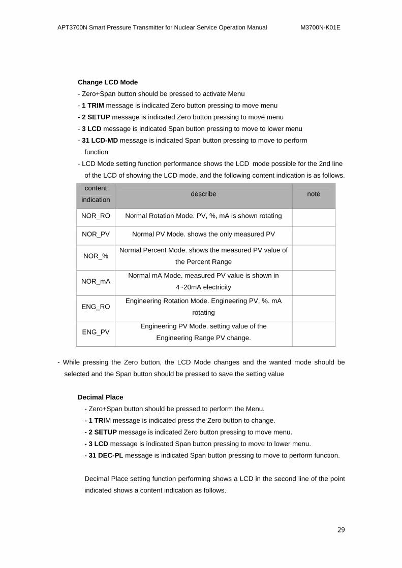
- LCD Mode setting function performance shows the LCD mode possible for the 2nd line
of the LCD of showing the LCD mode, and the following content indication is as follows.
content
indication describe note
NOR_RO Normal Rotation Mode. PV, %, mA is shown rotating
NOR_PV Normal PV Mode. shows the only measured PV
NOR_% Normal Percent Mode. shows the measured PV value of
the Percent Range
NOR_mA Normal mA Mode. measured PV value is shown in
4~20mA electricity
ENG_RO Engineering Rotation Mode. Engineering PV, %. mA
rotating
ENG_PV Engineering PV Mode. setting value of the
Engineering Range PV change.
- While pressing the Zero button, the LCD Mode changes and the wanted mode should be
selected and the Span button should be pressed to save the setting value
Decimal Place
- Zero+Span button should be pressed to perform the Menu.
- 1 TRIM message is indicated press the Zero button to change.
- 2 SETUP message is indicated Zero button pressing to move menu.
- 3 LCD message is indicated Span button pressing to move to lower menu.
- 31 DEC-PL message is indicated Span button pressing to move to perform function.
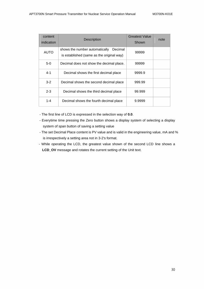
Decimal Place setting function performing shows a LCD in the second line of the point
indicated shows a content indication as follows.
APT3700N Smart Pressure Transmitter for Nuclear Service Operation Manual M3700N-K01E
30
content
indication Description
Greatest Value
Shown note
AUTO shows the number automatically Decimal
is established (same as the original way) 99999
5-0 Decimal does not show the decimal place. 99999
4-1 Decimal shows the first decimal place 9999.9
3-2 Decimal shows the second decimal place 999.99
2-3 Decimal shows the third decimal place 99.999
1-4 Decimal shows the fourth decimal place 9.9999
- The first line of LCD is expressed in the selection way of 0.0.
- Everytime time pressing the Zero button shows a display system of selecting a display
system of span button of saving a setting value
- The set Decimal Place content is PV value and is valid in the engineering value, mA and %
is irrespectively a setting area not in 3-2's format.
- While operating the LCD, the greatest value shown of the second LCD line shows a
LCD_OV message and rotates the current setting of the Unit text.
APT3700N Smart Pressure Transmitter for Nuclear Service Operation Manual M3700N-K01E
31
4.4. OPERATION
4.1. Overview
The following page has a basic smart Transmitter's movement in the following
content below.
● Transmitter Operation & Sensor
● Transmitter's greatest output current
● Protecting the side power supply injection
● Installation Place
● condition of beginning movement
● connection of the pressure
● Limit of the wireless transmitter
APT3700N Smart Pressure Transmitter for Nuclear Service Operation Manual M3700N-K01E
32
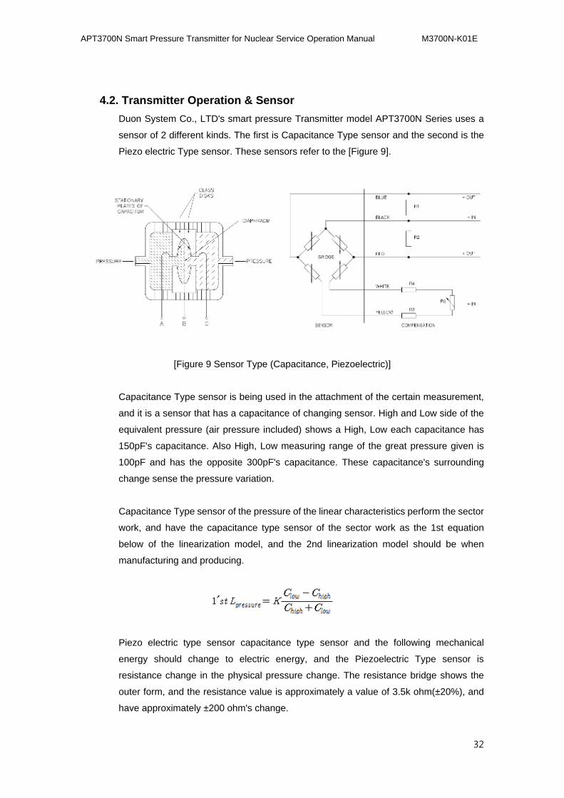
4.2. Transmitter Operation & Sensor
Duon System Co., LTD's smart pressure Transmitter model APT3700N Series uses a
sensor of 2 different kinds. The first is Capacitance Type sensor and the second is the
Piezo electric Type sensor. These sensors refer to the [Figure 9].
[Figure 9 Sensor Type (Capacitance, Piezoelectric)]
Capacitance Type sensor is being used in the attachment of the certain measurement,
and it is a sensor that has a capacitance of changing sensor. High and Low side of the
equivalent pressure (air pressure included) shows a High, Low each capacitance has
150pF's capacitance. Also High, Low measuring range of the great pressure given is
100pF and has the opposite 300pF's capacitance. These capacitance's surrounding
change sense the pressure variation.
Capacitance Type sensor of the pressure of the linear characteristics perform the sector
work, and have the capacitance type sensor of the sector work as the 1st equation
below of the linearization model, and the 2nd linearization model should be when
manufacturing and producing.
Piezo electric type sensor capacitance type sensor and the following mechanical
energy should change to electric energy, and the Piezoelectric Type sensor is
resistance change in the physical pressure change. The resistance bridge shows the
outer form, and the resistance value is approximately a value of 3.5k ohm(±20%), and
have approximately ±200 ohm's change.
APT3700N Smart Pressure Transmitter for Nuclear Service Operation Manual M3700N-K01E
33
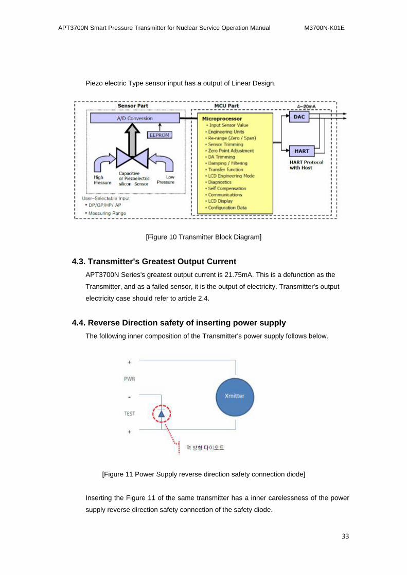
Piezo electric Type sensor input has a output of Linear Design.
[Figure 10 Transmitter Block Diagram]
4.3. Transmitter's Greatest Output Current
APT3700N Series's greatest output current is 21.75mA. This is a defunction as the
Transmitter, and as a failed sensor, it is the output of electricity. Transmitter's output
electricity case should refer to article 2.4.
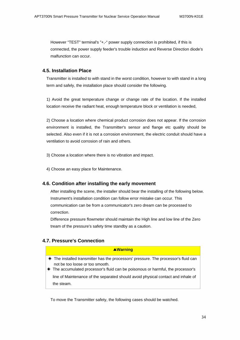
4.4. Reverse Direction safety of inserting power supply
The following inner composition of the Transmitter's power supply follows below.
[Figure 11 Power Supply reverse direction safety connection diode]
Inserting the Figure 11 of the same transmitter has a inner carelessness of the power
supply reverse direction safety connection of the safety diode.
APT3700N Smart Pressure Transmitter for Nuclear Service Operation Manual M3700N-K01E
34
However “TEST" terminal's ”+,-“ power supply connection is prohibited, if this is
connected, the power supply feeder's trouble induction and Reverse Direction diode's
malfunction can occur.
4.5. Installation Place
Transmitter is installed to with stand in the worst condition, however to with stand in a long
term and safely, the installation place should consider the following.
1) Avoid the great temperature change or change rate of the location. If the installed
location receive the radiant heat, enough temperature block or ventilation is needed,
2) Choose a location where chemical product corrosion does not appear. If the corrosion
environment is installed, the Transmitter's sensor and flange etc quality should be
selected. Also even if it is not a corrosion environment, the electric conduit should have a
ventilation to avoid corrosion of rain and others.
3) Choose a location where there is no vibration and impact.
4) Choose an easy place for Maintenance.
4.6. Condition after installing the early movement
After installing the scene, the installer should bear the installing of the following below.
Instrument's installation condition can follow error mistake can occur. This
communication can be from a communicator's zero dream can be processed to
correction.
Difference pressure flowmeter should maintain the High line and low line of the Zero
tream of the pressure's safety time standby as a caution.
4.7. Pressure's Connection
▲Warning
◈ The installed transmitter has the processors' pressure. The processor's fluid can not be too loose or too smooth.
◈ The accumulated processor's fluid can be poisonous or harmful, the processor's
line of Maintenance of the separated should avoid physical contact and inhale of
the steam.
To move the Transmitter safety, the following cases should be watched.
APT3700N Smart Pressure Transmitter for Nuclear Service Operation Manual M3700N-K01E
35
1) Working Pressure of the high pressure should not be approved.
2) Transmitter's pressure connection specifications should be checked of the
standard or quality of the material.
3) Poor inadequate atmosphere or the regulation requirement should be leaked and
have a sealing arrangement.
4.8. Restricted Transmitter
▲Warning
◈ Transmitter is installed to handle a high frequency of electric noise,
when using the radio Transmitter or a Transmitter's outer wiring can
show an effect in the transmitter of the high frequency noise. To test
these influence, the transmitter should be observed from the transmitter
from a far distance slowly.
After this, transmitter should always be used outside the noise's
influence.
APT3700N Smart Pressure Transmitter for Nuclear Service Operation Manual M3700N-K01E
36
5.5. Maintenance and Troubleshooting
5.1. Overview
The following pages are providing a guide for the managing method of components for
transmitter and the troubleshooting.
5.2. Safety Message
The following page of the content procedure and work directions needs special caution
for the user's safety. The ones with special Safety because of the danger is shown in a
mark of an alarm display (▲). When following this display, it should refer to the safety
message of performing operations.
▲Warning
Explosion can lead to death and fatal damage
◈ When the power energy has been inserted to the transmitter, the explosive
Atmospheres should not open the cover of the transmitter's cover.
◈ In the atmosphere of the explosiveness, checking the power line of the
measuring instruments of the HHT with the intrinsic safety regulations
▲Warning
Not following this installation procedure can lead to death or a fatal wound.
◈ Only a person with the education can install the transmitter.
▲Warning
Electric impact can lead to death and fatal wound.
◈ Power line and terminal contact should be avoided. Lead line can lead to a
shock in the high voltage shock.
APT3700N Smart Pressure Transmitter for Nuclear Service Operation Manual M3700N-K01E
37
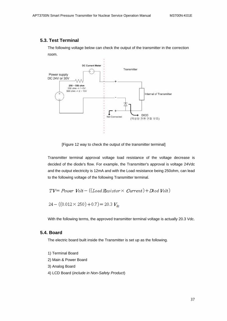
5.3. Test Terminal
The following voltage below can check the output of the transmitter in the correction
room.
[Figure 12 way to check the output of the transmitter terminal]
Transmitter terminal approval voltage load resistance of the voltage decrease is
decided of the diode's flow. For example, the Transmitter's approval is voltage 24Vdc
and the output electricity is 12mA and with the Load resistance being 250ohm, can lead
to the following voltage of the following Transmitter terminal.
With the following terms, the approved transmitter terminal voltage is actually 20.3 Vdc.
5.4. Board
The electric board built inside the Transmitter is set up as the following.
1) Terminal Board
2) Main & Power Board
3) Analog Board
4) LCD Board (include in Non-Safety Product)
APT3700N Smart Pressure Transmitter for Nuclear Service Operation Manual M3700N-K01E
38
The terminal board of the Transmitter input of the power supply is composed of the 2nd
noise filter. Power supply and high frequency noise's parts are removed from the 1, 2nd
filter. 1st filter is connected to the terminal block and terminal board of the attached EMI
filter.
Terminal board has a fixed housing in the housing, however it can not replace just the
terminal board. So the above terminal board should be handled with the housing
change.
The main and power board has 1,2nd filtering of the power supply of the inner
semiconductor of the filter of creating (3.3 Vdc), processing a pressured value using a
micro controller to measure it.
Main and power board is easy to dissemble and assemble, however when exchanging
with a new board, the parameter has to be reset.
Analog board has a sensor's change should change to a main board’s mike to control
easily, and send with the micro controller.
Analog board is fixed in the sensor module so just exchanging the terminal board is
impossible. The memory inside the analog board has insertion of the transmitter
manufacturer so the analog board's sensor body should be exchanged.
LCD board Safety-Related equipment does not apply.
LCD board Non-Safety-Related equipment does not function, and Transmitter’s
measured value can decipher and display in the field.
LCD board and dissemble and reassemble is easy.
5.5. Maintenance
Also APT3700N Series Transmitter is installed in a function unit that is easy to
Maintenance. It if seems to malfunction, check should be made to see if there is an
outside error before the program of error diagnosis is run.
5.5.1. Test Terminal
There is a test terminal named Personal Socket as a Test. Test terminal and power line
Loop (-) terminal is connected to the each side of the power supply line.
Normally it is following through the Loop current diode.
APT3700N Smart Pressure Transmitter for Nuclear Service Operation Manual M3700N-K01E
39
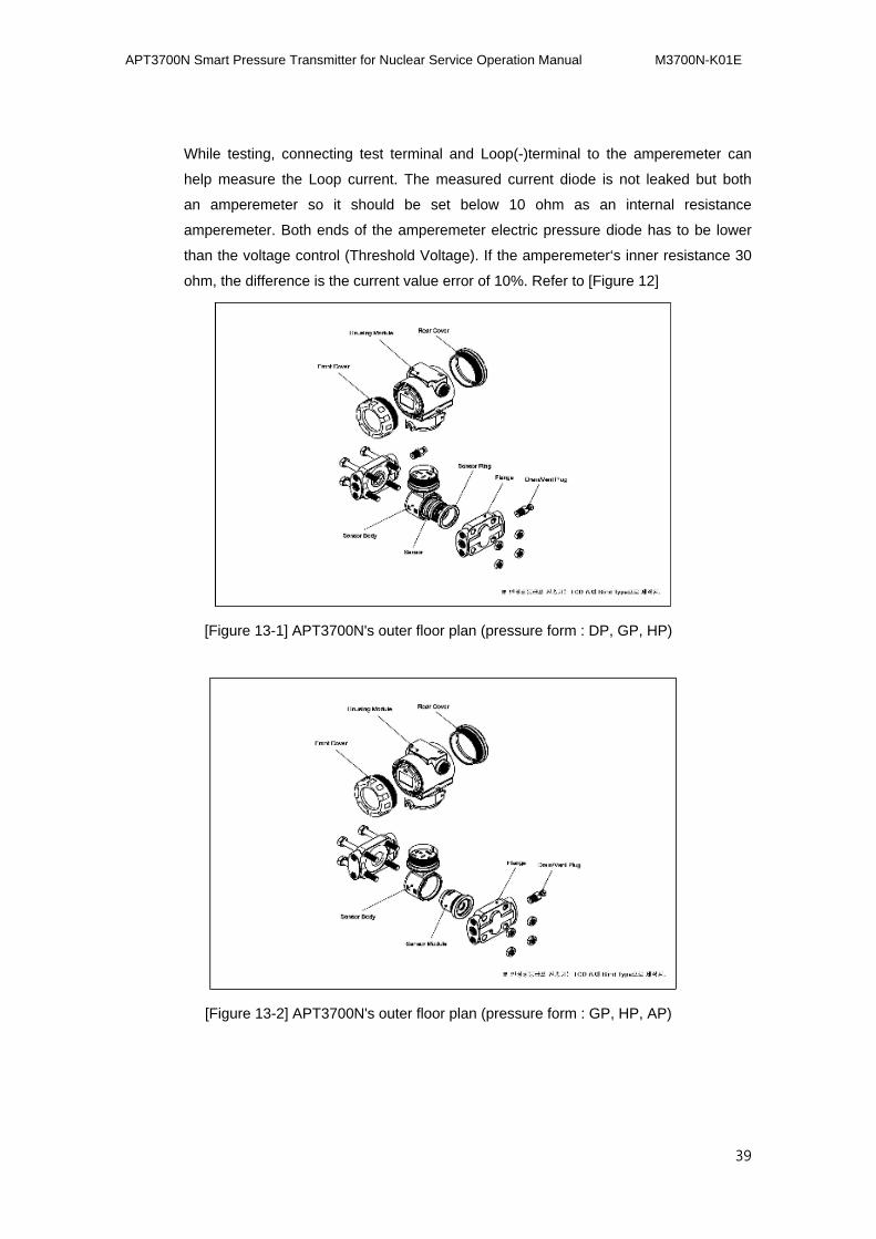
While testing, connecting test terminal and Loop(-)terminal to the amperemeter can
help measure the Loop current. The measured current diode is not leaked but both
an amperemeter so it should be set below 10 ohm as an internal resistance
amperemeter. Both ends of the amperemeter electric pressure diode has to be lower
than the voltage control (Threshold Voltage). If the amperemeter‘s inner resistance 30
ohm, the difference is the current value error of 10%. Refer to [Figure 12]
[Figure 13-1] APT3700N's outer floor plan (pressure form : DP, GP, HP)
[Figure 13-2] APT3700N's outer floor plan (pressure form : GP, HP, AP)
APT3700N Smart Pressure Transmitter for Nuclear Service Operation Manual M3700N-K01E
40
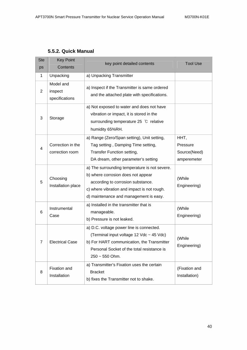
5.5.2. Quick Manual
Ste
ps
Key Point
Contents key point detailed contents Tool Use
1 Unpacking a) Unpacking Transmitter
2
Model and
inspect
specifications
a) Inspect if the Transmitter is same ordered
and the attached plate with specifications.
3 Storage
a) Not exposed to water and does not have
vibration or impact, it is stored in the
surrounding temperature 25 ℃ relative
humidity 65%RH.
4 Correction in the
correction room
a) Range (Zero/Span setting), Unit setting,
Tag setting , Damping Time setting,
Transfer Function setting,
DA dream, other parameter’s setting
HHT,
Pressure
Source(Need)
amperemeter
5 Choosing
Installation place
a) The surrounding temperature is not severe.
b) where corrosion does not appear
according to corrosion substance.
c) where vibration and impact is not rough.
d) maintenance and management is easy.
(While
Engineering)
6 Instrumental
Case
a) Installed in the transmitter that is
manageable.
b) Pressure is not leaked.
(While
Engineering)
7 Electrical Case
a) D.C. voltage power line is connected.
(Terminal input voltage 12 Vdc ~ 45 Vdc)
b) For HART communication, the Transmitter
Personal Socket of the total resistance is
250 ~ 550 Ohm.
(While
Engineering)
8 Fixation and
Installation
a) Transmitter’s Fixation uses the certain
Bracket
b) fixes the Transmitter not to shake.
(Fixation and
Installation)
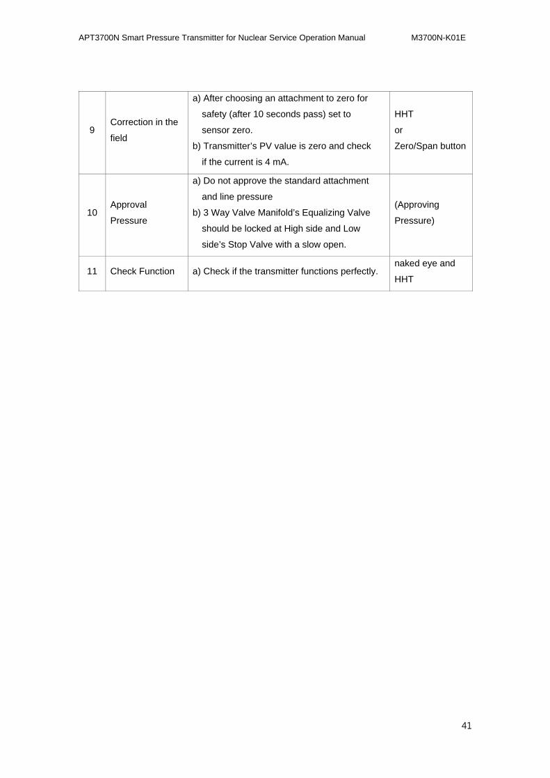
APT3700N Smart Pressure Transmitter for Nuclear Service Operation Manual M3700N-K01E
41
9 Correction in the
field
a) After choosing an attachment to zero for
safety (after 10 seconds pass) set to
sensor zero.
b) Transmitter’s PV value is zero and check
if the current is 4 mA.
HHT
or
Zero/Span button
10 Approval
Pressure
a) Do not approve the standard attachment
and line pressure
b) 3 Way Valve Manifold’s Equalizing Valve
should be locked at High side and Low
side’s Stop Valve with a slow open.
(Approving
Pressure)
11 Check Function a) Check if the transmitter functions perfectly. naked eye and
HHT
APT3700N Smart Pressure Transmitter for Nuclear Service Operation Manual M3700N-K01E
42
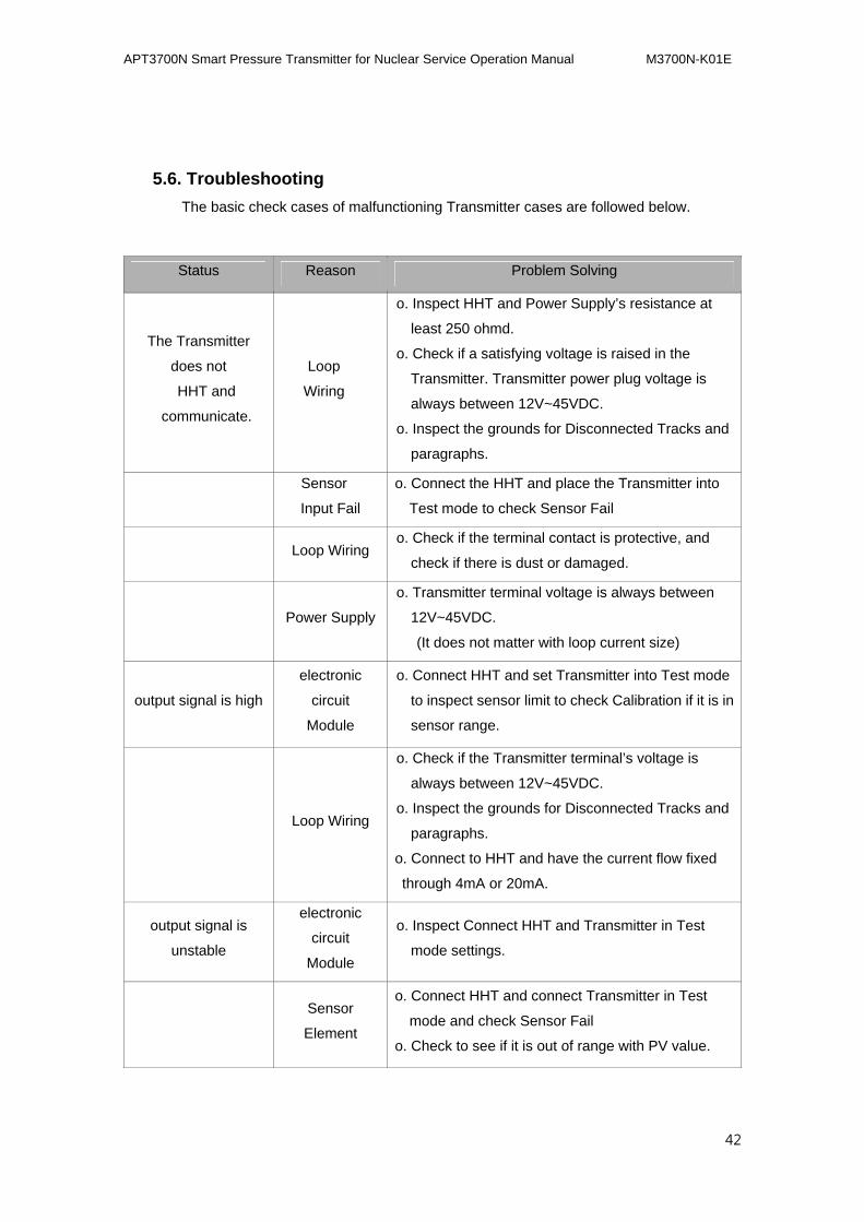
5.6. Troubleshooting
The basic check cases of malfunctioning Transmitter cases are followed below.
Status Reason Problem Solving
The Transmitter
does not
HHT and
communicate.
Loop
Wiring
o. Inspect HHT and Power Supply’s resistance at
least 250 ohmd.
o. Check if a satisfying voltage is raised in the
Transmitter. Transmitter power plug voltage is
always between 12V~45VDC.
o. Inspect the grounds for Disconnected Tracks and
paragraphs.
Sensor
Input Fail
o. Connect the HHT and place the Transmitter into
Test mode to check Sensor Fail
Loop Wiring o. Check if the terminal contact is protective, and
check if there is dust or damaged.
Power Supply
o. Transmitter terminal voltage is always between
12V~45VDC.
(It does not matter with loop current size)
output signal is high
electronic
circuit
Module
o. Connect HHT and set Transmitter into Test mode
to inspect sensor limit to check Calibration if it is in
sensor range.
Loop Wiring
o. Check if the Transmitter terminal’s voltage is
always between 12V~45VDC.
o. Inspect the grounds for Disconnected Tracks and
paragraphs.
o. Connect to HHT and have the current flow fixed
through 4mA or 20mA.
output signal is
unstable
electronic
circuit
Module
o. Inspect Connect HHT and Transmitter in Test
mode settings.
Sensor
Element
o. Connect HHT and connect Transmitter in Test
mode and check Sensor Fail
o. Check to see if it is out of range with PV value.
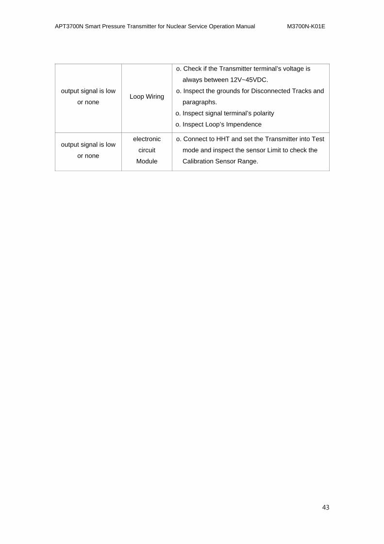
APT3700N Smart Pressure Transmitter for Nuclear Service Operation Manual M3700N-K01E
43
output signal is low
or none Loop Wiring
o. Check if the Transmitter terminal’s voltage is
always between 12V~45VDC.
o. Inspect the grounds for Disconnected Tracks and
paragraphs.
o. Inspect signal terminal’s polarity
o. Inspect Loop’s Impendence
output signal is low
or none
electronic
circuit
Module
o. Connect to HHT and set the Transmitter into Test
mode and inspect the sensor Limit to check the
Calibration Sensor Range.
APT3700N Smart Pressure Transmitter for Nuclear Service Operation Manual M3700N-K01E
44
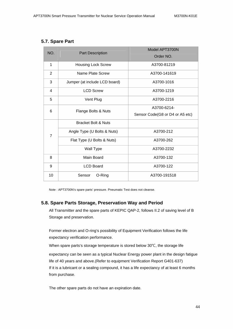
5.7. Spare Part
NO. Part Description Model APT3700N
Order NO.
1 Housing Lock Screw A3700-81219
2 Name Plate Screw A3700-141619
3 Jumper (at include LCD board) A3700-1016
4 LCD Screw A3700-1219
5 Vent Plug A3700-2216
6 Flange Bolts & Nuts A3700-6214-
Sensor Code(G8 or D4 or A5 etc)
7
Bracket Bolt & Nuts
Angle Type (U Bolts & Nuts) A3700-212
Flat Type (U Bolts & Nuts) A3700-262
Wall Type A3700-2232
8 Main Board A3700-132
9 LCD Board A3700-122
10 Sensor O-Ring A3700-191518
Note : APT3700N’s spare parts’ pressure. Pneumatic Test does not cleanse.
5.8. Spare Parts Storage, Preservation Way and Period
All Transmitter and the spare parts of KEPIC QAP-2, follows II.2 of saving level of B
Storage and preservation.
Former electron and O-ring‘s possibility of Equipment Verification follows the life
expectancy verification performance.
When spare parts‘s storage temperature is stored below 30℃, the storage life
expectancy can be seen as a typical Nuclear Energy power plant in the design fatigue
life of 40 years and above.(Refer to equipment Verification Report G401-637)
If it is a lubricant or a sealing compound, it has a life expectancy of at least 6 months
from purchase.
The other spare parts do not have an expiration date.
APT3700N Smart Pressure Transmitter for Nuclear Service Operation Manual M3700N-K01E
45
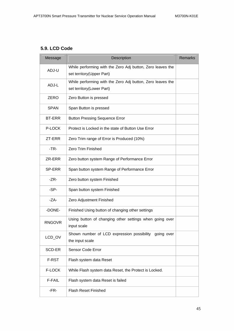
5.9. LCD Code
Message Description Remarks
ADJ-U While performing with the Zero Adj button, Zero leaves the
set territory(Upper Part)
ADJ-L While performing with the Zero Adj button, Zero leaves the
set territory(Lower Part)
ZERO Zero Button is pressed
SPAN Span Button is pressed
BT-ERR Button Pressing Sequence Error
P-LOCK Protect is Locked in the state of Button Use Error
ZT-ERR Zero Trim range of Error is Produced (10%)
-TR- Zero Trim Finished
ZR-ERR Zero button system Range of Performance Error
SP-ERR Span button system Range of Performance Error
-ZR- Zero button system Finished
-SP- Span button system Finished
-ZA- Zero Adjustment Finished
-DONE- Finished Using button of changing other settings
RNGOVR Using button of changing other settings when going over
input scale
LCD_OV Shown number of LCD expression possibility going over
the input scale
SCD-ER Sensor Code Error
F-RST Flash system data Reset
F-LOCK While Flash system data Reset, the Protect is Locked.
F-FAIL Flash system data Reset is failed
-FR- Flash Reset Finished
APT3700N Smart Pressure Transmitter for Nuclear Service Operation Manual M3700N-K01E
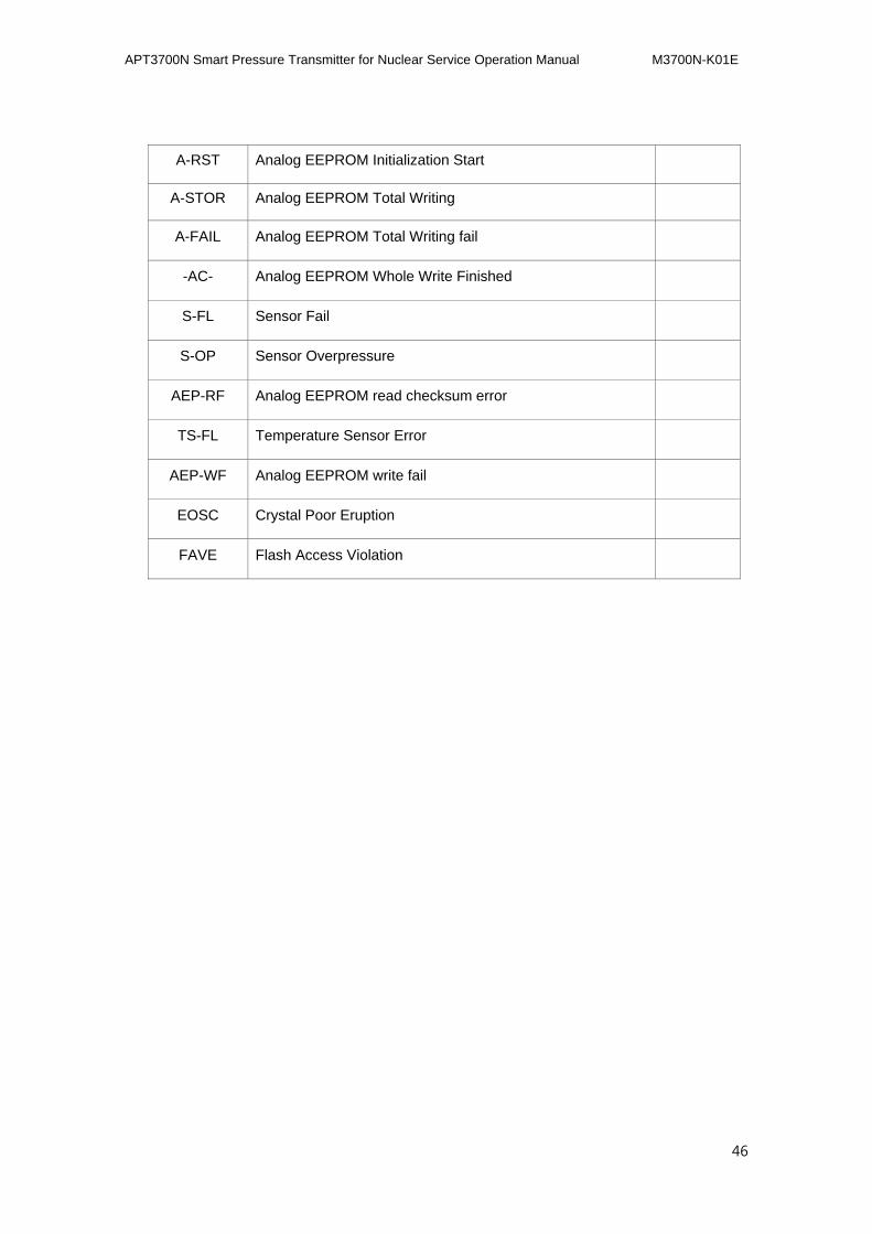
46
A-RST Analog EEPROM Initialization Start
A-STOR Analog EEPROM Total Writing
A-FAIL Analog EEPROM Total Writing fail
-AC- Analog EEPROM Whole Write Finished
S-FL Sensor Fail
S-OP Sensor Overpressure
AEP-RF Analog EEPROM read checksum error
TS-FL Temperature Sensor Error
AEP-WF Analog EEPROM write fail
EOSC Crystal Poor Eruption
FAVE Flash Access Violation
APT3700N Smart Pressure Transmitter for Nuclear Service Operation Manual M3700N-K01E
47
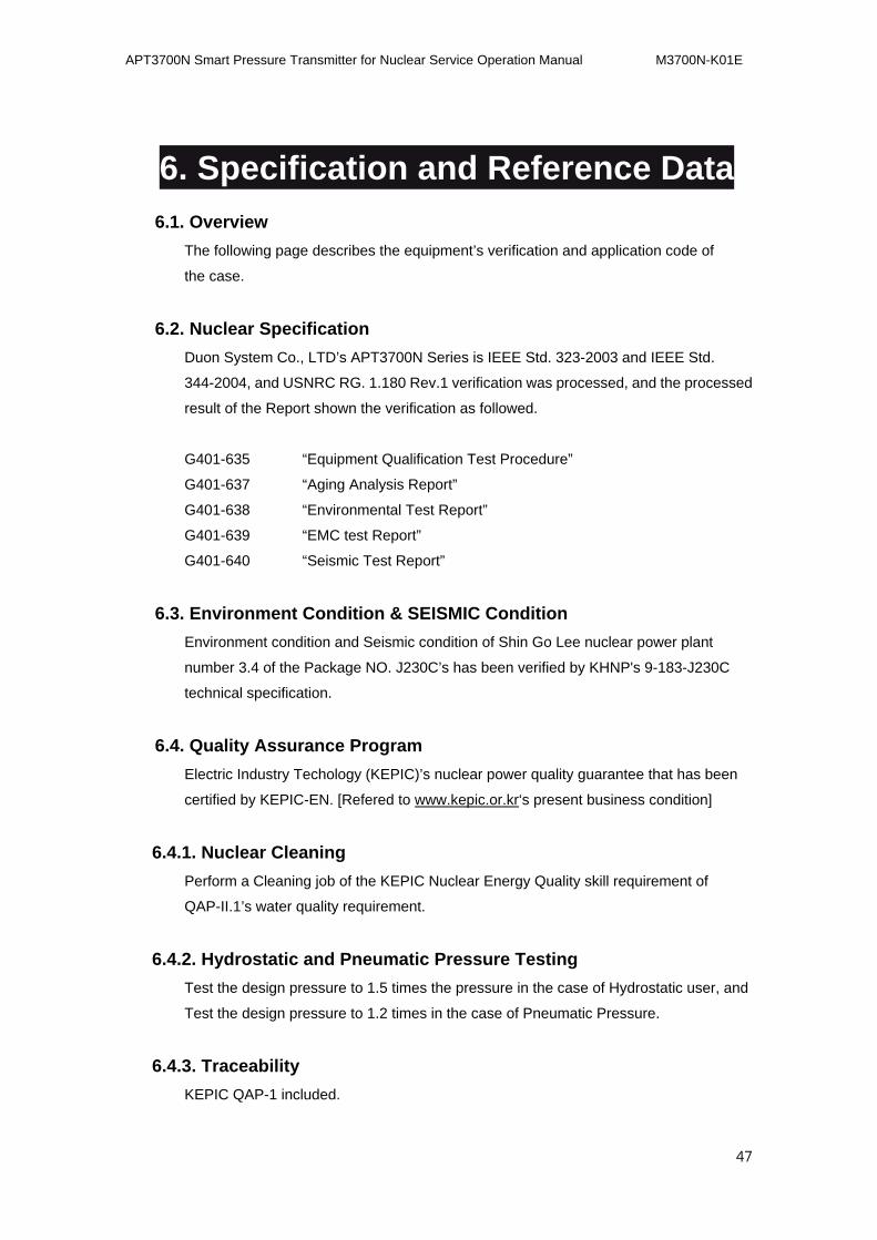
6.6. Specification and Reference Data
6.1. Overview
The following page describes the equipment’s verification and application code of
the case.
6.2. Nuclear Specification
Duon System Co., LTD’s APT3700N Series is IEEE Std. 323-2003 and IEEE Std.
344-2004, and USNRC RG. 1.180 Rev.1 verification was processed, and the processed
result of the Report shown the verification as followed.
G401-635 “Equipment Qualification Test Procedure”
G401-637 “Aging Analysis Report”
G401-638 “Environmental Test Report”
G401-639 “EMC test Report”
G401-640 “Seismic Test Report”
6.3. Environment Condition & SEISMIC Condition
Environment condition and Seismic condition of Shin Go Lee nuclear power plant
number 3.4 of the Package NO. J230C’s has been verified by KHNP's 9-183-J230C
technical specification.
6.4. Quality Assurance Program
Electric Industry Techology (KEPIC)’s nuclear power quality guarantee that has been
certified by KEPIC-EN. [Refered to www.kepic.or.kr‘s present business condition]
6.4.1. Nuclear Cleaning
Perform a Cleaning job of the KEPIC Nuclear Energy Quality skill requirement of
QAP-II.1’s water quality requirement.
6.4.2. Hydrostatic and Pneumatic Pressure Testing
Test the design pressure to 1.5 times the pressure in the case of Hydrostatic user, and
Test the design pressure to 1.2 times in the case of Pneumatic Pressure.
6.4.3. Traceability
KEPIC QAP-1 included.
APT3700N Smart Pressure Transmitter for Nuclear Service Operation Manual M3700N-K01E
48
Transmitter’s pressure related part of the quality material should use ASTM standard.
6.4.4. Qualified Life
Duon System Co.,LTD operation manual should use the Transmitter's surrounding
atmosphere of surrounding reference G401-635 , G401-637, G401-638.
6.5. Performance Specification
Accuracy
±0.075% of Calibration Span (Linearity, Hysteresis, Repeatability is included).
Dead Band
None (Able to set user)
Stability
±0.125% URL for 12 Months
Temperature Effect
±[0.019%URL+0.125% Span] / 28 ℃
Power Supply & Load Requir
Transmitters operate on 12 to 45 V dc.
* 250 ohm load-- 17.4 Vdc
* up to a 550 ohm load -- 24 Vdc
Max. Loop Resistance = ( E - 11.9 ) / 0.022
(E = Power Supply Voltage)
Loop Load
0 ~ 1500 ohm -- Operation
250 ~ 550 ohm -- HART Communications
Power supply Effect
APT3700N Smart Pressure Transmitter for Nuclear Service Operation Manual M3700N-K01E
49
±0.005% of Span per Volt
Static Pressure Effects
ZERO : ±0.1% of URL Per 7MPa
SPAN : ±0.2% of reading per 7MPa
Mounting Position Effects
ZERO Shift up to 350Pa No SPAN Effect
6.6. Functional Specification
Service Liquid, gas
Output
Analog 4 to 20 mA dc and Digital HART Communication
Power supply
12.0 ~ 45 Vdc -- operation
17.4 ~ 45 Vdc -- HART Communications
SPAN and ZERO
Using a button (Non-Safety Related Equipment)
HART Communication (Safety Related Equipment)
Temperature Limit
Operation Temp. : -40 ~ +85℃ (Non-LCD)
-30 ~ +80℃ (LCD)
Process Temp. : -40 ~ +120℃
Humidity Limit
5 ~ 100% RH (IP67)
Turn-On Time
MAX. 3 seconds
Response Time : 200 ms
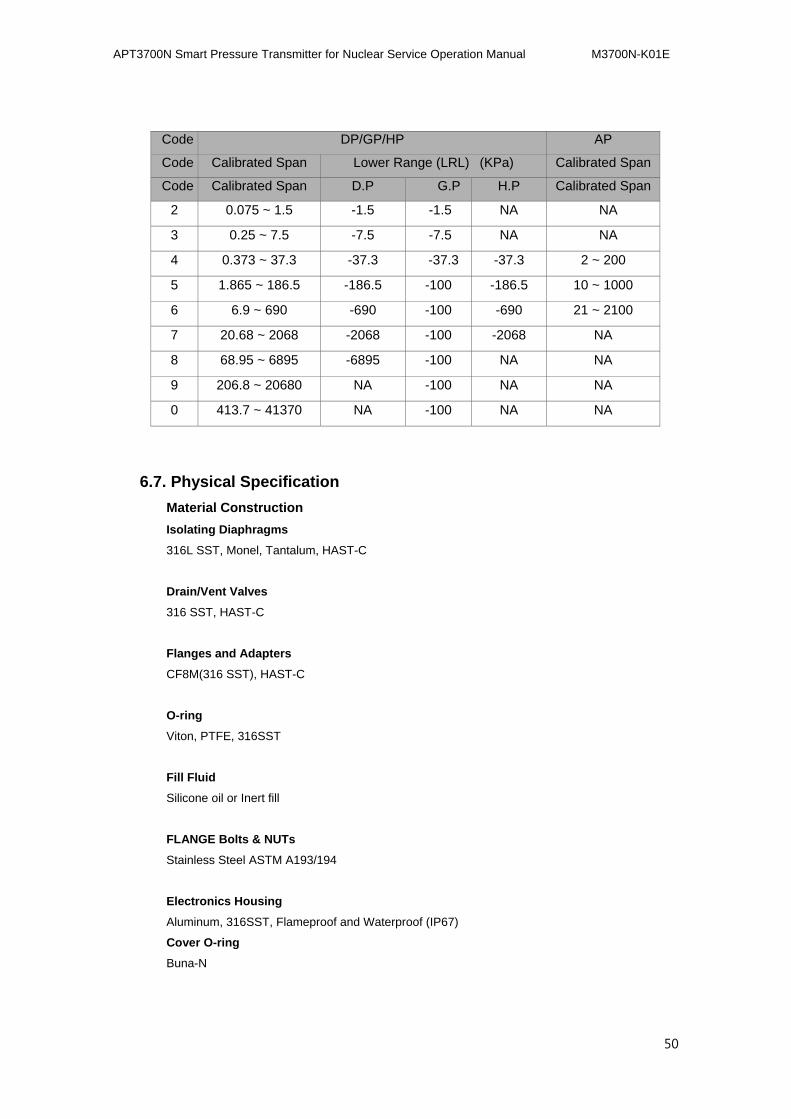
Pressure Range
APT3700N Smart Pressure Transmitter for Nuclear Service Operation Manual M3700N-K01E
50
Code DP/GP/HP AP
Code Calibrated Span Lower Range (LRL) (KPa) Calibrated Span
Code Calibrated Span D.P G.P H.P Calibrated Span
2 0.075 ~ 1.5 -1.5 -1.5 NA NA
3 0.25 ~ 7.5 -7.5 -7.5 NA NA
4 0.373 ~ 37.3 -37.3 -37.3 -37.3 2 ~ 200
5 1.865 ~ 186.5 -186.5 -100 -186.5 10 ~ 1000
6 6.9 ~ 690 -690 -100 -690 21 ~ 2100
7 20.68 ~ 2068 -2068 -100 -2068 NA
8 68.95 ~ 6895 -6895 -100 NA NA
9 206.8 ~ 20680 NA -100 NA NA
0 413.7 ~ 41370 NA -100 NA NA
6.7. Physical Specification
Material Construction
Isolating Diaphragms
316L SST, Monel, Tantalum, HAST-C
Drain/Vent Valves
316 SST, HAST-C
Flanges and Adapters
CF8M(316 SST), HAST-C
O-ring
Viton, PTFE, 316SST
Fill Fluid
Silicone oil or Inert fill
FLANGE Bolts & NUTs
Stainless Steel ASTM A193/194
Electronics Housing
Aluminum, 316SST, Flameproof and Waterproof (IP67)
Cover O-ring
Buna-N
APT3700N Smart Pressure Transmitter for Nuclear Service Operation Manual M3700N-K01E
51
Paint
Epoxy-Polyester or Polyurethane
Mounting Bracket
2-inch Pipe, 304 SST, Painted Carbon Steel with 304 SST U-bolt
Nameplate
304 SST
Electrical connections
1/2-14 NPT conduit with M4 Screw Terminals
Process Connections
1/4-18 NPT on 2.126 inch (54.0 mm) centers on flanges for Standard
1/2-14 NPT on Process Adapter (option)
Weight
5.5 kg (excluding options)
APT3700N Smart Pressure Transmitter for Nuclear Service Operation Manual M3700N-K01E
52
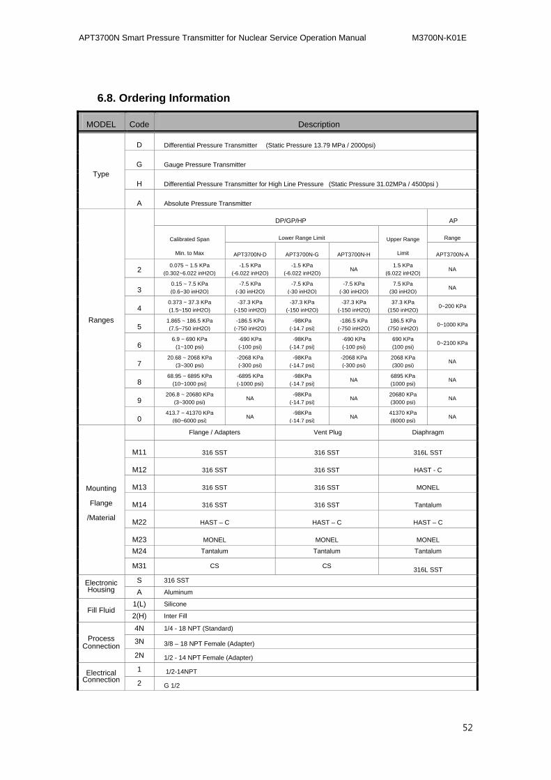
6.8. Ordering Information
MODEL Code Description
Type
D Differential Pressure Transmitter (Static Pressure 13.79 MPa / 2000psi)
G Gauge Pressure Transmitter
H Differential Pressure Transmitter for High Line Pressure (Static Pressure 31.02MPa / 4500psi )
A Absolute Pressure Transmitter
Ranges
DP/GP/HP AP
Calibrated Span
Min. to Max
Lower Range Limit Upper Range
Limit
Range
APT3700N-D APT3700N-G APT3700N-H APT3700N-A
2 0.075 ~ 1.5 KPa (0.302~6.022 inH2O)
-1.5 KPa
(-6.022 inH2O)
-1.5 KPa
(-6.022 inH2O)NA 1.5 KPa
(6.022 inH2O) NA
3 0.15 ~ 7.5 KPa (0.6~30 inH2O)
-7.5 KPa
(-30 inH2O)
-7.5 KPa
(-30 inH2O)
-7.5 KPa
(-30 inH2O)
7.5 KPa (30 inH2O) NA
4 0.373 ~ 37.3 KPa (1.5~150 inH2O)
-37.3 KPa
(-150 inH2O)
-37.3 KPa
(-150 inH2O)
-37.3 KPa
(-150 inH2O)
37.3 KPa (150 inH2O) 0~200 KPa
5 1.865 ~ 186.5 KPa (7.5~750 inH2O)
-186.5 KPa
(-750 inH2O)
-98KPa
(-14.7 psi)
-186.5 KPa
(-750 inH2O)
186.5 KPa (750 inH2O) 0~1000 KPa
6 6.9 ~ 690 KPa
(1~100 psi) -690 KPa
(-100 psi)
-98KPa
(-14.7 psi)
-690 KPa
(-100 psi)
690 KPa (100 psi) 0~2100 KPa
7 20.68 ~ 2068 KPa
(3~300 psi) -2068 KPa
(-300 psi)
-98KPa
(-14.7 psi)
-2068 KPa
(-300 psi)
2068 KPa (300 psi) NA
8 68.95 ~ 6895 KPa
(10~1000 psi) -6895 KPa
(-1000 psi)
-98KPa
(-14.7 psi)NA 6895 KPa
(1000 psi) NA
9 206.8 ~ 20680 KPa
(3~3000 psi) NA -98KPa
(-14.7 psi)NA 20680 KPa
(3000 psi) NA
0 413.7 ~ 41370 KPa
(60~6000 psi) NA -98KPa
(-14.7 psi)NA 41370 KPa
(6000 psi) NA
Mounting
Flange
/Material
Flange / Adapters Vent Plug Diaphragm
M11 316 SST 316 SST 316L SST
M12 316 SST 316 SST HAST - C
M13 316 SST 316 SST MONEL
M14 316 SST 316 SST Tantalum
M22 HAST – C HAST – C HAST – C
M23 MONEL MONEL MONEL M24 Tantalum Tantalum Tantalum
M31 CS CS 316L SST
Electronic Housing
S 316 SST A Aluminum
Fill Fluid 1(L) Silicone 2(H) Inter Fill
Process Connection
4N 1/4 - 18 NPT (Standard)
3N 3/8 – 18 NPT Female (Adapter)
2N 1/2 - 14 NPT Female (Adapter)
Electrical Connection
1 1/2-14NPT 2 G 1/2
APT3700N Smart Pressure Transmitter for Nuclear Service Operation Manual M3700N-K01E
53
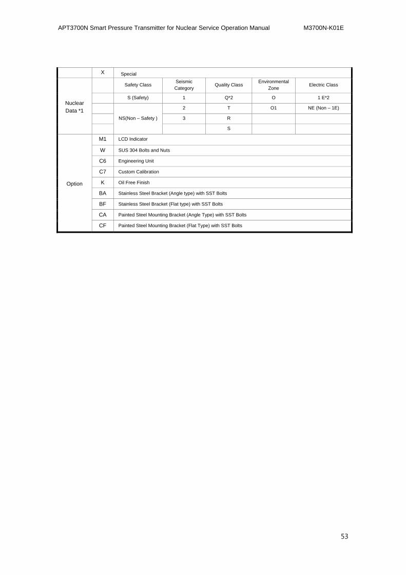
X Special
Nuclear Data *1
Safety Class Seismic
Category Quality Class Environmental Zone Electric Class
S (Safety) 1 Q*2 O 1 E*2
NS(Non – Safety )
2 T O1 NE (Non – 1E)
3 R
S
Option
M1 LCD Indicator
W SUS 304 Bolts and Nuts
C6 Engineering Unit
C7 Custom Calibration
K Oil Free Finish
BA Stainless Steel Bracket (Angle type) with SST Bolts
BF Stainless Steel Bracket (Flat type) with SST Bolts
CA Painted Steel Mounting Bracket (Angle Type) with SST Bolts
CF Painted Steel Mounting Bracket (Flat Type) with SST Bolts