Embed Size (px)
Citation preview

AR No.
IR No.
EIELSON AFB
ALASKA
NOTES:
Administrative Record
Cover Sheet

THE UNITED STATES AIR FORCE INSTALLATION RESTORATION PROGRAM
FINAL ADDENDUM NO. 1 TO THE
FINAL VERSION 3 QUALITY ASSURANCE PROJECT PLAN
SUPPLEMENTAL REMEDIAL INVESTIGATION SOURCE AREAS WP45/SS57
EIELSON AIR FORCE BASE, ALASKA
Prepared for: Air Force Civil Engineer Center
Contract No. FA8903-08-D-8791-0026
January 2013

This page intentionally left blank.

FINAL ADDENDUM NO. 1 TO THE
FINAL VERSION 3 QUALITY ASSURANCE PROJECT PLAN
SUPPLEMENTAL REMEDIAL INVESTIGATION SOURCE AREAS WP45/SS57
EIELSON AIR FORCE BASE, ALASKA
Prepared for:
Air Force Civil Engineer Center Contract No. FA8903-08-D-8791-0026
Prepared by:
EA Engineering, Science, and Technology, Inc. 3544 International Street Fairbanks, Alaska 99701
January 2013

This page intentionally left blank.
Table of Contents Title: QAPP Addendum No. 1 for SRI for Source Areas WP45/SS57 Revision Number: 0 Revision Date: January 2013 Contract No. FA8903-08-D-8791-0026
EA Engineering, Science, and Technology, Inc. Page TOC-1
TABLE OF CONTENTS
SECTION PAGE List of Appendices.…………………………………………………………………. ............. .TOC-1 List of Figures………...……………………………………………………………… ....... …..TOC-2 List of Tables………...……………………………………………………………… ........ …..TOC-2 1.0 INTRODUCTION ....................................................................................................... 1 2.0 BACKGROUND ......................................................................................................... 1 3.0 PREVIOUS SAMPLING ............................................................................................ 2 4.0 SAMPLING RATIONALE, SAMPLING MEDIA, AND ANALYTICAL SUITES ............. 2 5.0 DECISIONS............................................................................................................... 3 6.0 SCHEDULE ............................................................................................................... 3 7.0 REFERENCES .......................................................................................................... 3
APPENDICES Appendix A Photographs of Dry Well (Excerpt from Final Work Plan Phase II Class V
Underground Injection Control Implementation and Close Class V UIC Structures [USAF 2011])
Appendix B Response To Comments to the Draft Addendum No. 1 for SRI for Source Areas WP45/SS57
FIGURES
Figure 1 Proposed Sampling Locations for Photo Lab Investigation
TABLES
Table 1 Proposed Field Sampling for Investigation of a Potential Release from the Photo Lab, Source Area WP45, Eielson Air Force Base, Alaska

Table of Contents Title: QAPP Addendum No. 1 for SRI for Source Areas WP45/SS57 Revision Number: 0 Revision Date: January 2013 Contract No. FA8903-08-D-8791-0026
EA Engineering, Science, and Technology, Inc. Page TOC-2
This page intentionally left blank.

Title: QAPP Addendum No. 1 for SRI for Source Areas WP45/SS57 Revision Number: 0 Revision Date: January 2013 Contract No. FA8903-08-D-8791-0026
EA Engineering, Science, and Technology, Inc. Page 1
1.0 INTRODUCTION The Air Force Civil Engineer Center (AFCEC) has contracted EA Engineering, Science, and Technology, Inc. (EA) to perform a supplemental remedial investigation (SRI) at Source Areas WP45 (Photo Lab) and SS57 (Fire Station Parking Lot) (hereinafter identified as WP45/SS57), within Operable Unit (OU) 3 at Eielson Air Force Base (AFB), Alaska. A Quality Assurance Project Plan (QAPP) was prepared for this investigation and the Final Version 3 of this QAPP (U.S. Air Force [USAF] 2012a) was approved by the U.S. Environmental Protection Agency (USEPA) and Alaska Department of Environmental Conservation (ADEC) on 7 May 2012. This addendum has been prepared to address additional investigation activities to be performed in association with releases from the Photo Lab, WP45, as per stakeholders’ decision at the 23 November 2011 meeting. A stakeholders scoping meeting took place at the ADEC office in Fairbanks, Alaska, on 30 August 2012. Participants, either present in the room or via telephone, included the following:
• David Beistel – Eielson AFB • Joann Socash – Booz Allen Hamilton/AFCEC • Kimberly DeRuyter –ADEC • Eric Breitenberger – ADEC • Aaron Lambert – U.S. Environmental Protection Agency (EPA) • Kelly Findlay – EA • Cristina Radu – EA • Jay Snyder – EA • Kyle Waldron – EA • Mark Wilkinson – EA
During this scoping meeting, the stakeholders agreed upon the scope of work for this additional investigation. Because this QAPP Addendum No. 1 expands from the list of contaminants of concern from those addressed in the WP45/SS57 Final Version 3 Revision 1 QAPP to include two metals (silver and chromium), the stakeholders also agreed during the 23 November 2011 meeting that the requirements for the analytical laboratory will be those specified for these analytes in the Final Version 2 Revision 1 Installation-Wide Generic QAPP (USAF 2012b). 2.0 BACKGROUND Source Area WP45 is located around Building 1183 where a small photography laboratory was formerly operated. A dry well located adjacent to Building 1183 has received photographic waste from the shop. Photographs of this dry well, as shown in the Phase II Class V Underground Injection Control (UIC) Implementation Report (USAF 2011), are included in Appendix A. Appendix B contains the Response to Comments received in the letter with the conditional approval of the Draft QAPP Addendum No. 1 for SRI for Source Areas WP45/SS57 (ADEC/EPA 2012).

Title: QAPP Addendum No. 1 for SRI for Source Areas WP45/SS57 Revision Number: 0 Revision Date: January 2013 Contract No. FA8903-08-D-8791-0026
EA Engineering, Science, and Technology, Inc. Page 2
Building 1183 includes a parking garage, washing facility, and offices. The dry well consists of a 4.5-foot-diameter steel casing located at the northwest side of the building. The bottom of the well is 8.3 feet (ft) below the top of casing. The dry well has not been removed because its removal could compromise the structure of the building. However, the drain leading to the well was plugged with cement in 1993 (USAF 2009). 3.0 PREVIOUS SAMPLING The dry well at Building 1183 was identified during an installation-wide Class V UIC inventory (USAF 2009). During a pre-closure investigation in May 2010, water was observed in the bottom of the well. In May and July 2011, water was not observed in the well but at that time samples of solid media from the bottom of the well were collected for pre-closure characterization. These samples were analyzed for gasoline range organics (GRO), diesel range organics (DRO), volatile organic compounds (VOC), semivolatile organic compounds (SVOC), metals, and pesticides. Pre-closure sample results were presented in the Final Work Plan Phase II Class V UIC Implementation and Close Class V UIC Structures (USAF 2011). DRO and metals were the only COCs detected at concentrations above the laboratory reporting limits. Although the sampled media should not be considered soil, the results were compared to ADEC Method Two Soil Cleanup Levels (Alaska Administrative Code 2012) as a reference. DRO, arsenic, chromium, and silver were detected at concentrations exceeding the soil cleanup levels for the migration-to-groundwater pathway. Results of Toxicity Characteristic Leaching Procedure (TCLP) metals analysis indicated that the material in the dry well is not a Resource Conservation and Recovery Act (RCRA) hazardous waste. 4.0 SAMPLING RATIONALE, MEDIA, AND ANALYTICAL SUITES The sampling program associated with the Photo Lab is based on the agreement reached with the stakeholders during the scoping meeting on 30 August 2012. Table 1 presents the matrices to be sampled, samples to be collected and rationale for collection, sampling depths, analytical suites, sample IDs, sampling tools, standard operating procedures (SOPs) to be employed, and QC samples applicable for each medium. Sampling locations are provided in Figure 1. Further details of the soil and groundwater sampling are provided below. Soil Characterization:
• One soil boring (SB28) will be completed adjacent to the dry well, near the pipe penetration point. Of note, access may be partially limited due to the presence of an overhead power line at the dry well. Although field conditions at SB28 as of 11 January
Title: QAPP Addendum No. 1 for SRI for Source Areas WP45/SS57 Revision Number: 0 Revision Date: January 2013 Contract No. FA8903-08-D-8791-0026
EA Engineering, Science, and Technology, Inc. Page 3
2013 do not indicate there may be a problem with the boring installation, the regulators will be contacted in case the boring needs to be moved.
• Two soil samples will be collected from this boring, as follows:
− 1) One sample will be collected immediately below the pipe penetration depth (as the most likely interval to be contaminated by possible leakage from the dry well at the pipe entry point)
− 2) One sample will be collected at the groundwater interface.
• Analytical suite: Soil samples will be analyzed for silver and chromium using EPA
Method 6020.
Groundwater Characterization:
• One existing monitoring well (45M01), located northwest of the dry well will be sampled. This well was not included in the 2011 SRI sampling event.
• One new monitoring well will be installed downgradient from the dry well and sampled. The stakeholders may decide to locate one of the groundwater monitoring wells proposed for installation as part of the 2012 SRI activities closer to the dry well.
• Water table monitoring well(s) will be constructed using regulator approved methods; well development and sample collection will be performed according to approved procedures.
• Analytical suite: Due to the locations of these wells and former detections of organic compounds, the groundwater samples will be analyzed for silver using EPA Method 6020 and the organic compounds of concern identified in the WP45/SS57 QAPP including GRO using Method AK101, DRO using Method AK102, residual range organics (RRO using Method AK103, VOCs using EPA Method 8260B, ethylene dibromide (EDB) using EPA Method 8011, and PAHs using EPA Method 8270C using selected ion monitoring mode. In addition, groundwater will be field analyzed for temperature, pH, specific conductivity, oxidation-reduction potential, dissolved oxygen, and turbidity.
Table 1 includes the environmental and quality control (QC) samples applicable to this additional soil and groundwater characterization. 5.0 DECISIONS
Soil and groundwater data will be evaluated based on the same “if/then” statements described in Worksheet #10 of the QAPP for the SRI at WP45/SS57 (USAF 2012a). Stakeholders will determine the path forward based on the sample results.

Title: QAPP Addendum No. 1 for SRI for Source Areas WP45/SS57 Revision Number: 0 Revision Date: January 2013 Contract No. FA8903-08-D-8791-0026
EA Engineering, Science, and Technology, Inc. Page 4
6.0 SCHEDULE
Field implementation for the activities comprised in this QAPP addendum is projected for Fall 2012. 7.0 REFERENCES
Alaska Administrative Code (AAC). 2012. Oil and Other Hazardous Substances Pollution Control, Title 18 Chapter 75. April.
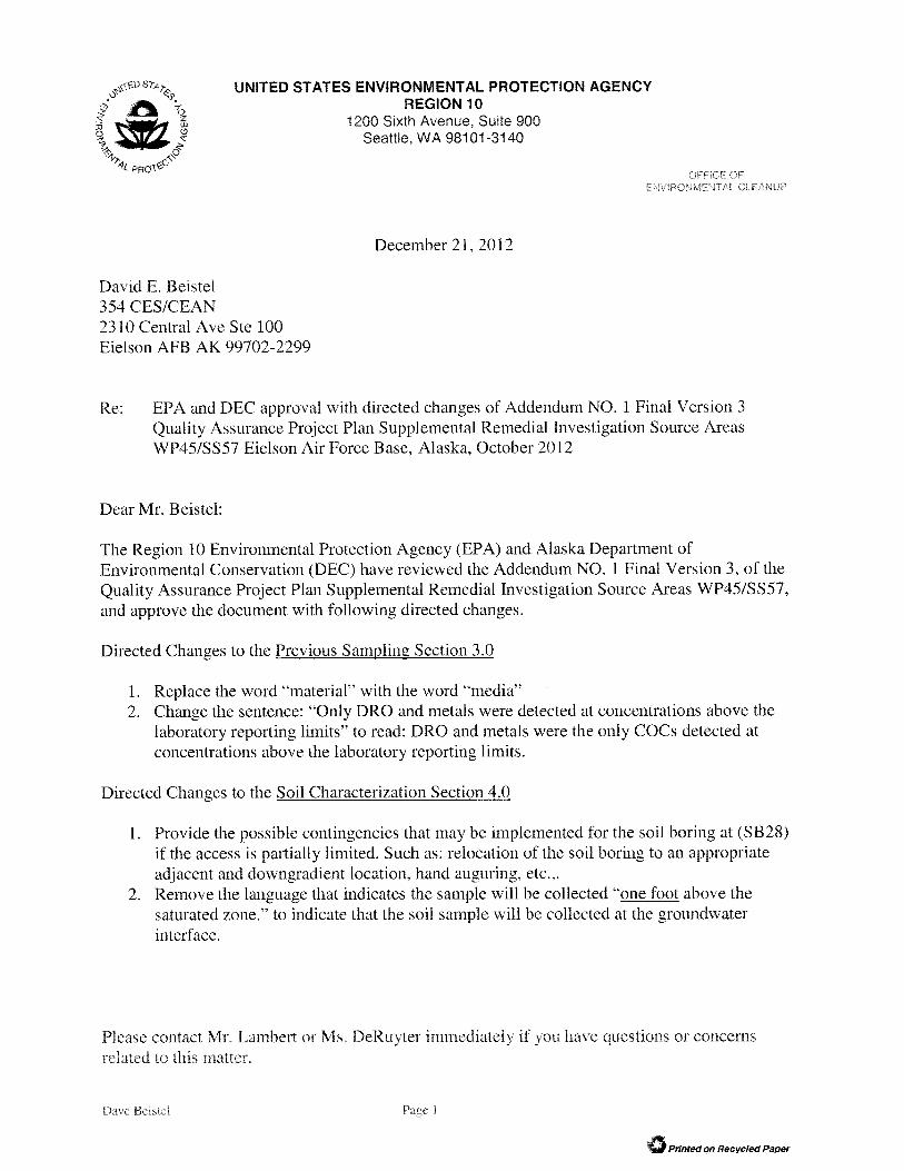
Alaska Department of Environmental Conservation/U.S. Environmental Protection Agency,
Region 10. 2012. Letter. EPA/DEC approval with directed changes of Addendum No. 1 Final Version 3 Quality Assurance Project Plan Supplemental Remedial Investigation Source Areas WP45/SS57 Eielson Air Force Base, Alaska, October 2012. 21 December 2012.
U.S. Air Force (USAF). 2009. Final Report of Findings, Identification and Closure of Class V
Underground Injections Control Structures. November USAF. 2011. Final Work Plan. Phase II Class V Underground Injection Control (UIC)
Implementation and Close Class V UIC Structures, Eielson Air Force Base, Alaska. July.
USAF, 2012a. Quality Assurance Project Plan for the Supplemental Remedial Investigation at Source Areas WP45/SS57. Final Version 3. February.
USAF, 2012b. Installation-Wide Generic Quality Assurance Project Plan for Eielson Air Force Base. Final Version 2, Revision 1. October.
Figures Title: QAPP Addendum No. 1 for SRI for Source Areas WP45/SS57 Revision Number: 0 Revision Date: January 2013 Contract No. FA8903-08-D-8791-0026
EA Engineering, Science, and Technology, Inc.
FIGURES

Figures Title: QAPP Addendum No. 1 for SRI for Source Areas WP45/SS57 Revision Number: 0 Revision Date: January 2013 Contract No. FA8903-08-D-8791-0026
EA Engineering, Science, and Technology, Inc.
This page intentionally left blank.

DDDD
D
DDDDDDDDD
DD
D
D
DD
DD
DD
D
DD
D
D D D D D D D D D DD
DD
D
D D D D D
D
DD
DD
D
D D D
D
@A
@A
@A
@A
@A
@A
@A
@A
@A
@A
@A
@A
@A
@A
@A@A
@A@A@A
@A@A@A
@A
@A
@A
@A
@A
@A
@A
@A
@A@A
@A
@A
@A
$1"
(
#
45MW37SB28
45M01
45MW28
45MW2745MW25
45MW2245MW20
45MW03I
45MW2645MW24
45MW19
45MW1845MW1745MW16
45MW23
1183
1168
1187
1186
Figure 1Proposed Sampling Locations for Photo Lab
InvestigationAFCEE Contract No. FA8903-08-D-8791-0026 EA Project No. 1456026
$
0 40 8020
Feet
Legend@A Existing Monitoring Well
$1 Abandoned Dry Well# Emergency Fire Well C
(Proposed Water Table Well(screen interval 8-28 feet bgs)
" Proposed Soil Boring
Path:
\\FAI
RBAN
KS\pr
ojects
\1456
026 E
ielso
n 201
1\GIS
\4557
\Silve
r Inve
stiga
tion\S
ilver.m
xd
Groundwater Flow Direction(Monitoring wells gauged 8 August 2011)
Note: 1. Total Silver detected at 0.0296 mg/L in groundwater sample from well 45M01 in 1989 (USAF. 1989. Source Area 45 Photo Laboratory).2. Proposed monitoring well 45MW37 will be installed as agreed by stakeholders during the Triad meetings and as proposed in the Technical Memorandum (USAF. 2012. Technical Memorandum for Source Areas WP45/SS57 2011 Investigation).
Addendum No. 1Supplemental Remedial Investigation
Source Areas WP45/SS57Eielson Air Force Base

This page is intentionally left blank.

Tables Title: QAPP Addendum No. 1 for SRI for Source Areas WP45/SS57 Revision Number: 0 Revision Date: January 2013 Contract No. FA8903-08-D-8791-0026
EA Engineering, Science, and Technology, Inc.
TABLES

Tables Title: QAPP Addendum No. 1 for SRI for Source Areas WP45/SS57 Revision Number: 0 Revision Date: January 2013 Contract No. FA8903-08-D-8791-0026
EA Engineering, Science, and Technology, Inc.
This page intentionally left blank.

TABLE 1 PROPOSED FIELD SAMPLING FOR INVESTIGATIONOF A POTENTIAL RELEASE FROM THE PHOTO LAB, SOURCE AREA WP45
EIELSON AIR FORCE BASE, ALASKA
Page 1 of 2
Sample Location Total Depth (ft bgs)
Point ID (Location ID)
Sample ID (the last digits for soil samples identify
the bottom of the sampling interval)
Matrix Sample Type
Sampling Method/Tool
Sampling/Measurement
Frequency
Sample Depth (ft bgs unless
otherwise indicated)
Expected Concentration
Level
GR
O -
AK
1011
DR
O/R
RO
1 - A
K10
2/10
3
VOC
s - S
W82
60B
E DB
- SW
8011
2
PAH
s - S
W82
70 S
IM
Silv
er a
nd C
hrom
ium
- SW
6020
pH
Con
duct
ivity
Tem
pera
ture
DO
OR
P
Turb
idity
Sampling Rationale EA Field SOP
Soil Borings for Characterizing a Release of Silver to Soil from the Dry Well
SB28-7.5 (bottom of sample depending on the
pipe penetration point)
estimated 6.5 - 7.5 0 0 0 0 0 1 NA NA NA NA NA NA
SB28-bottom depth
One sample will be collected at
the groundwater interface
0 0 0 0 0 1 NA NA NA NA NA NA
0 0 0 0 0 2Field QC Samples
Field Duplicates (10 percent rounded up) NA
Same as the sample it duplicates
Blind Sample - To be assigned a fictitious
sample ID Soil Direct Push Sampler 10% rounded up
Same as the sample it duplicates
Low 0 0 0 0 0 1 NA NA NA NA NA NA Field QC - indicative of precisionSame as for
sample duplicated
Equipment Blanks (assume 1 days of sampling) NA NA 4557-EB-01 Water Grab One per day NA Low 1 1 1 0 1 1 NA NA NA NA NA NA Field QC - indicative of accuracy
SOP-001SOP-002SOP-004
MS/MSDs (5 percent rounded up) NA Various Same as the sample
associated with it Soil Direct Push Sampler 5% rounded up
Same as the sample with which it is associated
Low EV EV EV EV EV EV NA NA NA NA NA NALaboratory QC - indicative of precision and
accuracy. Same as primary sample, only extra volume collected.
Same as for associated
sample
0 0 0 0 0 10 0 0 0 0 3
Total Aqueous QC Samples Associated with Soil Characterization 1 1 1 0 1 1Groundwater Investigation Associated with the Dry Well Release
New well: downgradient from dry well - may consider with the location of one of the proposed wells
18.5(estimated
based on 9 ft depth to
groundwater)
45MW37 45MW37 Low 1 1 1 1 1 1 Yes Yes Yes Yes Yes Yes Evaluate groundwater quality downgradient of dry well.
Existing well: northwest of dry well 16 45M01 45M01 Low 1 1 1 1 1 1 Yes Yes Yes Yes Yes Yes Evaluate groundwater quality adjacent to the dry
well.
2 2 2 2 2 2
Total Soil Samples Associated with Soil Characterization
SOP-001SOP-002SOP-004SOP-011SOP-025SOP-047
Sample location was chosen to capture the area with the highest likelihood of soil contamination on the side of the dry well where the concrete culvert
is penetrated by the metal pipe.
The first interval to be sampled is immediately below the point where the metal pipe penetrates the dry well. Estimated penetration depth is 6.5 ft
bgs.
The second interval to be sampled is above the capillary fringe. The sampling depth will depend on
the depth to groundwater. For purposes of well design, the top of the capillary fringe is assumed to
be 1 ft above the highest seasonal water table elevation.
Low flow peristaltic pump with inertial foot
valve Grab
Total Soil Field QC Samples Associated with the Soil Characterization
Total Environmental Soil Samples
QC
Water
Total Environmental Aqueous Samples Associated with Groundwater Investigation
Field Analyses
As close as possible to the well culvert on the side where the
metal pipe enters the well
Approximately 11 SB28 Soil Grab Direct Push Sampler Once Low
Laboratory Analyses/Procedures
SOP-001SOP-002SOP-004 SOP-010SOP-011 SOP-013 SOP-019 SOP-036 SOP-043 SOP-048
Middle of the submerged
screened zoneOnce
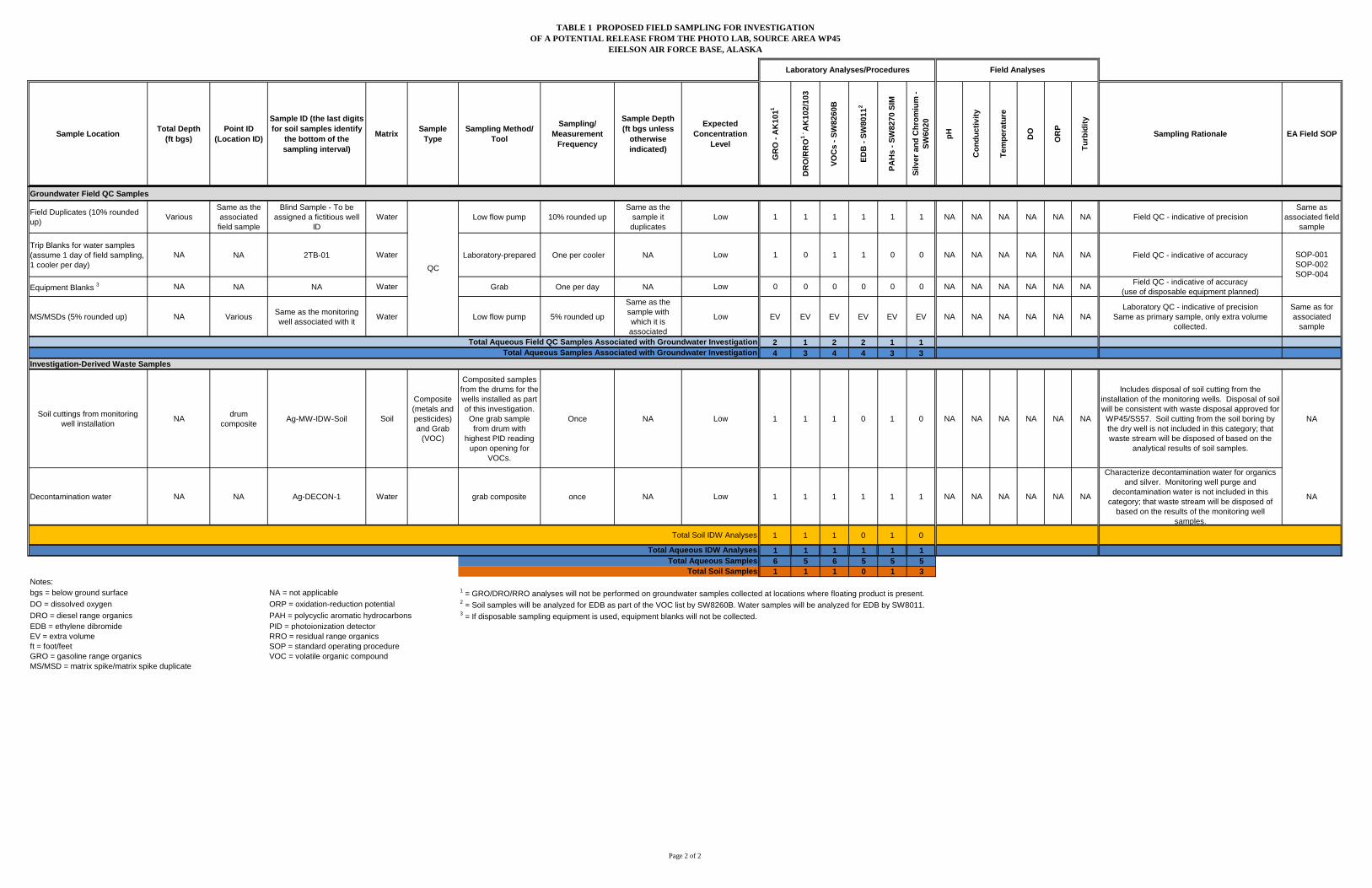
TABLE 1 PROPOSED FIELD SAMPLING FOR INVESTIGATIONOF A POTENTIAL RELEASE FROM THE PHOTO LAB, SOURCE AREA WP45
EIELSON AIR FORCE BASE, ALASKA
Page 2 of 2
Sample Location Total Depth (ft bgs)
Point ID (Location ID)
Sample ID (the last digits for soil samples identify
the bottom of the sampling interval)
Matrix Sample Type
Sampling Method/Tool
Sampling/Measurement
Frequency
Sample Depth (ft bgs unless
otherwise indicated)
Expected Concentration
Level
GR
O -
AK
1011
DR
O/R
RO
1 - A
K10
2/10
3
VOC
s - S
W82
60B
E DB
- SW
8011
2
PAH
s - S
W82
70 S
IM
Silv
er a
nd C
hrom
ium
- SW
6020
pH
Con
duct
ivity
Tem
pera
ture
DO
OR
P
Turb
idity
Sampling Rationale EA Field SOP
Field AnalysesLaboratory Analyses/Procedures
Groundwater Field QC Samples
Field Duplicates (10% rounded up) Various
Same as the associated field sample
Blind Sample - To be assigned a fictitious well
ID Water Low flow pump 10% rounded up
Same as the sample it duplicates
Low 1 1 1 1 1 1 NA NA NA NA NA NA Field QC - indicative of precisionSame as
associated field sample
Trip Blanks for water samples (assume 1 day of field sampling, 1 cooler per day)
NA NA 2TB-01 Water Laboratory-prepared One per cooler NA Low 1 0 1 1 0 0 NA NA NA NA NA NA Field QC - indicative of accuracy
Equipment Blanks 3 NA NA NA Water Grab One per day NA Low 0 0 0 0 0 0 NA NA NA NA NA NA Field QC - indicative of accuracy (use of disposable equipment planned)
MS/MSDs (5% rounded up) NA Various Same as the monitoring well associated with it Water Low flow pump 5% rounded up
Same as the sample with which it is associated
Low EV EV EV EV EV EV NA NA NA NA NA NALaboratory QC - indicative of precision
Same as primary sample, only extra volume collected.
Same as for associated
sample
2 1 2 2 1 14 3 4 4 3 3
Investigation-Derived Waste Samples
Soil cuttings from monitoring well installation NA drum
composite Ag-MW-IDW-Soil Soil
Composite (metals and pesticides) and Grab
(VOC)
Composited samples from the drums for the wells installed as part of this investigation.
One grab sample from drum with
highest PID reading upon opening for
VOCs.
Once NA Low 1 1 1 0 1 0 NA NA NA NA NA NA
Includes disposal of soil cutting from the installation of the monitoring wells. Disposal of soil will be consistent with waste disposal approved for
WP45/SS57. Soil cutting from the soil boring by the dry well is not included in this category; that waste stream will be disposed of based on the
analytical results of soil samples.
NA
Decontamination water NA NA Ag-DECON-1 Water grab composite once NA Low 1 1 1 1 1 1 NA NA NA NA NA NA
Characterize decontamination water for organics and silver. Monitoring well purge and
decontamination water is not included in this category; that waste stream will be disposed of
based on the results of the monitoring well samples.
NA
Total Soil IDW Analyses 1 1 1 0 1 0
1 1 1 1 1 16 5 6 5 5 51 1 1 0 1 3
Notes:bgs = below ground surface NA = not applicable 1 = GRO/DRO/RRO analyses will not be performed on groundwater samples collected at locations where floating product is present.DO = dissolved oxygen ORP = oxidation-reduction potential 2 = Soil samples will be analyzed for EDB as part of the VOC list by SW8260B. Water samples will be analyzed for EDB by SW8011.DRO = diesel range organics PAH = polycyclic aromatic hydrocarbons 3 = If disposable sampling equipment is used, equipment blanks will not be collected.EDB = ethylene dibromide PID = photoionization detectorEV = extra volume RRO = residual range organicsft = foot/feet SOP = standard operating procedureGRO = gasoline range organics VOC = volatile organic compoundMS/MSD = matrix spike/matrix spike duplicate
Total Aqueous SamplesTotal Soil Samples
Total Aqueous IDW Analyses
SOP-001SOP-002SOP-004
Total Aqueous Samples Associated with Groundwater Investigation
QC
Total Aqueous Field QC Samples Associated with Groundwater Investigation

TABLE 1 PROPOSED FIELD SAMPLING FOR INVESTIGATIONOF A POTENTIAL RELEASE FROM THE PHOTO LAB, SOURCE AREA WP45
EIELSON AIR FORCE BASE, ALASKA
Page 2 of 2
Sample Location Total Depth (ft bgs)
Point ID (Location ID)
Sample ID (the last digits for soil samples identify
the bottom of the sampling interval)
Matrix Sample Type
Sampling Method/Tool
Sampling/Measurement
Frequency
Sample Depth (ft bgs unless
otherwise indicated)
Expected Concentration
Level
GR
O -
AK
1011
DR
O/R
RO
1 - A
K10
2/10
3
VOC
s - S
W82
60B
EDB
- SW
8011
2
PAH
s - S
W82
70 S
IM
Silv
er a
nd C
hrom
ium
- SW
6020
pH
Con
duct
ivity
Tem
pera
ture
DO
OR
P
Turb
idity
Sampling Rationale EA Field SOP
Field AnalysesLaboratory Analyses/Procedures
Groundwater Field QC Samples
Field Duplicates (10% rounded up) Various
Same as the associated field sample
Blind Sample - To be assigned a fictitious well
ID Water Low flow pump 10% rounded up
Same as the sample it duplicates
Low 1 1 1 1 1 1 NA NA NA NA NA NA Field QC - indicative of precisionSame as
associated field sample
Trip Blanks for water samples (assume 1 day of field sampling, 1 cooler per day)
NA NA 2TB-01 Water Laboratory-prepared One per cooler NA Low 1 0 1 1 0 0 NA NA NA NA NA NA Field QC - indicative of accuracy
Equipment Blanks 3 NA NA NA Water Grab One per day NA Low 0 0 0 0 0 0 NA NA NA NA NA NA Field QC - indicative of accuracy (use of disposable equipment planned)
MS/MSDs (5% rounded up) NA Various Same as the monitoring well associated with it Water Low flow pump 5% rounded up
Same as the sample with which it is associated
Low EV EV EV EV EV EV NA NA NA NA NA NALaboratory QC - indicative of precision
Same as primary sample, only extra volume collected.
Same as for associated
sample
2 1 2 2 1 14 3 4 4 3 3
Investigation-Derived Waste Samples
Soil cuttings from monitoring well installation NA drum
composite Ag-MW-IDW-Soil Soil
Composite (metals and pesticides) and Grab
(VOC)
Composited samples from the drums for the wells installed as part of this investigation.
One grab sample from drum with
highest PID reading upon opening for
VOCs.
Once NA Low 1 1 1 0 1 0 NA NA NA NA NA NA
Includes disposal of soil cutting from the installation of the monitoring wells. Disposal of soil will be consistent with waste disposal approved for
WP45/SS57. Soil cutting from the soil boring by the dry well is not included in this category; that waste stream will be disposed of based on the
analytical results of soil samples.
NA
Decontamination water NA NA Ag-DECON-1 Water grab composite once NA Low 1 1 1 1 1 1 NA NA NA NA NA NA
Characterize decontamination water for organics and silver. Monitoring well purge and
decontamination water is not included in this category; that waste stream will be disposed of
based on the results of the monitoring well samples.
NA
Total Soil IDW Analyses 1 1 1 0 1 0
1 1 1 1 1 16 5 6 5 5 51 1 1 0 1 3
Notes:bgs = below ground surface NA = not applicable 1 = GRO/DRO/RRO analyses will not be performed on groundwater samples collected at locations where floating product is present.DO = dissolved oxygen ORP = oxidation-reduction potential 2 = Soil samples will be analyzed for EDB as part of the VOC list by SW8260B. Water samples will be analyzed for EDB by SW8011.DRO = diesel range organics PAH = polycyclic aromatic hydrocarbons 3 = If disposable sampling equipment is used, equipment blanks will not be collected.EDB = ethylene dibromide PID = photoionization detectorEV = extra volume RRO = residual range organicsft = foot/feet SOP = standard operating procedureGRO = gasoline range organics VOC = volatile organic compoundMS/MSD = matrix spike/matrix spike duplicate
QC
Total Aqueous Field QC Samples Associated with Groundwater Investigation
Total Aqueous SamplesTotal Soil Samples
Total Aqueous IDW Analyses
SOP-001SOP-002SOP-004
Total Aqueous Samples Associated with Groundwater Investigation

This page is intentionally left blank.

Appendices Title: QAPP Addendum No. 1 for SRI for Source Areas WP45/SS57 Revision Number: 0 Revision Date: January 2013 Contract No. FA8903-08-D-8791-0026
EA Engineering, Science, and Technology, Inc.
APPENDICES

Appendices Title: QAPP Addendum No. 1 for SRI for Source Areas WP45/SS57 Revision Number: 0 Revision Date: January 2013 Contract No. FA8903-08-D-8791-0026
EA Engineering, Science, and Technology, Inc.
This page intentionally left blank.

Appendix A Title: QAPP Addendum No. 1 for SRI for Source Areas WP45/SS57 Revision Number: 0 Revision Date: January 2013 Contract No. FA8903-08-D-8791-0026
EA Engineering, Science, and Technology, Inc.
APPENDIX A
Photographs of Dry Well (Excerpt from Final Work Plan Phase II Class V Underground Injection Control Implementation and Close Class V UIC Structures [USAF 2011])
Appendix A Title: QAPP Addendum No. 1 for SRI for Source Areas WP45/SS57 Revision Number: 0 Revision Date: January 2013 Contract No. FA8903-08-D-8791-0026
EA Engineering, Science, and Technology, Inc.
This page intentionally left blank.

SHANNON & WILSON, INC.
APPENDIX C PRE-CLOSURE SITE PHOTOGRAPHS
Phase II Class V Underground Injection Control (UIC) Implementation and Close Class V UIC Structures Page 1 Eielson Air Force Base, Alaska 31-1-11512-001
Photo 1: UIC Building 1183, steel, 4.5 feet in diameter, 8.3 feet deep.
Photo 2: UIC Building 1183, left of safety cone. Close proximity to Building 1183 and overhead power pole.
Photo 3: Seismometer installed on Building 1183 UIC.

This page intentionally left blank.

Appendix B Title: QAPP Addendum No. 1 for SRI for Source Areas WP45/SS57 Revision Number: 0 Revision Date: January 2013 Contract No. FA8903-08-D-8791-0026
EA Engineering, Science, and Technology, Inc.
APPENDIX B
Response To Comments to the Draft Addendum No. 1 for SRI for Source Areas WP45/SS57

Appendix B Title: QAPP Addendum No. 1 for SRI for Source Areas WP45/SS57 Revision Number: 0 Revision Date: January 2013 Contract No. FA8903-08-D-8791-0026
EA Engineering, Science, and Technology, Inc.
This page intentionally left blank.

Page 1 of 1 January 11, 2013
Alaska Department of Environmental Conservation and United States Environmental Protection Agency Comments on:
Draft Addendum No. 1 to the Final Version 3 Quality Assurance Project Plan Supplemental Remedial Investigation, Source Areas WP45/SS57, Eielson Air Force Base, Alaska, June 2012
Cmt. No. Comment/Recommendation Evaluation of
Response Response and Location of
Change
1.
Directive Changes to the Previous Sampling Section 3.0: 1. Replace the word "material" with the word "media".
Comment has been addressed.
Text was changed to recommended language. See page 2 under Previous Sampling Section 3.0.
2.
Directive Changes to the Previous Sampling Section 3.0: 2. Change the sentence: "Only DRO and metals were detected at
concentrations above the laboratory reporting limits" to read: DRO and metals were the only COCs detected at concentrations above the laboratory reporting limits.
Comment has been addressed.
Text was changed to recommended language. See page 2 under Previous Sampling Section 3.0.
3.
Directive Changes to the Soil Characterization Section 4.0: 1. Provide the possible contingencies that may be implemented for the soil
boring at (SB28) if the access is partially limited. Such as: relocation of the soil boring to an appropriate adjacent and downgradient location, hand auguring, etc.
Comment has been addressed.
Text was added to address possible contingencies. See page 2-3 under Soil Characterization Section 4.0.
4.
Directive Changes to the Soil Characterization Section 4.0: 2. Remove the language that indicates the sample will be collected ··one foot
above the saturated zone.'' to indicate that the soil sample will be collected at the groundwater interface.
Comment has been addressed.
Text was changed to recommended language. See page 3 under Soil Characterization Section 4.0. See Table 1, page 1 of 2 for additional change to text.

This page intentionally left blank.
THE UNITED STATES AIR FORCE INSTALLATION RESTORATION PROGRAM
FINAL ADDENDUM NO. 1 TO THE
FINAL VERSION 3 QUALITY ASSURANCE PROJECT PLAN
SUPPLEMENTAL REMEDIAL INVESTIGATION SOURCE AREAS WP45/SS57
EIELSON AIR FORCE BASE, ALASKA
Prepared for: Air Force Civil Engineer Center
Contract No. FA8903-08-D-8791-0026
January 2013
Deleted: October 2012
FINAL ADDENDUM NO. 1 TO THE
FINAL VERSION 3 QUALITY ASSURANCE PROJECT PLAN
SUPPLEMENTAL REMEDIAL INVESTIGATION SOURCE AREAS WP45/SS57
EIELSON AIR FORCE BASE, ALASKA
Prepared for:
Air Force Civil Engineer Center Contract No. FA8903-08-D-8791-0026
Prepared by:
EA Engineering, Science, and Technology, Inc. 3544 International Street Fairbanks, Alaska 99701
January 2013
Deleted: October 2012

Table of Contents Title: QAPP Addendum No. 1 for SRI for Source Areas WP45/SS57 Revision Number: 0 Revision Date: January 2013 Contract No. FA8903-08-D-8791-0026
EA Engineering, Science, and Technology, Inc. Page TOC-1
Deleted: October 2012
TABLE OF CONTENTS
SECTION PAGE List of Appendices.…………………………………………………………………. ............. .TOC-1 List of Figures………...……………………………………………………………… ....... …..TOC-2 List of Tables………...……………………………………………………………… ........ …..TOC-2 1.0 INTRODUCTION ....................................................................................................... 1 2.0 BACKGROUND ......................................................................................................... 1 3.0 PREVIOUS SAMPLING ............................................................................................ 2 4.0 SAMPLING RATIONALE, SAMPLING MEDIA, AND ANALYTICAL SUITES ............. 2 1.0 DECISIONS............................................................................................................... 3 1.0 SCHEDULE ............................................................................................................... 3 1.0 REFERENCES .......................................................................................................... 3
APPENDICES Appendix A Photographs of Dry Well (Excerpt from Final Work Plan Phase II Class V
Underground Injection Control Implementation and Close Class V UIC Structures [USAF 2011])
Appendix B Response To Comments to the Draft Addendum No. 1 for SRI for Source Areas WP45/SS57
FIGURES
Figure 1 Proposed Sampling Locations for Photo Lab Investigation
TABLES
Table 1 Proposed Field Sampling for Investigation of a Potential Release from the Photo Lab, Source Area WP45, Eielson Air Force Base, Alaska

Table of Contents Title: QAPP Addendum No. 1 for SRI for Source Areas WP45/SS57 Revision Number: 0 Revision Date: January 2013 Contract No. FA8903-08-D-8791-0026
EA Engineering, Science, and Technology, Inc. Page TOC-2
Deleted: October 2012
This page intentionally left blank.
Title: QAPP Addendum No. 1 for SRI for Source Areas WP45/SS57 Revision Number: 0 Revision Date: January 2013 Contract No. FA8903-08-D-8791-0026
EA Engineering, Science, and Technology, Inc. Page 1
Deleted: October 2012
1.0 INTRODUCTION The Air Force Civil Engineer Center (AFCEC) has contracted EA Engineering, Science, and Technology, Inc. (EA) to perform a supplemental remedial investigation (SRI) at Source Areas WP45 (Photo Lab) and SS57 (Fire Station Parking Lot) (hereinafter identified as WP45/SS57), within Operable Unit (OU) 3 at Eielson Air Force Base (AFB), Alaska. A Quality Assurance Project Plan (QAPP) was prepared for this investigation and the Final Version 3 of this QAPP (U.S. Air Force [USAF] 2012a) was approved by the U.S. Environmental Protection Agency (USEPA) and Alaska Department of Environmental Conservation (ADEC) on 7 May 2012. This addendum has been prepared to address additional investigation activities to be performed in association with releases from the Photo Lab, WP45, as per stakeholders’ decision at the 23 November 2011 meeting. A stakeholders scoping meeting took place at the ADEC office in Fairbanks, Alaska, on 30 August 2012. Participants, either present in the room or via telephone, included the following:
• David Beistel – Eielson AFB • Joann Socash – Booz Allen Hamilton/AFCEC • Kimberly DeRuyter –ADEC • Eric Breitenberger – ADEC • Aaron Lambert – U.S. Environmental Protection Agency (EPA) • Kelly Findlay – EA • Cristina Radu – EA • Jay Snyder – EA • Kyle Waldron – EA • Mark Wilkinson – EA
During this scoping meeting, the stakeholders agreed upon the scope of work for this additional investigation. Because this QAPP Addendum No. 1 expands from the list of contaminants of concern from those addressed in the WP45/SS57 Final Version 3 Revision 1 QAPP to include two metals (silver and chromium), the stakeholders also agreed during the 23 November 2011 meeting that the requirements for the analytical laboratory will be those specified for these analytes in the Final Version 2 Revision 1 Installation-Wide Generic QAPP (USAF 2012b). 2.0 BACKGROUND Source Area WP45 is located around Building 1183 where a small photography laboratory was formerly operated. A dry well located adjacent to Building 1183 has received photographic waste from the shop. Photographs of this dry well, as shown in the Phase II Class V Underground Injection Control (UIC) Implementation Report (USAF 2011), are included in Appendix A. Appendix B contains the Response to Comments received in the letter with the conditional approval of the Draft QAPP Addendum No. 1 for SRI for Source Areas WP45/SS57 (ADEC/EPA 2012).
Title: QAPP Addendum No. 1 for SRI for Source Areas WP45/SS57 Revision Number: 0 Revision Date: January 2013 Contract No. FA8903-08-D-8791-0026
EA Engineering, Science, and Technology, Inc. Page 2
Deleted: October 2012
Building 1183 includes a parking garage, washing facility, and offices. The dry well consists of a 4.5-foot-diameter steel casing located at the northwest side of the building. The bottom of the well is 8.3 feet (ft) below the top of casing. The dry well has not been removed because its removal could compromise the structure of the building. However, the drain leading to the well was plugged with cement in 1993 (USAF 2009). 3.0 PREVIOUS SAMPLING The dry well at Building 1183 was identified during an installation-wide Class V UIC inventory (USAF 2009). During a pre-closure investigation in May 2010, water was observed in the bottom of the well. In May and July 2011, water was not observed in the well but at that time samples of solid media from the bottom of the well were collected for pre-closure characterization. These samples were analyzed for gasoline range organics (GRO), diesel range organics (DRO), volatile organic compounds (VOC), semivolatile organic compounds (SVOC), metals, and pesticides. Pre-closure sample results were presented in the Final Work Plan Phase II Class V UIC Implementation and Close Class V UIC Structures (USAF 2011). DRO and metals were the only COCs detected at concentrations above the laboratory reporting limits. Although the sampled media should not be considered soil, the results were compared to ADEC Method Two Soil Cleanup Levels (Alaska Administrative Code 2012) as a reference. DRO, arsenic, chromium, and silver were detected at concentrations exceeding the soil cleanup levels for the migration-to-groundwater pathway. Results of Toxicity Characteristic Leaching Procedure (TCLP) metals analysis indicated that the material in the dry well is not a Resource Conservation and Recovery Act (RCRA) hazardous waste. 4.0 SAMPLING RATIONALE, MEDIA, AND ANALYTICAL SUITES The sampling program associated with the Photo Lab is based on the agreement reached with the stakeholders during the scoping meeting on 30 August 2012. Table 1 presents the matrices to be sampled, samples to be collected and rationale for collection, sampling depths, analytical suites, sample IDs, sampling tools, standard operating procedures (SOPs) to be employed, and QC samples applicable for each medium. Sampling locations are provided in Figure 1. Further details of the soil and groundwater sampling are provided below. Soil Characterization:
• One soil boring (SB28) will be completed adjacent to the dry well, near the pipe penetration point. Of note, access may be partially limited due to the presence of an overhead power line at the dry well. Although field conditions at SB28 as of 11 January
Deleted: material
Comment [KF1]: Comment #1, Previous Sampling Section 3.0
Deleted: Only DRO and metals were detected at concentrations above the laboratory reporting limits
Comment [KF2]: Comment #2, Previous Sampling Section 3.0

Title: QAPP Addendum No. 1 for SRI for Source Areas WP45/SS57 Revision Number: 0 Revision Date: January 2013 Contract No. FA8903-08-D-8791-0026
EA Engineering, Science, and Technology, Inc. Page 3
Deleted: October 2012
2013 do not indicate there may be a problem with the boring installation, the regulators will be contacted in case the boring needs to be moved.
• Two soil samples will be collected from this boring, as follows:
− 1) One sample will be collected immediately below the pipe penetration depth (as the most likely interval to be contaminated by possible leakage from the dry well at the pipe entry point)
− 2) One sample will be collected at the groundwater interface.
• Analytical suite: Soil samples will be analyzed for silver and chromium using EPA
Method 6020.
Groundwater Characterization:
• One existing monitoring well (45M01), located northwest of the dry well will be sampled. This well was not included in the 2011 SRI sampling event.
• One new monitoring well will be installed downgradient from the dry well and sampled. The stakeholders may decide to locate one of the groundwater monitoring wells proposed for installation as part of the 2012 SRI activities closer to the dry well.
• Water table monitoring well(s) will be constructed using regulator approved methods; well development and sample collection will be performed according to approved procedures.
• Analytical suite: Due to the locations of these wells and former detections of organic compounds, the groundwater samples will be analyzed for silver using EPA Method 6020 and the organic compounds of concern identified in the WP45/SS57 QAPP including GRO using Method AK101, DRO using Method AK102, residual range organics (RRO using Method AK103, VOCs using EPA Method 8260B, ethylene dibromide (EDB) using EPA Method 8011, and PAHs using EPA Method 8270C using selected ion monitoring mode. In addition, groundwater will be field analyzed for temperature, pH, specific conductivity, oxidation-reduction potential, dissolved oxygen, and turbidity.
Table 1 includes the environmental and quality control (QC) samples applicable to this additional soil and groundwater characterization. 5.0 DECISIONS
Soil and groundwater data will be evaluated based on the same “if/then” statements described in Worksheet #10 of the QAPP for the SRI at WP45/SS57 (USAF 2012a). Stakeholders will determine the path forward based on the sample results.
Comment [KF3]: Comment #1, Soil Characterization Section 4.0
Deleted: from approximately one foot above the saturated zone (this depth of collection is consistent with the sampling program implemented under the WP45/SS57 QAPP)
Comment [KF4]: Comment #2, Soil Characterization Section 4.0

Title: QAPP Addendum No. 1 for SRI for Source Areas WP45/SS57 Revision Number: 0 Revision Date: January 2013 Contract No. FA8903-08-D-8791-0026
EA Engineering, Science, and Technology, Inc. Page 4
Deleted: October 2012
6.0 SCHEDULE
Field implementation for the activities comprised in this QAPP addendum is projected for Fall 2012. 7.0 REFERENCES
Alaska Administrative Code (AAC). 2012. Oil and Other Hazardous Substances Pollution Control, Title 18 Chapter 75. April.
Alaska Department of Environmental Conservation/U.S. Environmental Protection Agency,
Region 10. 2012. Letter. EPA/DEC approval with directed changes of Addendum No. 1 Final Version 3 Quality Assurance Project Plan Supplemental Remedial Investigation Source Areas WP45/SS57 Eielson Air Force Base, Alaska, October 2012. 21 December 2012.
U.S. Air Force (USAF). 2009. Final Report of Findings, Identification and Closure of Class V
Underground Injections Control Structures. November USAF. 2011. Final Work Plan. Phase II Class V Underground Injection Control (UIC)
Implementation and Close Class V UIC Structures, Eielson Air Force Base, Alaska. July.
USAF, 2012a. Quality Assurance Project Plan for the Supplemental Remedial Investigation at Source Areas WP45/SS57. Final Version 3. February.
USAF, 2012b. Installation-Wide Generic Quality Assurance Project Plan for Eielson Air Force Base. Final Version 2, Revision 1. October.

Figures Title: QAPP Addendum No. 1 for SRI for Source Areas WP45/SS57 Revision Number: 0 Revision Date: January 2013 Contract No. FA8903-08-D-8791-0026
EA Engineering, Science, and Technology, Inc.
Deleted: October 2012
FIGURES

Figures Title: QAPP Addendum No. 1 for SRI for Source Areas WP45/SS57 Revision Number: 0 Revision Date: January 2013 Contract No. FA8903-08-D-8791-0026
EA Engineering, Science, and Technology, Inc.
Deleted: October 2012
This page intentionally left blank.

Tables Title: QAPP Addendum No. 1 for SRI for Source Areas WP45/SS57 Revision Number: 0 Revision Date: January 2013 Contract No. FA8903-08-D-8791-0026
EA Engineering, Science, and Technology, Inc.
Deleted: October 2012
TABLES

Tables Title: QAPP Addendum No. 1 for SRI for Source Areas WP45/SS57 Revision Number: 0 Revision Date: January 2013 Contract No. FA8903-08-D-8791-0026
EA Engineering, Science, and Technology, Inc.
Deleted: October 2012
This page intentionally left blank.

TABLE 1 PROPOSED FIELD SAMPLING FOR INVESTIGATIONOF A POTENTIAL RELEASE FROM THE PHOTO LAB, SOURCE AREA WP45
EIELSON AIR FORCE BASE, ALASKA
Page 1 of 2
Sample Location Total Depth (ft bgs)
Point ID (Location ID)
Sample ID (the last digits for soil samples identify
the bottom of the sampling interval)
Matrix Sample Type
Sampling Method/Tool
Sampling/Measurement
Frequency
Sample Depth (ft bgs unless
otherwise indicated)
Expected Concentration
Level
GR
O -
AK
1011
DR
O/R
RO
1 - A
K10
2/10
3
VOC
s - S
W82
60B
EDB
- SW
8011
2
PAH
s - S
W82
70 S
IM
Silv
er a
nd C
hrom
ium
- SW
6020
pH
Con
duct
ivity
Tem
pera
ture
DO
OR
P
Turb
idity
Sampling Rationale EA Field SOP
Soil Borings for Characterizing a Release of Silver to Soil from the Dry Well
SB28-7.5 (bottom of sample depending on the
pipe penetration point)
estimated 6.5 - 7.5 0 0 0 0 0 1 NA NA NA NA NA NA
SB28-bottom depth
One sample will be collected at
the groundwater interface
0 0 0 0 0 1 NA NA NA NA NA NA
0 0 0 0 0 2Field QC Samples
Field Duplicates (10 percent rounded up) NA
Same as the sample it duplicates
Blind Sample - To be assigned a fictitious
sample ID Soil Direct Push Sampler 10% rounded up
Same as the sample it duplicates
Low 0 0 0 0 0 1 NA NA NA NA NA NA Field QC - indicative of precisionSame as for
sample duplicated
Equipment Blanks (assume 1 days of sampling) NA NA 4557-EB-01 Water Grab One per day NA Low 1 1 1 0 1 1 NA NA NA NA NA NA Field QC - indicative of accuracy
SOP-001SOP-002SOP-004
MS/MSDs (5 percent rounded up) NA Various Same as the sample
associated with it Soil Direct Push Sampler 5% rounded up
Same as the sample with which it is associated
Low EV EV EV EV EV EV NA NA NA NA NA NALaboratory QC - indicative of precision and
accuracy. Same as primary sample, only extra volume collected.
Same as for associated
sample
0 0 0 0 0 10 0 0 0 0 3
Total Aqueous QC Samples Associated with Soil Characterization 1 1 1 0 1 1Groundwater Investigation Associated with the Dry Well Release
New well: downgradient from dry well - may consider with the location of one of the proposed wells
18.5(estimated
based on 9 ft depth to
groundwater)
45MW37 45MW37 Low 1 1 1 1 1 1 Yes Yes Yes Yes Yes Yes Evaluate groundwater quality downgradient of dry well.
Existing well: northwest of dry well 16 45M01 45M01 Low 1 1 1 1 1 1 Yes Yes Yes Yes Yes Yes Evaluate groundwater quality adjacent to the dry
well.
2 2 2 2 2 2
SOP-001SOP-002SOP-004 SOP-010SOP-011 SOP-013 SOP-019 SOP-036 SOP-043 SOP-048
Middle of the submerged
screened zoneOnce
Field Analyses
As close as possible to the well culvert on the side where the
metal pipe enters the well
Approximately 11 SB28 Soil Grab Direct Push Sampler Once Low
Laboratory Analyses/Procedures
Total Soil Samples Associated with Soil Characterization
SOP-001SOP-002SOP-004SOP-011SOP-025SOP-047
Sample location was chosen to capture the area with the highest likelihood of soil contamination on the side of the dry well where the concrete culvert
is penetrated by the metal pipe.
The first interval to be sampled is immediately below the point where the metal pipe penetrates the dry well. Estimated penetration depth is 6.5 ft
bgs.
The second interval to be sampled is above the capillary fringe. The sampling depth will depend on
the depth to groundwater. For purposes of well design, the top of the capillary fringe is assumed to
be 1 ft above the highest seasonal water table elevation.
Low flow peristaltic pump with inertial foot
valve Grab
Total Soil Field QC Samples Associated with the Soil Characterization
Total Environmental Soil Samples
QC
Water
Total Environmental Aqueous Samples Associated with Groundwater Investigation

This page is intentionally left blank.

Appendices Title: QAPP Addendum No. 1 for SRI for Source Areas WP45/SS57 Revision Number: 0 Revision Date: January 2013 Contract No. FA8903-08-D-8791-0026
EA Engineering, Science, and Technology, Inc.
Deleted: October 2012
APPENDICES

Appendices Title: QAPP Addendum No. 1 for SRI for Source Areas WP45/SS57 Revision Number: 0 Revision Date: January 2013 Contract No. FA8903-08-D-8791-0026
EA Engineering, Science, and Technology, Inc.
Deleted: October 2012
This page intentionally left blank.
Appendix A Title: QAPP Addendum No. 1 for SRI for Source Areas WP45/SS57 Revision Number: 0 Revision Date: January 2013 Contract No. FA8903-08-D-8791-0026
EA Engineering, Science, and Technology, Inc.
Deleted: October 2012
APPENDIX A
Photographs of Dry Well (Excerpt from Final Work Plan Phase II Class V Underground Injection Control Implementation and Close Class V UIC Structures [USAF 2011])
Appendix A Title: QAPP Addendum No. 1 for SRI for Source Areas WP45/SS57 Revision Number: 0 Revision Date: January 2013 Contract No. FA8903-08-D-8791-0026
EA Engineering, Science, and Technology, Inc.
Deleted: October 2012
This page intentionally left blank.

Appendix B Title: QAPP Addendum No. 1 for SRI for Source Areas WP45/SS57 Revision Number: 0 Revision Date: January 2013 Contract No. FA8903-08-D-8791-0026
EA Engineering, Science, and Technology, Inc.
APPENDIX B
Response To Comments to the Draft Addendum No. 1 for SRI for Source Areas WP45/SS57

Appendix B Title: QAPP Addendum No. 1 for SRI for Source Areas WP45/SS57 Revision Number: 0 Revision Date: January 2013 Contract No. FA8903-08-D-8791-0026
EA Engineering, Science, and Technology, Inc.
This page intentionally left blank.


![Eielson-Metodología - [Mack Manuelo]](https://img.pdfslide.net/doc/110x75/55cf929a550346f57b97e1ef/eielson-metodologia-mack-manuelo.jpg)