Embed Size (px)
Citation preview

1
ARE THERE BETTER WAYS TO UNDERSTAND THE SECOND LAW
OF THERMODYNAMICS AND THE CARNOT EFFICIENCY OF
HEAT ENGINES?
W. John Dartnall 1979 revised 2002
Abstract
The Second Law of Thermodynamics imposes the Carnot upper limiting efficiency on heat
engines. Traditional engineering thermodynamics textbooks introduce both the Second
Law of Thermodynamics and the Carnot efficiency in elegantly general ways that are not
easily related to the practical and physical causes of the Carnot limitation. In this paper
two theoretical models of heat engines are presented that bridge the conceptual gap
between the elegantly abstract (and general, also traditional) Second Law approaches
and physical/practical (also general) principles governing the limiting efficiency of heat
engines.
1. INTRODUCTION
The second law of thermodynamics imposes the Carnot upper limiting efficiency on all
heat engines. This efficiency is more stringent on "low temperature" heat engines such as
flat plate solar thermal engines, where the source temperature is not far above the
environmental sink temperature than for internal combustion engines where the source
temperature is related to the relatively high air/fuel combustion temperature.
Traditional engineering thermodynamics textbooks usually introduce the Second Law of
Thermodynamics in a manner that leaves the reader wondering why it really is that heat
engines efficiency is limited to the Carnot efficiency.
The text books usually have the following format: - the law is stated, Carnot efficiency for
a hypothetical engine using an ideal gas is derived, it is then shown that any engine

2
having greater than Carnot efficiency, coupled to the reversed Carnot Engine, would
imply the absurdity of heat energy flowing from the lower temperature sink to the higher
temperature source (Rogers and Mahew, 1967). The Carnot Efficiency is therefore taken
to be the ultimate.
The Carnot cycle is found to be not the only cycle for which:
Efficiency = ( )T T
Tu
u
− 1
Other cycles, such as the Stirling cycle and the Ericsson cycle are shown to have Carnot
efficiency.
The above situation has raised many questions in my mind. Some of them are: -
1. Is it possible to construct either a mechanical of a mathematical model, which will
demonstrate, practically and directly, the Second Law as it applies to heat engines?
2. Why is it that Carnot efficiency is independent of the fluid or its state?
3. Is it possible to generate an entire family of cycles, based on ideal gas as the working
fluid, having Carnot efficiency?
4. The harnessing of heat energy involves mechanical devices (positive displacement
and rotary expanders). Surely then, the entire phenomenon must be "mechanically"
explainable in terms of the mechanical properties and structure of matter.
5. What are the full implications of the Thermodynamic Temperature Scale?
6. Is there an easier way to explain the meaning of entropy?
7. If this elusive (more fundamental) approach is found, will it relate more intelligibly to
engine practicalities such as shape, size, structure, work ratio and the fundamentals of
thermodynamic fluids?
8. Can some general theory be devised relating practical efficiency (say the best yet
attained) to the ultimate efficiency with respect to source temperature with sink
temperature fixed at, say, 30°C?

3
In attempting to find answers to these questions, I have considered a number of ideas and
have developed alternative techniques for deriving ultimate heat engine efficiency based
on practical and physically meaningful initial ideas and models.
It is the purpose of this article to present these ideas and the techniques. These ideas have
been considered over a period of several years and some of the preliminary ideas that now
follow are well known. However, they are included in order to give a context to my own
novel ideas.
First, I will present some preliminary ideas and concepts in section 2 to follow. In sections
3 to 5 I outline two approaches that I have developed in seeking a better understanding of
the Carnot efficiency.
2. PRELIMINARY IDEAS AND CONCEPTS
2.1 Fundamental Problem of Heat Engines
A heat engine is a device that harnesses heat energy from a relatively high temperature
source by raising the pressure (and consequently, in some cases, the velocity) of a
thermodynamic fluid.
The fundamental problem seems to be to efficiently harness the energy due to random
motion (i.e., kinetic energy) of the molecules of the thermodynamic fluid as it receive heat
energy from the source. The thermodynamic fluid acts as a medium in transforming heat
energy to mechanical work.
If a mechanical engineer is provided with a system having ordered kinetic energy (e.g., a
rotating flywheel, a falling weight or a flowing liquid), he/she has no hesitation in saying
that, in theory, he/she could harness 100% of the available kinetic energy. By means of a
well-designed mechanical or hydraulic device, he/she could couple the energy to an
output device.
However, when the kinetic energy is in particles (molecules), which are virtually infinite
in number and moving simultaneously in different directions within a common region in
space, the situation is different. The design would involve an infinite number of
infinitesimally small connecting devices - a practical impossibility!

4
The seeming randomness of the motion and the quantity of particles in the system seems
to present a problem for our understanding.
2.2 The Table Tennis Bat and Ball Analogy
Consider a perfectly elastic bat, ball and table suitably aligned as depicted in Fig 1.
Raising and lowering the bat will vary the frequency of the vibration of the ball. However,
a complete "cycle" (compression and expansion to starting point) will not produce any net
work (taken from the bat). Introduction of external energy to the ball at some stage will
raise the frequency but on completion of the current cycle, all following cycles will be
identical to each other unless further external energy is introduced.
Ball vibratingbetween bat andtable surface.
Bat
Table surface
Expansion
Compression
Figure 1: Ball vibrating between bat and table
A little thought reveals that the only way to continuously (or with high frequency) apply
energy to the ball and harness it at the bat is by applying it in such a manner that the
kinetic energy of the ball is "on the whole" higher during expansion than during
compression.
This will necessitate the introduction of external energy during expansion and rejection of
energy during a compression part of the cycle.

5
2.2 The Concept of a Positive Displacement Heat Engine
The diagrammatic model of a heat engine shown in Fig 2 was a widely published model
used in older textbooks on heat engines (Lewitt, 1946)
A heat engine is taken to be a device that may be modeled by the piston IC engine model
in which heat energy is alternately supplied to and rejected from the molecules of a
working gas in the cylinder space. In thermodynamic cycle analysis many well-known
practical details such as friction and time influences are overlooked.
Heat EnergySource
Heat EnergySink
Thermodynamic Gas
Cylinder
Piston
Connecting Rod
Crank
Figure 2: Model of a piston type (positive displacement) heat engine
3. THE VIBRATING PARTICLE MODEL OF A HEAT ENGINE
My idea was to remove some of the complexity from the thermodynamic models by
replacing the gas by a single "elastic" particle oscillating in only one dimension. If I could
show that this system is able to generate (by analogous behaviour) the processes, cycles
and importantly the Carnot limitation of thermodynamic cycle analyses, then I reasoned
that the Carnot limitation would have been shown to be independent of the Second Law of
Thermodynamics.
6
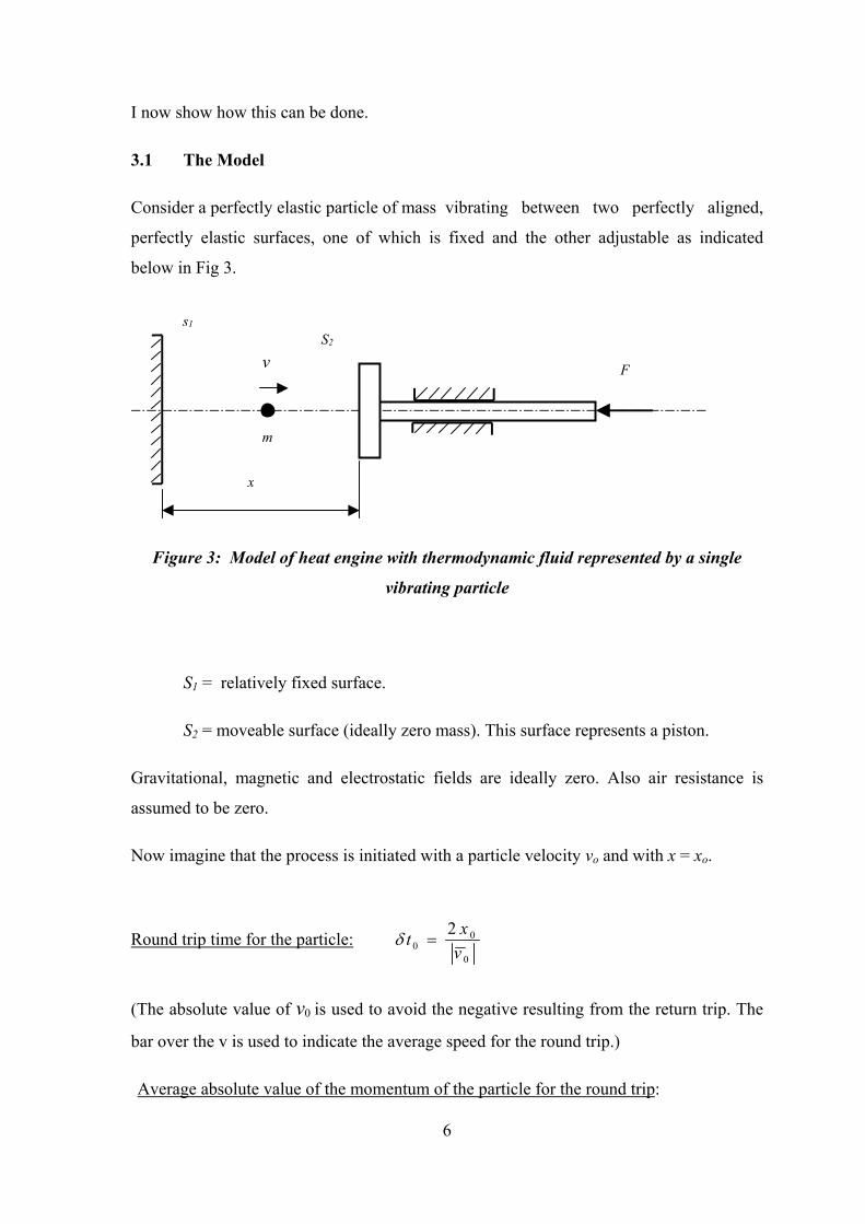
I now show how this can be done.
3.1 The Model
Consider a perfectly elastic particle of mass vibrating between two perfectly aligned,
perfectly elastic surfaces, one of which is fixed and the other adjustable as indicated
below in Fig 3.
s1
v
m
S2
F
x
Figure 3: Model of heat engine with thermodynamic fluid represented by a single
vibrating particle
S1 = relatively fixed surface.
S2 = moveable surface (ideally zero mass). This surface represents a piston.
Gravitational, magnetic and electrostatic fields are ideally zero. Also air resistance is
assumed to be zero.
Now imagine that the process is initiated with a particle velocity vo and with x = xo.
Round trip time for the particle: 0
00
2vxt =δ
(The absolute value of v0 is used to avoid the negative resulting from the return trip. The
bar over the v is used to indicate the average speed for the round trip.)
Average absolute value of the momentum of the particle for the round trip:
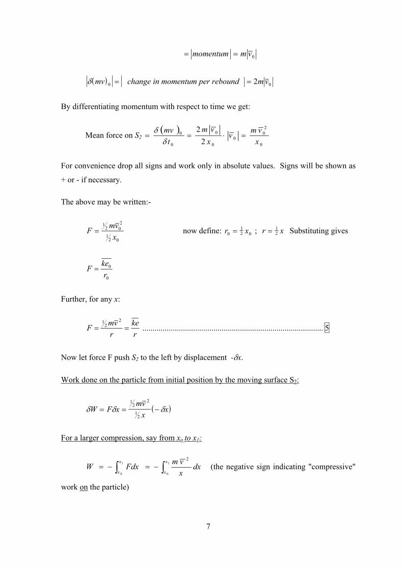
7
0vmmomentum ==
( )δ mv 0 = change in momentum per rebound 02 vm=
By differentiating momentum with respect to time we get:
Mean force on S2 ( )
0
20
00
0
0
0
22
xvmv
xvm
tmv
=⋅==δ
δ
For convenience drop all signs and work only in absolute values. Signs will be shown as
+ or - if necessary.
The above may be written:-
02
1
202
1
xvmF = now define: r x0
12 0= ; r x= 1
2 Substituting gives
0
0
rkeF =
Further, for any x:
rke
rvmF ==
22
1......................................................................................... 5
Now let force F push S2 to the left by displacement -δx.
Work done on the particle from initial position by the moving surface S2:
( )δ δ δW F xmv
xx= = −
12
2
12
For a larger compression, say from xo to x1:
∫∫ −=−= 1
0
1
0
2x
x
x
xdx
xvmFdxW (the negative sign indicating "compressive"
work on the particle)
8
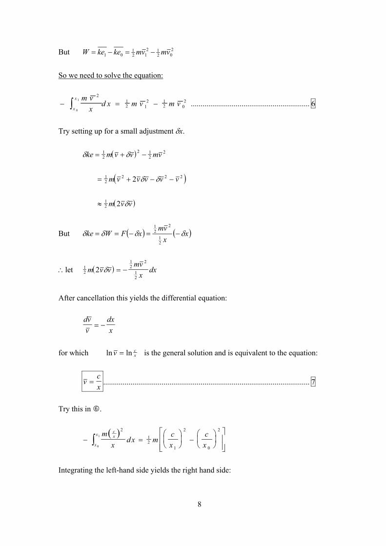
But 202
1212
101 vmvmkekeW −=−=
So we need to solve the equation:
− = −∫m v
xd x m v m v
x
x 212 1
2 12 0
2
0
1............................................................. 6
Try setting up for a small adjustment δx.
( )δ δke m v v mv= + −12
2 12
2
( )= + − −12
2 2 22m v v v v vδ δ
( )≈ 12 2m v vδ
But ( ) ( )xxvm
xFWke δδδδ −=−==21
221
∴let ( )12
12
2
12
2m v vmv
xdxδ = −
After cancellation this yields the differential equation:
dvv
dxx
= −
for which ln lnv cx= is the general solution and is equivalent to the equation:
vcx
= .......................................................................................................... 7
Try this in .
( )
− =
−
∫m
xd x m
cx
cx
cx
x
x2
12
1
2
0
2
0
1
Integrating the left-hand side yields the right hand side:

9
− = −
∫m c
xd x m c
x xx
x23
12
2
12
02
1 1 10
1
So equation 7 can now be accepted.
Now vcx0
0=
∴ =c x v0 0
( )
∴ =vx v
x0 0 ............................................................................................ 7.1
Also ( )2
200
212
21
xvxmvmke ==
Or substituting r = 1/2 x:
( )vx v
rr v
r=
× = ×0 0
0 021 1
( )ke mx v
rm r v
r=
=1
20 0
2
212 0 0
2
221 1
Note: Both velocity and kinetic energy tend to ∞ as r → 0 during an isentropic
compression.
3.2 Model of the Stirling Cycle:
Now consider, by analogy, a Stirling Cycle carried out on the particle.
1. By analogy, an isothermal process would correspond to constant ke based on the
kinetic theory of gases.
2. Constant volume heating (by analogy) would be where r is held constant and ke is
increased by introduction of external energy (say at surface S1) to increase v . Vice
versa for constant volume cooling.

10
s1 (capable of exchangingenergy with the particle.)
v
m
S2
Fc
xe
xc
Fe
Figure 4: Model of heat engine applied to Stirling Cycle
Commence the cycle at xe with particle velocity = lv and compress from xe to xc.
Work of compression (C)
∫∫
−=−=−= c
e
x
xe
cl
lc x
xvmdxxvmdxF ln2
2
Increase particle velocity to uv . By analogy, this would correspond to regeneration.
Energy of regeneration (R)
( )2221
lu vvm −=
Useful work of expansion (W)
∫ ∫ === e
c
x
xc
eu
ue x
xvmdxxvmdxF ln2
2
Energy of degeneration (D)
( )2221
lu vvm −=

11
The physical description and interpretation of the analogy is left to the reader.
Cycle efficiency
W
CWs
−=η
c
e
c
e
c
e
xx
u
xx
lxx
u
vmvmvm
lnlnln
2
22 −=
After cancellation,
2
22
u
lus v
vv −=η ...................................................................................... 8
The above formula, according to the kinetic theory of gases* is analogous to the Carnot
formula: u
lus T
TT −=η
*Note: The kinetic theory of gases gives the following relationship between the absolute
temperature of a gas and the mean velocity of the particles:
2
3v
kmT =
where: T = absolute temperature of the gas
m = molecular (particle) mass
k = the Boltzmann constant
particlestheofvelocitysquaremeanthev =2
Carnot Cycle
Similarly the Carnot cycle η may be derived.
12
3.3 Discussion of the above analysis of the vibrating particle model
The above vibrating particle model is a purely mechanical model. From this model, the
Carnot cycle efficiency has been derived. This indicates that the limitations of the second
law of thermodynamics are not mysterious and that the Carnot cycle efficiency limitations
are, in fact, simply caused by the mechanical-physical mode of transformation of energy
from heat to work via a pulsating volume of thermodynamic fluid.
The need to employ a cycle and the consequent need to reject some of the heat energy
received during some parts of the cycle, during the "compression" part of the cycle,
relates to the fact that the thermodynamic fluid is gas. Because this gas is contained under
pressure it therefore reacts against the piston during compression and requires work of
compression while it simultaneously rejects the work of compression to the sink so as to
avoid an increase in its "internal energy".
I have not overlooked the fact that the case of the single particle, above and even the more
widely representative case of and ideal gas (governed by the kinetic theory) based heat
engine cycles are not generally representative of all heat engine cycles. They do not, for
example represent two phase cycles or solid state heat engine cycles. What I do wish to
focus on is the mechanism that the vibrating particle model reveals and the fact that this
is clearly the governing mechanism for the ideal gas based heat engine and is therefore
likely to be more general.
Later, other cases may be investigated to see if the other cases are also governed by the
same mechanism. Since the body of knowledge contained in classical thermodynamics
already shows the generality of the Carnot limitation to all heat engines (whether two
phase or solid state etc.) we already know that further investigation will support our case.
Unfortunately, however the classical thermodynamics does not readily reveal our
mechanism in a way that is meaningful to an engine designer.
4.0 IDEAL GAS CYCLE MODEL ANALYSED ON A ln T - ln ν
DIAGRAM

13
I now present the second of my two models. This is a mathematical model that is
illustrated on a ln-ln diagram.
4.1 Background to the ln T - ln ν DIAGRAM
After having reached the conclusions of the vibrating particle model of the previous
section of this report, I reasoned that the traditional ideal gas cycle model, well known in
engineering textbooks effectively supports the same ideas. However the traditional
presentation in textbooks does not have a design approach to it. I reasoned that an
engineering designer would develop a method with the following lines of reasoning and
with the following questions in mind.
• Heat engines are modeled with ideal cycles for ideal gases on diagrams.
• Cycles may be manipulated and analysed mathematically.
• "Manipulation" might include breaking down a cycle into elemental components and
reconstructing and equivalent cycle or mathematical transformation.
• What type of diagram would be the best for the manipulation process?
• Then, can a method of manipulation be found which will lead to the "best" cycle. This
may be the one with the highest efficiency. Such a process would be an optimization
process.
• Traditional textbooks simply present and analyse a number of standard cycles: Carnot,
Diesel, Stirling etc. They discuss the practicalities, advantages and disadvantages of
each of these cycles. This traditional textbook approach lacks any suggestion of
optimization processes.
With the above thoughts in mind I now outline my preliminary ideas and assumptions and
then present my derivation.
4.2 Preliminary ideas and assumptions
I include with my preliminary ideas some of the basic laws and theories from the
textbooks.

14
4.2.1 Processes and the First Law
For a heat engine as in section 2.2, consider the application of the First Law to a number
of elementary reversible changes in the system. If the cylinder is always pressurized then,
work is done when the piston moves to the right, whilst work must be rejected (done on
the system), in order to move it to the left.
Heat energy may be introduced concurrently whilst work is being done by the engine.
Then three possibilities arise:-
(i) The heat energy may exceed the work, in which case the internal energy of
the fluid is increased.
d Q d U d Win c rsu p = +
(e.g., constant pressure process)
(ii) The heat energy may just equal the work done:
d Q d Ws u p =
(this is the isothermal process)
(iii) The heat energy supplied may be less than the work done:
decrdUdWdQ −=sup
(in this case internal energy is being given up to contribute to the work
done by the engine.)
Conversely, whilst the piston is doing work on the gas, heat energy may be rejected.
Then, once again, there are three possible outcomes:-
(i) Work done on the gas is less than heat energy rejected:
decrrej dUdQdW −=
(ii) Work done on the gas just equals heat energy rejected:
d W d Q r e j=
(iii) Work done on the gas is greater than the rejected heat energy:
decrrej dUdQdW +=

15
Other special cases:-
(i) Isentropic:
dU dW=
(ii) Constant volume:
dQ dU=
4.2.2 Constant volume and isothermal processes
These processes are special in that, in the first, no work crosses the boundary, whilst in
the second, one hundred percent of the supplied heat energy crosses the boundary as work
done. An interesting account of this process is given in Pierce, (1970) pp 345-348.
4.2.3 Regenerators
Part of the gross work of a cycle may be stored as energy in a flywheel and later returned
to the fluid. Similarly, heat energy may be stored in a regenerator and returned provided
the temperature of regenerator and fluid are suitable to cause energy flow.
4.2.4 Capacitor Analogy
The regenerator may be considered to be a thermal capacitor and the fluid itself acts as a
thermal capacitor. Then an engine may be represented in a diagrammatic form as shown
below.
REJECTEDHEATENERGY
MECHANICALWORK OUTPUT
HEATENERGYINPUT
MECHANICAL
FLYWHEEL
THERMAL
“CAPACITORS”
HEAT ENGINE
Figure 5: Model of a heat engine having both mechanical flywheel and thermal
capacitors
16
4.2.5 Zeroth Law of Thermodynamics
(Cardwell, D. S. L., 1971, p 8; Reynolds, W. C., 19xx, p62)
4.2.6 Temperature
(Cardwell, D. S. L., p 8; Reynolds, W. C., pp 61-66)
4.2.7 Internal Energy: (Pierce, 1970, Ch 13)
4.2.8 Equilibrium: (Reynolds, pp 59,60)
4.2.9 Entropy - history of the discovery of: (Cardwell, pp 260-276)
4.2.10 Open and Closed Cycles: (Mahew and Rogers, 1967, pp 43,44)
4.2.11 Kinetic Theory of Gases: (Lewitt, 1946, pp 435 to 467; Pierce, pp230 to 236,
Reynolds, pp 226 to 231)
4.2.12 Pressure:
Generally in a heat engine pressure results from the rebounding of molecules on the walls
of the engine etc.
In the liquid state or solid state, matter may exert pressure as a result of repulsive forces
between molecules and rebounding of vibrating molecules (Pierce, pp 420 to 422).
Ideal gas pressure may be diminished by attractive forces between atoms and molecules.
It is evident, however that both pressure and temperature increase with internal energy.
(Pierce pp 322 to 324, 232, 3)
5. THE TECHNIQUE FOR DERIVING ULTIMATE HEAT
ENGINE EFFICIENCY.
The technique is now presented. It commences by considering an ideal gas as proposed by
the Kinetic Theory. The Zeroth and First Laws are accepted.
5.1 Assumptions

17
It is accepted that for an engine to perform non-trivial work, the thermodynamic fluid
must pass through a cycle in the accepted sense having positive area on a Pv or Tv
diagram and for convenience, with clockwise sense. All processes to follow are assumed
to be reversible as it can be shown reversible processes only detract from efficiency.
Mathematically, the Kinetic Theory supports the Characteristic Equation for Ideal Gases.
PvRM
To=
............................................................................... (1a)
or Pv RT= .....................................................................................(1b)
Where:-
P = absolute pressure of the gas
v = specific volume
Ro = universal gas constant
M = mean relative molecular mass
R = specific gas constant
T = absolute temperature
From which:-
PRv
T= × ....................................................................................(2)
(i.e. pressure is proportional to temperature for a particular specific volume.)
A further useful consequence of the Kinetic Theory is that Cv is independent of v or that u
(internal energy) depends only on T
ie: u u C To v= + ∆ ................................................................ (3a)
or ∆ ∆u C Tv= .....................................................................(3b)
Equations (2) and (3a and b) are now used along with the concepts at the beginning of this
section to derive "ultimate efficiency".
18
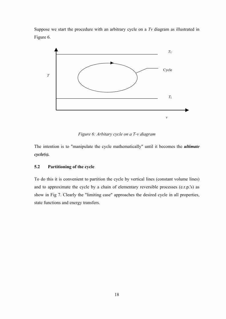
Suppose we start the procedure with an arbitrary cycle on a Tv diagram as illustrated in
Figure 6.
TU
TL
CycleT
v
Figure 6: Arbitary cycle on a T-v diagram
The intention is to "manipulate the cycle mathematically" until it becomes the ultimate
cycle(s).
5.2 Partitioning of the cycle
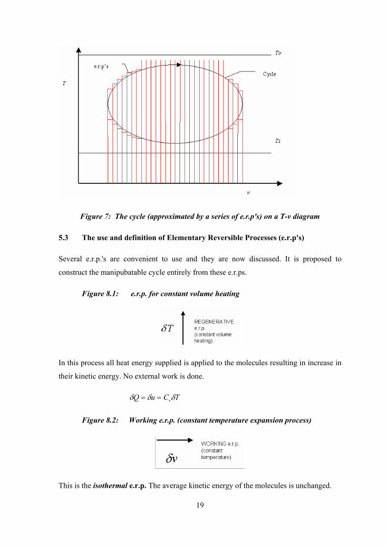
To do this it is convenient to partition the cycle by vertical lines (constant volume lines)
and to approximate the cycle by a chain of elementary reversible processes (e.r.p.'s) as
show in Fig 7. Clearly the "limiting case" approaches the desired cycle in all properties,
state functions and energy transfers.
19
Figure 7: The cycle (approximated by a series of e.r.p's) on a T-v diagram
5.3 The use and definition of Elementary Reversible Processes (e.r.p's)
Several e.r.p.'s are convenient to use and they are now discussed. It is proposed to
construct the manipubatable cycle entirely from these e.r.ps.
Figure 8.1: e.r.p. for constant volume heating
In this process all heat energy supplied is applied to the molecules resulting in increase in
their kinetic energy. No external work is done.
δ δ δQ u C Tv= =
Figure 8.2: Working e.r.p. (constant temperature expansion process)
This is the isothermal e.r.p. The average kinetic energy of the molecules is unchanged.

20
All heat energy supplied is converted to work (which may be used at the "shaft" or
temporarily stored as energy in the flywheel).
PdvdWQ ==δ
Figure 8.3: Working Isentropic e.r.p. (isentropic expansion process)
In this case work done is provided only by degeneration of the kinetic energy of the
molecules (i.e. no external heat energy supplied).
For this case to occur it is evident that the molecular k.e. must have been provided prior
(in the cycle) to the event and that:-
δ δ δQ C T P vprior to the event v− − − = =
Figure 8.4: Degenerative e.r.p. (constant volume)
In this process molecular k.e. degenerates and no work is done. It would appear that this
represents a total loss of heat energy. However, assuming a perfect regenerator may be
devised, all such energy may be stored and used for corresponding regenerative e.r.p.'s.
δ δQ C Tvdeg =
Figure 8.5: Compressive e.r.p (isothermal compression)
In order to repeat the cycle it is evidently necessary to reduce v (recompress the gas) and
by the first law this requires that:

21
vPWQ rejrej δδδ ==
During this e.r.p., stored mechanical energy is transferred to the gas and since the internal
energy of the gas is invariant, the energy is immediately transferred out as rejected heat
energy! Tentatively we may consider this heat energy as recoverable, but later we see that
it is not recoverable at TL.
Figure 8.6: Compressive Isentropic e.r.p.
Here the flywheel energy is used to regenerate molecular k e.
No external heat energy is supplied or rejected.
For convenience the e.r.p.'s are now labelled as follows:
e.r.p label
Regenerative R
Working W
Isentropic working WI
Degenerative D
Compressive C
Isentropic compression CI
5.4 Partitioning and constructing of a cycle using e.r.p's
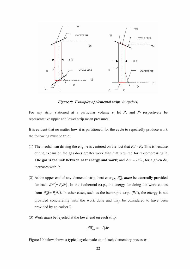
Now consider particular strips of a cycle (Figure 9). The strips are each identified at a
particular specific volume, v and strip mean upper and lower temperatures, Tu and Tl.
22
Figure 9: Examples of elemental strips in cycle(s)
For any strip, stationed at a particular volume v, let Pu and Pl respectively be
representative upper and lower strip mean pressures.
It is evident that no matter how it is partitioned, for the cycle to repeatedly produce work
the following must be true:
(1) The mechanism driving the engine is centered on the fact that Pu > Pl. This is because
during expansion the gas does greater work than that required for re-compressing it.
The gas is the link between heat energy and work; and δ δW P v= , for a given δv,
increases with P.
(2) At the upper end of any elemental strip, heat energy, δQ, must be externally provided
for each ( )vPW uδδ = . In the isothermal e.r.p., the energy for doing the work comes
from ( )vPQ uδδ = . In other cases, such as the isentropic e.r.p. (WI), the energy is not
provided concurrently with the work done and may be considered to have been
provided by an earlier R.
(3) Work must be rejected at the lower end on each strip.
δ δW P vrej l= −
Figure 10 below shows a typical cycle made up of such elementary processes:-

23
Figure 10: Examples of elementary reversible processes approximating an engine cycle
For this cycle the following may be observed to be valid:
Every W requires δQ = δW
Every WI requires δQ = δW from one or more R's matching the fall in T during the WI
At best every R should be provided by a D; except when R provides WI.
Note: Since δ δQ C Tv= is invariant with v we can match D's with R's.
Hence for every strip, at best:-
dat.supplieminimum.he
doneworknetstrip
..=η
=−P v P v
P vu l
u
δ δδ
=−P PP
u l
u.............................................................................(4)
Equations (2) and (4) ⇒

24
η stripu l
u
T TT
=−
..........................................................................(5)
If a source at TU is available and a sink at TL then:-
maximum η s tr ipU L
U
T TT
=−
......................................................................(6)
Considering the entire cycle, an obvious solution for which ηcycle is maximised is that
cycle for which all strips have Tu = TU and Tl = TL , i.e. the Stirling cycle.
Figure 11: The Stirling cycle as a cycle of ultimate efficiency
The Stirling cycle may therefore be considered to be the most fundamental solution to
the question of which cycle(s) have ultimate efficiency.
At first it may appear to be the only solution to the problem, as introduction of strips
where Tu<TU or Tl>TL would seem to detract from efficiency.
Note that for the Stirling cycle all D must (in theory) be used for R.
5.5 Transforming to a ln T - ln v chart to conveniently find ALL cycles of Carnot
efficiency
For a further study to look for other cycles having ultimate efficiency it becomes
convenient to transform the problem to a ln T - ln v chart.
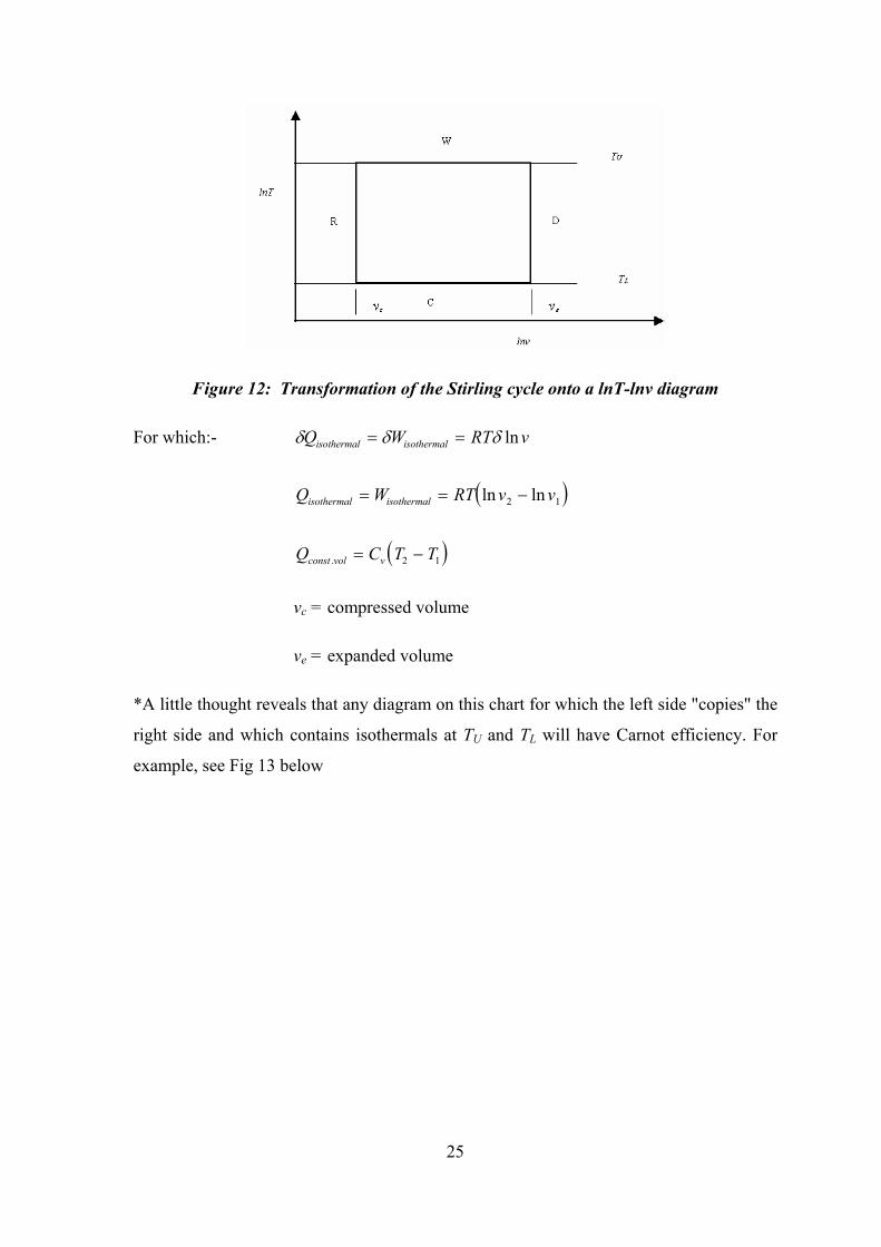
25
Figure 12: Transformation of the Stirling cycle onto a lnT-lnv diagram
For which:- δ δ δQ W RT visothermal isothermal= = ln
( )Q W RT v visothermal isothermal= = −ln ln2 1
( )Q C T Tconst vol v. = −2 1
vc = compressed volume
ve = expanded volume
*A little thought reveals that any diagram on this chart for which the left side "copies" the
right side and which contains isothermals at TU and TL will have Carnot efficiency. For
example, see Fig 13 below

26
Figure 13: Other cycles having Carnot efficiency
For which intermediate C's may in theory be provided by flywheel energy stored from
matching intermediate W's thereby eliminating the apparent need for external
compression energy at the C's. In a similar manner heat the matching C's may (in theory)
provide energy for the matching W's.
6. THE COMMON CYCLES AND SOME COMMENTS
By consideration of a number of such examples and by extension to any number of
matching steps (even approaching an infinite number) one may arrive at the statement *.
6.1 The chart below summarizes the most common cycles having ηcarnot.
Figure 14: Common cycles having Carnot efficiency
27
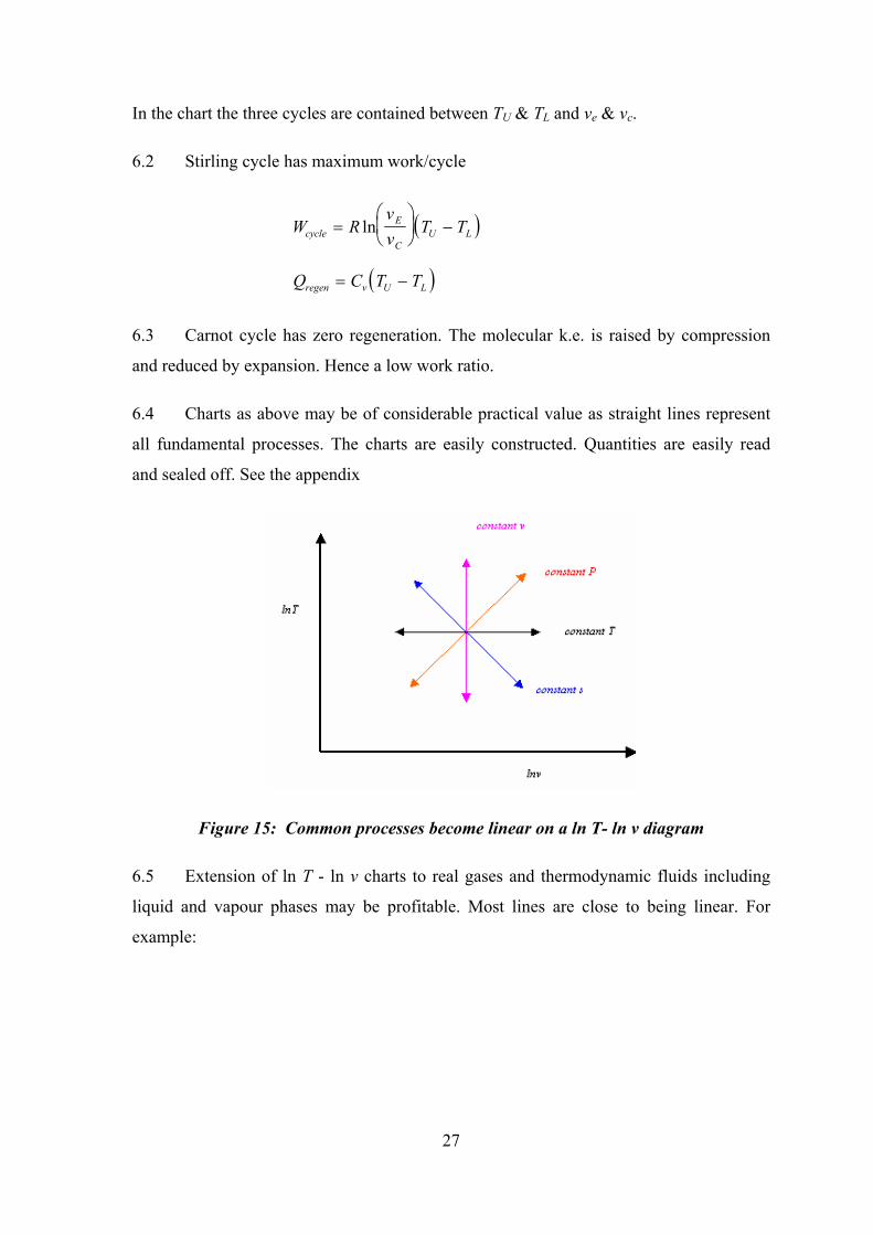
In the chart the three cycles are contained between TU & TL and ve & vc.
6.2 Stirling cycle has maximum work/cycle
( )W Rvv
T TcycleE
CU L=
−ln
( )Q C T Tregen v U L= −
6.3 Carnot cycle has zero regeneration. The molecular k.e. is raised by compression
and reduced by expansion. Hence a low work ratio.
6.4 Charts as above may be of considerable practical value as straight lines represent
all fundamental processes. The charts are easily constructed. Quantities are easily read
and sealed off. See the appendix
Figure 15: Common processes become linear on a ln T- ln v diagram
6.5 Extension of ln T - ln v charts to real gases and thermodynamic fluids including
liquid and vapour phases may be profitable. Most lines are close to being linear. For
example:

28
Figure 15: Typical lines for real fluids on a lnT -ln v diagram
6.6 Three-dimensional charts could be useful. Construction of P and u surfaces to the
bases ln T vs ln v yields substantially flat surfaces compared to the traditional curved
surfaces. These surfaces would seem to be of considerable aid in understanding the
various fluids and cycles.
7. FURTHER WORK TO BE CARRIED OUT:
So far this paper has only considered ideal gases and it in no way explains ultimate
efficiency for engines using real fluids. Figure 15 suggests a breakdown in the reasoning,
as a constant temperature process does not infer constant internal energy during the
vapour phase. Also during the vapour phase T is not proportional to P when v is fixed.
However, in general terms it is evident that T and P increase together at constant v and
hence, if a real cycle is partitioned into strips, greater work potential will exist at the upper
end of the strips than the lower end.
Evidently higher temperature is caused by higher molecular k.e. and it follows that the
higher molecular k.e. Will produce higher molecular momentum and hence higher
pressure which means greater δW for a given δv.
The question of regeneration is not easily answerable and the simple relationships for an
ideal gas do not hold for either work potential or regeneration.

29
Nevertheless, it is suspected that the model may be modified to include real fluids and that
some general statement(s) based on the energy relationships of molecules and liquids
involving attractive and repulsive molecular forces and the structure of matter will show
that real substances can only at best produce the efficiency shown for an ideal gas. It is
hoped that extension of the theory will produce results that greatly aid the understanding
with regard to real cycles.
8. CONCLUSIONS
8.1 This paper has taken a fresh look at the kinetic theory model of an ideal gas by
investigating some consequences of modeling a gas by a single "spherical-elastic"
particle. It has then applied this model to the simple well-known source-sink
model of a heat engine and shown that this model produces the Carnot limiting
efficiency. Thus the Carnot efficiency is demonstrated with only two assumptions:
use of a Newtonian-mechanical model and that absolute temperature is related
directly to the kinetic energy of the particle. The complexity of modeling the gas
by using the mean properties of an immense number of molecules in a three
dimensional container is shown to be not necessary to obtain the Carnot limitation.
8.2 The least benefit of 8.1 is that it provides an educationally beneficial way of
viewing the Carnot limitation, particularly for engineers.
8.3 A possible greater benefit of 8.1 is that it may have proved the Carnot limitation
from a simple Newtonian-mechanical model (the Kinetic Theory of Gases). In
which case, since the Carnot limitation is a corollary of the Second Law of
Thermodynamics it will have reduced the Second Law to a consequence of the
Kinetic Theory of Gases without the need to introduce the statistically derived
concept of entropy. This would be a startling discovery!
8.4 Having achieved 8.1 to 8.3, I then observe that the implications of the single
particle model are effectively extended to the entire Kinetic Theory of Gases with
all its refinements.
8.5 I then consider heat engine cycle diagrams for ideal gases. The mathematical
relationships producing these cycle diagrams are supported by the Kinetic Theory.
30
I construct a heat engine cycle from e. r. p's (infinitesimally small reversible
processes) and mathematically manipulate this cycle to find all cycles having
Carnot efficiency. For convenience, a ln T-ln v diagram is used and I show that on
such a diagram, all these cycles have upper and lower isothermals of equal length
which are connected by a left and a right process or series of processes that are
geometrically identical.
8.6 Finally, I now point out that the central cause of the Carnot limitation is that
during a heat engine cycle the gas must be expanded and recompressed or vice
versa. To any incremental expansion there must be a corresponding incremental
recompression in the same volume range. If one examines such an incremental
pair it is evident that for an ideal gas, the isothermal work output during the
incremental expansion is proportional to the absolute temperature as is the
isothermal energy rejected during the corresponding incremental compression.
This is simply because of the relationship between absolute temperature and mean
particle kinetic energy*, giving rise to proportionately greater work output than
energy rejection. Clearly some energy rejection must occur unless the sink
temperature is absolute zero.
*as well as particle velocity and consequences such as frequency of rebound of particles
on the work boundary giving rise to proportionately higher pressure.
References:
Bloch, Eugène, 1924, The Kinetic Theory of Gases, Methuen and Co. Ltd. London
Cardwell, D. S. L., 1971, From Watt to Clausius - The rise of thermodynamics in the
early industrial age, Heinemann London, ISBN: 0435541501
Rogers, G.F.C. & Mayhew, Y.R., (1967), Engineering Thermodynamics - Work and
Heat Transfer. Second Edition, (Longman)
Lewitt, E.H., (1946), Thermodynamics Applied to Heat Engines, Sixth Edition,
(Longman)
Pierce, James B., (1970), The Chemistry of Matter, (Houghton Mifflin Co., Boston)

31
Reynolds, William C., (19xx), Thermodynamics. Second Edition, (McGraw Hill)
Resnick, Robert, & Halliday David, (1966), Physics, (Wiley)
Masterton, W. L., & Sloweinski, E.J., (1973), Chemical Principles, (Saunders)