Embed Size (px)
Citation preview
Kalpakjian • SchmidManufacturing Engineering and Technology
© 2001 Prentice-Hall Page 14-1
CHAPTER 14
Forging of Metals
Kalpakjian • SchmidManufacturing Engineering and Technology
© 2001 Prentice-Hall Page 14-2
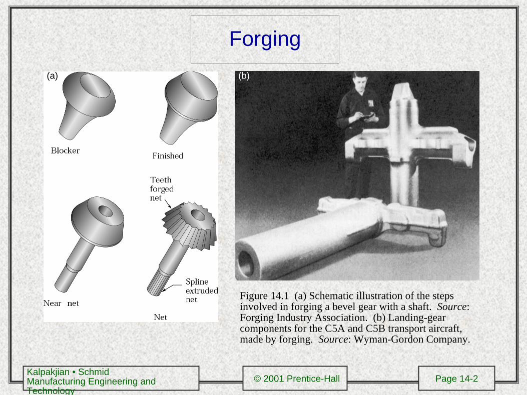
Forging(a) (b)
Figure 14.1 (a) Schematic illustration of the steps involved in forging a bevel gear with a shaft. Source: Forging Industry Association. (b) Landing-gear components for the C5A and C5B transport aircraft, made by forging. Source: Wyman-Gordon Company.
Kalpakjian • SchmidManufacturing Engineering and Technology
© 2001 Prentice-Hall Page 14-3
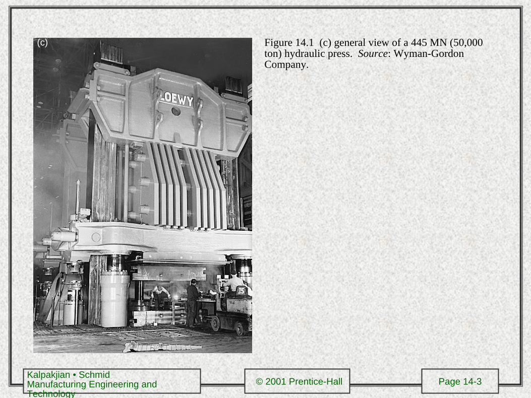
Figure 14.1 (c) general view of a 445 MN (50,000 ton) hydraulic press. Source: Wyman-Gordon Company.
(c)
Kalpakjian • SchmidManufacturing Engineering and Technology
© 2001 Prentice-Hall Page 14-4
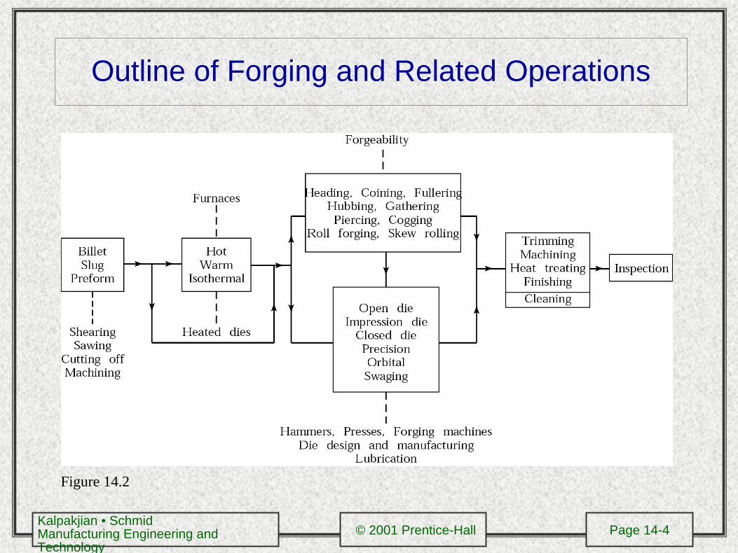
Outline of Forging and Related Operations
Figure 14.2
Kalpakjian • SchmidManufacturing Engineering and Technology
© 2001 Prentice-Hall Page 14-5
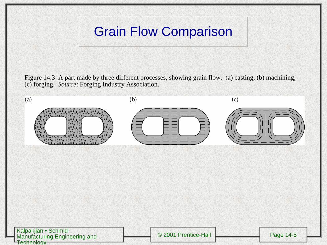
Grain Flow Comparison
Figure 14.3 A part made by three different processes, showing grain flow. (a) casting, (b) machining, (c) forging. Source: Forging Industry Association.
Kalpakjian • SchmidManufacturing Engineering and Technology
© 2001 Prentice-Hall Page 14-6
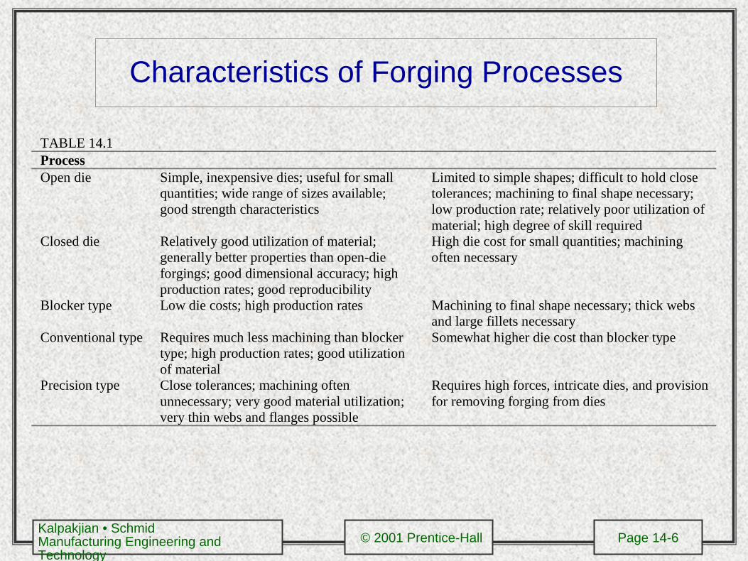
Characteristics of Forging Processes
TABLE 14.1ProcessOpen die Simple, inexpensive dies; useful for small
quantities; wide range of sizes available;good strength characteristics
Limited to simple shapes; difficult to hold closetolerances; machining to final shape necessary;low production rate; relatively poor utilization ofmaterial; high degree of skill required
Closed die Relatively good utilization of material;generally better properties than open-dieforgings; good dimensional accuracy; highproduction rates; good reproducibility
High die cost for small quantities; machiningoften necessary
Blocker type Low die costs; high production rates Machining to final shape necessary; thick websand large fillets necessary
Conventional type Requires much less machining than blockertype; high production rates; good utilizationof material
Somewhat higher die cost than blocker type
Precision type Close tolerances; machining oftenunnecessary; very good material utilization;very thin webs and flanges possible
Requires high forces, intricate dies, and provisionfor removing forging from dies
Kalpakjian • SchmidManufacturing Engineering and Technology
© 2001 Prentice-Hall Page 14-7
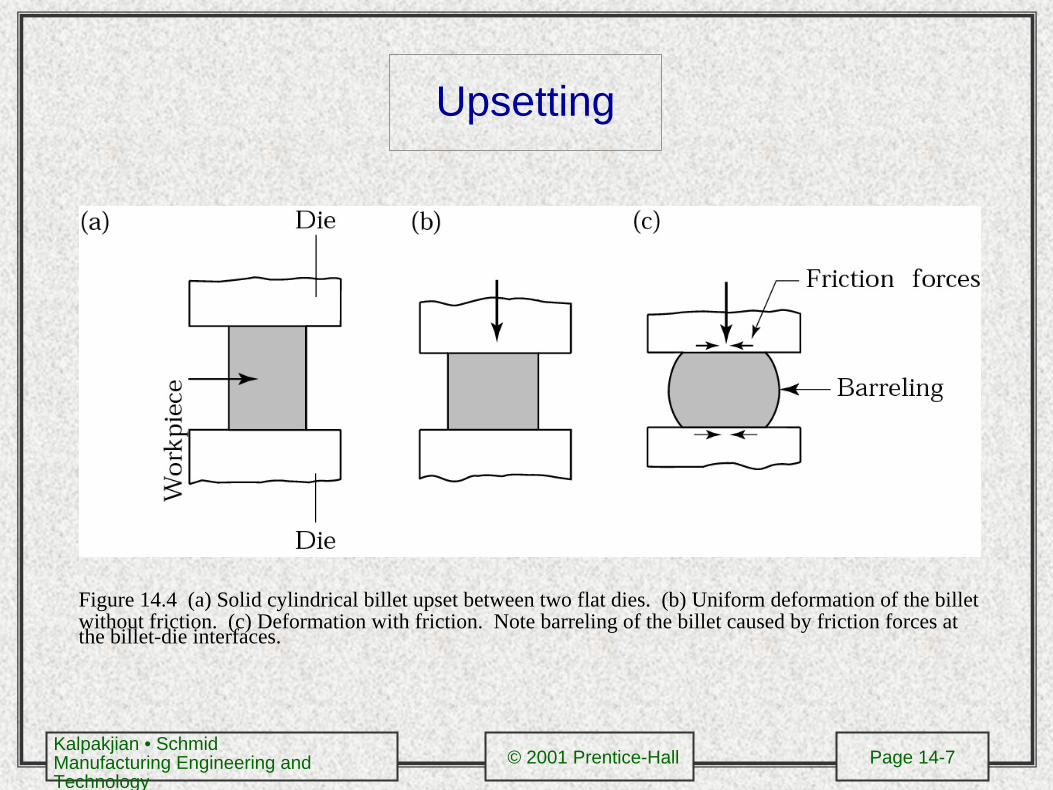
Upsetting
Figure 14.4 (a) Solid cylindrical billet upset between two flat dies. (b) Uniform deformation of the billet without friction. (c) Deformation with friction. Note barreling of the billet caused by friction forces at the billet-die interfaces.
Kalpakjian • SchmidManufacturing Engineering and Technology
© 2001 Prentice-Hall Page 14-8
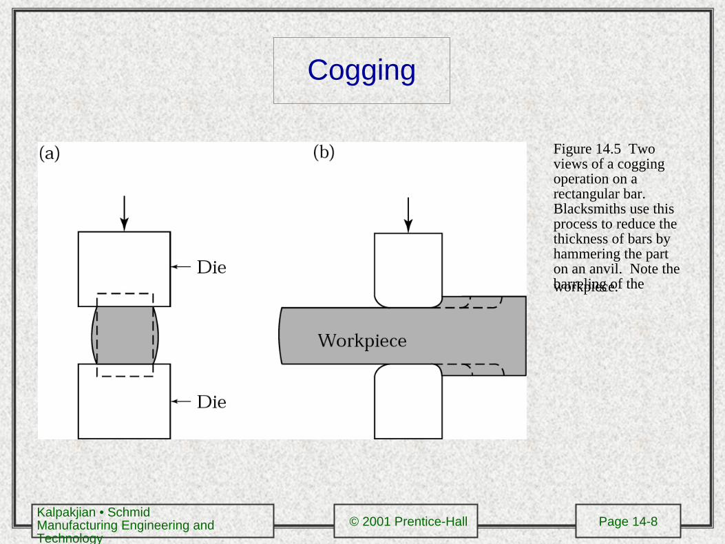
Cogging
Figure 14.5 Two views of a cogging operation on a rectangular bar. Blacksmiths use this process to reduce the thickness of bars by hammering the part on an anvil. Note the barreling of the workpiece.
Kalpakjian • SchmidManufacturing Engineering and Technology
© 2001 Prentice-Hall Page 14-9
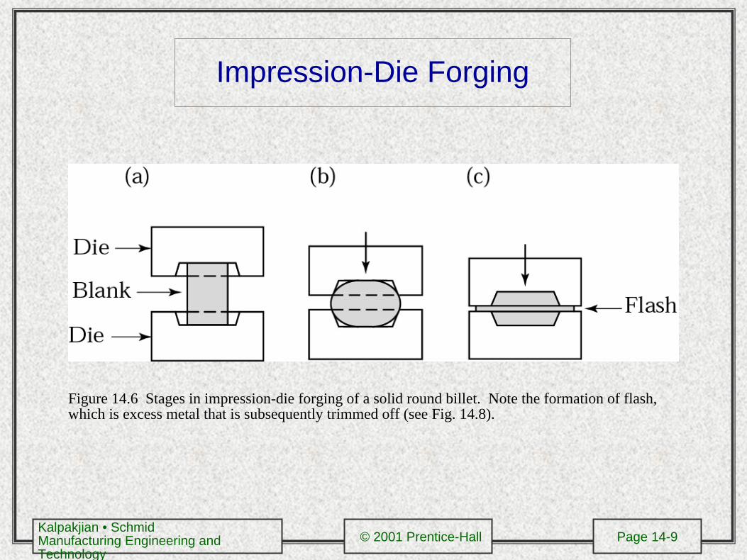
Impression-Die Forging
Figure 14.6 Stages in impression-die forging of a solid round billet. Note the formation of flash, which is excess metal that is subsequently trimmed off (see Fig. 14.8).
Kalpakjian • SchmidManufacturing Engineering and Technology
© 2001 Prentice-Hall Page 14-10
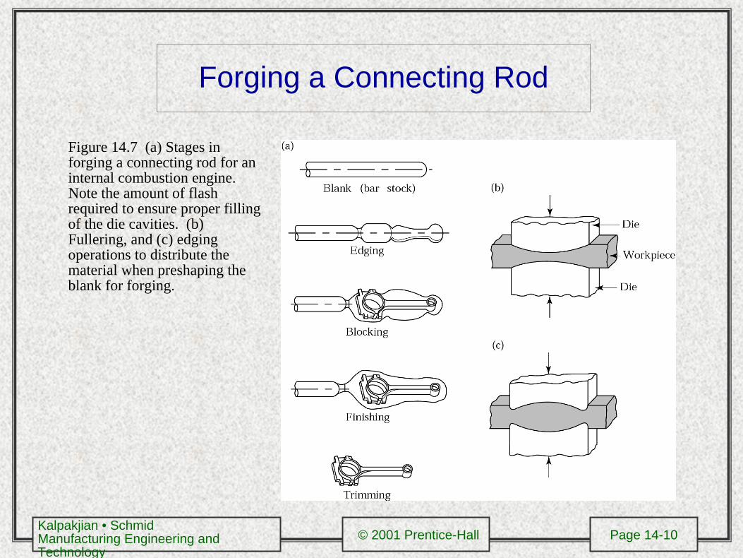
Forging a Connecting Rod
Figure 14.7 (a) Stages in forging a connecting rod for an internal combustion engine. Note the amount of flash required to ensure proper filling of the die cavities. (b) Fullering, and (c) edging operations to distribute the material when preshaping the blank for forging.
Kalpakjian • SchmidManufacturing Engineering and Technology
© 2001 Prentice-Hall Page 14-11
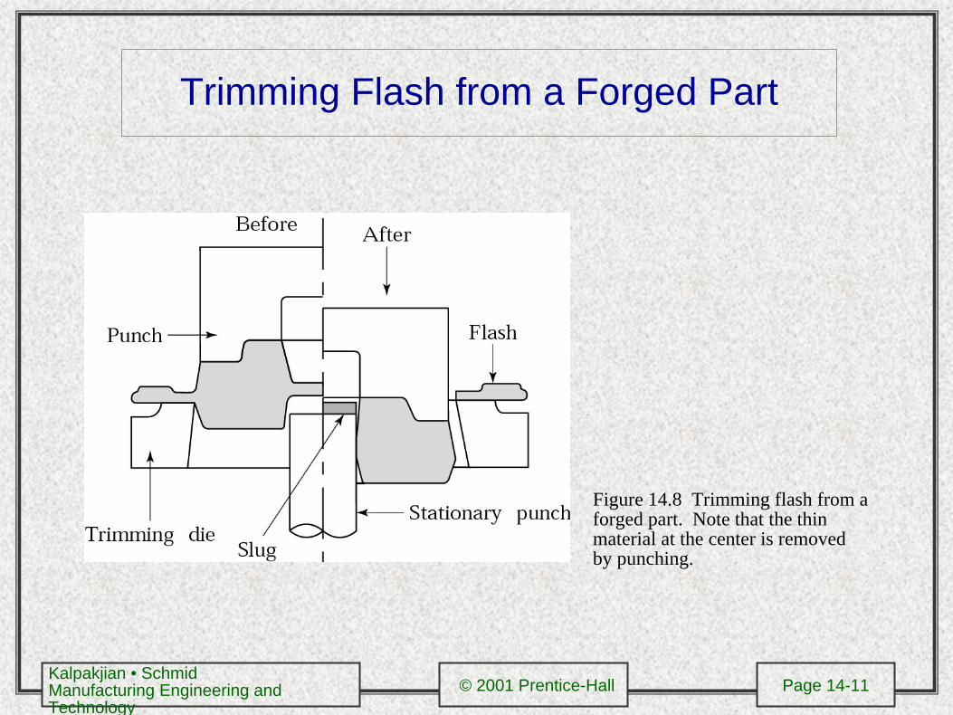
Trimming Flash from a Forged Part
Figure 14.8 Trimming flash from a forged part. Note that the thin material at the center is removed by punching.
Kalpakjian • SchmidManufacturing Engineering and Technology
© 2001 Prentice-Hall Page 14-12
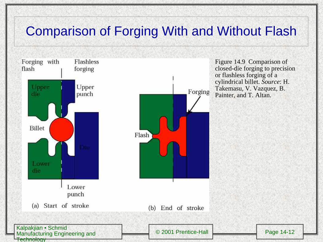
Comparison of Forging With and Without Flash
Figure 14.9 Comparison of closed-die forging to precision or flashless forging of a cylindrical billet. Source: H. Takemasu, V. Vazquez, B. Painter, and T. Altan.

Kalpakjian • SchmidManufacturing Engineering and Technology
© 2001 Prentice-Hall Page 14-13
Coining
Figure 14.10 (a) Schematic illustration of the coining process. the earliest coins were made by open-die forging and lacked sharp details. (b) An example of a coining operation to produce an impression of the letter E on a block of metal.
Kalpakjian • SchmidManufacturing Engineering and Technology
© 2001 Prentice-Hall Page 14-14
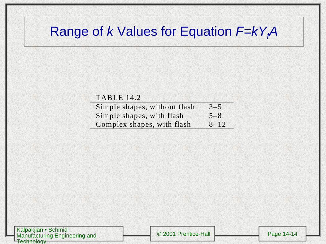
Range of k Values for Equation F=kYfA
TABLE 14.2Simple shapes, without flash 3–5Simple shapes, with flash 5–8Complex shapes, with flash 8–12
Kalpakjian • SchmidManufacturing Engineering and Technology
© 2001 Prentice-Hall Page 14-15
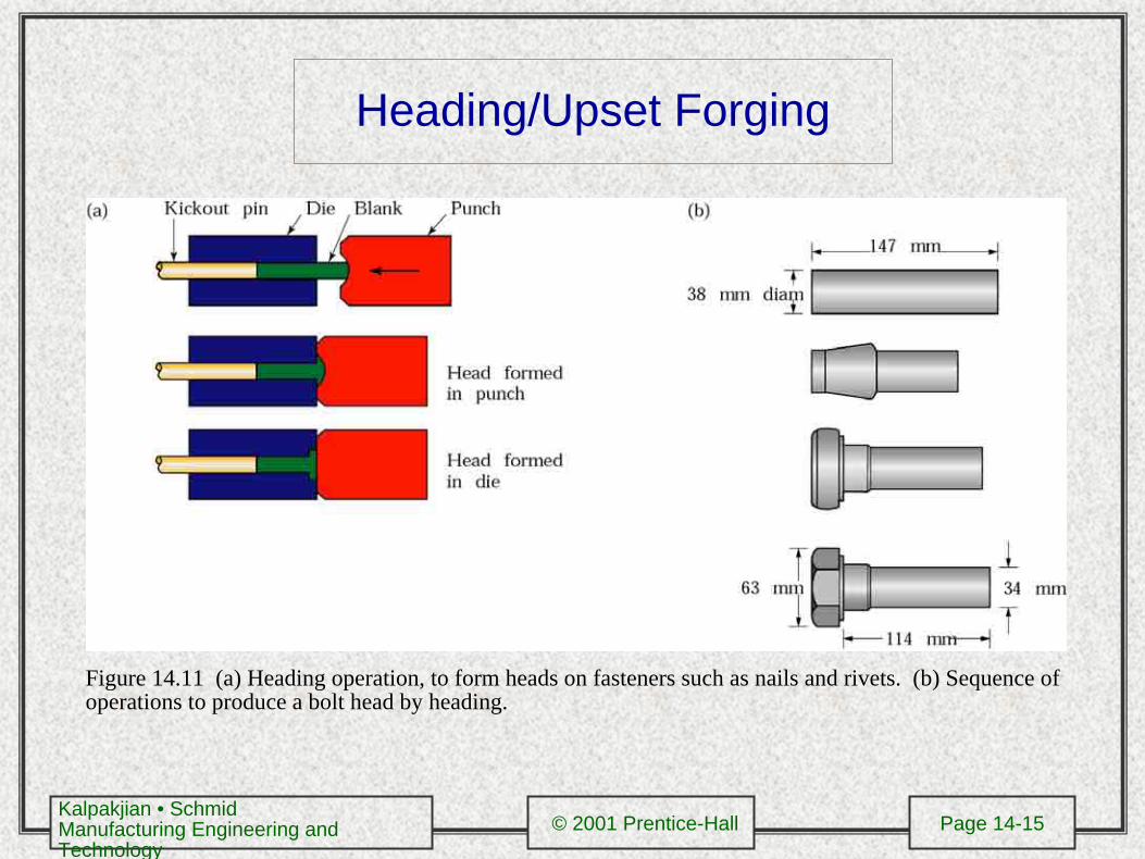
Heading/Upset Forging
Figure 14.11 (a) Heading operation, to form heads on fasteners such as nails and rivets. (b) Sequence of operations to produce a bolt head by heading.
Kalpakjian • SchmidManufacturing Engineering and Technology
© 2001 Prentice-Hall Page 14-16
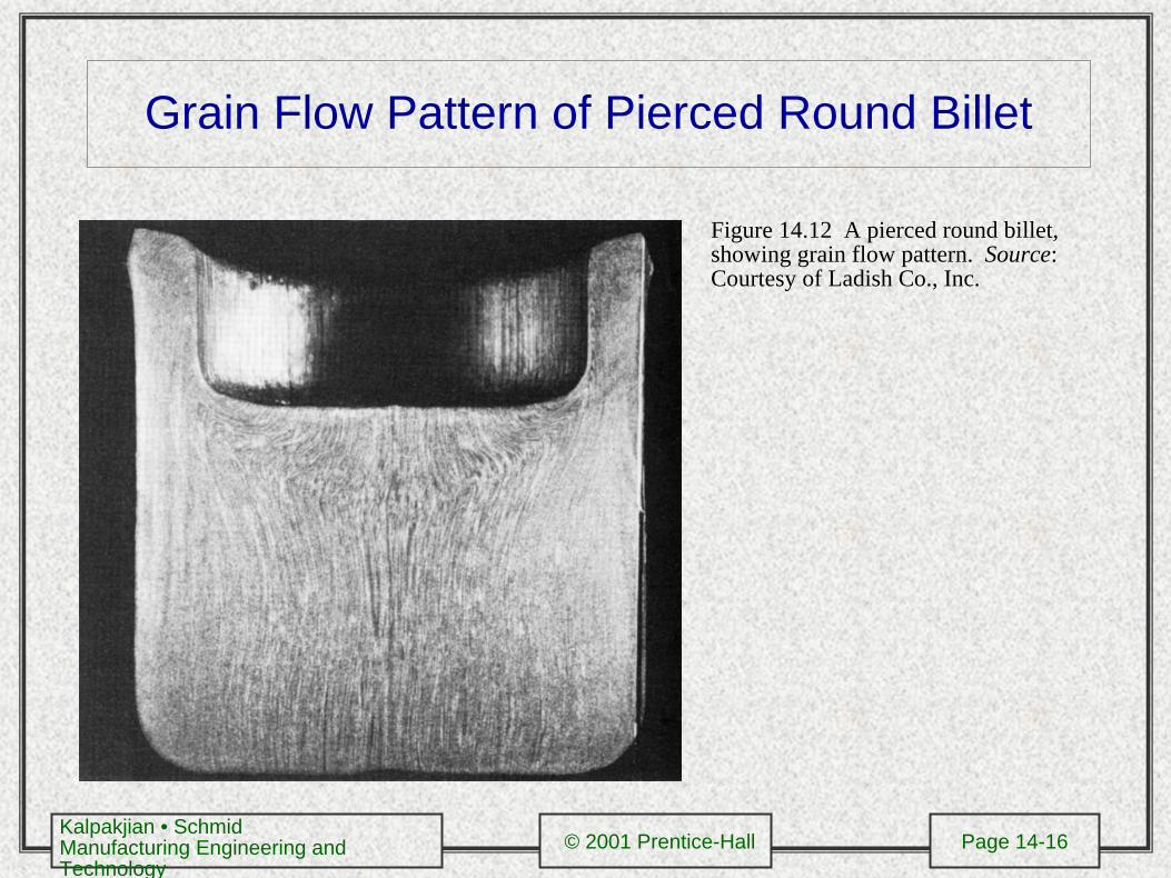
Grain Flow Pattern of Pierced Round Billet
Figure 14.12 A pierced round billet, showing grain flow pattern. Source: Courtesy of Ladish Co., Inc.
Kalpakjian • SchmidManufacturing Engineering and Technology
© 2001 Prentice-Hall Page 14-17
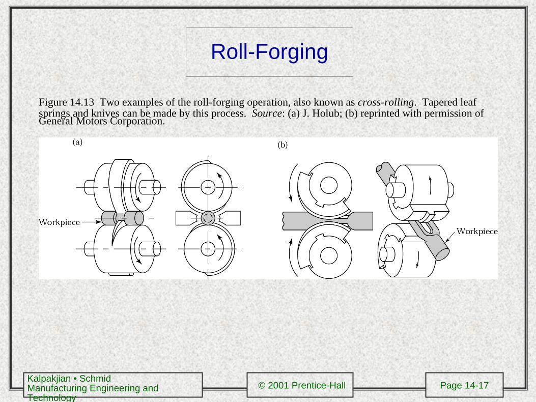
Roll-Forging
Figure 14.13 Two examples of the roll-forging operation, also known as cross-rolling. Tapered leaf springs and knives can be made by this process. Source: (a) J. Holub; (b) reprinted with permission of General Motors Corporation.
Kalpakjian • SchmidManufacturing Engineering and Technology
© 2001 Prentice-Hall Page 14-18
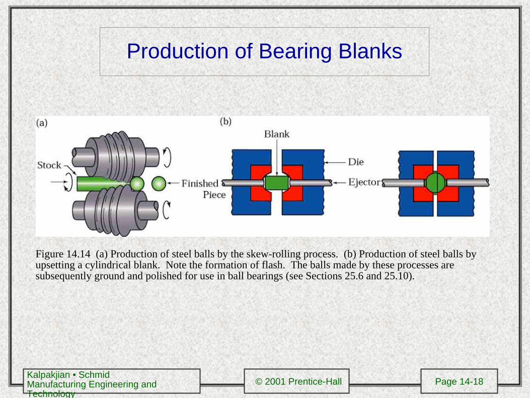
Production of Bearing Blanks
Figure 14.14 (a) Production of steel balls by the skew-rolling process. (b) Production of steel balls by upsetting a cylindrical blank. Note the formation of flash. The balls made by these processes are subsequently ground and polished for use in ball bearings (see Sections 25.6 and 25.10).
Kalpakjian • SchmidManufacturing Engineering and Technology
© 2001 Prentice-Hall Page 14-19
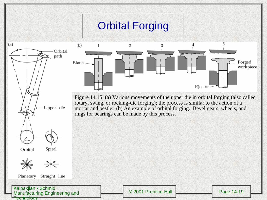
Orbital Forging
Figure 14.15 (a) Various movements of the upper die in orbital forging (also called rotary, swing, or rocking-die forging); the process is similar to the action of a mortar and pestle. (b) An example of orbital forging. Bevel gears, wheels, and rings for bearings can be made by this process.
Kalpakjian • SchmidManufacturing Engineering and Technology
© 2001 Prentice-Hall Page 14-20
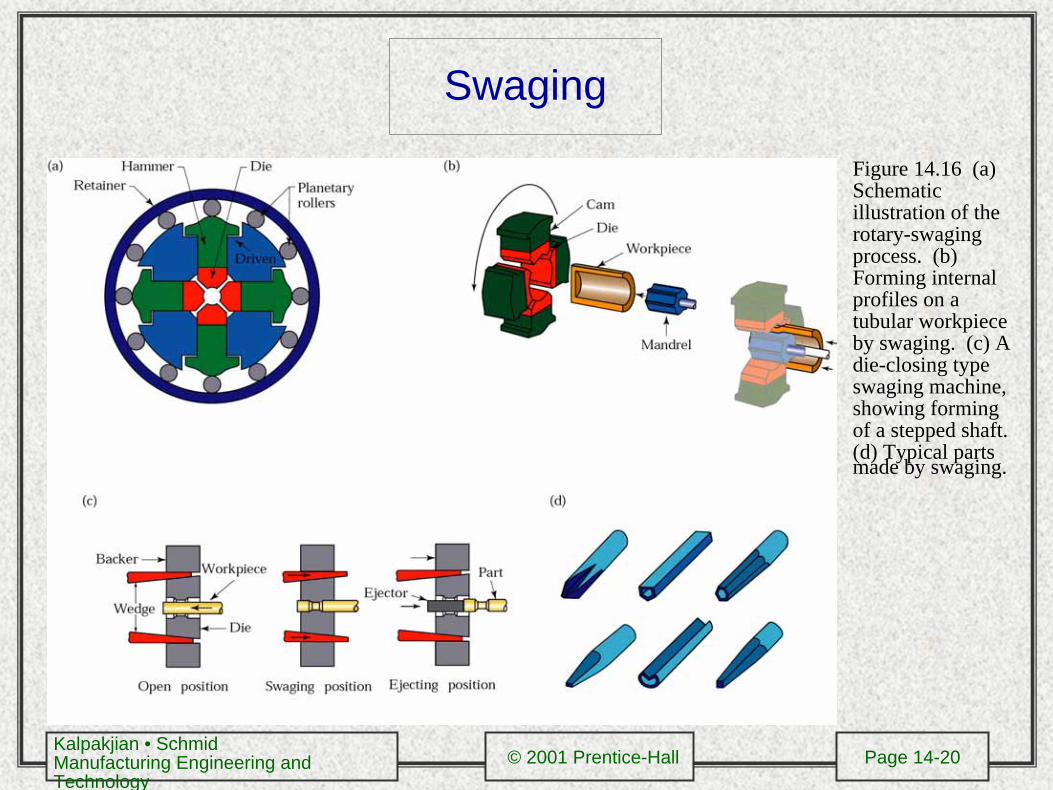
Swaging
Figure 14.16 (a) Schematic illustration of the rotary-swaging process. (b) Forming internal profiles on a tubular workpiece by swaging. (c) A die-closing type swaging machine, showing forming of a stepped shaft. (d) Typical parts made by swaging.
Kalpakjian • SchmidManufacturing Engineering and Technology
© 2001 Prentice-Hall Page 14-21
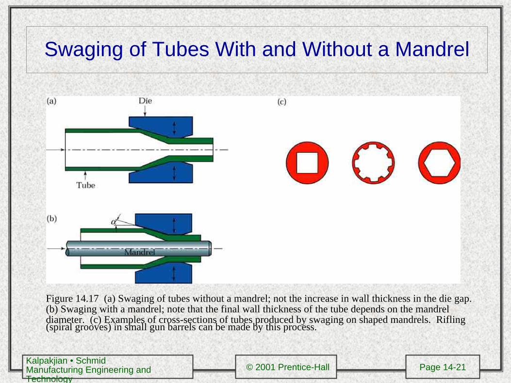
Swaging of Tubes With and Without a Mandrel
Figure 14.17 (a) Swaging of tubes without a mandrel; not the increase in wall thickness in the die gap. (b) Swaging with a mandrel; note that the final wall thickness of the tube depends on the mandrel diameter. (c) Examples of cross-sections of tubes produced by swaging on shaped mandrels. Rifling (spiral grooves) in small gun barrels can be made by this process.
Kalpakjian • SchmidManufacturing Engineering and Technology
© 2001 Prentice-Hall Page 14-22
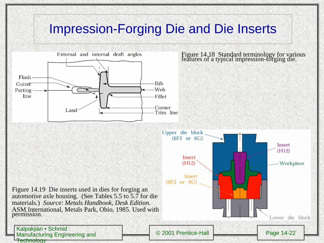
Impression-Forging Die and Die Inserts
Figure 14.18 Standard terminology for various features of a typical impression-forging die.
Figure 14.19 Die inserts used in dies for forging an automotive axle housing. (See Tables 5.5 to 5.7 for die materials.) Source: Metals Handbook, Desk Edition. ASM International, Metals Park, Ohio, 1985. Used with permission.
Kalpakjian • SchmidManufacturing Engineering and Technology
© 2001 Prentice-Hall Page 14-23
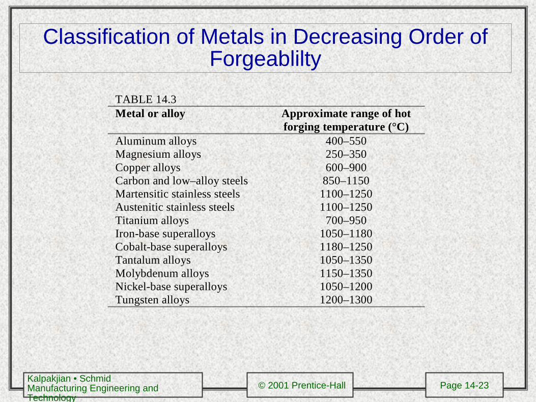
Classification of Metals in Decreasing Order of Forgeablilty
TABLE 14.3Metal or alloy Approximate range of hot
forging temperature (°C)Aluminum alloysMagnesium alloysCopper alloysCarbon and low–alloy steelsMartensitic stainless steelsAustenitic stainless steelsTitanium alloysIron-base superalloysCobalt-base superalloysTantalum alloysMolybdenum alloysNickel-base superalloysTungsten alloys
400–550250–350600–900
850–11501100–12501100–1250
700–9501050–11801180–12501050–13501150–13501050–12001200–1300
Kalpakjian • SchmidManufacturing Engineering and Technology
© 2001 Prentice-Hall Page 14-24
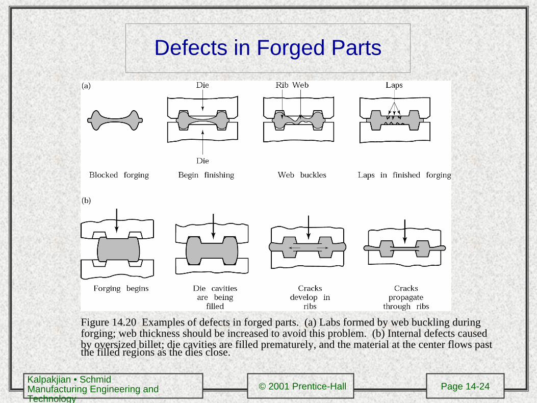
Defects in Forged Parts
Figure 14.20 Examples of defects in forged parts. (a) Labs formed by web buckling during forging; web thickness should be increased to avoid this problem. (b) Internal defects caused by oversized billet; die cavities are filled prematurely, and the material at the center flows past the filled regions as the dies close.
Kalpakjian • SchmidManufacturing Engineering and Technology
© 2001 Prentice-Hall Page 14-25
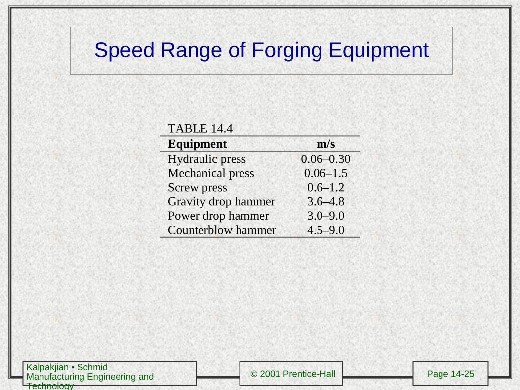
Speed Range of Forging Equipment
TABLE 14.4Equipment m/sHydraulic pressMechanical pressScrew pressGravity drop hammerPower drop hammerCounterblow hammer
0.06–0.300.06–1.50.6–1.23.6–4.83.0–9.04.5–9.0
Kalpakjian • SchmidManufacturing Engineering and Technology
© 2001 Prentice-Hall Page 14-26
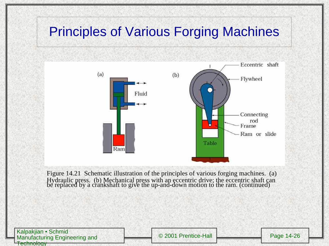
Principles of Various Forging Machines
Figure 14.21 Schematic illustration of the principles of various forging machines. (a) Hydraulic press. (b) Mechanical press with an eccentric drive; the eccentric shaft can be replaced by a crankshaft to give the up-and-down motion to the ram. (continued)
Kalpakjian • SchmidManufacturing Engineering and Technology
© 2001 Prentice-Hall Page 14-27
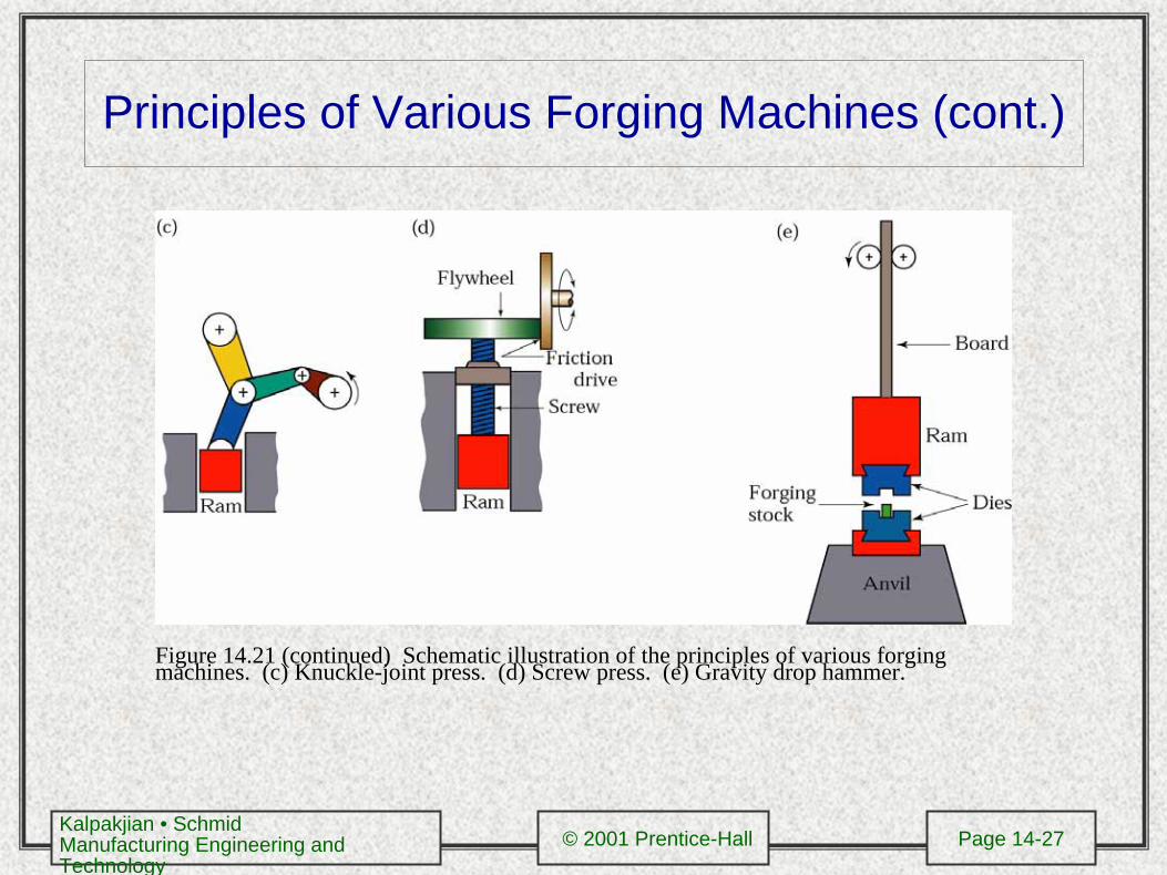
Principles of Various Forging Machines (cont.)
Figure 14.21 (continued) Schematic illustration of the principles of various forging machines. (c) Knuckle-joint press. (d) Screw press. (e) Gravity drop hammer.
Kalpakjian • SchmidManufacturing Engineering and Technology
© 2001 Prentice-Hall Page 14-28
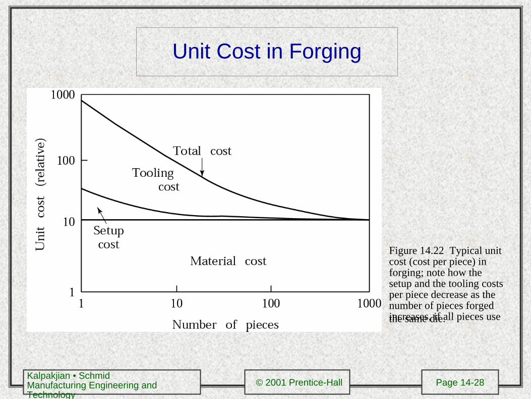
Unit Cost in Forging
Figure 14.22 Typical unit cost (cost per piece) in forging; note how the setup and the tooling costs per piece decrease as the number of pieces forged increases, if all pieces use the same die.
Kalpakjian • SchmidManufacturing Engineering and Technology
© 2001 Prentice-Hall Page 14-29
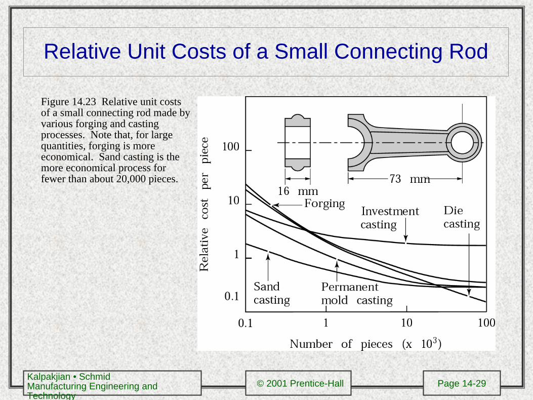
Relative Unit Costs of a Small Connecting Rod
Figure 14.23 Relative unit costs of a small connecting rod made by various forging and casting processes. Note that, for large quantities, forging is more economical. Sand casting is the more economical process for fewer than about 20,000 pieces.