Embed Size (px)
Citation preview
2017
ARM Cortex-M4 MCU and STM32F4 Discovery boarddescription
Embedded Systems Software Training Center
INSTRUCTOR INTRODUCTION
2Copyright copy 2017 DSR Corporation
Morozov Evgeniy YurievichSoftware engineer
DSR corp
evgeniymorozovdsr-corporationcom
OBJECTIVES
Learn basics about ARM Cortex-M4 background and architecture
STM32F4 DISCOVERY board functional review
Development tools for ARM Cortex-M4
Getting started with STM32F407 configuration and programming
3Copyright copy 2017 DSR Corporation
AGENDA
History and background of ARM CPUs
STM32F4 DISCOVERY board review
STM32F407VGT6 MCU functional review
Development tools for ARM programming
STM32F407 programming basics
Memory organization
Chipset frequency configuration
General Purpose InputOutput
Hardware Timers
Interrupt and exception handling
4Copyright copy 2017 DSR Corporation
2017
History and background of ARM CPUs
ARM COMPANY
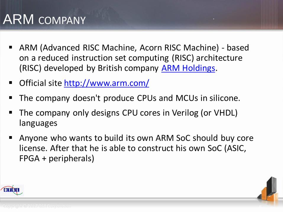
ARM (Advanced RISC Machine Acorn RISC Machine) - based on a reduced instruction set computing (RISC) architecture (RISC) developed by British company ARM Holdings
Official site httpwwwarmcom
The company doesnt produce CPUs and MCUs in silicone
The company only designs CPU cores in Verilog (or VHDL) languages
Anyone who wants to build its own ARM SoC should buy core license After that he is able to construct his own SoC (ASIC FPGA + peripherals)
6Copyright copy 2017 DSR Corporation
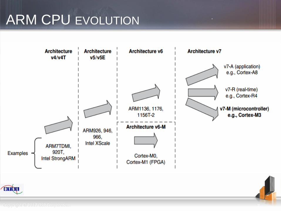
ARM CPU EVOLUTION
7Copyright copy 2017 DSR Corporation
ARM CPU EVOLUTION (PART1)
The main (well known in the embedded world) ARM old CPUs are
ARM7 - for embedded applications (MCU)
30 ndash 75 MHz up to 512 kB Flash up to 128 kB RAM
No cache no MMU 3-stage pipeline
ARM9E - for mobile applications
~ 200 - 400 MHz cache MMU DSP external Flash and RAM
ARM11ndash for high-performance applications
~ 700 MHz MMU cache 8-stage pipeline DSP FPU ext Flash and RAM
8Copyright copy 2017 DSR Corporation
ARM CPU EVOLUTION (PART 2)
After re-branding ARM named their CPUs as Cortex-ltcharactergt
ARM Cortex-M MCUs (Next generation of ARM7 and ARM9)
For embedded applications
ARM Cortex-R MCUs
For hard real-time applications
ARM Cortex-A CPUs (Next generation of ARM11)
For high-performance applications
9Copyright copy 2017 DSR Corporation
ARM CPU EVOLUTION (PART 2)
10Copyright copy 2017 DSR Corporation
2017
STM32F4 DISCOVERY KIT
STM32F4DISCOVERY
12Copyright copy 2017 DSR Corporation
ST-LINKV2Programming
tool
Reset button
User button
USBOTG
Audio Jack
STM32F407VGT6
STM32F4DISCOVERY
13Copyright copy 2017 DSR Corporation
Hardware block diagram Top layout
STM32F4DISCOVERY FEATURES STM32F407VGT6 MCU featuring 1 MB of Flash memory 192 KB of RAM
On-board ST-LINKV2 with selection mode switch
Board power supply through USB bus or from an external 5V
External application power supply 3V and 5V
LIS302DL ST MEMS motion sensor 3-axis digital output accelerometer
MP45DT02 ST MEMS audio sensor omnidirectional digital microphone
CS43L22 audio DAC with integrated class D speaker driver
Eight LEDs
LD1 (redgreen) for USB communication
LD2 (red) for 33V power on
Four user LEDs LD3 (orange) LD4 (green) LD5 (red) and LD6 (blue)
2 USB OTG LEDs LD7 (green) VBus and LD8 (red) over-current
Two pushbuttons (user and reset)
USB OTG with micro-AB connector
14Copyright copy 2017 DSR Corporation
USEFUL LINKS
15Copyright copy 2017 DSR Corporation
STM32F4DISCOVERY Product page
User manual
STM32F4DISCOVERY board firmware package including 22 examples
2017
STM32F407VGT6 MCU
ARM CORTEX M4 CORE
17Copyright copy 2017 DSR Corporation
STM32F407VGT6 BLOCKS
18Copyright copy 2017 DSR Corporation
STM32F407VGT6 CORE MAIN FEATURES
19Copyright copy 2017 DSR Corporation
ARM 32-bit Cortextrade-M4 CPU (168 MHz 1 Mbyte of Flash memory 192+4 Kbytes of SRAM including 64-Kbyte of CCM data RAM)
3times12-bit AD converters 2times12-bit DA converters General-purpose DMA 16-stream DMA controller Twelve 16-bit and two 32-bit timers with PWM or pulse counters Serial wire debug (SWD) amp JTAG interfaces Up to 140 IO ports with interrupt capability Up to 3 times I2C interfaces (SMBusPMBus) Up to 4 USARTs2 UARTs Up to 3 SPIs (42 Mbitss) 2 times CAN interfaces (20B Active) USB 20 full-speed devicehostOTG controller 10100 Ethernet MAC with dedicated DMA 8- to 14-bit parallel camera interface up to 54 Mbytess LCD parallel interface 80806800 modes
USEFUL LINKS
20Copyright copy 2017 DSR Corporation
STM32F407VG product page
Reference manual including functional and register description
Other documentation
SPL Library documentation
2017
STM32F407VGT6 MCU
POPULAR DEVELOPMENT TOOLS FOR CORTEX-M4
22Copyright copy 2017 DSR Corporation
Atmel Studio by Atmel (based on Visual Studio and GNU GCC Toolchain)
Code Composer Studio by Texas Instruments CoIDE by CooCox Eclipse as IDE with GNU Tools as compilerlinker eg aided
with GNU ARM Eclipse Plug-ins GNU Tools (aka GCC) for ARM Embedded Processors by ARM
Ltd - free GCC for bare metal IAR Embedded Workbench for ARM by IAR Keil MDK-ARM by Keil Visual Studio by Microsoft as IDE with GNU Tools as
compilerlinker - eg supported by VisualGDB
STM32F4 LIBRARIES
23Copyright copy 2017 DSR Corporation
CMSIS ndash Cortex Microcontroller Interface Standard vendor-independent hardware abstraction layer for the Cortex-M processor series and specifies debugger interfaces
SPL ndash Standard Peripheral Library for STM32 Microcontrollers Implements Hardware Abstraction Layer for STM32 peripherals Often can be downloaded with CMSIS API reference
STM32Cube - Embedded software for STM32 F4 series (HAL low level drivers USB TCPIP File system RTOS Graphic -coming with examples running on ST boards) Modern version of STM32 library from STMicroelectronics
CMSIS - CORTEX MICROCONTROLLER
SOFTWARE INTERFACE STANDARD
24Copyright copy 2017 DSR Corporation
CMSIS DESCRIPTION
25Copyright copy 2017 DSR Corporation
CMSIS-CORE API for the Cortex-M processor core and peripherals It provides at standardized interface for Cortex-M0 Cortex-M3 Cortex-M4 SC000 and SC300
CMSIS-DSP DSP Library Collection CMSIS-RTOS API Common API for Real-Time operating systems CMSIS-SVD System View Description for Peripherals Describes the
peripherals of a device in an XML file and can be used to create peripheral awareness in debuggers or header files with peripheral register and interrupt definitions
CMSIS-DAP Debug Access Port Standardized firmware for a Debug Unit that connects to the CoreSight Debug Access Port CMSIS-DAP is distributed as separate package and well suited for integration on evaluation boards This component is provided as separate download
2017
Programming STM32F407
MEMORY ORGANIZATION
27Copyright copy 2017 DSR Corporation
At startup boot pins are used to select one out of three boot options Boot from user Flash Boot from system
memory Boot from embedded
SRAM
Memory access overview 32-bit data bus 4 Gb common memory
space for flash internal ram peripherals external ram debug blocks etc
Unaligned data access Bit-band method
THE CORTEX-M3M4 REGISTERS
28Copyright copy 2017 DSR Corporation
CHIPSET FREQUENCY CONFIGURATION
29Copyright copy 2017 DSR Corporation
Three different clock sources can be used to drive the system clock (SYSCLK)
HSI oscillator clock signal is generated from an internal 16 MHz RC oscillator and can be used directly as a system clock or used as PLL input
HSE oscillator clock signal can be generated from external crystalceramic resonator or external user clock
Main PLL (PLL) clock featuring high speed system clock (up to 168 MHz) and clock for the USB OTG FS (48 MHz) the random analog generator (le48 MHz) and the SDIO (le 48 MHz)
SYSCLK configuration for STM32F4DISCOVERY board
SYSCLK (system_ stm32f4xxh) = PLL_VCO PLL_PPLL_VCO(system_ stm32f4xxh) = (HSE_VALUE or HSI_VALUE PLL_M) PLL_NHSE_VALUE (stm32f4xxh) = 8 000 000 Hz
GPIO CONFIGURATION
30Copyright copy 2017 DSR Corporation
Configuration registers GPIOx_MODER GPIOx_OTYPER GPIOx_OSPEEDR and GPIOx_PUPDR
Data registers GPIOx_IDR and GPIOx_ODRSetreset register GPIOx_BSRRLocking register GPIOx_LCKR Alternate function selection registers GPIOx_AFRH and GPIOx_AFRL
To configuring GPIO using SPL driver Include stm32f4xx_gpioh in your project Enable the GPIO AHB clock using the following function
RCC_AHB1PeriphClockCmd(RCC_AHB1Periph_GPIOx ENABLE) Configure the GPIO pin(s) using GPIO_Init() To get the level of a pin configured in input mode use
GPIO_ReadInputDataBit() To setreset the level of a pin configured in output mode use
GPIO_SetBits()GPIO_ResetBits()
STM32F407 TIMERS
31Copyright copy 2017 DSR Corporation
General-purpose timers (TIM2 to TIM5) 16-bit (TIM3 and TIM4) 32-bit (TIM2 and TIM5) up down updown auto-reload counters
General-purpose timers (TIM9 to TIM14) 16-bit auto-reload upcounter
Advanced-control timers (TIM1ampTIM8) 16-bit up down updown auto-reload counter Used for 3-phase motor control
Basic timers (TIM6ampTIM7) 16-bit auto-reload upcounter
TIMERS CONFIGURATION
32Copyright copy 2017 DSR Corporation
Timer clock configurationHCLK = SYSCLKPCLK1 = HCLK 4TIM_CLK = 2PCLK1 = SYSCLK 2
To configuring Timers using SPL driverbull Include stm32f4xx_timhbull Enable TIM clock using RCC_APBxPeriphClockCmd(RCC_APBxPeriph_TIMx
ENABLE) functionbull Fill the TIM_TimeBaseInitStruct with the desired parametersbull Call TIM_TimeBaseInit(TIMx ampTIM_TimeBaseInitStruct) to configure the Time
Base unit with the corresponding configurationbull Enable the NVIC if you need to generate the update interruptbull Enable the corresponding interrupt using the function TIM_ITConfig(TIMx
TIM_IT_Update)bull Call the TIM_Cmd(ENABLE) function to enable the TIM counter
INTERRUPTS AND EVENTS
33Copyright copy 2017 DSR Corporation
Nested vectored interrupt controller (NVIC)The nested vector interrupt controller NVIC includes the following features
82 maskable interrupt channels for STM32F407xx 16 programmable priority levels (4 bits of interrupt priority are used) low-latency exception and interrupt handling power management control implementation of system control registers
The NVIC and the processor core interface are closely coupled which enables low latency interrupt processing and efficient processing of late arriving interrupts
External interruptevent controller (EXTI)The external interruptevent controller consists of up to 23 edge detectors for generating eventinterrupt requests Each input line can be independently configured to select the type (interrupt or event) and the corresponding trigger event (rising or falling or both) Each line can also masked independently A pending register maintains the status line of the interrupt requests
CMSIS NVIC DRIVER
34Copyright copy 2017 DSR Corporation
Definitions mischInterrupt table startup_stm32F4xxxs
Define your interrupt handler Configure the NVIC Priority Grouping using NVIC_PriorityGroupConfig() Enable and Configure the priority of the selected IRQ Channels using NVIC_Init()
ExampleNVIC_InitTypeDef nvic_structnvic_structNVIC_IRQChannel = TIM2_IRQnnvic_structNVIC_IRQChannelPreemptionPriority = 0nvic_structNVIC_IRQChannelSubPriority = 1nvic_structNVIC_IRQChannelCmd = ENABLENVIC_Init(ampnvic_struct)
35Copyright copy 2017 DSR Corporation
Is there any questions
2017
Thank You
INSTRUCTOR INTRODUCTION
2Copyright copy 2017 DSR Corporation
Morozov Evgeniy YurievichSoftware engineer
DSR corp
evgeniymorozovdsr-corporationcom
OBJECTIVES
Learn basics about ARM Cortex-M4 background and architecture
STM32F4 DISCOVERY board functional review
Development tools for ARM Cortex-M4
Getting started with STM32F407 configuration and programming
3Copyright copy 2017 DSR Corporation
AGENDA
History and background of ARM CPUs
STM32F4 DISCOVERY board review
STM32F407VGT6 MCU functional review
Development tools for ARM programming
STM32F407 programming basics
Memory organization
Chipset frequency configuration
General Purpose InputOutput
Hardware Timers
Interrupt and exception handling
4Copyright copy 2017 DSR Corporation
2017
History and background of ARM CPUs
ARM COMPANY
ARM (Advanced RISC Machine Acorn RISC Machine) - based on a reduced instruction set computing (RISC) architecture (RISC) developed by British company ARM Holdings
Official site httpwwwarmcom
The company doesnt produce CPUs and MCUs in silicone
The company only designs CPU cores in Verilog (or VHDL) languages
Anyone who wants to build its own ARM SoC should buy core license After that he is able to construct his own SoC (ASIC FPGA + peripherals)
6Copyright copy 2017 DSR Corporation
ARM CPU EVOLUTION
7Copyright copy 2017 DSR Corporation
ARM CPU EVOLUTION (PART1)
The main (well known in the embedded world) ARM old CPUs are
ARM7 - for embedded applications (MCU)
30 ndash 75 MHz up to 512 kB Flash up to 128 kB RAM
No cache no MMU 3-stage pipeline
ARM9E - for mobile applications
~ 200 - 400 MHz cache MMU DSP external Flash and RAM
ARM11ndash for high-performance applications
~ 700 MHz MMU cache 8-stage pipeline DSP FPU ext Flash and RAM
8Copyright copy 2017 DSR Corporation
ARM CPU EVOLUTION (PART 2)
After re-branding ARM named their CPUs as Cortex-ltcharactergt
ARM Cortex-M MCUs (Next generation of ARM7 and ARM9)
For embedded applications
ARM Cortex-R MCUs
For hard real-time applications
ARM Cortex-A CPUs (Next generation of ARM11)
For high-performance applications
9Copyright copy 2017 DSR Corporation
ARM CPU EVOLUTION (PART 2)
10Copyright copy 2017 DSR Corporation
2017
STM32F4 DISCOVERY KIT
STM32F4DISCOVERY
12Copyright copy 2017 DSR Corporation
ST-LINKV2Programming
tool
Reset button
User button
USBOTG
Audio Jack
STM32F407VGT6
STM32F4DISCOVERY
13Copyright copy 2017 DSR Corporation
Hardware block diagram Top layout
STM32F4DISCOVERY FEATURES STM32F407VGT6 MCU featuring 1 MB of Flash memory 192 KB of RAM
On-board ST-LINKV2 with selection mode switch
Board power supply through USB bus or from an external 5V
External application power supply 3V and 5V
LIS302DL ST MEMS motion sensor 3-axis digital output accelerometer
MP45DT02 ST MEMS audio sensor omnidirectional digital microphone
CS43L22 audio DAC with integrated class D speaker driver
Eight LEDs
LD1 (redgreen) for USB communication
LD2 (red) for 33V power on
Four user LEDs LD3 (orange) LD4 (green) LD5 (red) and LD6 (blue)
2 USB OTG LEDs LD7 (green) VBus and LD8 (red) over-current
Two pushbuttons (user and reset)
USB OTG with micro-AB connector
14Copyright copy 2017 DSR Corporation
USEFUL LINKS
15Copyright copy 2017 DSR Corporation
STM32F4DISCOVERY Product page
User manual
STM32F4DISCOVERY board firmware package including 22 examples
2017
STM32F407VGT6 MCU
ARM CORTEX M4 CORE
17Copyright copy 2017 DSR Corporation
STM32F407VGT6 BLOCKS
18Copyright copy 2017 DSR Corporation
STM32F407VGT6 CORE MAIN FEATURES
19Copyright copy 2017 DSR Corporation
ARM 32-bit Cortextrade-M4 CPU (168 MHz 1 Mbyte of Flash memory 192+4 Kbytes of SRAM including 64-Kbyte of CCM data RAM)
3times12-bit AD converters 2times12-bit DA converters General-purpose DMA 16-stream DMA controller Twelve 16-bit and two 32-bit timers with PWM or pulse counters Serial wire debug (SWD) amp JTAG interfaces Up to 140 IO ports with interrupt capability Up to 3 times I2C interfaces (SMBusPMBus) Up to 4 USARTs2 UARTs Up to 3 SPIs (42 Mbitss) 2 times CAN interfaces (20B Active) USB 20 full-speed devicehostOTG controller 10100 Ethernet MAC with dedicated DMA 8- to 14-bit parallel camera interface up to 54 Mbytess LCD parallel interface 80806800 modes
USEFUL LINKS
20Copyright copy 2017 DSR Corporation
STM32F407VG product page
Reference manual including functional and register description
Other documentation
SPL Library documentation
2017
STM32F407VGT6 MCU
POPULAR DEVELOPMENT TOOLS FOR CORTEX-M4
22Copyright copy 2017 DSR Corporation
Atmel Studio by Atmel (based on Visual Studio and GNU GCC Toolchain)
Code Composer Studio by Texas Instruments CoIDE by CooCox Eclipse as IDE with GNU Tools as compilerlinker eg aided
with GNU ARM Eclipse Plug-ins GNU Tools (aka GCC) for ARM Embedded Processors by ARM
Ltd - free GCC for bare metal IAR Embedded Workbench for ARM by IAR Keil MDK-ARM by Keil Visual Studio by Microsoft as IDE with GNU Tools as
compilerlinker - eg supported by VisualGDB
STM32F4 LIBRARIES
23Copyright copy 2017 DSR Corporation
CMSIS ndash Cortex Microcontroller Interface Standard vendor-independent hardware abstraction layer for the Cortex-M processor series and specifies debugger interfaces
SPL ndash Standard Peripheral Library for STM32 Microcontrollers Implements Hardware Abstraction Layer for STM32 peripherals Often can be downloaded with CMSIS API reference
STM32Cube - Embedded software for STM32 F4 series (HAL low level drivers USB TCPIP File system RTOS Graphic -coming with examples running on ST boards) Modern version of STM32 library from STMicroelectronics
CMSIS - CORTEX MICROCONTROLLER
SOFTWARE INTERFACE STANDARD
24Copyright copy 2017 DSR Corporation
CMSIS DESCRIPTION
25Copyright copy 2017 DSR Corporation
CMSIS-CORE API for the Cortex-M processor core and peripherals It provides at standardized interface for Cortex-M0 Cortex-M3 Cortex-M4 SC000 and SC300
CMSIS-DSP DSP Library Collection CMSIS-RTOS API Common API for Real-Time operating systems CMSIS-SVD System View Description for Peripherals Describes the
peripherals of a device in an XML file and can be used to create peripheral awareness in debuggers or header files with peripheral register and interrupt definitions
CMSIS-DAP Debug Access Port Standardized firmware for a Debug Unit that connects to the CoreSight Debug Access Port CMSIS-DAP is distributed as separate package and well suited for integration on evaluation boards This component is provided as separate download
2017
Programming STM32F407
MEMORY ORGANIZATION
27Copyright copy 2017 DSR Corporation
At startup boot pins are used to select one out of three boot options Boot from user Flash Boot from system
memory Boot from embedded
SRAM
Memory access overview 32-bit data bus 4 Gb common memory
space for flash internal ram peripherals external ram debug blocks etc
Unaligned data access Bit-band method
THE CORTEX-M3M4 REGISTERS
28Copyright copy 2017 DSR Corporation
CHIPSET FREQUENCY CONFIGURATION
29Copyright copy 2017 DSR Corporation
Three different clock sources can be used to drive the system clock (SYSCLK)
HSI oscillator clock signal is generated from an internal 16 MHz RC oscillator and can be used directly as a system clock or used as PLL input
HSE oscillator clock signal can be generated from external crystalceramic resonator or external user clock
Main PLL (PLL) clock featuring high speed system clock (up to 168 MHz) and clock for the USB OTG FS (48 MHz) the random analog generator (le48 MHz) and the SDIO (le 48 MHz)
SYSCLK configuration for STM32F4DISCOVERY board
SYSCLK (system_ stm32f4xxh) = PLL_VCO PLL_PPLL_VCO(system_ stm32f4xxh) = (HSE_VALUE or HSI_VALUE PLL_M) PLL_NHSE_VALUE (stm32f4xxh) = 8 000 000 Hz
GPIO CONFIGURATION
30Copyright copy 2017 DSR Corporation
Configuration registers GPIOx_MODER GPIOx_OTYPER GPIOx_OSPEEDR and GPIOx_PUPDR
Data registers GPIOx_IDR and GPIOx_ODRSetreset register GPIOx_BSRRLocking register GPIOx_LCKR Alternate function selection registers GPIOx_AFRH and GPIOx_AFRL
To configuring GPIO using SPL driver Include stm32f4xx_gpioh in your project Enable the GPIO AHB clock using the following function
RCC_AHB1PeriphClockCmd(RCC_AHB1Periph_GPIOx ENABLE) Configure the GPIO pin(s) using GPIO_Init() To get the level of a pin configured in input mode use
GPIO_ReadInputDataBit() To setreset the level of a pin configured in output mode use
GPIO_SetBits()GPIO_ResetBits()
STM32F407 TIMERS
31Copyright copy 2017 DSR Corporation
General-purpose timers (TIM2 to TIM5) 16-bit (TIM3 and TIM4) 32-bit (TIM2 and TIM5) up down updown auto-reload counters
General-purpose timers (TIM9 to TIM14) 16-bit auto-reload upcounter
Advanced-control timers (TIM1ampTIM8) 16-bit up down updown auto-reload counter Used for 3-phase motor control
Basic timers (TIM6ampTIM7) 16-bit auto-reload upcounter
TIMERS CONFIGURATION
32Copyright copy 2017 DSR Corporation
Timer clock configurationHCLK = SYSCLKPCLK1 = HCLK 4TIM_CLK = 2PCLK1 = SYSCLK 2
To configuring Timers using SPL driverbull Include stm32f4xx_timhbull Enable TIM clock using RCC_APBxPeriphClockCmd(RCC_APBxPeriph_TIMx
ENABLE) functionbull Fill the TIM_TimeBaseInitStruct with the desired parametersbull Call TIM_TimeBaseInit(TIMx ampTIM_TimeBaseInitStruct) to configure the Time
Base unit with the corresponding configurationbull Enable the NVIC if you need to generate the update interruptbull Enable the corresponding interrupt using the function TIM_ITConfig(TIMx
TIM_IT_Update)bull Call the TIM_Cmd(ENABLE) function to enable the TIM counter
INTERRUPTS AND EVENTS
33Copyright copy 2017 DSR Corporation
Nested vectored interrupt controller (NVIC)The nested vector interrupt controller NVIC includes the following features
82 maskable interrupt channels for STM32F407xx 16 programmable priority levels (4 bits of interrupt priority are used) low-latency exception and interrupt handling power management control implementation of system control registers
The NVIC and the processor core interface are closely coupled which enables low latency interrupt processing and efficient processing of late arriving interrupts
External interruptevent controller (EXTI)The external interruptevent controller consists of up to 23 edge detectors for generating eventinterrupt requests Each input line can be independently configured to select the type (interrupt or event) and the corresponding trigger event (rising or falling or both) Each line can also masked independently A pending register maintains the status line of the interrupt requests
CMSIS NVIC DRIVER
34Copyright copy 2017 DSR Corporation
Definitions mischInterrupt table startup_stm32F4xxxs
Define your interrupt handler Configure the NVIC Priority Grouping using NVIC_PriorityGroupConfig() Enable and Configure the priority of the selected IRQ Channels using NVIC_Init()
ExampleNVIC_InitTypeDef nvic_structnvic_structNVIC_IRQChannel = TIM2_IRQnnvic_structNVIC_IRQChannelPreemptionPriority = 0nvic_structNVIC_IRQChannelSubPriority = 1nvic_structNVIC_IRQChannelCmd = ENABLENVIC_Init(ampnvic_struct)
35Copyright copy 2017 DSR Corporation
Is there any questions
2017
Thank You
2017
History and background of ARM CPUs
ARM COMPANY
ARM (Advanced RISC Machine Acorn RISC Machine) - based on a reduced instruction set computing (RISC) architecture (RISC) developed by British company ARM Holdings
Official site httpwwwarmcom
The company doesnt produce CPUs and MCUs in silicone
The company only designs CPU cores in Verilog (or VHDL) languages
Anyone who wants to build its own ARM SoC should buy core license After that he is able to construct his own SoC (ASIC FPGA + peripherals)
6Copyright copy 2017 DSR Corporation
ARM CPU EVOLUTION
7Copyright copy 2017 DSR Corporation
ARM CPU EVOLUTION (PART1)
The main (well known in the embedded world) ARM old CPUs are
ARM7 - for embedded applications (MCU)
30 ndash 75 MHz up to 512 kB Flash up to 128 kB RAM
No cache no MMU 3-stage pipeline
ARM9E - for mobile applications
~ 200 - 400 MHz cache MMU DSP external Flash and RAM
ARM11ndash for high-performance applications
~ 700 MHz MMU cache 8-stage pipeline DSP FPU ext Flash and RAM
8Copyright copy 2017 DSR Corporation
ARM CPU EVOLUTION (PART 2)
After re-branding ARM named their CPUs as Cortex-ltcharactergt
ARM Cortex-M MCUs (Next generation of ARM7 and ARM9)
For embedded applications
ARM Cortex-R MCUs
For hard real-time applications
ARM Cortex-A CPUs (Next generation of ARM11)
For high-performance applications
9Copyright copy 2017 DSR Corporation
ARM CPU EVOLUTION (PART 2)
10Copyright copy 2017 DSR Corporation
2017
STM32F4 DISCOVERY KIT
STM32F4DISCOVERY
12Copyright copy 2017 DSR Corporation
ST-LINKV2Programming
tool
Reset button
User button
USBOTG
Audio Jack
STM32F407VGT6
STM32F4DISCOVERY
13Copyright copy 2017 DSR Corporation
Hardware block diagram Top layout
STM32F4DISCOVERY FEATURES STM32F407VGT6 MCU featuring 1 MB of Flash memory 192 KB of RAM
On-board ST-LINKV2 with selection mode switch
Board power supply through USB bus or from an external 5V
External application power supply 3V and 5V
LIS302DL ST MEMS motion sensor 3-axis digital output accelerometer
MP45DT02 ST MEMS audio sensor omnidirectional digital microphone
CS43L22 audio DAC with integrated class D speaker driver
Eight LEDs
LD1 (redgreen) for USB communication
LD2 (red) for 33V power on
Four user LEDs LD3 (orange) LD4 (green) LD5 (red) and LD6 (blue)
2 USB OTG LEDs LD7 (green) VBus and LD8 (red) over-current
Two pushbuttons (user and reset)
USB OTG with micro-AB connector
14Copyright copy 2017 DSR Corporation
USEFUL LINKS
15Copyright copy 2017 DSR Corporation
STM32F4DISCOVERY Product page
User manual
STM32F4DISCOVERY board firmware package including 22 examples
2017
STM32F407VGT6 MCU
ARM CORTEX M4 CORE
17Copyright copy 2017 DSR Corporation
STM32F407VGT6 BLOCKS
18Copyright copy 2017 DSR Corporation
STM32F407VGT6 CORE MAIN FEATURES
19Copyright copy 2017 DSR Corporation
ARM 32-bit Cortextrade-M4 CPU (168 MHz 1 Mbyte of Flash memory 192+4 Kbytes of SRAM including 64-Kbyte of CCM data RAM)
3times12-bit AD converters 2times12-bit DA converters General-purpose DMA 16-stream DMA controller Twelve 16-bit and two 32-bit timers with PWM or pulse counters Serial wire debug (SWD) amp JTAG interfaces Up to 140 IO ports with interrupt capability Up to 3 times I2C interfaces (SMBusPMBus) Up to 4 USARTs2 UARTs Up to 3 SPIs (42 Mbitss) 2 times CAN interfaces (20B Active) USB 20 full-speed devicehostOTG controller 10100 Ethernet MAC with dedicated DMA 8- to 14-bit parallel camera interface up to 54 Mbytess LCD parallel interface 80806800 modes
USEFUL LINKS
20Copyright copy 2017 DSR Corporation
STM32F407VG product page
Reference manual including functional and register description
Other documentation
SPL Library documentation
2017
STM32F407VGT6 MCU
POPULAR DEVELOPMENT TOOLS FOR CORTEX-M4
22Copyright copy 2017 DSR Corporation
Atmel Studio by Atmel (based on Visual Studio and GNU GCC Toolchain)
Code Composer Studio by Texas Instruments CoIDE by CooCox Eclipse as IDE with GNU Tools as compilerlinker eg aided
with GNU ARM Eclipse Plug-ins GNU Tools (aka GCC) for ARM Embedded Processors by ARM
Ltd - free GCC for bare metal IAR Embedded Workbench for ARM by IAR Keil MDK-ARM by Keil Visual Studio by Microsoft as IDE with GNU Tools as
compilerlinker - eg supported by VisualGDB
STM32F4 LIBRARIES
23Copyright copy 2017 DSR Corporation
CMSIS ndash Cortex Microcontroller Interface Standard vendor-independent hardware abstraction layer for the Cortex-M processor series and specifies debugger interfaces
SPL ndash Standard Peripheral Library for STM32 Microcontrollers Implements Hardware Abstraction Layer for STM32 peripherals Often can be downloaded with CMSIS API reference
STM32Cube - Embedded software for STM32 F4 series (HAL low level drivers USB TCPIP File system RTOS Graphic -coming with examples running on ST boards) Modern version of STM32 library from STMicroelectronics
CMSIS - CORTEX MICROCONTROLLER
SOFTWARE INTERFACE STANDARD
24Copyright copy 2017 DSR Corporation
CMSIS DESCRIPTION
25Copyright copy 2017 DSR Corporation
CMSIS-CORE API for the Cortex-M processor core and peripherals It provides at standardized interface for Cortex-M0 Cortex-M3 Cortex-M4 SC000 and SC300
CMSIS-DSP DSP Library Collection CMSIS-RTOS API Common API for Real-Time operating systems CMSIS-SVD System View Description for Peripherals Describes the
peripherals of a device in an XML file and can be used to create peripheral awareness in debuggers or header files with peripheral register and interrupt definitions
CMSIS-DAP Debug Access Port Standardized firmware for a Debug Unit that connects to the CoreSight Debug Access Port CMSIS-DAP is distributed as separate package and well suited for integration on evaluation boards This component is provided as separate download
2017
Programming STM32F407
MEMORY ORGANIZATION
27Copyright copy 2017 DSR Corporation
At startup boot pins are used to select one out of three boot options Boot from user Flash Boot from system
memory Boot from embedded
SRAM
Memory access overview 32-bit data bus 4 Gb common memory
space for flash internal ram peripherals external ram debug blocks etc
Unaligned data access Bit-band method
THE CORTEX-M3M4 REGISTERS
28Copyright copy 2017 DSR Corporation
CHIPSET FREQUENCY CONFIGURATION
29Copyright copy 2017 DSR Corporation
Three different clock sources can be used to drive the system clock (SYSCLK)
HSI oscillator clock signal is generated from an internal 16 MHz RC oscillator and can be used directly as a system clock or used as PLL input
HSE oscillator clock signal can be generated from external crystalceramic resonator or external user clock
Main PLL (PLL) clock featuring high speed system clock (up to 168 MHz) and clock for the USB OTG FS (48 MHz) the random analog generator (le48 MHz) and the SDIO (le 48 MHz)
SYSCLK configuration for STM32F4DISCOVERY board
SYSCLK (system_ stm32f4xxh) = PLL_VCO PLL_PPLL_VCO(system_ stm32f4xxh) = (HSE_VALUE or HSI_VALUE PLL_M) PLL_NHSE_VALUE (stm32f4xxh) = 8 000 000 Hz
GPIO CONFIGURATION
30Copyright copy 2017 DSR Corporation
Configuration registers GPIOx_MODER GPIOx_OTYPER GPIOx_OSPEEDR and GPIOx_PUPDR
Data registers GPIOx_IDR and GPIOx_ODRSetreset register GPIOx_BSRRLocking register GPIOx_LCKR Alternate function selection registers GPIOx_AFRH and GPIOx_AFRL
To configuring GPIO using SPL driver Include stm32f4xx_gpioh in your project Enable the GPIO AHB clock using the following function
RCC_AHB1PeriphClockCmd(RCC_AHB1Periph_GPIOx ENABLE) Configure the GPIO pin(s) using GPIO_Init() To get the level of a pin configured in input mode use
GPIO_ReadInputDataBit() To setreset the level of a pin configured in output mode use
GPIO_SetBits()GPIO_ResetBits()
STM32F407 TIMERS
31Copyright copy 2017 DSR Corporation
General-purpose timers (TIM2 to TIM5) 16-bit (TIM3 and TIM4) 32-bit (TIM2 and TIM5) up down updown auto-reload counters
General-purpose timers (TIM9 to TIM14) 16-bit auto-reload upcounter
Advanced-control timers (TIM1ampTIM8) 16-bit up down updown auto-reload counter Used for 3-phase motor control
Basic timers (TIM6ampTIM7) 16-bit auto-reload upcounter
TIMERS CONFIGURATION
32Copyright copy 2017 DSR Corporation
Timer clock configurationHCLK = SYSCLKPCLK1 = HCLK 4TIM_CLK = 2PCLK1 = SYSCLK 2
To configuring Timers using SPL driverbull Include stm32f4xx_timhbull Enable TIM clock using RCC_APBxPeriphClockCmd(RCC_APBxPeriph_TIMx
ENABLE) functionbull Fill the TIM_TimeBaseInitStruct with the desired parametersbull Call TIM_TimeBaseInit(TIMx ampTIM_TimeBaseInitStruct) to configure the Time
Base unit with the corresponding configurationbull Enable the NVIC if you need to generate the update interruptbull Enable the corresponding interrupt using the function TIM_ITConfig(TIMx
TIM_IT_Update)bull Call the TIM_Cmd(ENABLE) function to enable the TIM counter
INTERRUPTS AND EVENTS
33Copyright copy 2017 DSR Corporation
Nested vectored interrupt controller (NVIC)The nested vector interrupt controller NVIC includes the following features
82 maskable interrupt channels for STM32F407xx 16 programmable priority levels (4 bits of interrupt priority are used) low-latency exception and interrupt handling power management control implementation of system control registers
The NVIC and the processor core interface are closely coupled which enables low latency interrupt processing and efficient processing of late arriving interrupts
External interruptevent controller (EXTI)The external interruptevent controller consists of up to 23 edge detectors for generating eventinterrupt requests Each input line can be independently configured to select the type (interrupt or event) and the corresponding trigger event (rising or falling or both) Each line can also masked independently A pending register maintains the status line of the interrupt requests
CMSIS NVIC DRIVER
34Copyright copy 2017 DSR Corporation
Definitions mischInterrupt table startup_stm32F4xxxs
Define your interrupt handler Configure the NVIC Priority Grouping using NVIC_PriorityGroupConfig() Enable and Configure the priority of the selected IRQ Channels using NVIC_Init()
ExampleNVIC_InitTypeDef nvic_structnvic_structNVIC_IRQChannel = TIM2_IRQnnvic_structNVIC_IRQChannelPreemptionPriority = 0nvic_structNVIC_IRQChannelSubPriority = 1nvic_structNVIC_IRQChannelCmd = ENABLENVIC_Init(ampnvic_struct)
35Copyright copy 2017 DSR Corporation
Is there any questions
2017
Thank You
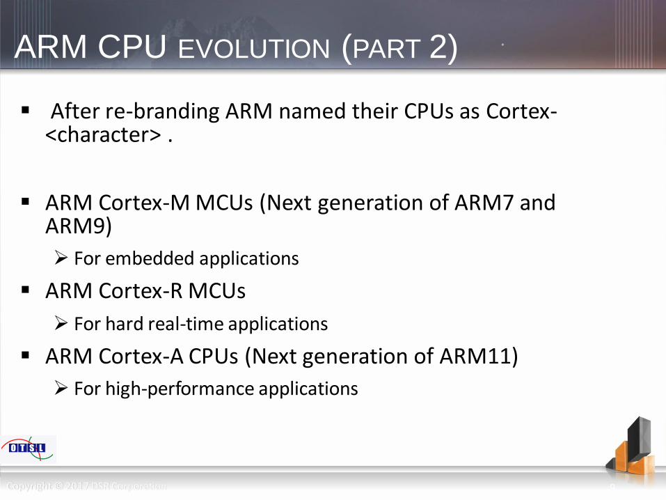
ARM CPU EVOLUTION (PART 2)
After re-branding ARM named their CPUs as Cortex-ltcharactergt
ARM Cortex-M MCUs (Next generation of ARM7 and ARM9)
For embedded applications
ARM Cortex-R MCUs
For hard real-time applications
ARM Cortex-A CPUs (Next generation of ARM11)
For high-performance applications
9Copyright copy 2017 DSR Corporation
ARM CPU EVOLUTION (PART 2)
10Copyright copy 2017 DSR Corporation
2017
STM32F4 DISCOVERY KIT
STM32F4DISCOVERY
12Copyright copy 2017 DSR Corporation
ST-LINKV2Programming
tool
Reset button
User button
USBOTG
Audio Jack
STM32F407VGT6
STM32F4DISCOVERY
13Copyright copy 2017 DSR Corporation
Hardware block diagram Top layout
STM32F4DISCOVERY FEATURES STM32F407VGT6 MCU featuring 1 MB of Flash memory 192 KB of RAM
On-board ST-LINKV2 with selection mode switch
Board power supply through USB bus or from an external 5V
External application power supply 3V and 5V
LIS302DL ST MEMS motion sensor 3-axis digital output accelerometer
MP45DT02 ST MEMS audio sensor omnidirectional digital microphone
CS43L22 audio DAC with integrated class D speaker driver
Eight LEDs
LD1 (redgreen) for USB communication
LD2 (red) for 33V power on
Four user LEDs LD3 (orange) LD4 (green) LD5 (red) and LD6 (blue)
2 USB OTG LEDs LD7 (green) VBus and LD8 (red) over-current
Two pushbuttons (user and reset)
USB OTG with micro-AB connector
14Copyright copy 2017 DSR Corporation
USEFUL LINKS
15Copyright copy 2017 DSR Corporation
STM32F4DISCOVERY Product page
User manual
STM32F4DISCOVERY board firmware package including 22 examples
2017
STM32F407VGT6 MCU
ARM CORTEX M4 CORE
17Copyright copy 2017 DSR Corporation
STM32F407VGT6 BLOCKS
18Copyright copy 2017 DSR Corporation
STM32F407VGT6 CORE MAIN FEATURES
19Copyright copy 2017 DSR Corporation
ARM 32-bit Cortextrade-M4 CPU (168 MHz 1 Mbyte of Flash memory 192+4 Kbytes of SRAM including 64-Kbyte of CCM data RAM)
3times12-bit AD converters 2times12-bit DA converters General-purpose DMA 16-stream DMA controller Twelve 16-bit and two 32-bit timers with PWM or pulse counters Serial wire debug (SWD) amp JTAG interfaces Up to 140 IO ports with interrupt capability Up to 3 times I2C interfaces (SMBusPMBus) Up to 4 USARTs2 UARTs Up to 3 SPIs (42 Mbitss) 2 times CAN interfaces (20B Active) USB 20 full-speed devicehostOTG controller 10100 Ethernet MAC with dedicated DMA 8- to 14-bit parallel camera interface up to 54 Mbytess LCD parallel interface 80806800 modes
USEFUL LINKS
20Copyright copy 2017 DSR Corporation
STM32F407VG product page
Reference manual including functional and register description
Other documentation
SPL Library documentation
2017
STM32F407VGT6 MCU
POPULAR DEVELOPMENT TOOLS FOR CORTEX-M4
22Copyright copy 2017 DSR Corporation
Atmel Studio by Atmel (based on Visual Studio and GNU GCC Toolchain)
Code Composer Studio by Texas Instruments CoIDE by CooCox Eclipse as IDE with GNU Tools as compilerlinker eg aided
with GNU ARM Eclipse Plug-ins GNU Tools (aka GCC) for ARM Embedded Processors by ARM
Ltd - free GCC for bare metal IAR Embedded Workbench for ARM by IAR Keil MDK-ARM by Keil Visual Studio by Microsoft as IDE with GNU Tools as
compilerlinker - eg supported by VisualGDB
STM32F4 LIBRARIES
23Copyright copy 2017 DSR Corporation
CMSIS ndash Cortex Microcontroller Interface Standard vendor-independent hardware abstraction layer for the Cortex-M processor series and specifies debugger interfaces
SPL ndash Standard Peripheral Library for STM32 Microcontrollers Implements Hardware Abstraction Layer for STM32 peripherals Often can be downloaded with CMSIS API reference
STM32Cube - Embedded software for STM32 F4 series (HAL low level drivers USB TCPIP File system RTOS Graphic -coming with examples running on ST boards) Modern version of STM32 library from STMicroelectronics
CMSIS - CORTEX MICROCONTROLLER
SOFTWARE INTERFACE STANDARD
24Copyright copy 2017 DSR Corporation
CMSIS DESCRIPTION
25Copyright copy 2017 DSR Corporation
CMSIS-CORE API for the Cortex-M processor core and peripherals It provides at standardized interface for Cortex-M0 Cortex-M3 Cortex-M4 SC000 and SC300
CMSIS-DSP DSP Library Collection CMSIS-RTOS API Common API for Real-Time operating systems CMSIS-SVD System View Description for Peripherals Describes the
peripherals of a device in an XML file and can be used to create peripheral awareness in debuggers or header files with peripheral register and interrupt definitions
CMSIS-DAP Debug Access Port Standardized firmware for a Debug Unit that connects to the CoreSight Debug Access Port CMSIS-DAP is distributed as separate package and well suited for integration on evaluation boards This component is provided as separate download
2017
Programming STM32F407
MEMORY ORGANIZATION
27Copyright copy 2017 DSR Corporation
At startup boot pins are used to select one out of three boot options Boot from user Flash Boot from system
memory Boot from embedded
SRAM
Memory access overview 32-bit data bus 4 Gb common memory
space for flash internal ram peripherals external ram debug blocks etc
Unaligned data access Bit-band method
THE CORTEX-M3M4 REGISTERS
28Copyright copy 2017 DSR Corporation
CHIPSET FREQUENCY CONFIGURATION
29Copyright copy 2017 DSR Corporation
Three different clock sources can be used to drive the system clock (SYSCLK)
HSI oscillator clock signal is generated from an internal 16 MHz RC oscillator and can be used directly as a system clock or used as PLL input
HSE oscillator clock signal can be generated from external crystalceramic resonator or external user clock
Main PLL (PLL) clock featuring high speed system clock (up to 168 MHz) and clock for the USB OTG FS (48 MHz) the random analog generator (le48 MHz) and the SDIO (le 48 MHz)
SYSCLK configuration for STM32F4DISCOVERY board
SYSCLK (system_ stm32f4xxh) = PLL_VCO PLL_PPLL_VCO(system_ stm32f4xxh) = (HSE_VALUE or HSI_VALUE PLL_M) PLL_NHSE_VALUE (stm32f4xxh) = 8 000 000 Hz
GPIO CONFIGURATION
30Copyright copy 2017 DSR Corporation
Configuration registers GPIOx_MODER GPIOx_OTYPER GPIOx_OSPEEDR and GPIOx_PUPDR
Data registers GPIOx_IDR and GPIOx_ODRSetreset register GPIOx_BSRRLocking register GPIOx_LCKR Alternate function selection registers GPIOx_AFRH and GPIOx_AFRL
To configuring GPIO using SPL driver Include stm32f4xx_gpioh in your project Enable the GPIO AHB clock using the following function
RCC_AHB1PeriphClockCmd(RCC_AHB1Periph_GPIOx ENABLE) Configure the GPIO pin(s) using GPIO_Init() To get the level of a pin configured in input mode use
GPIO_ReadInputDataBit() To setreset the level of a pin configured in output mode use
GPIO_SetBits()GPIO_ResetBits()
STM32F407 TIMERS
31Copyright copy 2017 DSR Corporation
General-purpose timers (TIM2 to TIM5) 16-bit (TIM3 and TIM4) 32-bit (TIM2 and TIM5) up down updown auto-reload counters
General-purpose timers (TIM9 to TIM14) 16-bit auto-reload upcounter
Advanced-control timers (TIM1ampTIM8) 16-bit up down updown auto-reload counter Used for 3-phase motor control
Basic timers (TIM6ampTIM7) 16-bit auto-reload upcounter
TIMERS CONFIGURATION
32Copyright copy 2017 DSR Corporation
Timer clock configurationHCLK = SYSCLKPCLK1 = HCLK 4TIM_CLK = 2PCLK1 = SYSCLK 2
To configuring Timers using SPL driverbull Include stm32f4xx_timhbull Enable TIM clock using RCC_APBxPeriphClockCmd(RCC_APBxPeriph_TIMx
ENABLE) functionbull Fill the TIM_TimeBaseInitStruct with the desired parametersbull Call TIM_TimeBaseInit(TIMx ampTIM_TimeBaseInitStruct) to configure the Time
Base unit with the corresponding configurationbull Enable the NVIC if you need to generate the update interruptbull Enable the corresponding interrupt using the function TIM_ITConfig(TIMx
TIM_IT_Update)bull Call the TIM_Cmd(ENABLE) function to enable the TIM counter
INTERRUPTS AND EVENTS
33Copyright copy 2017 DSR Corporation
Nested vectored interrupt controller (NVIC)The nested vector interrupt controller NVIC includes the following features
82 maskable interrupt channels for STM32F407xx 16 programmable priority levels (4 bits of interrupt priority are used) low-latency exception and interrupt handling power management control implementation of system control registers
The NVIC and the processor core interface are closely coupled which enables low latency interrupt processing and efficient processing of late arriving interrupts
External interruptevent controller (EXTI)The external interruptevent controller consists of up to 23 edge detectors for generating eventinterrupt requests Each input line can be independently configured to select the type (interrupt or event) and the corresponding trigger event (rising or falling or both) Each line can also masked independently A pending register maintains the status line of the interrupt requests
CMSIS NVIC DRIVER
34Copyright copy 2017 DSR Corporation
Definitions mischInterrupt table startup_stm32F4xxxs
Define your interrupt handler Configure the NVIC Priority Grouping using NVIC_PriorityGroupConfig() Enable and Configure the priority of the selected IRQ Channels using NVIC_Init()
ExampleNVIC_InitTypeDef nvic_structnvic_structNVIC_IRQChannel = TIM2_IRQnnvic_structNVIC_IRQChannelPreemptionPriority = 0nvic_structNVIC_IRQChannelSubPriority = 1nvic_structNVIC_IRQChannelCmd = ENABLENVIC_Init(ampnvic_struct)
35Copyright copy 2017 DSR Corporation
Is there any questions
2017
Thank You
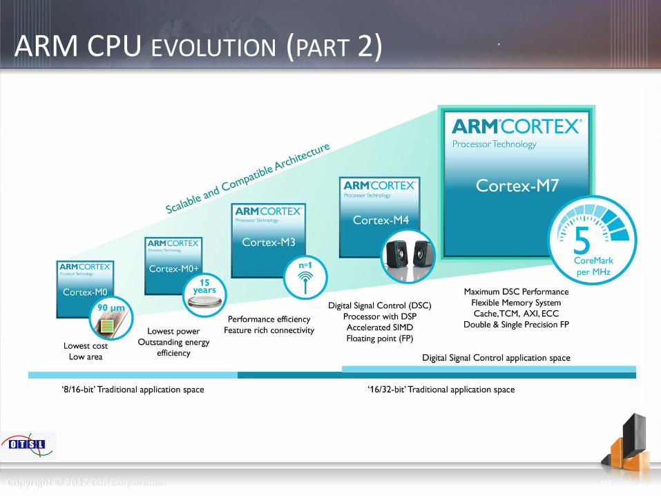
ARM CPU EVOLUTION (PART 2)
10Copyright copy 2017 DSR Corporation
2017
STM32F4 DISCOVERY KIT
STM32F4DISCOVERY
12Copyright copy 2017 DSR Corporation
ST-LINKV2Programming
tool
Reset button
User button
USBOTG
Audio Jack
STM32F407VGT6
STM32F4DISCOVERY
13Copyright copy 2017 DSR Corporation
Hardware block diagram Top layout
STM32F4DISCOVERY FEATURES STM32F407VGT6 MCU featuring 1 MB of Flash memory 192 KB of RAM
On-board ST-LINKV2 with selection mode switch
Board power supply through USB bus or from an external 5V
External application power supply 3V and 5V
LIS302DL ST MEMS motion sensor 3-axis digital output accelerometer
MP45DT02 ST MEMS audio sensor omnidirectional digital microphone
CS43L22 audio DAC with integrated class D speaker driver
Eight LEDs
LD1 (redgreen) for USB communication
LD2 (red) for 33V power on
Four user LEDs LD3 (orange) LD4 (green) LD5 (red) and LD6 (blue)
2 USB OTG LEDs LD7 (green) VBus and LD8 (red) over-current
Two pushbuttons (user and reset)
USB OTG with micro-AB connector
14Copyright copy 2017 DSR Corporation
USEFUL LINKS
15Copyright copy 2017 DSR Corporation
STM32F4DISCOVERY Product page
User manual
STM32F4DISCOVERY board firmware package including 22 examples
2017
STM32F407VGT6 MCU
ARM CORTEX M4 CORE
17Copyright copy 2017 DSR Corporation
STM32F407VGT6 BLOCKS
18Copyright copy 2017 DSR Corporation
STM32F407VGT6 CORE MAIN FEATURES
19Copyright copy 2017 DSR Corporation
ARM 32-bit Cortextrade-M4 CPU (168 MHz 1 Mbyte of Flash memory 192+4 Kbytes of SRAM including 64-Kbyte of CCM data RAM)
3times12-bit AD converters 2times12-bit DA converters General-purpose DMA 16-stream DMA controller Twelve 16-bit and two 32-bit timers with PWM or pulse counters Serial wire debug (SWD) amp JTAG interfaces Up to 140 IO ports with interrupt capability Up to 3 times I2C interfaces (SMBusPMBus) Up to 4 USARTs2 UARTs Up to 3 SPIs (42 Mbitss) 2 times CAN interfaces (20B Active) USB 20 full-speed devicehostOTG controller 10100 Ethernet MAC with dedicated DMA 8- to 14-bit parallel camera interface up to 54 Mbytess LCD parallel interface 80806800 modes
USEFUL LINKS
20Copyright copy 2017 DSR Corporation
STM32F407VG product page
Reference manual including functional and register description
Other documentation
SPL Library documentation
2017
STM32F407VGT6 MCU
POPULAR DEVELOPMENT TOOLS FOR CORTEX-M4
22Copyright copy 2017 DSR Corporation
Atmel Studio by Atmel (based on Visual Studio and GNU GCC Toolchain)
Code Composer Studio by Texas Instruments CoIDE by CooCox Eclipse as IDE with GNU Tools as compilerlinker eg aided
with GNU ARM Eclipse Plug-ins GNU Tools (aka GCC) for ARM Embedded Processors by ARM
Ltd - free GCC for bare metal IAR Embedded Workbench for ARM by IAR Keil MDK-ARM by Keil Visual Studio by Microsoft as IDE with GNU Tools as
compilerlinker - eg supported by VisualGDB
STM32F4 LIBRARIES
23Copyright copy 2017 DSR Corporation
CMSIS ndash Cortex Microcontroller Interface Standard vendor-independent hardware abstraction layer for the Cortex-M processor series and specifies debugger interfaces
SPL ndash Standard Peripheral Library for STM32 Microcontrollers Implements Hardware Abstraction Layer for STM32 peripherals Often can be downloaded with CMSIS API reference
STM32Cube - Embedded software for STM32 F4 series (HAL low level drivers USB TCPIP File system RTOS Graphic -coming with examples running on ST boards) Modern version of STM32 library from STMicroelectronics
CMSIS - CORTEX MICROCONTROLLER
SOFTWARE INTERFACE STANDARD
24Copyright copy 2017 DSR Corporation
CMSIS DESCRIPTION
25Copyright copy 2017 DSR Corporation
CMSIS-CORE API for the Cortex-M processor core and peripherals It provides at standardized interface for Cortex-M0 Cortex-M3 Cortex-M4 SC000 and SC300
CMSIS-DSP DSP Library Collection CMSIS-RTOS API Common API for Real-Time operating systems CMSIS-SVD System View Description for Peripherals Describes the
peripherals of a device in an XML file and can be used to create peripheral awareness in debuggers or header files with peripheral register and interrupt definitions
CMSIS-DAP Debug Access Port Standardized firmware for a Debug Unit that connects to the CoreSight Debug Access Port CMSIS-DAP is distributed as separate package and well suited for integration on evaluation boards This component is provided as separate download
2017
Programming STM32F407
MEMORY ORGANIZATION
27Copyright copy 2017 DSR Corporation
At startup boot pins are used to select one out of three boot options Boot from user Flash Boot from system
memory Boot from embedded
SRAM
Memory access overview 32-bit data bus 4 Gb common memory
space for flash internal ram peripherals external ram debug blocks etc
Unaligned data access Bit-band method
THE CORTEX-M3M4 REGISTERS
28Copyright copy 2017 DSR Corporation
CHIPSET FREQUENCY CONFIGURATION
29Copyright copy 2017 DSR Corporation
Three different clock sources can be used to drive the system clock (SYSCLK)
HSI oscillator clock signal is generated from an internal 16 MHz RC oscillator and can be used directly as a system clock or used as PLL input
HSE oscillator clock signal can be generated from external crystalceramic resonator or external user clock
Main PLL (PLL) clock featuring high speed system clock (up to 168 MHz) and clock for the USB OTG FS (48 MHz) the random analog generator (le48 MHz) and the SDIO (le 48 MHz)
SYSCLK configuration for STM32F4DISCOVERY board
SYSCLK (system_ stm32f4xxh) = PLL_VCO PLL_PPLL_VCO(system_ stm32f4xxh) = (HSE_VALUE or HSI_VALUE PLL_M) PLL_NHSE_VALUE (stm32f4xxh) = 8 000 000 Hz
GPIO CONFIGURATION
30Copyright copy 2017 DSR Corporation
Configuration registers GPIOx_MODER GPIOx_OTYPER GPIOx_OSPEEDR and GPIOx_PUPDR
Data registers GPIOx_IDR and GPIOx_ODRSetreset register GPIOx_BSRRLocking register GPIOx_LCKR Alternate function selection registers GPIOx_AFRH and GPIOx_AFRL
To configuring GPIO using SPL driver Include stm32f4xx_gpioh in your project Enable the GPIO AHB clock using the following function
RCC_AHB1PeriphClockCmd(RCC_AHB1Periph_GPIOx ENABLE) Configure the GPIO pin(s) using GPIO_Init() To get the level of a pin configured in input mode use
GPIO_ReadInputDataBit() To setreset the level of a pin configured in output mode use
GPIO_SetBits()GPIO_ResetBits()
STM32F407 TIMERS
31Copyright copy 2017 DSR Corporation
General-purpose timers (TIM2 to TIM5) 16-bit (TIM3 and TIM4) 32-bit (TIM2 and TIM5) up down updown auto-reload counters
General-purpose timers (TIM9 to TIM14) 16-bit auto-reload upcounter
Advanced-control timers (TIM1ampTIM8) 16-bit up down updown auto-reload counter Used for 3-phase motor control
Basic timers (TIM6ampTIM7) 16-bit auto-reload upcounter
TIMERS CONFIGURATION
32Copyright copy 2017 DSR Corporation
Timer clock configurationHCLK = SYSCLKPCLK1 = HCLK 4TIM_CLK = 2PCLK1 = SYSCLK 2
To configuring Timers using SPL driverbull Include stm32f4xx_timhbull Enable TIM clock using RCC_APBxPeriphClockCmd(RCC_APBxPeriph_TIMx
ENABLE) functionbull Fill the TIM_TimeBaseInitStruct with the desired parametersbull Call TIM_TimeBaseInit(TIMx ampTIM_TimeBaseInitStruct) to configure the Time
Base unit with the corresponding configurationbull Enable the NVIC if you need to generate the update interruptbull Enable the corresponding interrupt using the function TIM_ITConfig(TIMx
TIM_IT_Update)bull Call the TIM_Cmd(ENABLE) function to enable the TIM counter
INTERRUPTS AND EVENTS
33Copyright copy 2017 DSR Corporation
Nested vectored interrupt controller (NVIC)The nested vector interrupt controller NVIC includes the following features
82 maskable interrupt channels for STM32F407xx 16 programmable priority levels (4 bits of interrupt priority are used) low-latency exception and interrupt handling power management control implementation of system control registers
The NVIC and the processor core interface are closely coupled which enables low latency interrupt processing and efficient processing of late arriving interrupts
External interruptevent controller (EXTI)The external interruptevent controller consists of up to 23 edge detectors for generating eventinterrupt requests Each input line can be independently configured to select the type (interrupt or event) and the corresponding trigger event (rising or falling or both) Each line can also masked independently A pending register maintains the status line of the interrupt requests
CMSIS NVIC DRIVER
34Copyright copy 2017 DSR Corporation
Definitions mischInterrupt table startup_stm32F4xxxs
Define your interrupt handler Configure the NVIC Priority Grouping using NVIC_PriorityGroupConfig() Enable and Configure the priority of the selected IRQ Channels using NVIC_Init()
ExampleNVIC_InitTypeDef nvic_structnvic_structNVIC_IRQChannel = TIM2_IRQnnvic_structNVIC_IRQChannelPreemptionPriority = 0nvic_structNVIC_IRQChannelSubPriority = 1nvic_structNVIC_IRQChannelCmd = ENABLENVIC_Init(ampnvic_struct)
35Copyright copy 2017 DSR Corporation
Is there any questions
2017
Thank You

2017
STM32F4 DISCOVERY KIT
STM32F4DISCOVERY
12Copyright copy 2017 DSR Corporation
ST-LINKV2Programming
tool
Reset button
User button
USBOTG
Audio Jack
STM32F407VGT6
STM32F4DISCOVERY
13Copyright copy 2017 DSR Corporation
Hardware block diagram Top layout
STM32F4DISCOVERY FEATURES STM32F407VGT6 MCU featuring 1 MB of Flash memory 192 KB of RAM
On-board ST-LINKV2 with selection mode switch
Board power supply through USB bus or from an external 5V
External application power supply 3V and 5V
LIS302DL ST MEMS motion sensor 3-axis digital output accelerometer
MP45DT02 ST MEMS audio sensor omnidirectional digital microphone
CS43L22 audio DAC with integrated class D speaker driver
Eight LEDs
LD1 (redgreen) for USB communication
LD2 (red) for 33V power on
Four user LEDs LD3 (orange) LD4 (green) LD5 (red) and LD6 (blue)
2 USB OTG LEDs LD7 (green) VBus and LD8 (red) over-current
Two pushbuttons (user and reset)
USB OTG with micro-AB connector
14Copyright copy 2017 DSR Corporation
USEFUL LINKS
15Copyright copy 2017 DSR Corporation
STM32F4DISCOVERY Product page
User manual
STM32F4DISCOVERY board firmware package including 22 examples
2017
STM32F407VGT6 MCU
ARM CORTEX M4 CORE
17Copyright copy 2017 DSR Corporation
STM32F407VGT6 BLOCKS
18Copyright copy 2017 DSR Corporation
STM32F407VGT6 CORE MAIN FEATURES
19Copyright copy 2017 DSR Corporation
ARM 32-bit Cortextrade-M4 CPU (168 MHz 1 Mbyte of Flash memory 192+4 Kbytes of SRAM including 64-Kbyte of CCM data RAM)
3times12-bit AD converters 2times12-bit DA converters General-purpose DMA 16-stream DMA controller Twelve 16-bit and two 32-bit timers with PWM or pulse counters Serial wire debug (SWD) amp JTAG interfaces Up to 140 IO ports with interrupt capability Up to 3 times I2C interfaces (SMBusPMBus) Up to 4 USARTs2 UARTs Up to 3 SPIs (42 Mbitss) 2 times CAN interfaces (20B Active) USB 20 full-speed devicehostOTG controller 10100 Ethernet MAC with dedicated DMA 8- to 14-bit parallel camera interface up to 54 Mbytess LCD parallel interface 80806800 modes
USEFUL LINKS
20Copyright copy 2017 DSR Corporation
STM32F407VG product page
Reference manual including functional and register description
Other documentation
SPL Library documentation
2017
STM32F407VGT6 MCU
POPULAR DEVELOPMENT TOOLS FOR CORTEX-M4
22Copyright copy 2017 DSR Corporation
Atmel Studio by Atmel (based on Visual Studio and GNU GCC Toolchain)
Code Composer Studio by Texas Instruments CoIDE by CooCox Eclipse as IDE with GNU Tools as compilerlinker eg aided
with GNU ARM Eclipse Plug-ins GNU Tools (aka GCC) for ARM Embedded Processors by ARM
Ltd - free GCC for bare metal IAR Embedded Workbench for ARM by IAR Keil MDK-ARM by Keil Visual Studio by Microsoft as IDE with GNU Tools as
compilerlinker - eg supported by VisualGDB
STM32F4 LIBRARIES
23Copyright copy 2017 DSR Corporation
CMSIS ndash Cortex Microcontroller Interface Standard vendor-independent hardware abstraction layer for the Cortex-M processor series and specifies debugger interfaces
SPL ndash Standard Peripheral Library for STM32 Microcontrollers Implements Hardware Abstraction Layer for STM32 peripherals Often can be downloaded with CMSIS API reference
STM32Cube - Embedded software for STM32 F4 series (HAL low level drivers USB TCPIP File system RTOS Graphic -coming with examples running on ST boards) Modern version of STM32 library from STMicroelectronics
CMSIS - CORTEX MICROCONTROLLER
SOFTWARE INTERFACE STANDARD
24Copyright copy 2017 DSR Corporation
CMSIS DESCRIPTION
25Copyright copy 2017 DSR Corporation
CMSIS-CORE API for the Cortex-M processor core and peripherals It provides at standardized interface for Cortex-M0 Cortex-M3 Cortex-M4 SC000 and SC300
CMSIS-DSP DSP Library Collection CMSIS-RTOS API Common API for Real-Time operating systems CMSIS-SVD System View Description for Peripherals Describes the
peripherals of a device in an XML file and can be used to create peripheral awareness in debuggers or header files with peripheral register and interrupt definitions
CMSIS-DAP Debug Access Port Standardized firmware for a Debug Unit that connects to the CoreSight Debug Access Port CMSIS-DAP is distributed as separate package and well suited for integration on evaluation boards This component is provided as separate download
2017
Programming STM32F407
MEMORY ORGANIZATION
27Copyright copy 2017 DSR Corporation
At startup boot pins are used to select one out of three boot options Boot from user Flash Boot from system
memory Boot from embedded
SRAM
Memory access overview 32-bit data bus 4 Gb common memory
space for flash internal ram peripherals external ram debug blocks etc
Unaligned data access Bit-band method
THE CORTEX-M3M4 REGISTERS
28Copyright copy 2017 DSR Corporation
CHIPSET FREQUENCY CONFIGURATION
29Copyright copy 2017 DSR Corporation
Three different clock sources can be used to drive the system clock (SYSCLK)
HSI oscillator clock signal is generated from an internal 16 MHz RC oscillator and can be used directly as a system clock or used as PLL input
HSE oscillator clock signal can be generated from external crystalceramic resonator or external user clock
Main PLL (PLL) clock featuring high speed system clock (up to 168 MHz) and clock for the USB OTG FS (48 MHz) the random analog generator (le48 MHz) and the SDIO (le 48 MHz)
SYSCLK configuration for STM32F4DISCOVERY board
SYSCLK (system_ stm32f4xxh) = PLL_VCO PLL_PPLL_VCO(system_ stm32f4xxh) = (HSE_VALUE or HSI_VALUE PLL_M) PLL_NHSE_VALUE (stm32f4xxh) = 8 000 000 Hz
GPIO CONFIGURATION
30Copyright copy 2017 DSR Corporation
Configuration registers GPIOx_MODER GPIOx_OTYPER GPIOx_OSPEEDR and GPIOx_PUPDR
Data registers GPIOx_IDR and GPIOx_ODRSetreset register GPIOx_BSRRLocking register GPIOx_LCKR Alternate function selection registers GPIOx_AFRH and GPIOx_AFRL
To configuring GPIO using SPL driver Include stm32f4xx_gpioh in your project Enable the GPIO AHB clock using the following function
RCC_AHB1PeriphClockCmd(RCC_AHB1Periph_GPIOx ENABLE) Configure the GPIO pin(s) using GPIO_Init() To get the level of a pin configured in input mode use
GPIO_ReadInputDataBit() To setreset the level of a pin configured in output mode use
GPIO_SetBits()GPIO_ResetBits()
STM32F407 TIMERS
31Copyright copy 2017 DSR Corporation
General-purpose timers (TIM2 to TIM5) 16-bit (TIM3 and TIM4) 32-bit (TIM2 and TIM5) up down updown auto-reload counters
General-purpose timers (TIM9 to TIM14) 16-bit auto-reload upcounter
Advanced-control timers (TIM1ampTIM8) 16-bit up down updown auto-reload counter Used for 3-phase motor control
Basic timers (TIM6ampTIM7) 16-bit auto-reload upcounter
TIMERS CONFIGURATION
32Copyright copy 2017 DSR Corporation
Timer clock configurationHCLK = SYSCLKPCLK1 = HCLK 4TIM_CLK = 2PCLK1 = SYSCLK 2
To configuring Timers using SPL driverbull Include stm32f4xx_timhbull Enable TIM clock using RCC_APBxPeriphClockCmd(RCC_APBxPeriph_TIMx
ENABLE) functionbull Fill the TIM_TimeBaseInitStruct with the desired parametersbull Call TIM_TimeBaseInit(TIMx ampTIM_TimeBaseInitStruct) to configure the Time
Base unit with the corresponding configurationbull Enable the NVIC if you need to generate the update interruptbull Enable the corresponding interrupt using the function TIM_ITConfig(TIMx
TIM_IT_Update)bull Call the TIM_Cmd(ENABLE) function to enable the TIM counter
INTERRUPTS AND EVENTS
33Copyright copy 2017 DSR Corporation
Nested vectored interrupt controller (NVIC)The nested vector interrupt controller NVIC includes the following features
82 maskable interrupt channels for STM32F407xx 16 programmable priority levels (4 bits of interrupt priority are used) low-latency exception and interrupt handling power management control implementation of system control registers
The NVIC and the processor core interface are closely coupled which enables low latency interrupt processing and efficient processing of late arriving interrupts
External interruptevent controller (EXTI)The external interruptevent controller consists of up to 23 edge detectors for generating eventinterrupt requests Each input line can be independently configured to select the type (interrupt or event) and the corresponding trigger event (rising or falling or both) Each line can also masked independently A pending register maintains the status line of the interrupt requests
CMSIS NVIC DRIVER
34Copyright copy 2017 DSR Corporation
Definitions mischInterrupt table startup_stm32F4xxxs
Define your interrupt handler Configure the NVIC Priority Grouping using NVIC_PriorityGroupConfig() Enable and Configure the priority of the selected IRQ Channels using NVIC_Init()
ExampleNVIC_InitTypeDef nvic_structnvic_structNVIC_IRQChannel = TIM2_IRQnnvic_structNVIC_IRQChannelPreemptionPriority = 0nvic_structNVIC_IRQChannelSubPriority = 1nvic_structNVIC_IRQChannelCmd = ENABLENVIC_Init(ampnvic_struct)
35Copyright copy 2017 DSR Corporation
Is there any questions
2017
Thank You
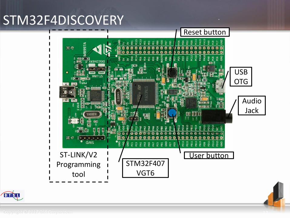
STM32F4DISCOVERY
12Copyright copy 2017 DSR Corporation
ST-LINKV2Programming
tool
Reset button
User button
USBOTG
Audio Jack
STM32F407VGT6
STM32F4DISCOVERY
13Copyright copy 2017 DSR Corporation
Hardware block diagram Top layout
STM32F4DISCOVERY FEATURES STM32F407VGT6 MCU featuring 1 MB of Flash memory 192 KB of RAM
On-board ST-LINKV2 with selection mode switch
Board power supply through USB bus or from an external 5V
External application power supply 3V and 5V
LIS302DL ST MEMS motion sensor 3-axis digital output accelerometer
MP45DT02 ST MEMS audio sensor omnidirectional digital microphone
CS43L22 audio DAC with integrated class D speaker driver
Eight LEDs
LD1 (redgreen) for USB communication
LD2 (red) for 33V power on
Four user LEDs LD3 (orange) LD4 (green) LD5 (red) and LD6 (blue)
2 USB OTG LEDs LD7 (green) VBus and LD8 (red) over-current
Two pushbuttons (user and reset)
USB OTG with micro-AB connector
14Copyright copy 2017 DSR Corporation
USEFUL LINKS
15Copyright copy 2017 DSR Corporation
STM32F4DISCOVERY Product page
User manual
STM32F4DISCOVERY board firmware package including 22 examples
2017
STM32F407VGT6 MCU
ARM CORTEX M4 CORE
17Copyright copy 2017 DSR Corporation
STM32F407VGT6 BLOCKS
18Copyright copy 2017 DSR Corporation
STM32F407VGT6 CORE MAIN FEATURES
19Copyright copy 2017 DSR Corporation
ARM 32-bit Cortextrade-M4 CPU (168 MHz 1 Mbyte of Flash memory 192+4 Kbytes of SRAM including 64-Kbyte of CCM data RAM)
3times12-bit AD converters 2times12-bit DA converters General-purpose DMA 16-stream DMA controller Twelve 16-bit and two 32-bit timers with PWM or pulse counters Serial wire debug (SWD) amp JTAG interfaces Up to 140 IO ports with interrupt capability Up to 3 times I2C interfaces (SMBusPMBus) Up to 4 USARTs2 UARTs Up to 3 SPIs (42 Mbitss) 2 times CAN interfaces (20B Active) USB 20 full-speed devicehostOTG controller 10100 Ethernet MAC with dedicated DMA 8- to 14-bit parallel camera interface up to 54 Mbytess LCD parallel interface 80806800 modes
USEFUL LINKS
20Copyright copy 2017 DSR Corporation
STM32F407VG product page
Reference manual including functional and register description
Other documentation
SPL Library documentation
2017
STM32F407VGT6 MCU
POPULAR DEVELOPMENT TOOLS FOR CORTEX-M4
22Copyright copy 2017 DSR Corporation
Atmel Studio by Atmel (based on Visual Studio and GNU GCC Toolchain)
Code Composer Studio by Texas Instruments CoIDE by CooCox Eclipse as IDE with GNU Tools as compilerlinker eg aided
with GNU ARM Eclipse Plug-ins GNU Tools (aka GCC) for ARM Embedded Processors by ARM
Ltd - free GCC for bare metal IAR Embedded Workbench for ARM by IAR Keil MDK-ARM by Keil Visual Studio by Microsoft as IDE with GNU Tools as
compilerlinker - eg supported by VisualGDB
STM32F4 LIBRARIES
23Copyright copy 2017 DSR Corporation
CMSIS ndash Cortex Microcontroller Interface Standard vendor-independent hardware abstraction layer for the Cortex-M processor series and specifies debugger interfaces
SPL ndash Standard Peripheral Library for STM32 Microcontrollers Implements Hardware Abstraction Layer for STM32 peripherals Often can be downloaded with CMSIS API reference
STM32Cube - Embedded software for STM32 F4 series (HAL low level drivers USB TCPIP File system RTOS Graphic -coming with examples running on ST boards) Modern version of STM32 library from STMicroelectronics
CMSIS - CORTEX MICROCONTROLLER
SOFTWARE INTERFACE STANDARD
24Copyright copy 2017 DSR Corporation
CMSIS DESCRIPTION
25Copyright copy 2017 DSR Corporation
CMSIS-CORE API for the Cortex-M processor core and peripherals It provides at standardized interface for Cortex-M0 Cortex-M3 Cortex-M4 SC000 and SC300
CMSIS-DSP DSP Library Collection CMSIS-RTOS API Common API for Real-Time operating systems CMSIS-SVD System View Description for Peripherals Describes the
peripherals of a device in an XML file and can be used to create peripheral awareness in debuggers or header files with peripheral register and interrupt definitions
CMSIS-DAP Debug Access Port Standardized firmware for a Debug Unit that connects to the CoreSight Debug Access Port CMSIS-DAP is distributed as separate package and well suited for integration on evaluation boards This component is provided as separate download
2017
Programming STM32F407
MEMORY ORGANIZATION
27Copyright copy 2017 DSR Corporation
At startup boot pins are used to select one out of three boot options Boot from user Flash Boot from system
memory Boot from embedded
SRAM
Memory access overview 32-bit data bus 4 Gb common memory
space for flash internal ram peripherals external ram debug blocks etc
Unaligned data access Bit-band method
THE CORTEX-M3M4 REGISTERS
28Copyright copy 2017 DSR Corporation
CHIPSET FREQUENCY CONFIGURATION
29Copyright copy 2017 DSR Corporation
Three different clock sources can be used to drive the system clock (SYSCLK)
HSI oscillator clock signal is generated from an internal 16 MHz RC oscillator and can be used directly as a system clock or used as PLL input
HSE oscillator clock signal can be generated from external crystalceramic resonator or external user clock
Main PLL (PLL) clock featuring high speed system clock (up to 168 MHz) and clock for the USB OTG FS (48 MHz) the random analog generator (le48 MHz) and the SDIO (le 48 MHz)
SYSCLK configuration for STM32F4DISCOVERY board
SYSCLK (system_ stm32f4xxh) = PLL_VCO PLL_PPLL_VCO(system_ stm32f4xxh) = (HSE_VALUE or HSI_VALUE PLL_M) PLL_NHSE_VALUE (stm32f4xxh) = 8 000 000 Hz
GPIO CONFIGURATION
30Copyright copy 2017 DSR Corporation
Configuration registers GPIOx_MODER GPIOx_OTYPER GPIOx_OSPEEDR and GPIOx_PUPDR
Data registers GPIOx_IDR and GPIOx_ODRSetreset register GPIOx_BSRRLocking register GPIOx_LCKR Alternate function selection registers GPIOx_AFRH and GPIOx_AFRL
To configuring GPIO using SPL driver Include stm32f4xx_gpioh in your project Enable the GPIO AHB clock using the following function
RCC_AHB1PeriphClockCmd(RCC_AHB1Periph_GPIOx ENABLE) Configure the GPIO pin(s) using GPIO_Init() To get the level of a pin configured in input mode use
GPIO_ReadInputDataBit() To setreset the level of a pin configured in output mode use
GPIO_SetBits()GPIO_ResetBits()
STM32F407 TIMERS
31Copyright copy 2017 DSR Corporation
General-purpose timers (TIM2 to TIM5) 16-bit (TIM3 and TIM4) 32-bit (TIM2 and TIM5) up down updown auto-reload counters
General-purpose timers (TIM9 to TIM14) 16-bit auto-reload upcounter
Advanced-control timers (TIM1ampTIM8) 16-bit up down updown auto-reload counter Used for 3-phase motor control
Basic timers (TIM6ampTIM7) 16-bit auto-reload upcounter
TIMERS CONFIGURATION
32Copyright copy 2017 DSR Corporation
Timer clock configurationHCLK = SYSCLKPCLK1 = HCLK 4TIM_CLK = 2PCLK1 = SYSCLK 2
To configuring Timers using SPL driverbull Include stm32f4xx_timhbull Enable TIM clock using RCC_APBxPeriphClockCmd(RCC_APBxPeriph_TIMx
ENABLE) functionbull Fill the TIM_TimeBaseInitStruct with the desired parametersbull Call TIM_TimeBaseInit(TIMx ampTIM_TimeBaseInitStruct) to configure the Time
Base unit with the corresponding configurationbull Enable the NVIC if you need to generate the update interruptbull Enable the corresponding interrupt using the function TIM_ITConfig(TIMx
TIM_IT_Update)bull Call the TIM_Cmd(ENABLE) function to enable the TIM counter
INTERRUPTS AND EVENTS
33Copyright copy 2017 DSR Corporation
Nested vectored interrupt controller (NVIC)The nested vector interrupt controller NVIC includes the following features
82 maskable interrupt channels for STM32F407xx 16 programmable priority levels (4 bits of interrupt priority are used) low-latency exception and interrupt handling power management control implementation of system control registers
The NVIC and the processor core interface are closely coupled which enables low latency interrupt processing and efficient processing of late arriving interrupts
External interruptevent controller (EXTI)The external interruptevent controller consists of up to 23 edge detectors for generating eventinterrupt requests Each input line can be independently configured to select the type (interrupt or event) and the corresponding trigger event (rising or falling or both) Each line can also masked independently A pending register maintains the status line of the interrupt requests
CMSIS NVIC DRIVER
34Copyright copy 2017 DSR Corporation
Definitions mischInterrupt table startup_stm32F4xxxs
Define your interrupt handler Configure the NVIC Priority Grouping using NVIC_PriorityGroupConfig() Enable and Configure the priority of the selected IRQ Channels using NVIC_Init()
ExampleNVIC_InitTypeDef nvic_structnvic_structNVIC_IRQChannel = TIM2_IRQnnvic_structNVIC_IRQChannelPreemptionPriority = 0nvic_structNVIC_IRQChannelSubPriority = 1nvic_structNVIC_IRQChannelCmd = ENABLENVIC_Init(ampnvic_struct)
35Copyright copy 2017 DSR Corporation
Is there any questions
2017
Thank You
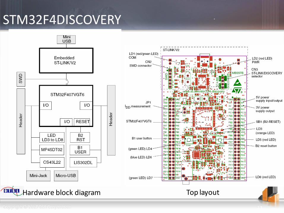
STM32F4DISCOVERY
13Copyright copy 2017 DSR Corporation
Hardware block diagram Top layout
STM32F4DISCOVERY FEATURES STM32F407VGT6 MCU featuring 1 MB of Flash memory 192 KB of RAM
On-board ST-LINKV2 with selection mode switch
Board power supply through USB bus or from an external 5V
External application power supply 3V and 5V
LIS302DL ST MEMS motion sensor 3-axis digital output accelerometer
MP45DT02 ST MEMS audio sensor omnidirectional digital microphone
CS43L22 audio DAC with integrated class D speaker driver
Eight LEDs
LD1 (redgreen) for USB communication
LD2 (red) for 33V power on
Four user LEDs LD3 (orange) LD4 (green) LD5 (red) and LD6 (blue)
2 USB OTG LEDs LD7 (green) VBus and LD8 (red) over-current
Two pushbuttons (user and reset)
USB OTG with micro-AB connector
14Copyright copy 2017 DSR Corporation
USEFUL LINKS
15Copyright copy 2017 DSR Corporation
STM32F4DISCOVERY Product page
User manual
STM32F4DISCOVERY board firmware package including 22 examples
2017
STM32F407VGT6 MCU
ARM CORTEX M4 CORE
17Copyright copy 2017 DSR Corporation
STM32F407VGT6 BLOCKS
18Copyright copy 2017 DSR Corporation
STM32F407VGT6 CORE MAIN FEATURES
19Copyright copy 2017 DSR Corporation
ARM 32-bit Cortextrade-M4 CPU (168 MHz 1 Mbyte of Flash memory 192+4 Kbytes of SRAM including 64-Kbyte of CCM data RAM)
3times12-bit AD converters 2times12-bit DA converters General-purpose DMA 16-stream DMA controller Twelve 16-bit and two 32-bit timers with PWM or pulse counters Serial wire debug (SWD) amp JTAG interfaces Up to 140 IO ports with interrupt capability Up to 3 times I2C interfaces (SMBusPMBus) Up to 4 USARTs2 UARTs Up to 3 SPIs (42 Mbitss) 2 times CAN interfaces (20B Active) USB 20 full-speed devicehostOTG controller 10100 Ethernet MAC with dedicated DMA 8- to 14-bit parallel camera interface up to 54 Mbytess LCD parallel interface 80806800 modes
USEFUL LINKS
20Copyright copy 2017 DSR Corporation
STM32F407VG product page
Reference manual including functional and register description
Other documentation
SPL Library documentation
2017
STM32F407VGT6 MCU
POPULAR DEVELOPMENT TOOLS FOR CORTEX-M4
22Copyright copy 2017 DSR Corporation
Atmel Studio by Atmel (based on Visual Studio and GNU GCC Toolchain)
Code Composer Studio by Texas Instruments CoIDE by CooCox Eclipse as IDE with GNU Tools as compilerlinker eg aided
with GNU ARM Eclipse Plug-ins GNU Tools (aka GCC) for ARM Embedded Processors by ARM
Ltd - free GCC for bare metal IAR Embedded Workbench for ARM by IAR Keil MDK-ARM by Keil Visual Studio by Microsoft as IDE with GNU Tools as
compilerlinker - eg supported by VisualGDB
STM32F4 LIBRARIES
23Copyright copy 2017 DSR Corporation
CMSIS ndash Cortex Microcontroller Interface Standard vendor-independent hardware abstraction layer for the Cortex-M processor series and specifies debugger interfaces
SPL ndash Standard Peripheral Library for STM32 Microcontrollers Implements Hardware Abstraction Layer for STM32 peripherals Often can be downloaded with CMSIS API reference
STM32Cube - Embedded software for STM32 F4 series (HAL low level drivers USB TCPIP File system RTOS Graphic -coming with examples running on ST boards) Modern version of STM32 library from STMicroelectronics
CMSIS - CORTEX MICROCONTROLLER
SOFTWARE INTERFACE STANDARD
24Copyright copy 2017 DSR Corporation
CMSIS DESCRIPTION
25Copyright copy 2017 DSR Corporation
CMSIS-CORE API for the Cortex-M processor core and peripherals It provides at standardized interface for Cortex-M0 Cortex-M3 Cortex-M4 SC000 and SC300
CMSIS-DSP DSP Library Collection CMSIS-RTOS API Common API for Real-Time operating systems CMSIS-SVD System View Description for Peripherals Describes the
peripherals of a device in an XML file and can be used to create peripheral awareness in debuggers or header files with peripheral register and interrupt definitions
CMSIS-DAP Debug Access Port Standardized firmware for a Debug Unit that connects to the CoreSight Debug Access Port CMSIS-DAP is distributed as separate package and well suited for integration on evaluation boards This component is provided as separate download
2017
Programming STM32F407
MEMORY ORGANIZATION
27Copyright copy 2017 DSR Corporation
At startup boot pins are used to select one out of three boot options Boot from user Flash Boot from system
memory Boot from embedded
SRAM
Memory access overview 32-bit data bus 4 Gb common memory
space for flash internal ram peripherals external ram debug blocks etc
Unaligned data access Bit-band method
THE CORTEX-M3M4 REGISTERS
28Copyright copy 2017 DSR Corporation
CHIPSET FREQUENCY CONFIGURATION
29Copyright copy 2017 DSR Corporation
Three different clock sources can be used to drive the system clock (SYSCLK)
HSI oscillator clock signal is generated from an internal 16 MHz RC oscillator and can be used directly as a system clock or used as PLL input
HSE oscillator clock signal can be generated from external crystalceramic resonator or external user clock
Main PLL (PLL) clock featuring high speed system clock (up to 168 MHz) and clock for the USB OTG FS (48 MHz) the random analog generator (le48 MHz) and the SDIO (le 48 MHz)
SYSCLK configuration for STM32F4DISCOVERY board
SYSCLK (system_ stm32f4xxh) = PLL_VCO PLL_PPLL_VCO(system_ stm32f4xxh) = (HSE_VALUE or HSI_VALUE PLL_M) PLL_NHSE_VALUE (stm32f4xxh) = 8 000 000 Hz
GPIO CONFIGURATION
30Copyright copy 2017 DSR Corporation
Configuration registers GPIOx_MODER GPIOx_OTYPER GPIOx_OSPEEDR and GPIOx_PUPDR
Data registers GPIOx_IDR and GPIOx_ODRSetreset register GPIOx_BSRRLocking register GPIOx_LCKR Alternate function selection registers GPIOx_AFRH and GPIOx_AFRL
To configuring GPIO using SPL driver Include stm32f4xx_gpioh in your project Enable the GPIO AHB clock using the following function
RCC_AHB1PeriphClockCmd(RCC_AHB1Periph_GPIOx ENABLE) Configure the GPIO pin(s) using GPIO_Init() To get the level of a pin configured in input mode use
GPIO_ReadInputDataBit() To setreset the level of a pin configured in output mode use
GPIO_SetBits()GPIO_ResetBits()
STM32F407 TIMERS
31Copyright copy 2017 DSR Corporation
General-purpose timers (TIM2 to TIM5) 16-bit (TIM3 and TIM4) 32-bit (TIM2 and TIM5) up down updown auto-reload counters
General-purpose timers (TIM9 to TIM14) 16-bit auto-reload upcounter
Advanced-control timers (TIM1ampTIM8) 16-bit up down updown auto-reload counter Used for 3-phase motor control
Basic timers (TIM6ampTIM7) 16-bit auto-reload upcounter
TIMERS CONFIGURATION
32Copyright copy 2017 DSR Corporation
Timer clock configurationHCLK = SYSCLKPCLK1 = HCLK 4TIM_CLK = 2PCLK1 = SYSCLK 2
To configuring Timers using SPL driverbull Include stm32f4xx_timhbull Enable TIM clock using RCC_APBxPeriphClockCmd(RCC_APBxPeriph_TIMx
ENABLE) functionbull Fill the TIM_TimeBaseInitStruct with the desired parametersbull Call TIM_TimeBaseInit(TIMx ampTIM_TimeBaseInitStruct) to configure the Time
Base unit with the corresponding configurationbull Enable the NVIC if you need to generate the update interruptbull Enable the corresponding interrupt using the function TIM_ITConfig(TIMx
TIM_IT_Update)bull Call the TIM_Cmd(ENABLE) function to enable the TIM counter
INTERRUPTS AND EVENTS
33Copyright copy 2017 DSR Corporation
Nested vectored interrupt controller (NVIC)The nested vector interrupt controller NVIC includes the following features
82 maskable interrupt channels for STM32F407xx 16 programmable priority levels (4 bits of interrupt priority are used) low-latency exception and interrupt handling power management control implementation of system control registers
The NVIC and the processor core interface are closely coupled which enables low latency interrupt processing and efficient processing of late arriving interrupts
External interruptevent controller (EXTI)The external interruptevent controller consists of up to 23 edge detectors for generating eventinterrupt requests Each input line can be independently configured to select the type (interrupt or event) and the corresponding trigger event (rising or falling or both) Each line can also masked independently A pending register maintains the status line of the interrupt requests
CMSIS NVIC DRIVER
34Copyright copy 2017 DSR Corporation
Definitions mischInterrupt table startup_stm32F4xxxs
Define your interrupt handler Configure the NVIC Priority Grouping using NVIC_PriorityGroupConfig() Enable and Configure the priority of the selected IRQ Channels using NVIC_Init()
ExampleNVIC_InitTypeDef nvic_structnvic_structNVIC_IRQChannel = TIM2_IRQnnvic_structNVIC_IRQChannelPreemptionPriority = 0nvic_structNVIC_IRQChannelSubPriority = 1nvic_structNVIC_IRQChannelCmd = ENABLENVIC_Init(ampnvic_struct)
35Copyright copy 2017 DSR Corporation
Is there any questions
2017
Thank You
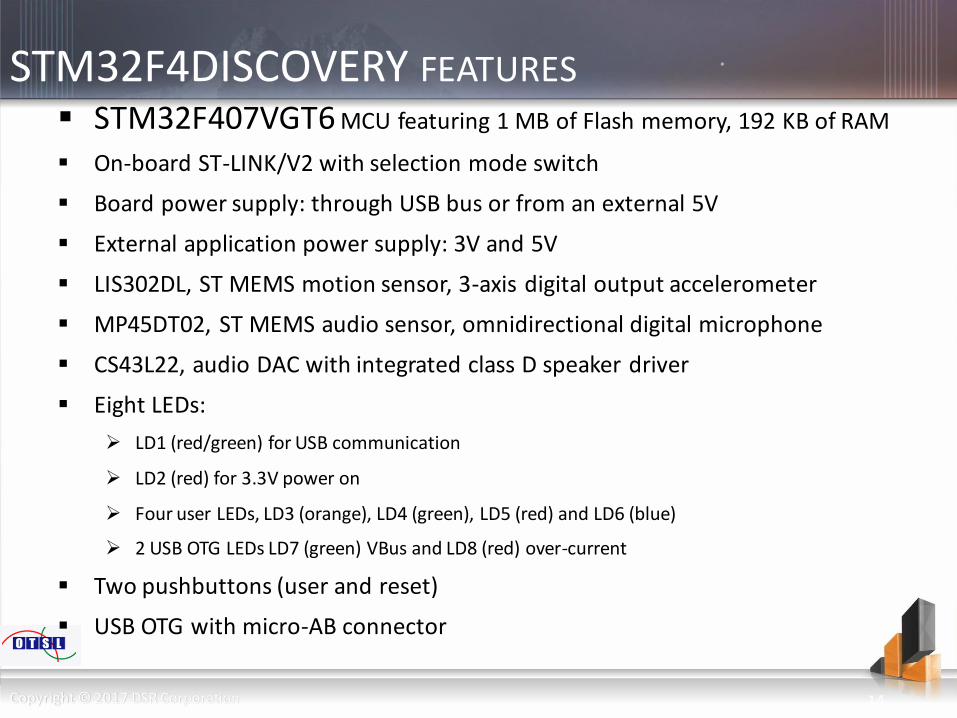
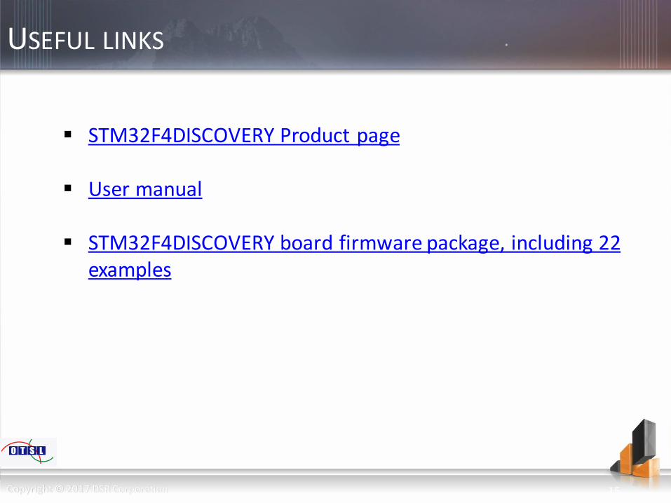
USEFUL LINKS
15Copyright copy 2017 DSR Corporation
STM32F4DISCOVERY Product page
User manual
STM32F4DISCOVERY board firmware package including 22 examples
2017
STM32F407VGT6 MCU
ARM CORTEX M4 CORE
17Copyright copy 2017 DSR Corporation
STM32F407VGT6 BLOCKS
18Copyright copy 2017 DSR Corporation
STM32F407VGT6 CORE MAIN FEATURES
19Copyright copy 2017 DSR Corporation
ARM 32-bit Cortextrade-M4 CPU (168 MHz 1 Mbyte of Flash memory 192+4 Kbytes of SRAM including 64-Kbyte of CCM data RAM)
3times12-bit AD converters 2times12-bit DA converters General-purpose DMA 16-stream DMA controller Twelve 16-bit and two 32-bit timers with PWM or pulse counters Serial wire debug (SWD) amp JTAG interfaces Up to 140 IO ports with interrupt capability Up to 3 times I2C interfaces (SMBusPMBus) Up to 4 USARTs2 UARTs Up to 3 SPIs (42 Mbitss) 2 times CAN interfaces (20B Active) USB 20 full-speed devicehostOTG controller 10100 Ethernet MAC with dedicated DMA 8- to 14-bit parallel camera interface up to 54 Mbytess LCD parallel interface 80806800 modes
USEFUL LINKS
20Copyright copy 2017 DSR Corporation
STM32F407VG product page
Reference manual including functional and register description
Other documentation
SPL Library documentation
2017
STM32F407VGT6 MCU
POPULAR DEVELOPMENT TOOLS FOR CORTEX-M4
22Copyright copy 2017 DSR Corporation
Atmel Studio by Atmel (based on Visual Studio and GNU GCC Toolchain)
Code Composer Studio by Texas Instruments CoIDE by CooCox Eclipse as IDE with GNU Tools as compilerlinker eg aided
with GNU ARM Eclipse Plug-ins GNU Tools (aka GCC) for ARM Embedded Processors by ARM
Ltd - free GCC for bare metal IAR Embedded Workbench for ARM by IAR Keil MDK-ARM by Keil Visual Studio by Microsoft as IDE with GNU Tools as
compilerlinker - eg supported by VisualGDB
STM32F4 LIBRARIES
23Copyright copy 2017 DSR Corporation
CMSIS ndash Cortex Microcontroller Interface Standard vendor-independent hardware abstraction layer for the Cortex-M processor series and specifies debugger interfaces
SPL ndash Standard Peripheral Library for STM32 Microcontrollers Implements Hardware Abstraction Layer for STM32 peripherals Often can be downloaded with CMSIS API reference
STM32Cube - Embedded software for STM32 F4 series (HAL low level drivers USB TCPIP File system RTOS Graphic -coming with examples running on ST boards) Modern version of STM32 library from STMicroelectronics
CMSIS - CORTEX MICROCONTROLLER
SOFTWARE INTERFACE STANDARD
24Copyright copy 2017 DSR Corporation
CMSIS DESCRIPTION
25Copyright copy 2017 DSR Corporation
CMSIS-CORE API for the Cortex-M processor core and peripherals It provides at standardized interface for Cortex-M0 Cortex-M3 Cortex-M4 SC000 and SC300
CMSIS-DSP DSP Library Collection CMSIS-RTOS API Common API for Real-Time operating systems CMSIS-SVD System View Description for Peripherals Describes the
peripherals of a device in an XML file and can be used to create peripheral awareness in debuggers or header files with peripheral register and interrupt definitions
CMSIS-DAP Debug Access Port Standardized firmware for a Debug Unit that connects to the CoreSight Debug Access Port CMSIS-DAP is distributed as separate package and well suited for integration on evaluation boards This component is provided as separate download
2017
Programming STM32F407
MEMORY ORGANIZATION
27Copyright copy 2017 DSR Corporation
At startup boot pins are used to select one out of three boot options Boot from user Flash Boot from system
memory Boot from embedded
SRAM
Memory access overview 32-bit data bus 4 Gb common memory
space for flash internal ram peripherals external ram debug blocks etc
Unaligned data access Bit-band method
THE CORTEX-M3M4 REGISTERS
28Copyright copy 2017 DSR Corporation
CHIPSET FREQUENCY CONFIGURATION
29Copyright copy 2017 DSR Corporation
Three different clock sources can be used to drive the system clock (SYSCLK)
HSI oscillator clock signal is generated from an internal 16 MHz RC oscillator and can be used directly as a system clock or used as PLL input
HSE oscillator clock signal can be generated from external crystalceramic resonator or external user clock
Main PLL (PLL) clock featuring high speed system clock (up to 168 MHz) and clock for the USB OTG FS (48 MHz) the random analog generator (le48 MHz) and the SDIO (le 48 MHz)
SYSCLK configuration for STM32F4DISCOVERY board
SYSCLK (system_ stm32f4xxh) = PLL_VCO PLL_PPLL_VCO(system_ stm32f4xxh) = (HSE_VALUE or HSI_VALUE PLL_M) PLL_NHSE_VALUE (stm32f4xxh) = 8 000 000 Hz
GPIO CONFIGURATION
30Copyright copy 2017 DSR Corporation
Configuration registers GPIOx_MODER GPIOx_OTYPER GPIOx_OSPEEDR and GPIOx_PUPDR
Data registers GPIOx_IDR and GPIOx_ODRSetreset register GPIOx_BSRRLocking register GPIOx_LCKR Alternate function selection registers GPIOx_AFRH and GPIOx_AFRL
To configuring GPIO using SPL driver Include stm32f4xx_gpioh in your project Enable the GPIO AHB clock using the following function
RCC_AHB1PeriphClockCmd(RCC_AHB1Periph_GPIOx ENABLE) Configure the GPIO pin(s) using GPIO_Init() To get the level of a pin configured in input mode use
GPIO_ReadInputDataBit() To setreset the level of a pin configured in output mode use
GPIO_SetBits()GPIO_ResetBits()
STM32F407 TIMERS
31Copyright copy 2017 DSR Corporation
General-purpose timers (TIM2 to TIM5) 16-bit (TIM3 and TIM4) 32-bit (TIM2 and TIM5) up down updown auto-reload counters
General-purpose timers (TIM9 to TIM14) 16-bit auto-reload upcounter
Advanced-control timers (TIM1ampTIM8) 16-bit up down updown auto-reload counter Used for 3-phase motor control
Basic timers (TIM6ampTIM7) 16-bit auto-reload upcounter
TIMERS CONFIGURATION
32Copyright copy 2017 DSR Corporation
Timer clock configurationHCLK = SYSCLKPCLK1 = HCLK 4TIM_CLK = 2PCLK1 = SYSCLK 2
To configuring Timers using SPL driverbull Include stm32f4xx_timhbull Enable TIM clock using RCC_APBxPeriphClockCmd(RCC_APBxPeriph_TIMx
ENABLE) functionbull Fill the TIM_TimeBaseInitStruct with the desired parametersbull Call TIM_TimeBaseInit(TIMx ampTIM_TimeBaseInitStruct) to configure the Time
Base unit with the corresponding configurationbull Enable the NVIC if you need to generate the update interruptbull Enable the corresponding interrupt using the function TIM_ITConfig(TIMx
TIM_IT_Update)bull Call the TIM_Cmd(ENABLE) function to enable the TIM counter
INTERRUPTS AND EVENTS
33Copyright copy 2017 DSR Corporation
Nested vectored interrupt controller (NVIC)The nested vector interrupt controller NVIC includes the following features
82 maskable interrupt channels for STM32F407xx 16 programmable priority levels (4 bits of interrupt priority are used) low-latency exception and interrupt handling power management control implementation of system control registers
The NVIC and the processor core interface are closely coupled which enables low latency interrupt processing and efficient processing of late arriving interrupts
External interruptevent controller (EXTI)The external interruptevent controller consists of up to 23 edge detectors for generating eventinterrupt requests Each input line can be independently configured to select the type (interrupt or event) and the corresponding trigger event (rising or falling or both) Each line can also masked independently A pending register maintains the status line of the interrupt requests
CMSIS NVIC DRIVER
34Copyright copy 2017 DSR Corporation
Definitions mischInterrupt table startup_stm32F4xxxs
Define your interrupt handler Configure the NVIC Priority Grouping using NVIC_PriorityGroupConfig() Enable and Configure the priority of the selected IRQ Channels using NVIC_Init()
ExampleNVIC_InitTypeDef nvic_structnvic_structNVIC_IRQChannel = TIM2_IRQnnvic_structNVIC_IRQChannelPreemptionPriority = 0nvic_structNVIC_IRQChannelSubPriority = 1nvic_structNVIC_IRQChannelCmd = ENABLENVIC_Init(ampnvic_struct)
35Copyright copy 2017 DSR Corporation
Is there any questions
2017
Thank You
2017
STM32F407VGT6 MCU
ARM CORTEX M4 CORE
17Copyright copy 2017 DSR Corporation
STM32F407VGT6 BLOCKS
18Copyright copy 2017 DSR Corporation
STM32F407VGT6 CORE MAIN FEATURES
19Copyright copy 2017 DSR Corporation
ARM 32-bit Cortextrade-M4 CPU (168 MHz 1 Mbyte of Flash memory 192+4 Kbytes of SRAM including 64-Kbyte of CCM data RAM)
3times12-bit AD converters 2times12-bit DA converters General-purpose DMA 16-stream DMA controller Twelve 16-bit and two 32-bit timers with PWM or pulse counters Serial wire debug (SWD) amp JTAG interfaces Up to 140 IO ports with interrupt capability Up to 3 times I2C interfaces (SMBusPMBus) Up to 4 USARTs2 UARTs Up to 3 SPIs (42 Mbitss) 2 times CAN interfaces (20B Active) USB 20 full-speed devicehostOTG controller 10100 Ethernet MAC with dedicated DMA 8- to 14-bit parallel camera interface up to 54 Mbytess LCD parallel interface 80806800 modes
USEFUL LINKS
20Copyright copy 2017 DSR Corporation
STM32F407VG product page
Reference manual including functional and register description
Other documentation
SPL Library documentation
2017
STM32F407VGT6 MCU
POPULAR DEVELOPMENT TOOLS FOR CORTEX-M4
22Copyright copy 2017 DSR Corporation
Atmel Studio by Atmel (based on Visual Studio and GNU GCC Toolchain)
Code Composer Studio by Texas Instruments CoIDE by CooCox Eclipse as IDE with GNU Tools as compilerlinker eg aided
with GNU ARM Eclipse Plug-ins GNU Tools (aka GCC) for ARM Embedded Processors by ARM
Ltd - free GCC for bare metal IAR Embedded Workbench for ARM by IAR Keil MDK-ARM by Keil Visual Studio by Microsoft as IDE with GNU Tools as
compilerlinker - eg supported by VisualGDB
STM32F4 LIBRARIES
23Copyright copy 2017 DSR Corporation
CMSIS ndash Cortex Microcontroller Interface Standard vendor-independent hardware abstraction layer for the Cortex-M processor series and specifies debugger interfaces
SPL ndash Standard Peripheral Library for STM32 Microcontrollers Implements Hardware Abstraction Layer for STM32 peripherals Often can be downloaded with CMSIS API reference
STM32Cube - Embedded software for STM32 F4 series (HAL low level drivers USB TCPIP File system RTOS Graphic -coming with examples running on ST boards) Modern version of STM32 library from STMicroelectronics
CMSIS - CORTEX MICROCONTROLLER
SOFTWARE INTERFACE STANDARD
24Copyright copy 2017 DSR Corporation
CMSIS DESCRIPTION
25Copyright copy 2017 DSR Corporation
CMSIS-CORE API for the Cortex-M processor core and peripherals It provides at standardized interface for Cortex-M0 Cortex-M3 Cortex-M4 SC000 and SC300
CMSIS-DSP DSP Library Collection CMSIS-RTOS API Common API for Real-Time operating systems CMSIS-SVD System View Description for Peripherals Describes the
peripherals of a device in an XML file and can be used to create peripheral awareness in debuggers or header files with peripheral register and interrupt definitions
CMSIS-DAP Debug Access Port Standardized firmware for a Debug Unit that connects to the CoreSight Debug Access Port CMSIS-DAP is distributed as separate package and well suited for integration on evaluation boards This component is provided as separate download
2017
Programming STM32F407
MEMORY ORGANIZATION
27Copyright copy 2017 DSR Corporation
At startup boot pins are used to select one out of three boot options Boot from user Flash Boot from system
memory Boot from embedded
SRAM
Memory access overview 32-bit data bus 4 Gb common memory
space for flash internal ram peripherals external ram debug blocks etc
Unaligned data access Bit-band method
THE CORTEX-M3M4 REGISTERS
28Copyright copy 2017 DSR Corporation
CHIPSET FREQUENCY CONFIGURATION
29Copyright copy 2017 DSR Corporation
Three different clock sources can be used to drive the system clock (SYSCLK)
HSI oscillator clock signal is generated from an internal 16 MHz RC oscillator and can be used directly as a system clock or used as PLL input
HSE oscillator clock signal can be generated from external crystalceramic resonator or external user clock
Main PLL (PLL) clock featuring high speed system clock (up to 168 MHz) and clock for the USB OTG FS (48 MHz) the random analog generator (le48 MHz) and the SDIO (le 48 MHz)
SYSCLK configuration for STM32F4DISCOVERY board
SYSCLK (system_ stm32f4xxh) = PLL_VCO PLL_PPLL_VCO(system_ stm32f4xxh) = (HSE_VALUE or HSI_VALUE PLL_M) PLL_NHSE_VALUE (stm32f4xxh) = 8 000 000 Hz
GPIO CONFIGURATION
30Copyright copy 2017 DSR Corporation
Configuration registers GPIOx_MODER GPIOx_OTYPER GPIOx_OSPEEDR and GPIOx_PUPDR
Data registers GPIOx_IDR and GPIOx_ODRSetreset register GPIOx_BSRRLocking register GPIOx_LCKR Alternate function selection registers GPIOx_AFRH and GPIOx_AFRL
To configuring GPIO using SPL driver Include stm32f4xx_gpioh in your project Enable the GPIO AHB clock using the following function
RCC_AHB1PeriphClockCmd(RCC_AHB1Periph_GPIOx ENABLE) Configure the GPIO pin(s) using GPIO_Init() To get the level of a pin configured in input mode use
GPIO_ReadInputDataBit() To setreset the level of a pin configured in output mode use
GPIO_SetBits()GPIO_ResetBits()
STM32F407 TIMERS
31Copyright copy 2017 DSR Corporation
General-purpose timers (TIM2 to TIM5) 16-bit (TIM3 and TIM4) 32-bit (TIM2 and TIM5) up down updown auto-reload counters
General-purpose timers (TIM9 to TIM14) 16-bit auto-reload upcounter
Advanced-control timers (TIM1ampTIM8) 16-bit up down updown auto-reload counter Used for 3-phase motor control
Basic timers (TIM6ampTIM7) 16-bit auto-reload upcounter
TIMERS CONFIGURATION
32Copyright copy 2017 DSR Corporation
Timer clock configurationHCLK = SYSCLKPCLK1 = HCLK 4TIM_CLK = 2PCLK1 = SYSCLK 2
To configuring Timers using SPL driverbull Include stm32f4xx_timhbull Enable TIM clock using RCC_APBxPeriphClockCmd(RCC_APBxPeriph_TIMx
ENABLE) functionbull Fill the TIM_TimeBaseInitStruct with the desired parametersbull Call TIM_TimeBaseInit(TIMx ampTIM_TimeBaseInitStruct) to configure the Time
Base unit with the corresponding configurationbull Enable the NVIC if you need to generate the update interruptbull Enable the corresponding interrupt using the function TIM_ITConfig(TIMx
TIM_IT_Update)bull Call the TIM_Cmd(ENABLE) function to enable the TIM counter
INTERRUPTS AND EVENTS
33Copyright copy 2017 DSR Corporation
Nested vectored interrupt controller (NVIC)The nested vector interrupt controller NVIC includes the following features
82 maskable interrupt channels for STM32F407xx 16 programmable priority levels (4 bits of interrupt priority are used) low-latency exception and interrupt handling power management control implementation of system control registers
The NVIC and the processor core interface are closely coupled which enables low latency interrupt processing and efficient processing of late arriving interrupts
External interruptevent controller (EXTI)The external interruptevent controller consists of up to 23 edge detectors for generating eventinterrupt requests Each input line can be independently configured to select the type (interrupt or event) and the corresponding trigger event (rising or falling or both) Each line can also masked independently A pending register maintains the status line of the interrupt requests
CMSIS NVIC DRIVER
34Copyright copy 2017 DSR Corporation
Definitions mischInterrupt table startup_stm32F4xxxs
Define your interrupt handler Configure the NVIC Priority Grouping using NVIC_PriorityGroupConfig() Enable and Configure the priority of the selected IRQ Channels using NVIC_Init()
ExampleNVIC_InitTypeDef nvic_structnvic_structNVIC_IRQChannel = TIM2_IRQnnvic_structNVIC_IRQChannelPreemptionPriority = 0nvic_structNVIC_IRQChannelSubPriority = 1nvic_structNVIC_IRQChannelCmd = ENABLENVIC_Init(ampnvic_struct)
35Copyright copy 2017 DSR Corporation
Is there any questions
2017
Thank You
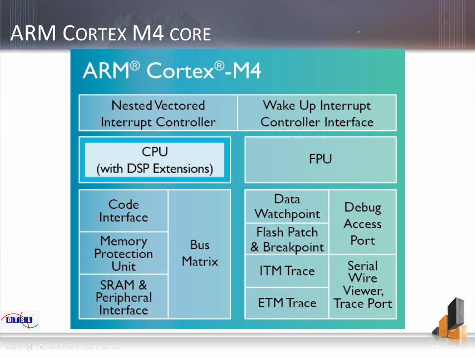
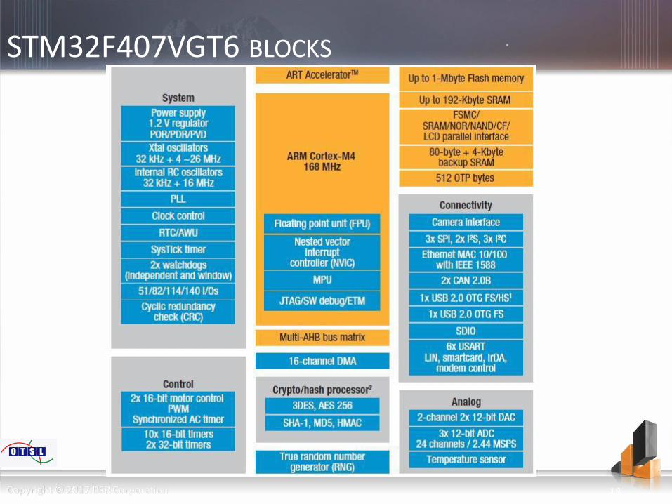
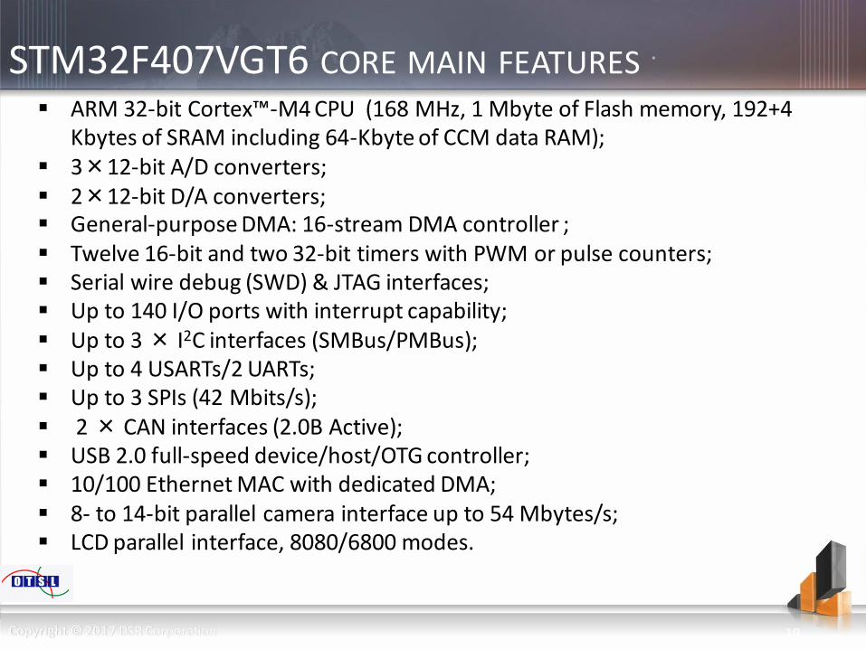
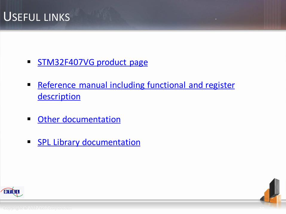

2017
STM32F407VGT6 MCU
POPULAR DEVELOPMENT TOOLS FOR CORTEX-M4
22Copyright copy 2017 DSR Corporation
Atmel Studio by Atmel (based on Visual Studio and GNU GCC Toolchain)
Code Composer Studio by Texas Instruments CoIDE by CooCox Eclipse as IDE with GNU Tools as compilerlinker eg aided
with GNU ARM Eclipse Plug-ins GNU Tools (aka GCC) for ARM Embedded Processors by ARM
Ltd - free GCC for bare metal IAR Embedded Workbench for ARM by IAR Keil MDK-ARM by Keil Visual Studio by Microsoft as IDE with GNU Tools as
compilerlinker - eg supported by VisualGDB
STM32F4 LIBRARIES
23Copyright copy 2017 DSR Corporation
CMSIS ndash Cortex Microcontroller Interface Standard vendor-independent hardware abstraction layer for the Cortex-M processor series and specifies debugger interfaces
SPL ndash Standard Peripheral Library for STM32 Microcontrollers Implements Hardware Abstraction Layer for STM32 peripherals Often can be downloaded with CMSIS API reference
STM32Cube - Embedded software for STM32 F4 series (HAL low level drivers USB TCPIP File system RTOS Graphic -coming with examples running on ST boards) Modern version of STM32 library from STMicroelectronics
CMSIS - CORTEX MICROCONTROLLER
SOFTWARE INTERFACE STANDARD
24Copyright copy 2017 DSR Corporation
CMSIS DESCRIPTION
25Copyright copy 2017 DSR Corporation
CMSIS-CORE API for the Cortex-M processor core and peripherals It provides at standardized interface for Cortex-M0 Cortex-M3 Cortex-M4 SC000 and SC300
CMSIS-DSP DSP Library Collection CMSIS-RTOS API Common API for Real-Time operating systems CMSIS-SVD System View Description for Peripherals Describes the
peripherals of a device in an XML file and can be used to create peripheral awareness in debuggers or header files with peripheral register and interrupt definitions
CMSIS-DAP Debug Access Port Standardized firmware for a Debug Unit that connects to the CoreSight Debug Access Port CMSIS-DAP is distributed as separate package and well suited for integration on evaluation boards This component is provided as separate download
2017
Programming STM32F407
MEMORY ORGANIZATION
27Copyright copy 2017 DSR Corporation
At startup boot pins are used to select one out of three boot options Boot from user Flash Boot from system
memory Boot from embedded
SRAM
Memory access overview 32-bit data bus 4 Gb common memory
space for flash internal ram peripherals external ram debug blocks etc
Unaligned data access Bit-band method
THE CORTEX-M3M4 REGISTERS
28Copyright copy 2017 DSR Corporation
CHIPSET FREQUENCY CONFIGURATION
29Copyright copy 2017 DSR Corporation
Three different clock sources can be used to drive the system clock (SYSCLK)
HSI oscillator clock signal is generated from an internal 16 MHz RC oscillator and can be used directly as a system clock or used as PLL input
HSE oscillator clock signal can be generated from external crystalceramic resonator or external user clock
Main PLL (PLL) clock featuring high speed system clock (up to 168 MHz) and clock for the USB OTG FS (48 MHz) the random analog generator (le48 MHz) and the SDIO (le 48 MHz)
SYSCLK configuration for STM32F4DISCOVERY board
SYSCLK (system_ stm32f4xxh) = PLL_VCO PLL_PPLL_VCO(system_ stm32f4xxh) = (HSE_VALUE or HSI_VALUE PLL_M) PLL_NHSE_VALUE (stm32f4xxh) = 8 000 000 Hz
GPIO CONFIGURATION
30Copyright copy 2017 DSR Corporation
Configuration registers GPIOx_MODER GPIOx_OTYPER GPIOx_OSPEEDR and GPIOx_PUPDR
Data registers GPIOx_IDR and GPIOx_ODRSetreset register GPIOx_BSRRLocking register GPIOx_LCKR Alternate function selection registers GPIOx_AFRH and GPIOx_AFRL
To configuring GPIO using SPL driver Include stm32f4xx_gpioh in your project Enable the GPIO AHB clock using the following function
RCC_AHB1PeriphClockCmd(RCC_AHB1Periph_GPIOx ENABLE) Configure the GPIO pin(s) using GPIO_Init() To get the level of a pin configured in input mode use
GPIO_ReadInputDataBit() To setreset the level of a pin configured in output mode use
GPIO_SetBits()GPIO_ResetBits()
STM32F407 TIMERS
31Copyright copy 2017 DSR Corporation
General-purpose timers (TIM2 to TIM5) 16-bit (TIM3 and TIM4) 32-bit (TIM2 and TIM5) up down updown auto-reload counters
General-purpose timers (TIM9 to TIM14) 16-bit auto-reload upcounter
Advanced-control timers (TIM1ampTIM8) 16-bit up down updown auto-reload counter Used for 3-phase motor control
Basic timers (TIM6ampTIM7) 16-bit auto-reload upcounter
TIMERS CONFIGURATION
32Copyright copy 2017 DSR Corporation
Timer clock configurationHCLK = SYSCLKPCLK1 = HCLK 4TIM_CLK = 2PCLK1 = SYSCLK 2
To configuring Timers using SPL driverbull Include stm32f4xx_timhbull Enable TIM clock using RCC_APBxPeriphClockCmd(RCC_APBxPeriph_TIMx
ENABLE) functionbull Fill the TIM_TimeBaseInitStruct with the desired parametersbull Call TIM_TimeBaseInit(TIMx ampTIM_TimeBaseInitStruct) to configure the Time
Base unit with the corresponding configurationbull Enable the NVIC if you need to generate the update interruptbull Enable the corresponding interrupt using the function TIM_ITConfig(TIMx
TIM_IT_Update)bull Call the TIM_Cmd(ENABLE) function to enable the TIM counter
INTERRUPTS AND EVENTS
33Copyright copy 2017 DSR Corporation
Nested vectored interrupt controller (NVIC)The nested vector interrupt controller NVIC includes the following features
82 maskable interrupt channels for STM32F407xx 16 programmable priority levels (4 bits of interrupt priority are used) low-latency exception and interrupt handling power management control implementation of system control registers
The NVIC and the processor core interface are closely coupled which enables low latency interrupt processing and efficient processing of late arriving interrupts
External interruptevent controller (EXTI)The external interruptevent controller consists of up to 23 edge detectors for generating eventinterrupt requests Each input line can be independently configured to select the type (interrupt or event) and the corresponding trigger event (rising or falling or both) Each line can also masked independently A pending register maintains the status line of the interrupt requests
CMSIS NVIC DRIVER
34Copyright copy 2017 DSR Corporation
Definitions mischInterrupt table startup_stm32F4xxxs
Define your interrupt handler Configure the NVIC Priority Grouping using NVIC_PriorityGroupConfig() Enable and Configure the priority of the selected IRQ Channels using NVIC_Init()
ExampleNVIC_InitTypeDef nvic_structnvic_structNVIC_IRQChannel = TIM2_IRQnnvic_structNVIC_IRQChannelPreemptionPriority = 0nvic_structNVIC_IRQChannelSubPriority = 1nvic_structNVIC_IRQChannelCmd = ENABLENVIC_Init(ampnvic_struct)
35Copyright copy 2017 DSR Corporation
Is there any questions
2017
Thank You
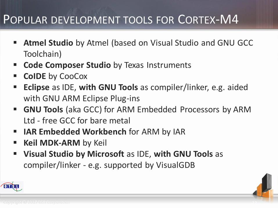
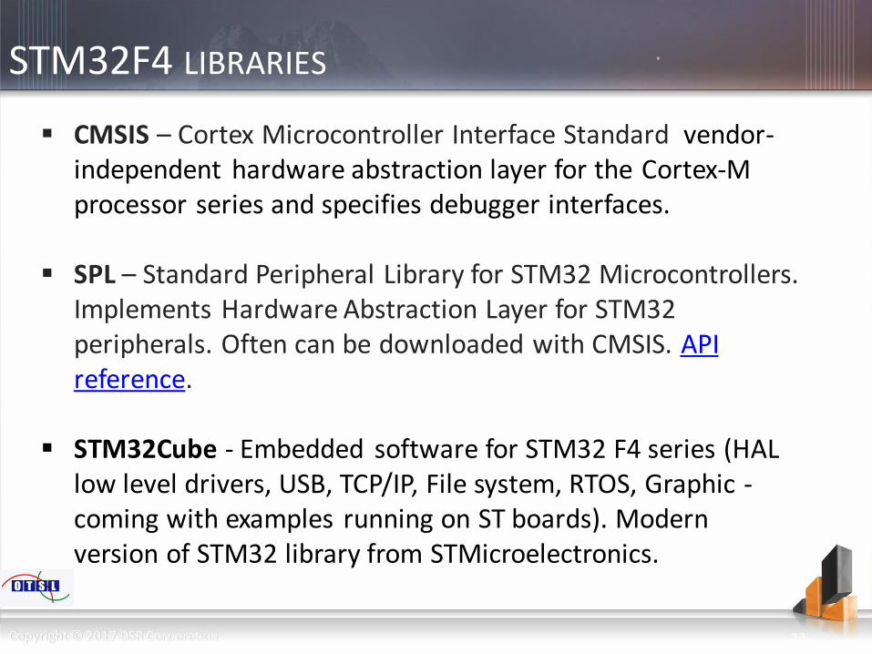
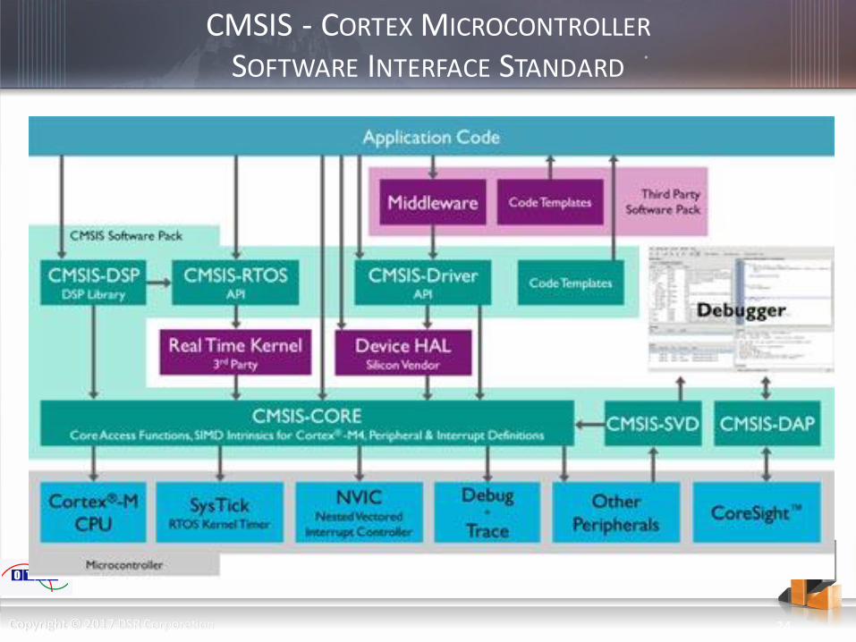
2017
Programming STM32F407
MEMORY ORGANIZATION
27Copyright copy 2017 DSR Corporation
At startup boot pins are used to select one out of three boot options Boot from user Flash Boot from system
memory Boot from embedded
SRAM
Memory access overview 32-bit data bus 4 Gb common memory
space for flash internal ram peripherals external ram debug blocks etc
Unaligned data access Bit-band method
THE CORTEX-M3M4 REGISTERS
28Copyright copy 2017 DSR Corporation
CHIPSET FREQUENCY CONFIGURATION
29Copyright copy 2017 DSR Corporation
Three different clock sources can be used to drive the system clock (SYSCLK)
HSI oscillator clock signal is generated from an internal 16 MHz RC oscillator and can be used directly as a system clock or used as PLL input
HSE oscillator clock signal can be generated from external crystalceramic resonator or external user clock
Main PLL (PLL) clock featuring high speed system clock (up to 168 MHz) and clock for the USB OTG FS (48 MHz) the random analog generator (le48 MHz) and the SDIO (le 48 MHz)
SYSCLK configuration for STM32F4DISCOVERY board
SYSCLK (system_ stm32f4xxh) = PLL_VCO PLL_PPLL_VCO(system_ stm32f4xxh) = (HSE_VALUE or HSI_VALUE PLL_M) PLL_NHSE_VALUE (stm32f4xxh) = 8 000 000 Hz
GPIO CONFIGURATION
30Copyright copy 2017 DSR Corporation
Configuration registers GPIOx_MODER GPIOx_OTYPER GPIOx_OSPEEDR and GPIOx_PUPDR
Data registers GPIOx_IDR and GPIOx_ODRSetreset register GPIOx_BSRRLocking register GPIOx_LCKR Alternate function selection registers GPIOx_AFRH and GPIOx_AFRL
To configuring GPIO using SPL driver Include stm32f4xx_gpioh in your project Enable the GPIO AHB clock using the following function
RCC_AHB1PeriphClockCmd(RCC_AHB1Periph_GPIOx ENABLE) Configure the GPIO pin(s) using GPIO_Init() To get the level of a pin configured in input mode use
GPIO_ReadInputDataBit() To setreset the level of a pin configured in output mode use
GPIO_SetBits()GPIO_ResetBits()
STM32F407 TIMERS
31Copyright copy 2017 DSR Corporation
General-purpose timers (TIM2 to TIM5) 16-bit (TIM3 and TIM4) 32-bit (TIM2 and TIM5) up down updown auto-reload counters
General-purpose timers (TIM9 to TIM14) 16-bit auto-reload upcounter
Advanced-control timers (TIM1ampTIM8) 16-bit up down updown auto-reload counter Used for 3-phase motor control
Basic timers (TIM6ampTIM7) 16-bit auto-reload upcounter
TIMERS CONFIGURATION
32Copyright copy 2017 DSR Corporation
Timer clock configurationHCLK = SYSCLKPCLK1 = HCLK 4TIM_CLK = 2PCLK1 = SYSCLK 2
To configuring Timers using SPL driverbull Include stm32f4xx_timhbull Enable TIM clock using RCC_APBxPeriphClockCmd(RCC_APBxPeriph_TIMx
ENABLE) functionbull Fill the TIM_TimeBaseInitStruct with the desired parametersbull Call TIM_TimeBaseInit(TIMx ampTIM_TimeBaseInitStruct) to configure the Time
Base unit with the corresponding configurationbull Enable the NVIC if you need to generate the update interruptbull Enable the corresponding interrupt using the function TIM_ITConfig(TIMx
TIM_IT_Update)bull Call the TIM_Cmd(ENABLE) function to enable the TIM counter
INTERRUPTS AND EVENTS
33Copyright copy 2017 DSR Corporation
Nested vectored interrupt controller (NVIC)The nested vector interrupt controller NVIC includes the following features
82 maskable interrupt channels for STM32F407xx 16 programmable priority levels (4 bits of interrupt priority are used) low-latency exception and interrupt handling power management control implementation of system control registers
The NVIC and the processor core interface are closely coupled which enables low latency interrupt processing and efficient processing of late arriving interrupts
External interruptevent controller (EXTI)The external interruptevent controller consists of up to 23 edge detectors for generating eventinterrupt requests Each input line can be independently configured to select the type (interrupt or event) and the corresponding trigger event (rising or falling or both) Each line can also masked independently A pending register maintains the status line of the interrupt requests
CMSIS NVIC DRIVER
34Copyright copy 2017 DSR Corporation
Definitions mischInterrupt table startup_stm32F4xxxs
Define your interrupt handler Configure the NVIC Priority Grouping using NVIC_PriorityGroupConfig() Enable and Configure the priority of the selected IRQ Channels using NVIC_Init()
ExampleNVIC_InitTypeDef nvic_structnvic_structNVIC_IRQChannel = TIM2_IRQnnvic_structNVIC_IRQChannelPreemptionPriority = 0nvic_structNVIC_IRQChannelSubPriority = 1nvic_structNVIC_IRQChannelCmd = ENABLENVIC_Init(ampnvic_struct)
35Copyright copy 2017 DSR Corporation
Is there any questions
2017
Thank You
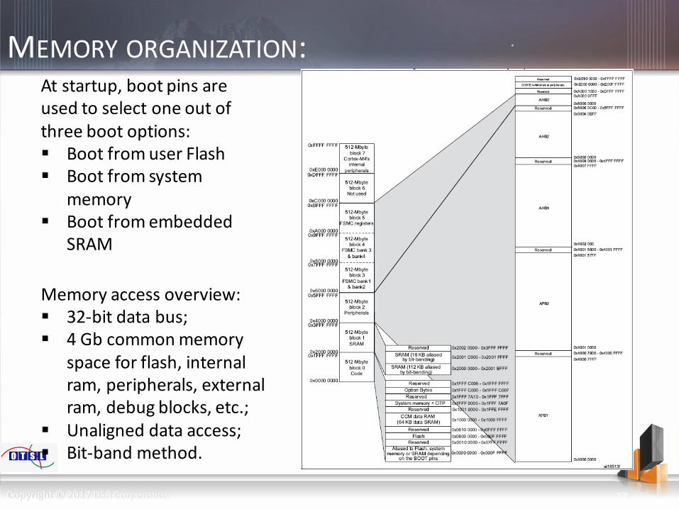
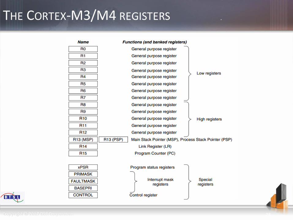
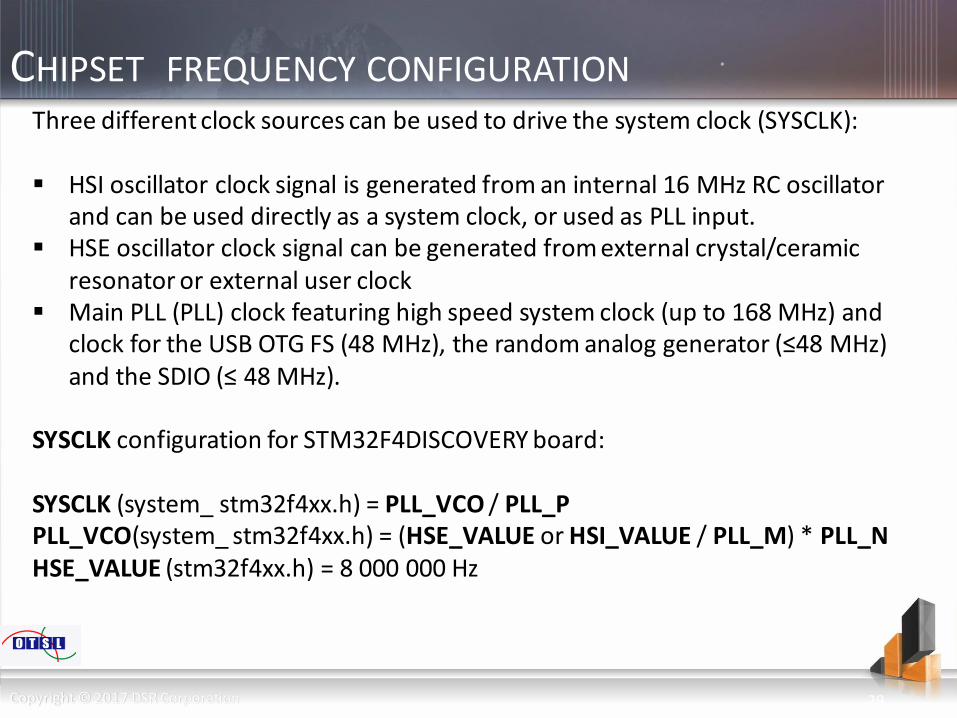
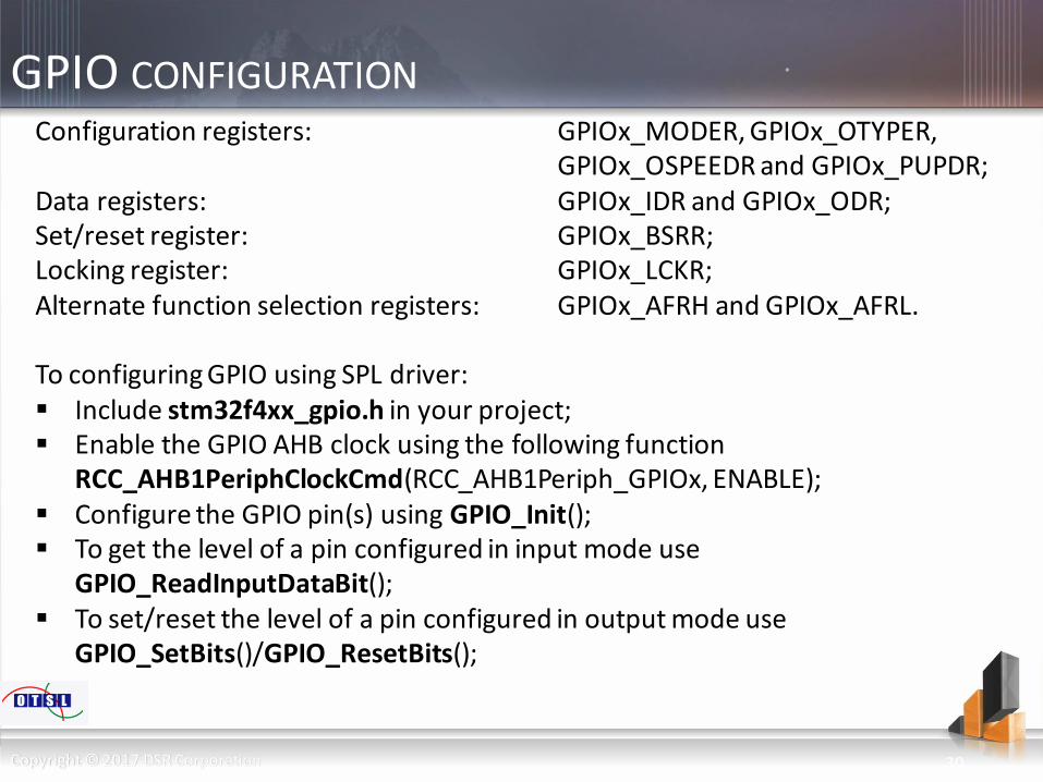
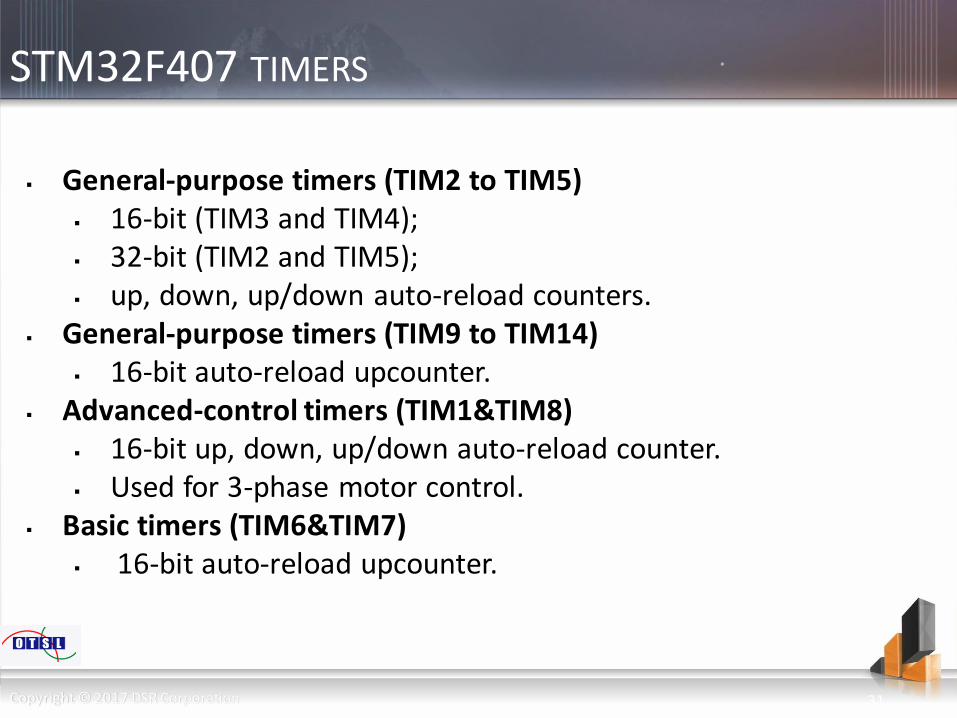
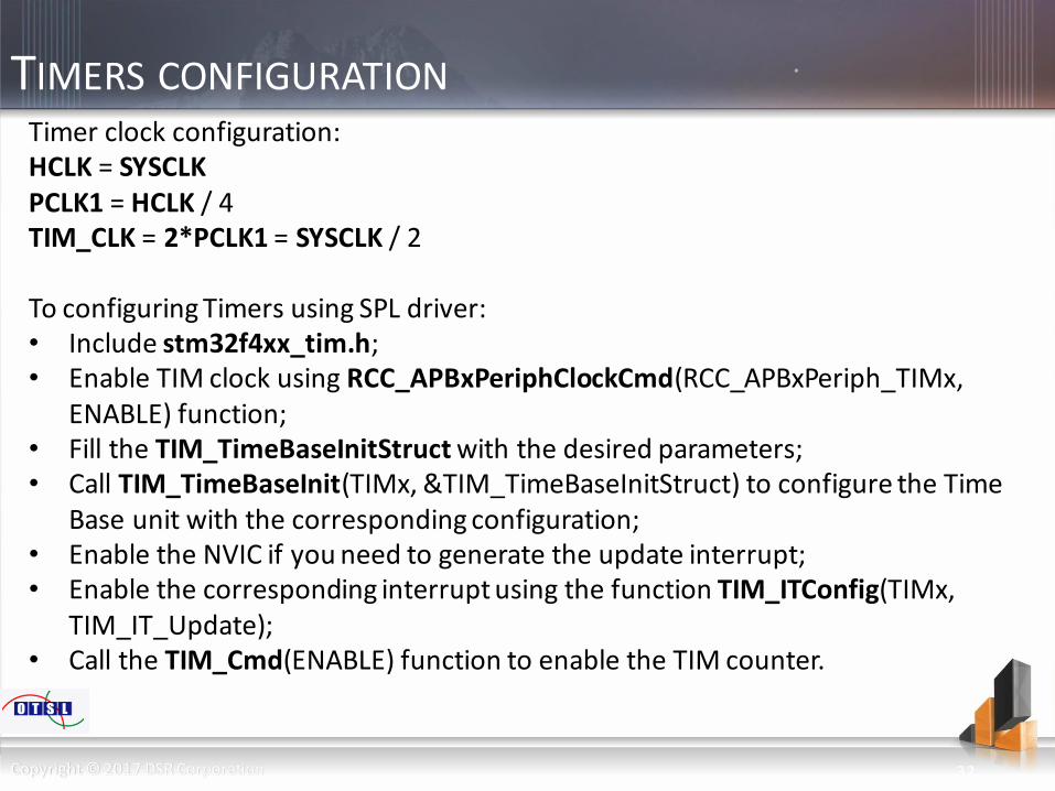
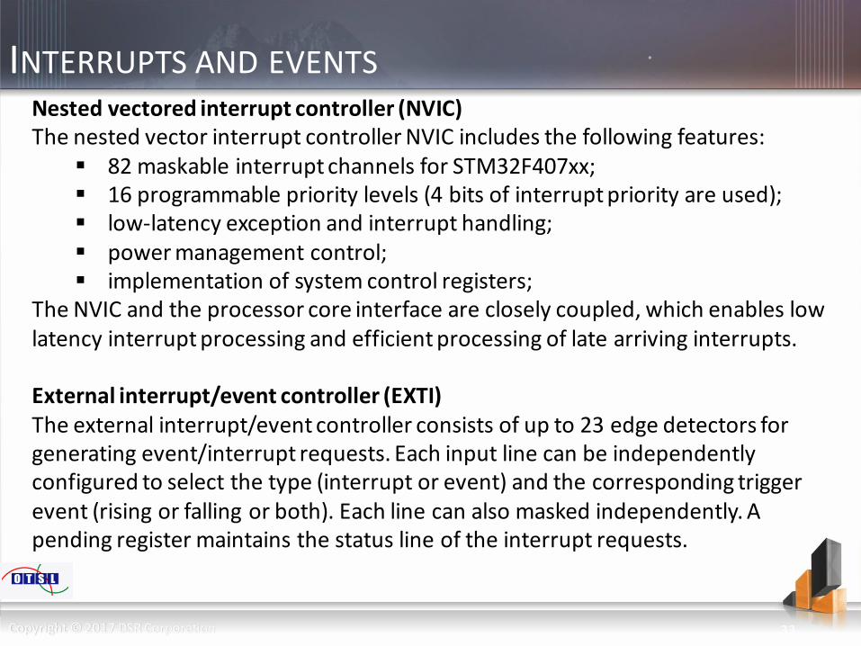
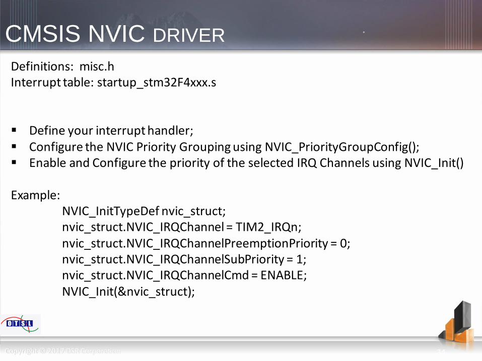

35Copyright copy 2017 DSR Corporation
Is there any questions
2017
Thank You

2017
Thank You