Embed Size (px)
Citation preview

UNCLASSIFIED
AD 2 7 3-8 7 6
ARMED SERVICES TECHNICAL INFORMATION AGENCYARLINGTON HALL STATIONARLINGTON 12, VIRGINIA
w
UNCLASSIFIED
NOTICE: When government or other drawings, speci-fications or other data are used for any purposeother than in connection with a definitely relatedgovernment procurement operation, the U. S.Government thereby incurs no responsibility, nor anyobligation whatsoever; and the fact that the Govern-went may have formulated, furnished, or in any waysupplied the said drawings, specifications, or otherdata is not to be regarded by implication or other-wise as in any manner licensing the holder or anyother person or corporation, or conveying any rightsor permission to manufacture, use or sell anypatented invention that may in any way be relatedthereto.
to 213 876i27 87 Volume I
SSymposium on
PERSONNEL ARMOR
•S. Naval Research LaboratoryOctober 4 - 5,1961
OFFICE OF DIRECTOR OF DEFENSEResearch and Engineering
Washington, D. C.
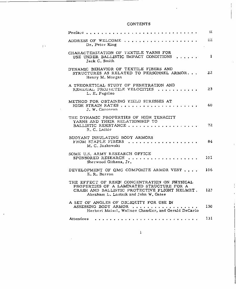
CONTENTS
Preface . . . . . ............ .............................
ADDRESS OF WELCOME . i................... ....Dr. Peter King
CHARACTERIZATION OF TEXTILE YARNS FORUSE UNDER BALLISTIC IMPACT CONDITIONS ......
Jack C. Smith
DYNAMIC BEHAVIOR OF TEXTILE FIBERS ANDSTRUCTURES AS RELATED TO PERSONNEL ARMOR... 22
Henry M. Morgan
A THEORETICAL STUDY OF PENETRATION ANDRESIDUAL PROJEC'FILE VELOCITIES ............ 23
L. E. Fugelso
METHOD FOR OBTAINING YIELD STRESSES ATHIGH STRAIN RATES .......... .............. 60
J. W. Corcoran
THE DYNAMIC PROPERTIES OF HIGH TENACITYYARNS AND THEIR RELATIONSHIP TOBALLISTIC RESISTANCE ........................ 72
R. C. Laible
BUOYANT INSULATING BODY ARMORSFROM STAPLE FIBERS ................... 84
M. C. Jaskowski
SOME U.S. ARMY RESEARCH OFFICESPONSORED RESEARCH ................... 101
Sherwood Githens, Jr.
DEVELOPMENT OF QMC COMPOSITE ARMOR VEST .... 106E. R. Barron
THE EFFECT OF RESIN CONCENTRATION ON PHYSICALPROPERTIES OF A LAMINATED STRUCTURE FOR ACRASH AND BALLISTIC PROTECTIVE FLIGHT HELMET. 123
Abraham L. Lastnik and John W. Gates
A SET OF ANGLES OF OBLIQUITY FOR USE INASSESSING BODY ARMOR .................. 130
Herbert Maisel, Wallace Chandler, and Gerald DeCarlo
Attendees . ............. ............... 131
1
PREFACE
The second Personnel Armor Symposium under auspices of theDepartment of Defense was held at the U. S. Naval Research Laboratoryon 4 and 5 October 1961. The program was arranged so that papers pre-sented on the first day were unclassified. The proceedin;gs have boonreproduced in two volumes, one unclassified and the other classifiedSecret.
Plans for the symposiwrn were made in informal meetings withrepresentatives of the Air Force, Army, Marine Corps and the Navy.Among those individuals contributing to planning] of the program in-cluding subject categories, securing, speakers, etc., were Dr.
George R. Thomas and Mr. M. I. Landsber'g, Quartermaster Research andEngineering Command; Mr. Melvin C. Miller, Office Chief of Ordnance,Dept. of the Army; Mr. Charles N. Gardner, Office of the Ouarter-master General., Dept. of the Army; COL R. J. Oddy, USMC, Office ofNaval Research; LTCOL H. A. Haadd, Hldq. U. S. Marine Corps; Dr.Sanford P. Thompson of NRL; and MAJ T. G. Snipes, USMC LiaisonOfficer at NRL.
Dr. G. R. Irwin, Dr. H. M. Trent, LTCO Robert II. Bennett,and Mr. M. I. Landsberg, Chairmen of the four sessions, each deservescommendation for the outstanding manner in which they stimulated andprovided guidance of discussions following the technical presentations.,En order to provide for uninhibited exchange of information and ideasthe discussions were not recorded.
[ wish to express appreciation to the authors for submittingtheir papers in a form suitable for reproduction and in general forprumptness in supplying the manuscript.
J. FER9CSOGenera.-tairman
ADDRESS OF WELCOME
Dr. Peter KingAssociate Director
U. S. Naval Research LaboratoryWashington 25, D. (.
Good Morning, and Welcome Members of the Symposium -----
First I must bring you the regrets of CAPT Krapf, our Director,who had planned to welcome you this morning. Unfortunately for theSymposium, he was more or less summoned to the Bureau of Budget forone of the reviews which all of us must go through these days. Whenthe Budget Bureau wants to discuss things there seems to be no way ofavoiding the call. I can assure you that he would much rather behere, and I can assure you further that he would be more apt than Iam in giving a welcome to all of you, although it would be no moresincere than mine. Many of you have in the past visited the Labora-tory for other reasons, and we are happy to have you return.
The second annual meeting of the Deoartment of Defense PersonnelArmor Symposium is more than welcome to the Naval Research Laboratory.In reality there have been more than tvo meetings, but not on a formalbasis as they are now organized. It is our good fortune to act ashosts for this second meeting. Not long arwo I looked at the report ofthe First Armor Oymposiu•,u held a bit over a year ago at Natick, andonce again was impressed with the kind of work done, the great effortput into personnel armor, end a bit of its effectiveness. Today, wewill not hear from representatives of DOD, therefore, I hope you won'tmind my taking a few minutes to speak generally about this subject.
My introduction to body or personnel armor came through Dr. irwin,who is Chairman for the first session today. During World War I'[,George had me working with him on Doron. Since that time I havefollowed the field somewhat, but not in great detail. The originaluse of the material seemed to be as flak curtains and other nrmor toprotect flyers. Its use as personnel armor, outside of' helmets,seemed to have reached its climax during the Korean War, where, asstated at your meeting last year, both the Marine Corps and Army feltthat it reduced casualties by 10%. Its use there left no doubt as toits tremendous importance, both physically and mentally to the
iii 1
King
individual fighting man, and thus to the entire Nation as well. Sincethe early days of plastic armor up to the present time, there havebeen no really startling improvements. The gain has been a matter ofa few percent, where an order of magnitude is badly needed. TheAdvisory Group to help guide the development of personnel armor, wiselyrecommended that money should be put into materials) fibers for ex-ample, with strikingly improved strength. Although over the years theArmy has been the major contributor of funds, it was the Marine Corpswho came through with the money to let some contracts for the develop-ment of really high strength material. The fact that the Corps waswilling to invest something of the order of 5% of its total budget inthis field, r think, is the best testimony of the value it places onpersonnel armor. The Marine Corps' objective in employing personnelarmor is to maintain the maximm number of men combat effective on thebattle field. To this end they have maintained continuous, activeinterest in improving body armor. The Army is responsible, too, forretaining the maximum number of men effective on a battle field, and,thus, has an interest in body armor; also, all sorts of protectiveclothing, gas masks, and cold weather gear are part of the over-allpicture, but today the Symposium is concerned with all aspects ofarmor. Any improvement made here will undoubtedly be valuable insome of the other kinds of clothing. There is here a rich field, butunless a really important improvement is made, a great deal of effortwill have been wasted. Funds have been budgeted for fundamental workin materials. When the improved materials become available, thedesigner can reduce the weight necessary for protection and, thus,again increase the effectiveness of the man.
Today, with our increased emphasis on preparation for limitedwar, the subject which you are gathered to explore, seems more impor-tant than it did even a year ago. Anything which will help Army,Navy, Marine Corps, and Air Force to improve its position in limitedwar is certainly of national concern. The fact that you are here in-dicates that you, too, are concerned. Whether we are successful inhaving a really important improvement depends upon you.
AJLtnough recognizable advances have been made during the yearscovered by these sessions, it would be well on occasion to look to thefuture and think about those improvements which would be helpfultoward increasing our military posture. Some of these are: (1) asignificant improvement in the ballistic resistance of armor materials,(2) a more complete understanding of the effects of wounds on theability of a foot soldier to perform defined, and perhaps limited,functions, (3) the establishment of more definitive criteria for theprotection needed under various tactical situations such as brushwarfare, atomic attack, and bacteriological warfare, and (4) thedevelopment of a more definitive policy on how and when personnelarmor is to be employed.
Once again let me repeat, we are happy to be the hosts for theSymposium. We feel the subject matter has increased in importance inthe past few months, and hope that this exchange of information will
iv 2
King
lead to an accelerated program in this field.
INTRODUCTION OF DR. GEORGE IRWIN ------
The Chairman for your first session is Dr. George Irwin of ourLaboratory, Superintendent of the Mechanics Division. Dr. Irwin hasbeen interested in armor for many years. As a matter of fact, duringWorld War II he went to Okinawa before the shooting was over togather some data first hand on the effectiveness, both of our handgrenades and armor. George is a man who had spent a long time inballistics, measuring velocities and small intervals of time. However,on his return from Okinawa I remember speaking with him, and he toldme that he had finally found an interval of time too short to bemeasured. I couldn't imagine what it was, and had to ask him for theexplanation. He said that it was the interval between the cry of'halt' from a Marine and the shot that followed.
V 3
CHARACTERIZATION OF TEXTILE YARNS FOR 1SEUNDER BALLISTIC IMPACT CONDITIONS
Jack C. SmithTextiles Section
National Bureau of StandardsWashinfgton 25, D. C.
Of the various types of flexible personnel armor that havebeen developed, one of the simplest consists of a series of layers ofheavy cloth. This type of armor is surprisingly effective when thecloth is made from a suitable material, such as high-tenacity nylon.In the developmei fl" of this arotrc, many inds of materials, differentkinds of weaves, diffcrent finishing treatments, different types ofconstruction, and othýer variations have been tested. Thus it shouldnow be possible An the design of personnel armor to incorporate im-provements resulting from this vast empirical development program.
From this point of view further improvement depends mostly upon theuse cf materials superior tc those used at present.
However, it is also possible that improvements could resultfrom a better understanding of' the mechanism by which the armor-material is able tr. abscrb th.e energy of a >r•,rpne] fragment travel-Ing at ballistic veloclies. The problem posed here is extremely
complicated, but at least some of its simpler aspects are now under-stood. This paper deals with: one of these aspects; namely, tjebehavior of a long textile yarn struck transversely by a high speedprojectile. Theories required for understanding this behavior havebeen developed by Taylor, von Karman and others, and have been re-viewed and extended in a series of papers by the author [1-4].
Analysis of the transverse impact problem has provided abetter understanding of how strain energy is propagated along afilament, and has introduced the concepts of longitudinal and trans-
verse critical velocities. The ideas discussed have wide applica-bility and can be profitably used to guide further research.
LONGITUDINAL IMPACT THEORY
Before discussing the problem of transverse impact, it willbe necessary to consider the case of a long filament impacted in
I
Smith
tension at one end. Consider, therefore, a semi-infinite filamentlying along the positive X axis with one end at the origin. IR isassumed that the tension-strain curve applicable under the impactoonditions being considered, is known for this filament. In additionit is assumed that this tension-strain curve is always concave down-ward. Let the end of the filament at the origin be impacted withvelocity v in the negative direction. The impact causes a wave ofvariable strain to propagate longitudinally in the positive directionalong the filament. This wave may be visualized as a train of infin-itesimal wavelets, each wavelet traveling at a different velocity andaddLng an increment of strain to the wave. For example, in figure 1the strain wave is represented schematically by a region of varyingfilament diameter.
The initial wavelet, or strain wave front is propagatedwith velocity Co, given by the equation
l T0
where T is the tension or total force sustained by the filament andis given as a function of the strain E by the tension-strain curve.M in the mass per unit length of the unstrained filament. The slopeof the tension-strain curve in this case is evaluated at zero strain
0).
The velocity of each succeeding wavelet is proportional tothe square root of the slope of the tension-strain curve evaluated atthe strain value of the wavelet. In order that the wavelets do notovertake each other, the slope of the tension-strain curve must de-crease as the strain increases. (The curve must be concave downward.)The final .avelet in the train propagates with velocity C1 given by
C 7d T(2)
The velocities at which the wavelets travel are expressedrelative to a Lagrangian system of coordinates; i.e., a system fixedto the filament moving and extending with it. Filament material inthe wake of the final wavelet is under constant strain ti"
In the wake of each wavelet, m-aterial flows backward towardthe point of impact at a velocity that increases as each waveletpasses. The particle velocity W at which filament material in thefinal wavelet flows is given by
ThiLq velocity is the same as the impact velocity if el does notexceed the breakling strain. In fact, the maximum strin in the
S:iith
filament E achieved as a result of longitudinal impact of velocity
Wl is found by solving equation (3).
When the strain aF Is just equal to the breaking strainthe corresponding impact velocity becomes the critical velocity Wc,or lowest velocity at which the F1ilament breaks immediately upon
impact. Thus this longitudinal critical velocity may be defined as
W tdfT dE (4)
From this definition it is possible to calculate the critical velocityif the tension-strain curve ye] id for critical velocity impact isknown, and if this tension--strain curve is always concave downward,or if the carve is linear, if tie tension-strain curve has a concaveupward position, a mnodif.ied Form rof equation (4) must be applied.This modification is discussed in a recent paper by the author [5].
TRIANSV',ýISE IMPACT THEORY
Consider row the problem, of transverse impact. As in thecase of longitudinal inpact, t.ie filament is required to have a con-cave downward tensirI-,I,.3at curve valId under the impact conditionsconsidered. Wh:en Lhe F'!lameent, is struck transversely by a projectile,two longitudinal strain waves are intiated which prr,pagate inopposite directLions away from t.ie pý,lnt of impact. In the regionbetween the two wave .rorits, mater'ial of the filament is set into
motion towards the point ,Tf impact. Th.is inward-flowing materialforms itself into a transverse wave shaped like an inverted "V" withthe impacting proeoti(le at the vertex. The configuration of thefilament at a Lime . afteor impact is shrown in figure 2.
To, iuderst andi what nal8pens in the filament, let us look atthe sequence of events as th.ey woýuld appear to a filament particle ata distance X from the n,jin of impact as measured along the unstrainedfilament. Let the fi-lacent lie horizontanly and be impacted atvelocity V in the vertical direction. After impact, the particledoes not experience any et'f'ects until- the strain wave front reachesit at a time X/C0 later. Al. this time the filament in the reglon ofthe particle becomes strained anud starts to move horizontally towardthe point of impact. As time goes no. the strain at the particle andthe inward flow velocity increase. The wavelet for the maximum strainreaches the particle at time X/C]. At this time the strain has be-come 61 ai.d tho inward flow velocity W. Mathematical expressions forCo, C,, and W1 are given by equations 1), (2), and (3).
After the strait wove has passed, the strain and velocityof horizontal flow of the particle remain constant until time X/U 1 .This is the time of arrival of the transverse wave front; at thisinstant the particle stops moving horizontally and moves abruptly inthe vertical direction at impact velocity V. The strain El at the
3
Smith
particle remains constant. The velocity U1 of the transverse wavefront relative to a Lagrangian coordinate system can be found fromthe formula
U1 M 1
The tension T1 to be used is found from the tension-strain curve.
If the mass per unit length M, and the tension-strain curveare known, the strain wave front velocity C can be found fromequation (1). However, the velocities CI,, and U2 , defined byequations (2), (3), and (4), can be expresseA only an functions ofthe unknown strain E-. Another relationship is needed in order thatthe value of E1 may be found in terms of the known velocity V and theother known quantities. This relationship is [3,4]
V =\(l + F')2 - [(i2 + C.9 U1 - w112 (6)
Equation (6) has several interesting uses. For instance,in one application, a longitudinal impact velocity W can he foundthat will produce a strain distribution along the filament equivalentto that produced by a transverse impact at velocity V. Again, it
should be nouLed Lhat when the strain resulting from an impact is thebreaking strain tb, WI becomes the longitudinal critical velocity Wc,and V becomes Vcthe transverse critical velocity or lowest velocityat which the filament will break immediately upon transverse impact.This velocity is given by
VZ i1+E)2 U2 (l+ b) -wcl2 (7)
where Ub is found by substituting values of the breaking strain Fband breaking tension Tb into equation (5).
POWER ABSORPTIUN IN A FILJUAENT STRUCK TRANSVERSELY
When a filwrment is struck transversely by a flying pro-Jectile, energy of the projectile is converted in the filament tostrain energy, kinetic energy of flow in the direction of the fila-ment, and kinetic energy of transverse motion In the V-shaped wave.To calculate these different eneroy components, consider first thestrain distribution along a semi-infinite filanent t seconds aftertensile impact at one end at velocity Wl. This strain distributionis depicted in figure 3. Here the strain e is plotted for points Xalong the length of the filament. Distances along the filament areexpressed relative to a Lagrangian coordinate system. in this figure
it is seen that a wevelet increasing the strain by an increment dctravels a distance Ct, and causes the filament to increase in lengthby an amount Ctde = tdW, where dW is the increase in particle
velocity. Because of a tensile force T acting along the filament thestrain energy is Increased by an amcunt tTdW. The total strain
A
Smith
energy in the filament is therefore equal to I d
TdWdeto Td& .
By a similar argument it can be shown that the kineticenergy of longitudinal motion given to the filament is
MCWVJW - = t IW dT .
In the case of transversp impact there is no longitudinal flow offilament material in the region taken up by the transverse wave, sothat the above expression must be corrected by subtracting thequantity 1/2 MItW] 2 .
Te kinetic energy f'f transverse motion in one side of theV'-shaped wave is given by 1/2 MU1 tV
2 .
If the above quantities are summed up, taking into accountthe strain and kinetic energies on both sides of the point of impact,and the result divided by t, the following expression is obtained forP, the initial rate at which enprgy is absorbed by the filament:
2,{T wz s 1w
Pq=a2i( T dW dF + 2 Jo dT dc- MU Wd 2 + MIJ V2 (8)
Equation (') can be simplified to the form
P = 2MU (9)
by use of the relation
MIJtV2 = 2t T dE + 2t d-MU tW (0)
/ de (10)Jo
This interesting relation, which states that the sum of the strainenergy and longitudinal kinetic energy in the filament is equal. tothe kinetic energy of transverse motion, is easily proved as follows;From equation (6)it is seen that
MUIV2 MUI [2( + cU I -I W W 2 (I + 1 -)U MUW] I 2 0
Therefore it is only necessary to show that
2J1T lf dh + j 1ai (d rip = eM0t + Ce fr 2W (12)
The left hand side of equation (12) reduces to the form
5
Smith
2 J d(TW) = 2 T3Wl, and the right hand side, upon using equation
T 1(5), becomes 2M(U + •i) i(- -- 67 W, = 2 TWI, so that equation (12)
and therefore equation (10) is proved.
THE SELECTION OF TEXTILE YARNS FOR PERSONNEL ARMOR
The function of personnel armor is to absorb the energyfrom an impinging projectile. The armor should be effective againstprojectiles of very high speed and should utilize the least weight ofarmor material possible. The effectiveness of armor composed ofwoven textile yarns will depend upon the conetruction as well as uponthe yarn material used, but the analysis of construction effects isbeyond thc scope of this paper although its great importance isrecognized. In the following discussion, therefore, the characteris-tics of yarn most suitable for absorbing transverse impact are deter-mined. It is assumed that yarns exhibiting these characteristicswill be most effective for use in personnel armor.
A yarn is most effective in stopping a projectile if itabsorbs energy from transverse impact at a higher rate and at higherimpact velocities than other yarns. The average rate of absorptionis roughly proportional to the initial rate given by equation (9).Upon dividing both sides of this equation by M, it is seen that theinitial rate of energy absorption per unit mass of yarn material isproportional to U1 V2 . Thus it appears that a yarn effective inabsorbing transverse impact must have a high transverse criticalvelocity Vc. The high value of U1 which is also required means thatthe transverse wave front propagates rapidly, and the forward motionof the projectile is rapidly distributed over a long length of yarnon both sides of the point of impact.
If the value of U1 given by equation (5) is substituted intoequation (9), it is seen that the initia] rate of energy absorptionper unit mass is proportional to V2 v/T/1 M(l + el). It should benoted at this point that yarn fineness is customarily expressed interms of linear density. For instance, a yarn or filament of 1 texfineness weighs one gram per 1000 meters of length. Thus a quantityTb/M, where Tb is the yarn tension at break, is proportional to thebreaking tenacity expressed in units such as grams per tex. From theexpression above it is apparent that a yarn effective in absorbingtransverse impact energy must have a high breaking tenacity. Themost effective yarn, then, is the one having the highest transversecritical velocity, and one which at the same time has the highestbreaking tenacity.
An interesting question could be posed at this point. Sup-pose that a variety of yarns is available, each yarn with a different
6
Smith
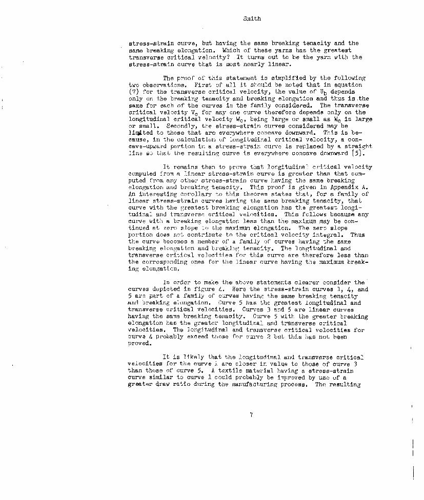
stress-strain curve, but having the same breaking tenacity and thesane breaking elongation. Which of these yarns has the greatesttransverse critical velocity? It turns out to be the yarn with thestress-strain curve that is most nearly linear.
The proof of this statement is simplified by the followingtwo observations. First of all it shculd be noted that in equation(7) for the transverse critical velocity, the value of Ub dependsonly on the breaking tenacity and breaking elongation and thus is thesame for each of the curves in the family considered. The transversecritical velocity V. for any one curve therefore depends only on thelongitudinal critical velocity We, being large or small as We is largeor small. Secondly, the stress-strain curves considered may belinrjted to those that are everywhere concave downward. This is be-cause, in the calculation of longitudinal critical velocity, a con-cave-upward portion in a stress-strain curve is replaced by a straightline so thaL the resulting curve is everywhere concave downward [51.
It remains then to prove that longitudinal critical velocitycomputed from a linear stress-strain curve is greater than that com-puted from any other stress-strain curve having the same breakingelongation and breaking tenacity. This proof is given in Appendix A.An interesting corollary to this theorem states that, for a family oflinear stress-strain curves having the same breaking tenacity, thatcurve with the greatest breaking elongation has the greatest longi-tudinal and transverse critical velocities. This follows because anycurve with a breaking elongation less than the maximum may be con-tinued at zero slope to the maximum elongation. The zero slopeportion does not contribute to the critical velocity integral. Thusthe curve becomes a member of a family of curves having the samebreaking elongation and breakinp,• tenacity. The longitudinal andtransverse critical velocities for this curve are therefore less thanthe corresponding ones for the linear curve having the maximum break-ing elongation.
In order to make the above statements clearer consider thecurves depicted in figure 4. Here 'the stress-strain curves 1, 4, and5 are part of a family of' carves having the same breaking tenacityand breaking elongation. Curve 5 has the greatest longitudinal andtransverse critical velocities. Curves 3 and 5 are linear curveshaving the same breaking tenacity. Curve 5 with the greater breakingelongation has the greater longitudinal and transverse criticalvelocities. The longitudinal and transverse critical velocities forcurve 4 probably exceed those for curve 2 but this has not beenproved.
It is likely that the longitudinal and transverse criticalvelocities for the curve 1 are closer in value to those of curve 3than those of curve 5. A textile material having a stress-straincurve similar to curve I could probably be improved by use of agreater draw ratio during the manufacturing process. The resulting
7
Smith
yarn would have a greater breaking tenacity, a decreased breakingelongation, and Its stress-strain curve would be more linear. In-creased longitudinal and transverse critical velocities should resultif the new drawing conditions are not too extreme.
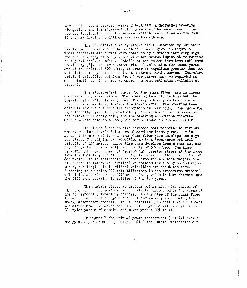
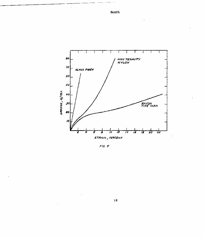
The principles just developed are illustrated by the threetextile yarns having the stress-strain curves given in figure 5.These stress-strain curves were obtained by a method involving high-speed photography of the yarns during transverse impact at velocitiesof apprcximately 40 m/sec. Details of the method have been publishedpreviously [61. The transverse critical velocities for these yarnsare of the order oF 500 m/sec, an order of magnitude greater than thevelocities employed in obtaining the stress-strain curves. Thereforecritical velocities obtained from these curves must be regarded asapproxinations. They are, however, the best estimates available atpresent.
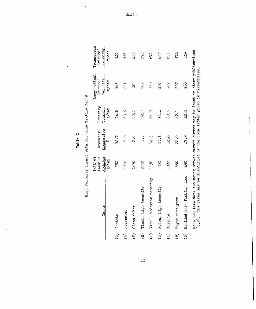
The stress-strain curve for the glass fiber yarn is linearand has a very steep slope. The breaking tenacity is high but thebreaking elongation is very low. The rayon tire yarn has a curvethat bends appreciably towards the strain axis. The breaking ten-acity is low but the breaking elongation is very high. The curve forhigh-tenacity nylon is approximAtely linear, the slope is moderate,the breaking tenacity high, and the breaking elongation moderate.More complete data on these yarns may be found in Tables I and 2.
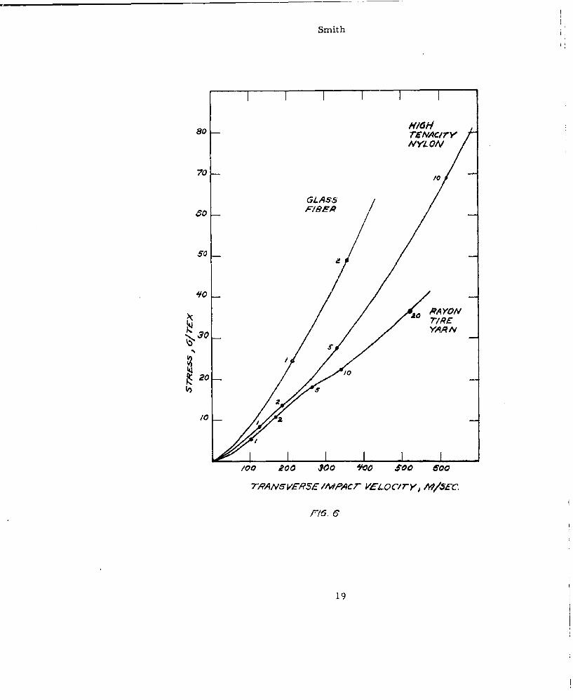
In figure 6 the tensile stresses corresponding to varioustransverse impact velocities are plotted for these yarns. It isapparent from the plots that the glass fiber yarn develops the high-est stress for all impact velocities up to a transverse criticalvelocity of' 433 m/sec. Rayon tire yarn develops less stress but hasthe higher transverse critical velocity of 574 in/sec. The high-tenacity nylon yarn does not develop much greater stress at the lowerimpact velocities, but it has a high transverse critical velocity of685 m/sec. It is interesting to note from Table 2 that despite thedifference in transverse critical velocities for the nylon and rayonyarns, the longitudinal critical velocities are about the same.According to equation (7) this difference in the transverse criticalvelocities depends upon a difference in Ub which in turn depends uponthe different breaking Lenacities of the two yarns.
The numbers placed at various points along the cur-ves offigure 6 denote the maximum percent strains developed in the yarns atthe corresponding impact velocities. In the case of the glass fiberit can be seen that the yarn does not deform very much during theenergy absorption process. It is interesting to note that for impactvelocities near 350 in/sec the glass fiber yarn develops a strain of25I, nylon yarn a 5% strain, and rayon yarn a 10% strain.
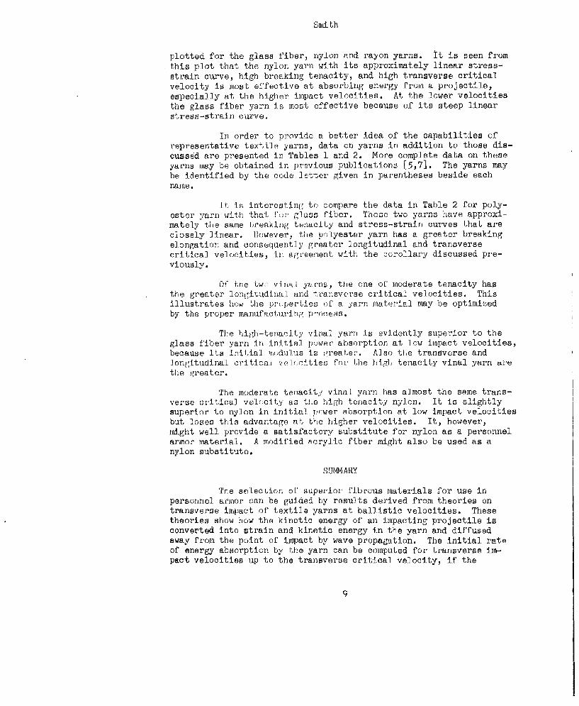
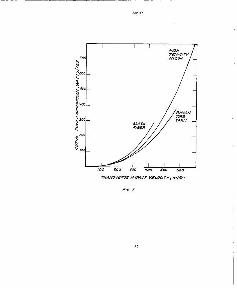
In figure 7 the initial power absorptions (initial rate ofenergy absorption) corresponding to different impact velocities are
8
Smi th
plotted for the glass fiber, nylon and rayon yarns. It is seen fromthis plot that the nylon yarn with its approximately linear stress-strain curve, high breaking tenacity, and high transverse criticalvelocity is most effective at absorbing energy from a projectile,especially at the higher impact velocities. At the lower velocitiesthe glass fiber yarn is most effective because of its steep linearstress-strain curve.
In order to provide a better idea of the capabilities ofrepresentative textile yarns, data on yarns in addition to those dis-cussed are presented in Tables 1 and 2. More complete data on theseyarns may be obtained in previous publications [5,7]. The yarns maybe identified by the code letter given in parentheses beside eachname.
It is interesting to compare the data in Table 2 for poly-. (A ... .ya .w ith ,that ga , f.iber. These two yarns have ........V
mately the same hreaking tenacity and stress-strain curves that areclosely linear. However, the polyester yarn has a greater breakingelongation and consequently greater longitudinal and transversecritical velocities, in a[,L'eement with the corollary discussed pre-viously.
U!" the tws• vin.l yajrns, the one of moderate tenacity hasthe greater longitudinal and transverse critical velocities. Thisillustrates how the pr':perties of a yarn mraterial may be optimizedby the proper manufacturing p'ocess.
The high-tenacity vinal. yarn is evidently superior to theglass fiber yarn in initial power absorption at low impact velocities,because its initial ,modulus is ;,reater. Also the transverse andlongitudinal critical vollrtties for the higl tenacity vinal yarn arethe greater.
The moderate tenacity vinal yarn has almost the same trans-verse critical velocity as the high tenacity nylon. It is slightlysuperior to nylon in initial r.,wer absorption at low impact velocitiesbut loses this advantage at the higher velocities. It, however,might well provide a satisfactory substitute for nylon as a personnelarmor material. A modified acrylic fiber might also be used as anylon substitute.
SUMMARY
The seLection of superior fibrous materials for use inpersonnel armor can be guided by results derived from theories ontransverse impact of' textile yarns at ballistic velocities. Thesetheories show how the kinetic energy of an impacting projectile isconverted into strain and kinetic energy in the yarn and diffusedaway from the point of impact by wave propagation. The initial rateof energy absorption by the yarn can be computed for transverse im-pact velocities up to the transverse critical velocity, if the
9
Smith
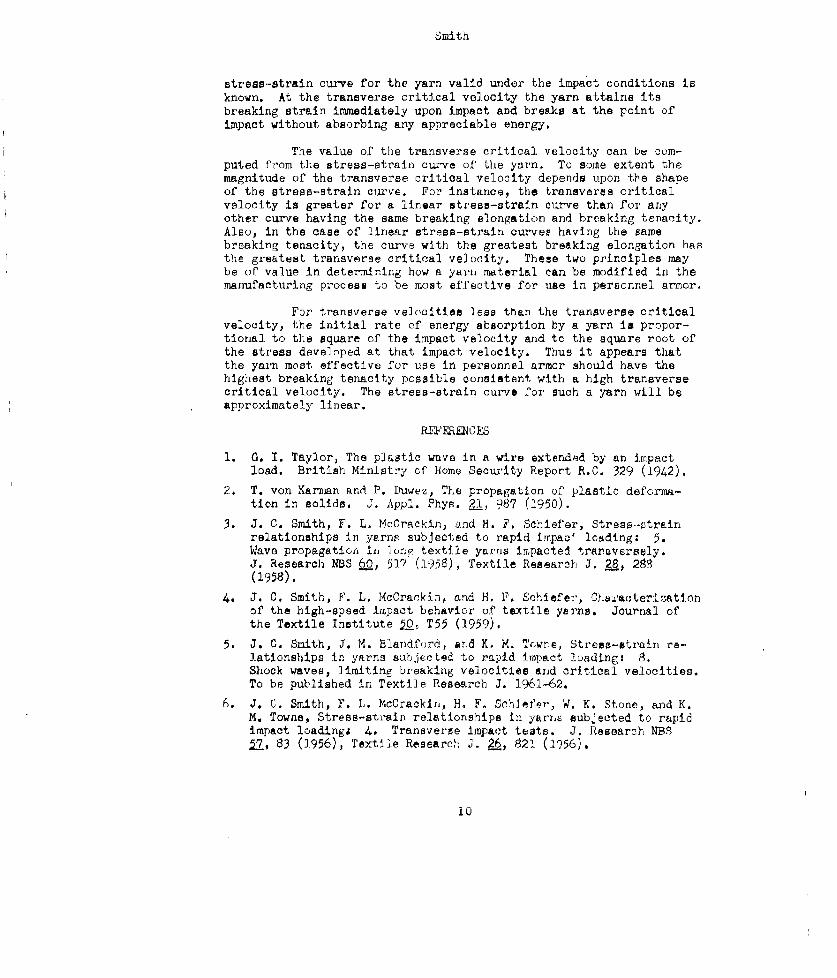
stress-strain curve for the yarn valid under the impact conditions isknown. At the transverse critical velocity the yarn attains itsbreaking strain immediately upon impact and breaks at the point ofimpact without absorbing any appreciable energy.
The value of the transverse critical velocity can be com-puted from the stress-strain curve of the yarn. To some extent themagnitude of the transverse critical velocity depends upon the shapeof the stress-strain curve. For instance, the transverse criticalvelocity is greater for a linear stress-strain curve than for anyother curve having the same breaking elongation and breaking tenacity.Also, in the case of linear stress-strain curves having Lhe samebreaking tenacity, the curve with the greatest breaking elongation hasthe greatest transverse critical velocity. These two principles maybe of value in determining how a yarn, material can be modified in themanufacturing process to be most effective for use in personnel armor.
For transverse velocities less than the transverse criticalvelocity, the initial rate of energy absorption by a yarn is propor-tional to the square of the impact velocity and to the square root ofthe stress developed at that impact velocity. Thus it appears thatthe yarn most effective for use in personnel armor should have thehighest breaking tenacity possible consistent with a high transversecritical velocity. The stress-strain curve for such a yarn will beapproximately linear.
1. G. I. Taylor, The plastic wave in a wire extended by an impactload. British Ministry of Home Security Report R.C. 329 (1942).
2. T. von Karrian and P. Duwez, The propagation of plastic deforma-tion in solids, J. Appl. Phys. 21, 987 (1950).
3. J. C. Smith, F. L. McCrackin, and H. F. Schiefer, Stress-vtrainrelationships in yarns subjected to rapid impao' loading: 5.Wave propagation i0, lol) textile yarns impacted trareversely.J. Research NBS LO, 517 (1958), Textile Research J. Z8, 2(1958).
U_ 8
4. J. C. Smith, F. L. McCrarkin, and H. F. Schiefer, Cha.acterizationof the high-speed impact behavior of textile yarns. JournAl ofthe Textile Institute ý_O T55 (1959).
5. J. C. Smith, J. X. Blandford, and K. M. Tcwne, Stress-strain re-lationships in yarns sabjected to rapid impact loading: 8.Shock waves, limiting breaking velocitlee and critical velocities.To be published in Textile Research J. 1961-62.
6. J. C. Smith, F. L. McCrackin, H. F. Schlfer, W. K. Stone, and K.M. Towns, Stress-strain relationships in yarr-s subjected to rapidimpact loadingi 4. Transverse impact teats. J. Research NBS17, 83 (J.956), Textile Research J. 26, 821 (W956).
i0
Smith
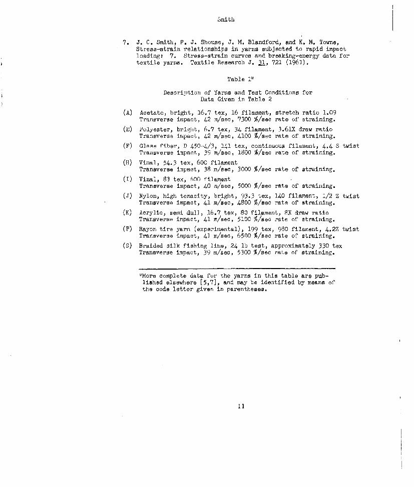
7. J. C. Smith, P. J. Shouae, J. M. Blandford, and K. M. Towne,Stress-strain relationships in yarns subjected to rapid impactloading: 7. Stress-strain curves and breaking-energy data fortextile yarns. Textile Research J. 31, 721 (1961).
Table 1*
Description of Yarns and Test Conditions forData Given in Table 2
(A) Acetate, bright, 16.7 tex, 16 filament, stretch ratio 1.09Transverse impact, 42 m/sec, 7300 %/see rate of straining.
(E) Polyester, bright, 6.7 tex, 34 filament, 3.61X draw ratioTransverse impacL, 42 m/sec, 4100 %/see rate of straining.
(F) Giap fihp.. P) D 450-4/3, 141 tex, continuous filajunt, 4.4 S twistTransverse impact, 39 m/sec, 1800 %/seo rate of straining.
(H) Vinal, 54.3 tex, 600 filamentTransverse impact, 38 m/see, 3000 %/sec rate of straining.
(I) Vinal, 83 tex, 600 filamentTransverse impact, 40 mi/sec, 5000 %/seo rate of straining.
(J) Nylon, high tenacity, bright, 93.3 tex, 140 filament, 1/2 Z twistTransverse impact, 41 m/see, 4800 %/see rate of straining.
(K) Acrylic, semi dull, 16.7 tex, 80 filament, 8X draw ratioTransverse impact, 41 r/see, 5100 %/see rate of straining.
(P) Rayon tire yarn (experimental), 199 tex, 980 filament, 4.2Z twistTransverse impact, 41 m/sec, 6500 %/see rate of straining.
(S) Braided silk fishing line, 24 lb test, approximately 330 texTransverse impact, 39 m/see, 5300 %/see rate of straining.
*More complete data for the yarns in this table are pub-lished elsewhere [5,7], and may be identified by means ofthe code letter given in parentheses.
11
Smith
4Pd ) 0 (0Cc h (\ > Lr\ LW\ 14 0.-r..4 Q U -t 't*N (
1) C-- E- to N CI- -~ 0
U2+'ý0~ m1- W\ -4 to\ f '0 '.0 4") IA\ H
00
E.-4 C) ~ -) ( V 0 ~ t ' ' -4)
.,- 1. 4 ) Ll H 0 O4 ) 40n(1.~ l C 1 CI N C
640 ý4 4
>11
T) N.f.-0 CC) 20 r-i C) 0' - S -4 0 \ 4
w~ 40 0 t 0 O V~ -
*-) 4- - O C\ f H 0 G 7o) 0 04
w' ,O 00
H a) U31.x
-H -H a C 0 0 0 n) C.) 0 0 p -S .- Q4-3 ) l AW C) ,-'0 * C) NV U\ C), -P'HqI-Iý frOf.. ~ 0 -1 C- H~ C) VIA -4 U)3
fr -E- X bOO)4-,
'H .- '0 :lb'
4-)4
'1) V-4
+) Li) USL
U) 4-).0) W) .
11ro 0)b ti t$4i 03
ca 0
4-)4 a) C) .)H H 2
4-) H) ,C, -L 0p- 4 4 l cZ
C~ fl C% C Cs N C, Cs C
12 wP
APPINDIX
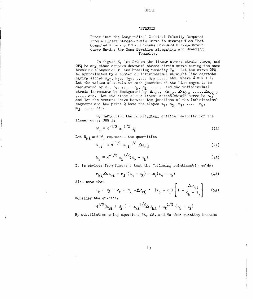
Proof That the Longitudinal Critical Velocity ComputedFrom a Linear Stress-Strain Curve is Greater Than ThatComputed From any Other Concave Downward Stress-StrainCurve Having the Same Breaking Elongation and Breaking
Tenacity.
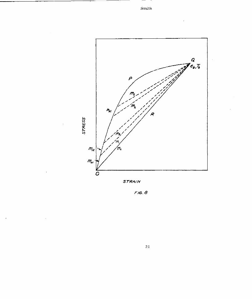
In figure 8, let ORQ be the linear stress-strain curve, andOPQ be any other concave downward stress-strain curve having the samebreaking elongation Eb and breaking tenacity Tb. Let the curve OPQbe approximated by a nulmber oF infinitesimal straight line segmentshaving slopes mi], m1 2 , m2 3 , . . . . . mkt ..... etc. where Z " k + 1.Let the values oC tLrain at each junction of the line segments bedesignated by &-, .. ..... nk, i, ...... and the infinitesimalstrain incremorits be designatod by &Eol, •A 1 2 , !k23." ,.......k I
.etc. Let ti.e slope of the linear stress-strain curve be me,and let the secants drawn between the junctions of the infinitesimalsegments and the point Q have the slopes m, im2 , m3' . . . . . mk,m. ..... etc.
By definition the ]onrgitudinal critical velocity for thelinear curve ORQ is
W= M-/2 1/2(A)
Let Wk and Wk represent. the quantities
W =l M-I/2 4I4'2 F-kX (2A)
W. M-I' 1 1/2(% _ -) (DA)
It is obvious from Cigure 8 that the following relationship hnlds:
mLA%• + MS (-b - EI) =m(% - ab ) (4A)
Also note that
E - l % k- Ak = Ed- 1 (5A)Consider the quantity I
Mi2(Wk. + WA ) = l/2A + m•l/2 ( -
By substitution u"sing equations 3A, 4A, and 5A this quantity becomes
13
Smith
M1/2(Wu + wA) = M1/2AR'2 -
+ 1/2 MM 1/2[ ___/2F
After an expansion in which only linear terms are retained, thisquantity becomes
MJ/2Wk + 1) 2
I Fl/2( - 1Q - i (kI +) &'k
7 /2 A C + Mj/2 ., I 1/2 .A I A.21 -111 k 2 ~~ 1r A/~
So that
M12(k - WkI - WI " + tMk 1/ - ~t/] k (6A)
iL is obvious from figure 8 that ec that NX in
equation (6A) can be replaced by pmk, where p ia a number greater
than unity. The right hax'd side of equation (6A) thus becomes
I(p + 1) p/2]r J . which is always p,,zitve.. Therefore
Wk -W k> 0 (7A)
I- n is the number of infinitesimal se.ments into which thecurve OPQ is divided, ther from equation (7A)
2 (Wr -(Wk W(A)k=O
Note, however, that
n
w = E(Wk - W, (9A)
k=O
So that equation (SA) beoomesn
wo>• W kA (-IOA)
14
Smith
As the number of segments becomes infinite and the length of eachsegment approaches zero, equation (iOA) still holds so that
w° > lim w kk (11A)
k=On
By definition, lim w kL is the longitudinal critical velocity
for the curve OPQ, so the theorem has been proved.
15
Smith
I-IQ
16
Srn-Ath
,r/d.J SrRA/IV *lSrR1A3vr/eW ALOMA' ~fAIMAAW/
srqrs-rA/// URVr
17
Smith
#4' Y4 ON70 "AS -I0
60-
10-
dr a / f /# 1* .6 /8 zo 22
57.AI, P~qcetvr
PfG. 5*
Smith
80-H6
70-t
/o /
50
RAAYON7RE
YAR30
S20-/
/00 R00 t00 "~0 $00 co0
7T1ANvsiER5E/m.pAcr Vl-oClOCry, 'W/S-c.
F16. 6
19
Smith
700- )NYZON
6500
ý:,oo
RAON
IAJ 300 YARIVGLASS
/00-
/00 200 J00 y'oo Soo 800
M'ANAS VR-SE /A4R'Cr Ve4L0C/T)Y, M1/S-C
6I. 7'
20
Smith
Q
-M,
- -
Fl.-
2/1
,,-2,
//
0
Sr7RAI/N
P1.
1JINCLASS IF I ii)
DYNAMTC BEHAVIOR OF TEXTILE FIBERS ANDSTRUCTURES AS RELATED TO PERSONIEL ARMOR
Henry M. MorganFabric Research Laboratories, Inc.
Dedharn, Massachusetts
,Nuw wish KLH Research and Development Corp.
Abstract
Fibers made from linear polymers have been shown to beimportant materials for personnel armor. The useful physicalproperties of fibers, i.e., strength, elongation, modulus, derivefrom their molecular structure. In turn, the useful properties ofyarns and fabrics derive from the manner in which the fibers are puttogether. All these properties are also dependent upon the conditionsof measurement and use. Textile fibers and structures studied atdynamic and "impact" conditions will be discussed with reference totheir use as personnel armor.
Dr. Morgan's manuscript has not been submitted.
UNCLASSIFIED
22
A THEORETICAL STUDY OF PENETRATION AND RESIDUAL
PROJECTILE VELOCITIES
L.E. FagelsoAmerican Machine & Foundry Co.
Niles, Illinois
1. 0 INTRODUCTIONThe design of light personnel armor is greatly aided by the
knowledge of how and when a plate fractures under impact stress.Adequate qualitative and quantitative information for prediction ofthreshold impact velocities for failure, dependence of punchout andspall masses and velocities on material parameters, residual bulletvelocities and energy absorption within the plate are necessary toguide the practical. engineer on his quest for improved armor.
The description of the penetration of a plate by a projectileis an intimate intermingling of several theoretical descriptions.Several basic physical mechanisms, each of which may be quitecomplicated and involved, occur simultaneously or successively in
the course of the deformation.
This paper presents the successive application of some of thephysical theories to obtain a theoretical prediction of the residualvelocity of the projectile and the threshold impact velocity forpenetration. A uniified theoretical approach to this problem,rather than an empirical or semi-empirical approach is given. Amost obvious advantage of this approach is that if reasonable corre-lation to experimental data is obtained, the effect of the variationof individual material parameters may be quickly evaluated.
The basic sequence of physical events upon impact are first, astress wave which is composed of elastic and non-elastic parts, in-cluding plastic flow, is propagated into the plates and, second,fracture patterns are produced in reaction to this transient stress.Simultaneously, a stress wave is propagated backwards into the pro-jectile.
A detailed study of the propEgation of the non-elastic stresswave under Impact loads was made utilizing the theory of dislocation
23
Fugelso
movement under stress.(2,4 )
Plastic flow takes time to occur. If the stress wave Is heldfor a very short period, the total relaxation of stress due to the
flow and the added displacements are negligible. If the load dur-ation is a microsecond, an error about 3% in the displacement is in-
troduced.
For the impact velocity of interest the second order terms inthe elastic stress-strain curve are small. An error of about 8% at
4500'/see impact for the case of an aluminum bulet striking an alu-minum plate is introduced by neglecting them. 3 ) 'However, the neg-
lect of these terms allows a detailed picture of the orientation ofstresses in the plate to be readily calculated. This increase inphysical insight more than makes up for the quantitative error in-troduced. Thus, a l•inear elastic model for the propagation of thestress wave is chosen.
One of three major patterns of fracture occur when a projectileimpacts a plate. The first pattern of fracture is the spall whichis caused by the reflection of a tensile stress wave from the backsurface. The second type of fracture is failure in radial tension.This pattern occurs when the stress wave impulse is long comparedwith the thickness uf the plate.
The third type of fracture, which is the only fracture consid-ered in this paper, is breakup of material directly under the pro-jectile, which is caused by the direct stress wave. A nwriad oftiny fissures are formed In this region, reducing the material there
to a powder and scoopiýng out a large cavity.
A model for fracture in compression has been derived from thetheory of dislocation movement under stress.(3) The fracture processis assumed to consist of three steps: initiation, growth and pro-pagation. The time dependence of the mlcromechanism, i.e., the
movement of dislocations through the medium, is taken as the rate
determining step for high loading rates.
The two models that will be applied are:1 Linear elastic stress wave propagation
2 Fracture in compression
The details of either step are still somewhat complicated, evenwith the sweeping simplifications already introduced. The basic re-
sults for each individual component will be discussed and then thetwo physical processes will be combined to evaluate Several para-meters of interest.
A short synopslb of the basic results is presented in the next
two sections. Only the results of more elaborate calculations are
reported here. For details the reader is referenced to ref. (3 )
24
Fugelso
2.0 ELASTIC STRESS WAVEWhen a projectile strikes a plate, a series of stress waves are
propagated in both the plate and the projectile. If cylindrical
symmetry of the plate and projectile is assumed, i.e., normal inci.1)dence, the equations of motion are both the projectile and plate.
or +OTrz ar - a r
3r kz r t_,2pT rZ p0 p S
6 TPz z z z6r 6zt
X,ji Lame'- Constanrts
c, density
S--XA + 2,.
0 +z
o -- .A + x. --
Qu , 1.1. Ou zA= + + -
Formal integral solutiog for the steesses and displace-ments in the plate are
u e f d s f ' . . . .' S _S 2-tri 31, 0 2p e(ý,s)
[e + FS2 -mz -n,,z
[(j + .2) emZ -mne J (•r)d•
25Best Available Copy
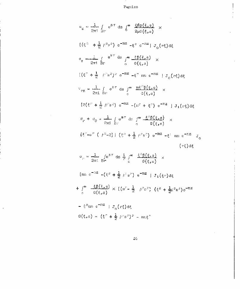
rugel so
27ri Br 6 2piG(~
W, + ) 1mz n
,~~~.t ftiC) o]J (rý)dý
cy e s27iBr 0 G(~s
[~"+ 1 s 2 )2 e-mz mn eflz I J0 (rl'~dý
T f er r ds fxmj(,) >2711 Br 0 (~o
[2~'+,~ s)e~iZ- (n2 + ej J j (rý)dý
ar +a =y 0 L f e S dc s f ___ x27r1 El" 0
[a-2 f' 2 -2) ] (t; + 3~ ~ 2 emz-i' mn e- J
fesT~(~ dsf ILE
27Ti Br'a G ,)
[cm~(ý +n (- +1m m
- 'u- a-riz J (ýd
G(,) (' + . fs)2-mný
2
Fugelso
n 2 2 #s+ •o 23 + 21),
nX +
ef - ,T 7 dU 1-1 p(r,T) Jo(rý) dr0
This is the transform of the pressure on the surface z=O. Simi-lar equations are available for the bullet.
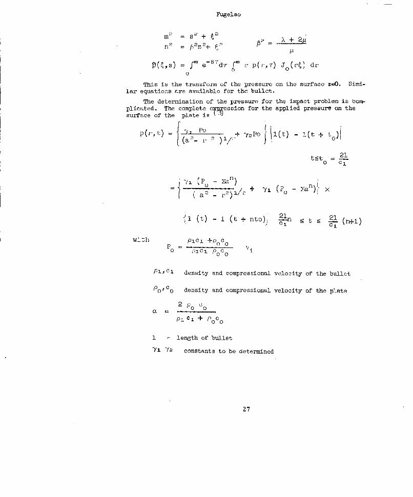
The determination of the pressure for the impact problem is tom-plicated. The complete eppession for the applied pressure on thesurface of the plate Is T3)
p(P,t) = P+ "yPo l(t) - i(t + t[ (a 2- 1 " 2• 0 "
t~gt = 20 c
(i CP0 - 71l)
a2 -+X
j1 (t 1 (t + to)., 2-n1 --t 9 n1(+)
with Pic 1 +PoCo
Po P-cl PoCo
Pi ,C1 density and compressional velocity of the bullet
Po -ICo density and compressional velocity of the plate
2 p 0C0
P1. CI + P 0C
1 length of bullet
'Yi Y2 constants to be determined
27
Fugel so
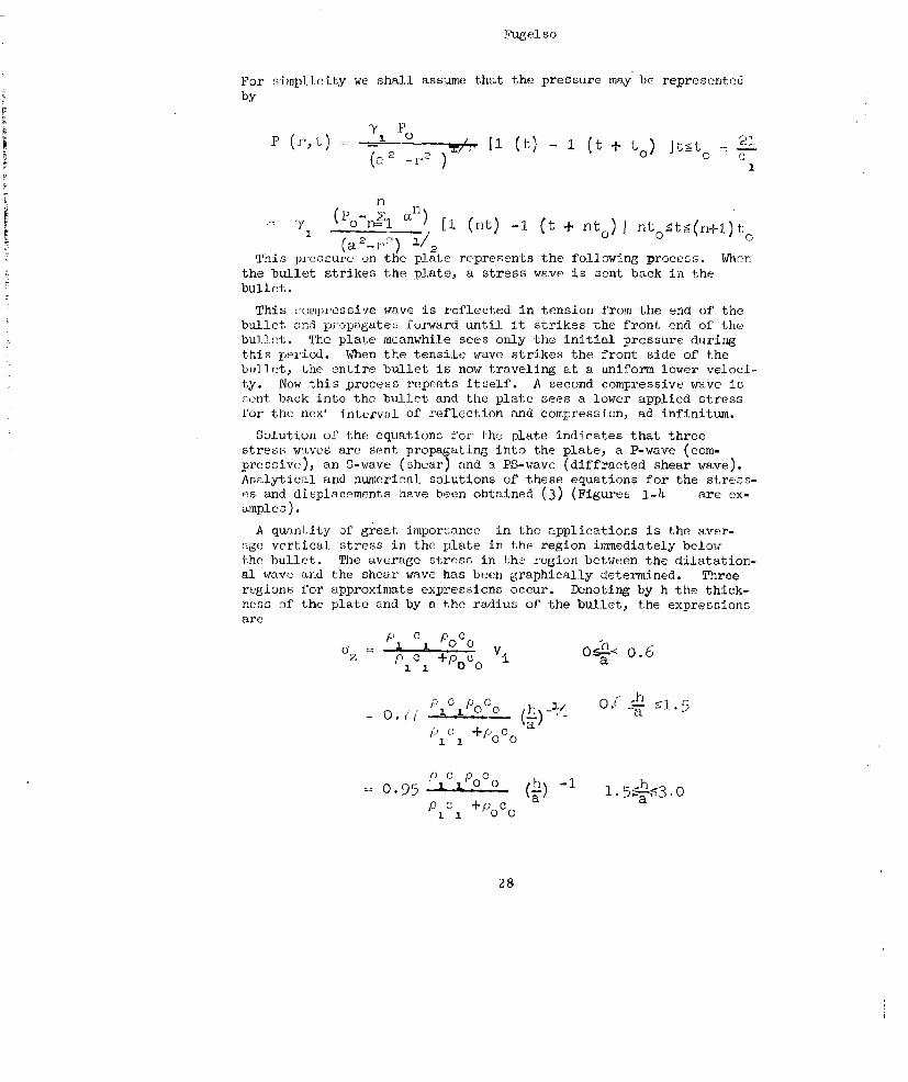
For simplicity we shall assume that the pressure may be representedby
7 Po
P2 27) 11 1 (t + to) (tr<t 9.1(a• _r )•/ 0 •
n-)__________ [
(1 o 0 ) a I (nt) -1 (t + t.) n0o
(a 2 -V) /2 n~t(~~This pressure on the plate represents the following process. When
the bullet strikes the plate, a stress wave is sent back in thebullet.
This compressive wave is reflected in tension from the end of thebullet and propagates forward until it strikes the front end of thebullet. The plate meanwhile sees only the initial pressure duringthis period. When the tensile wave strikes the front side of thebullet, the entire bullet is now traveling at a uniform lower veloci-ty. Now this process repeats itself. A second compressive wave issent back into the bullet and the plate sees a lower applied stressfor the nex4 intervul of reflection and compression, ad infinitum.
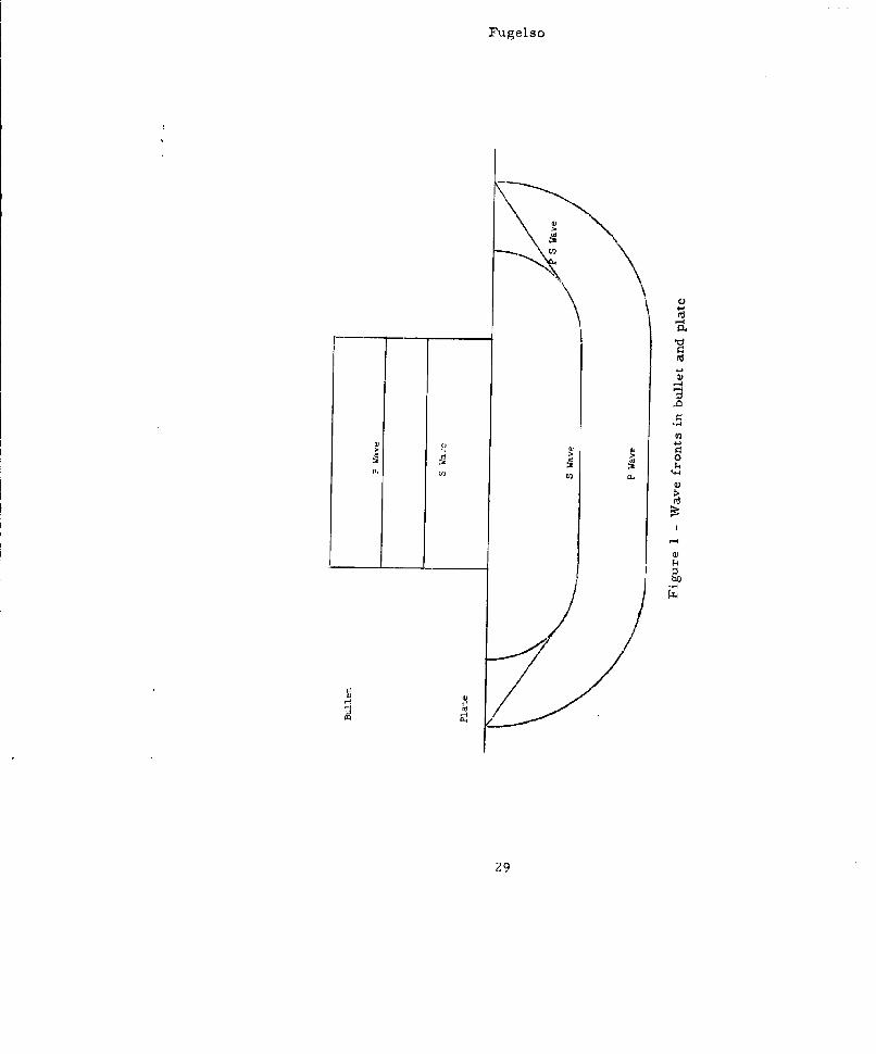
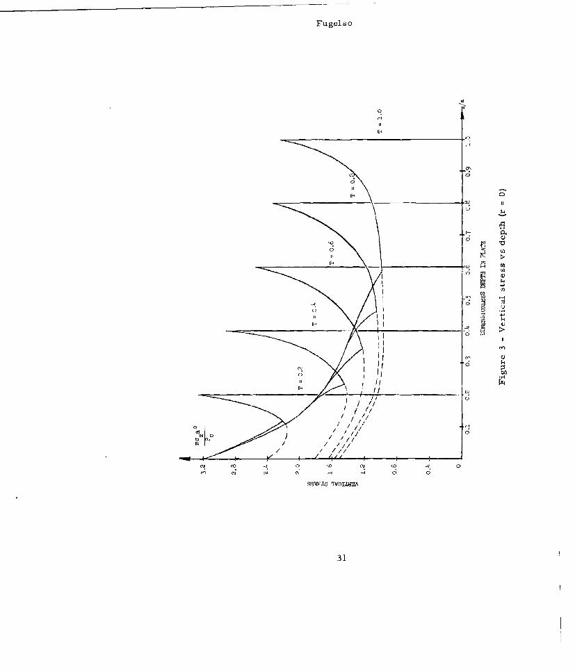
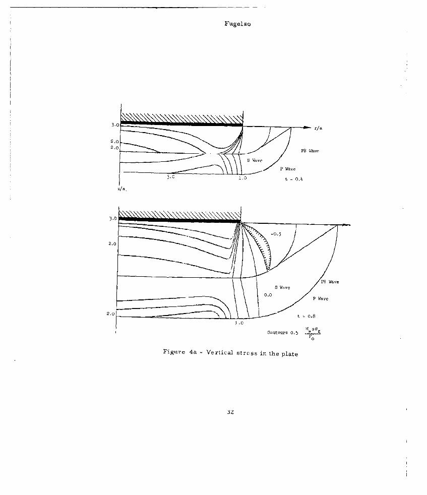
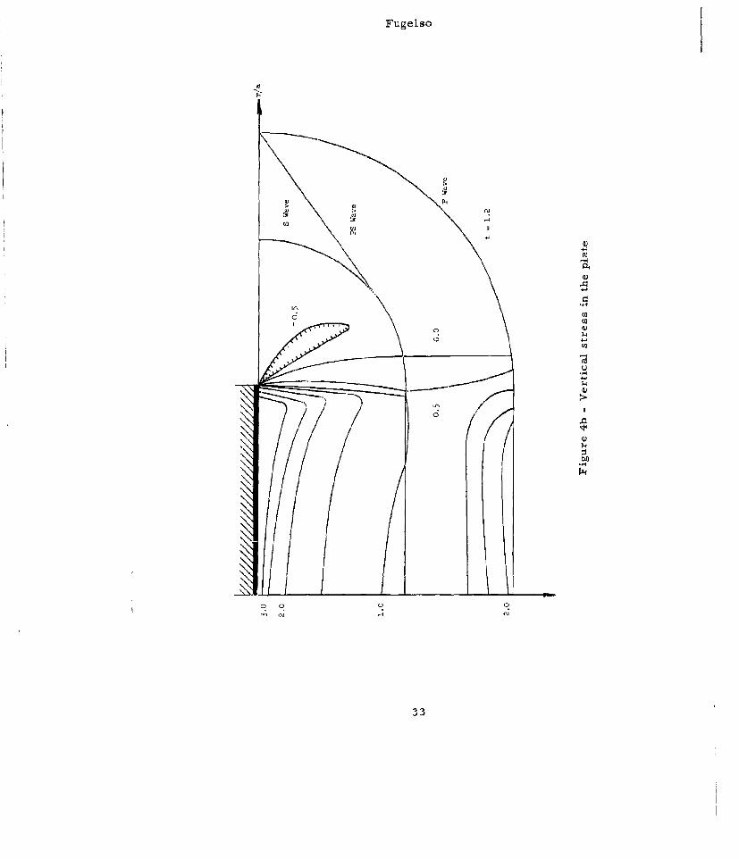
Solution of the equations for thu plate indicates that threestress waves are sent propagating into the plate, a P-wave (com-pressive), an S-wave (shear) and a PS-wave (diffracted shear wave).Analytical and numerical solutions of these equations for the stress-es and displacements have been obtained (3) (Figures 1-4 are ex-amples).
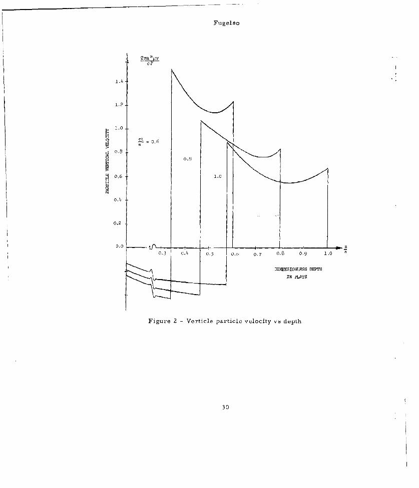
A quantity of great importance in the applications is the aver-age vertical stress in the plate in the region immediately belowthe bullet. The average stress in the region between the dilatation-al wave and the shear wave has been graphically determined. Threeregions for approximate expressions occur. Denoting by h the thick-ness of the plate and by a the radius of the bullet, the expressionsare
=" p " P0c° Vi 0!_51 O 6z +"1
p 0 P 0Z PC Ch 0 a
+0 +000 aa/1 C I+P" O C0
28
Fu gel so
4,
'4
U)
-I0..
U)-4
010) 4,
0) 01 0
4. 10) c,�U)
0))
I-'
40 4'
0)
4..
29
Fugelso
oP
1.4
1,2,
1.0
Set = .6
C. 0.0
o.6 1.0
o.4
0.2
0.2
0.3 C.A 0.5 0.(, 0.7 0.8 0,9 1,0
DIMENSIONLESS DEPT'HIN PLATE
Figure 2 - Verticle particle velocity vs depth
30
Fugelso
El
100
W 1 4.11
Cý C9 ý CFC~i No
31
Fugel so
3.0 3.0
2/.0
2,0P Wa Wav
0,0 Wave PWv
3_____.0 t = 0. 8
z/1.0
-0tor,5 5 .~22.00
?igure ~ ~ ~ ~ ~ ~ P 4a-Vetclavee nte lt
S av
Fugelso
'-4
334

Fugelso
The first region corresponds to that region in the plate wherethe vertical wave is virtually a plane wave. In the second region,the geometrical dispersion of the stress wave has moderate influence.Geometrical dispersion becomes predominate in the third region.
34
Fugelso
3.0 FRACTU CRITERIAFracture occurs under transient stress when a state of stress
is maintained for a specific length of time. The time to fracture isdependent on the octohedral shear stress and the mean stress. Ifthe mean stress is compressive as will be the case for the outgoingstress waves in the plate, the rate determining mechanism is the move-ment of dislocation. By considering a simplified model of dislo-
cation motion under stress (3) (4), an exponential dependence of thetime to fracture is found
t AE -T 7O
t 0O
O T-T7V,0 e- 0
where T is maximum shear stress
t is the time to fracturet is a material constant0
E is the activation energy for a dislocation to move0
k is Boltzmann's constantT is the absolute temperatureTo^Y, T are material constants
For this appl cation the stress durations are of the order of mag-nitude of 10" sec, so that only times to fracture shorter than 10-6
sec. need be considered. This occurs where high octohedral shearstresses are formed. If the pattern of stresses in the plate areknown, the expression may be converted to an expression in the ver-tical stress
ot AEz " Yz eol
35
Fugelso
4.0 CRITICAL VELOCITIES FOR PENETRATION AND RESIDUAL BULLETVWLOCITIESThe critical impact velocity for penetration and the residual
velocities after penetration of the bullet and of the plug will becalculated. After the impact, a sequence of stress waves are sentforth into the plale. The magnitude of these waves is determined bythe velocity of impact and the materials of the plate and projectile.Thereafter, the propagation of the stress waves in the plate deter-mines the subsequent behavior, i.e. the plate tears itself apart.
Numerical solutions of the integrals in Section 2.0 for thestresses in the plate offer en insight into the break-up of the plateunder impact stress. There arc three waves that are propagated intothe plate
1. A coiupreuuionwl wave_2. A shear wave
A dqffrp._. ,-t,1 wav
The state of :stress be tweun the P wave front and the S wave is tran-sient, but the state of dtress behind the shear front is very nearlythe static stress slate. Recall the behavior of the stresses in theregion directly under th, bullrt. as given in Section 2.0. Tig3 showsthe variation of the vertical stress with plate depth directly under[he bullet center. Figures &L and 41h show contours of the vertlcalstress with position for vnrious times. Compared with the staticsolution (Figurer 5 ) the sta.te of stress beneath the bullet end be-hind the shear wave front is essentially the static solution.
Using this critueria the octuhedral shear stress behind the sh-ear wave , 5 , may be rapidly calculated. (Figure; (, ). Apply nowthe derived criteria t'ar r:,cture, to occur. This criticnl octahedralshear stress for fracture is shown as a, function of position forseveral a.pplired siress,- (Figur'.' '5. )
The mate-rial in this region between the shear front and thecritical shear str¢,ss is presumed to be completely fractured, there-by reduced to powder. This fracture pnttern will reduce the sizeof the punch out. For higher impact velocitires the whole region be-hind the shear wave front is fractured,
If the outer rim of' this critical octahedral shear stress isexamined, the increase of the volume of material pulverized, orequivalently weight loss of the plate, may be calculated graphically.This solution is shown graphically for two plate thicknesses in Fig.11. The use, of this graph is self evident.
The locus of the octahedral shear stress between the compressionwave front and the shear wave front that satisfies the fracture cri-teria is directly under the rim of the bullet. The stress patternin this region will determine whether or not the plug will separateand therefore, whether penetration will occur.
36
Fugelso
0.9
0.9 )0.8
o.6
0.5.
0.3
0.1/
z/eContours 0.1iY
Figure 5 - Static vertiral stress in plate
37
Fugelso
0.10 a.o6n/a
0.12
o.14
0.16
0.17
0.17
0.16
0.12
0.08
0.004
Contours 0.02 _z
Figure 6 - Octahedral shear stress
38
Fugelso
0 1-.5
-. T 0. 5', I
i I I P 1
T
r1.7
zI EI
S ave T 1.0
/ e,
/ P
a-- T =0.58
/
Figure 7 - Pulverized regions in plate at various times
39
Fugelso
1.5 2.0
a T 1.D
0.5 PO
.77
Wave - .8
P Wave
0.40
1.0
S Wave
1.5
2.0. P Wav: Et T- 2.
P
Figure 8 -Pulverized regions in plate at various timnes
40
Fugelso
00
0 Of
A 41
• , ,
E-ojoj-4O n o
41 - .1
401
Fugelso
1.5 2.0 2.5 3.0
II
II
//
.0.5
P Wave // ct/ =T=2.0
/ a
2.5. ? P
Fu 1s te p36
Figure 10 -Pulverized regions in the plate
4Z
Fugelso
(3
-4
0
0
'I
606
446
Fugel so
This will give the v5 0 point or the critical impact velocity
for penetration. The calculation of the v 50 point may become quite
involved. To simplify the procedure, the plate thickness to bulletradius ratio will be assumed to be less than 0.6. Then the stresswave that is propagated is virtually constant across the thicknessof the plate. The peak at the compressive wave front is
Po~ +c T1 0
Now the time duration of the lowest possible stress level iscalculated. This will be compared with the time to fracture. Thelowest possible stress that has a time to fracture less than or equalto this applied load time will determine the critical velocity forpenetration.
The region behind the shear front is presumed to be completelyfractured. The total pulverized region is that region behind theshear front at the time the P-wave strikes the back of the plate.The longest sustained stress pulse then has a duration.
t* = (1 .57 0 he
A crack is formed directly under the lip at the shear frontand propagates vertically at 1/5 of the sound speed. When thiscrack reaches thr back surface the plug will separate.
The stress level that is maintained for this longest timeinterval is obtained from t.he graphical solution for the verticalstress and is
az min 0.)13,9, o z (wave ±vont)
"I C c
0.4 36 '0 o v.oo + e
Inserting this value for qz and t* into the equation for time to
fracture and using
t = l0"I ace.10-1
and o0 static compressive yield strength, thp lowest possible
value bf v. for fracture tunder the lip of the bullet is determined.1
The threshold velocity for penetration is then
44
Fugelso
t+ (, ., I, °n rE o
0.436 PoCO o t -
where t , is the time to fracture of the static yield stress (t 1 is
taken to be 10 see.)
Similarly for 0.6 <.h < 1.5 the threshold velocity may be cal--- a -
cuilated. It is t*in
a (3 I- I/+ o0.32/ p 0 , a
Solutions for the critical velocity versus plate thickness forseveral combinations of plate and projectile materials are shownin Figure . The expressions for the variation of average stressgiven on the following page are used for calculating the higherplate thickness ratios. The increase of critical velocity in thelow range is slow. In the thicker plates this increase becomes muchmore rapid. Interpretation and use of this graph is self evident.
The residual projectile and plug velocities after penetrationwill now be calculated.
Assume now that the plate fractures under the rim of the bulletimmediately on arrival of the compressive wave. This assumption de-mands that the impact velocity be sufficiently greater than thethreshold penetration velocity and thus leads to the linear approx-imation for residual velocities at high impact velocities. Theregion of the plate that forms the punch-out is that between the P-wave and S-wave and directly under the bullet.
At this instant, the stress on the cylindrical sides of thepunch=out is relieved and a converging stress wave is generated.The nature of the stress wave is such that after propagation of' thisconverging wave, coupled with the reflected tensile wave from theback surface, the average vertical velocity in the p,,nch-out isindependent of radial position and very nearly equal to twice theBeltrami product oZ= pce for the average vertical stress ot r=O.
Thus a javg) it=0
V =
P C4.5
45
Fugelso
1 000 Titanium Target
o
4)
(st 4130 Steel46 rget
*~5CC
Almnm2024Ta rget
L0 D-5 1.0 1.5 2.
Reduced Thickness
Figure 12 - Variation of critical impact velocity forpenetration as a function of plate thickness(steel bullet)
46
Fugelso
This value has been numerically computed for several plate thickne-sses.
Approximate numerical forms of this average stress are
a Sz A 0 -- 0.6a
• ••-i,° 0-6 4 1,i5z 0 77TA 1, .5
azi 0.95A (h-l 1.5 - h 30za a
where IoCo P
A i 4o c
The reduction in bullet velocity may be computed by consider-ing the stress waves generated in the bullet and is given by theformula
v n C tV 1-i -l 0, 1,2...
2oo 0 c 2L n t 2L n +P + f) (n )
The time that is used in computing these values is the time ittakes the P-wave to reach the back of the plate, since the fracturethere is assumed to occar very rapidly with respect to the pulseduration. Thus
ht =h
C 1
The residual velocities are plotted in Figures 13-18 forvarious combinations of bullet and target materials. To determinethe residual velocities of the plug and projectile, calculate the
rats for the particular problem. Locate h on the abeissaaa
for the particular combination of plate and projectile materials.S~L
Look at the curve parameterised by 1 to determine the residual bullet
velocity. The residual plug velocity is given by the value of the
47
Fugelso
CN
It'0)
GOqK RI-04 -cnps
48 4

Fugelso
Q)
41-
M ' U 01-
4) U ) U)(
00
C) 4 1C.) V
14 P; HI 04
4)9
Fugelso
(a)
cm ILI
Fj Ca
H c
ID-
0) v
cc ~ at
ouo
C; 0
500

Fugelso
It
~41
II - -
0 W
00~4 q~~ '
rd c
~004
511
Fugelso
43 0
0 02
00 0.
u W
H CID
C) 0

Fugelso
V h V- curve at that 7. If the value is greater than L, this in-vivivi
dicates that the bullet is coming through faster than the plug thatit is pushing. In this case, the velocities of both the plug andprojectile are the same and are given by an average value
V* V* V V
V I v P h( P)+ L( VLA- Ii I i,
h+ L
Thirty specific examples are explicitly evaluated for the reductionof bullet vdLocities and punch-out velocities for specific geomet-ries and material combinations (Figure 18 and Table I ).
An examrple for the entire velocity range and the thresholdvelocities is given. The example is carried out for a particularcase of engineering interest. The bullet is steel, diameter o.50cm. and length 0.50 cm.
Three target materials, aluminum 2024 alloy, titanium and steelare chosen so that the mass per unit surface area is constant. Therespective thicknesses ar Al 0.288 cm, Ti 0.172 cm, steel O,10 cm.
This problem is chosen to correspond to a common design pro-blem in personnel armor plates, namely, comparative evaluation ofballistic resistance of different materials with the same totalweight.
The reduction in projectile velocity is made as before, using,however, the time that the crack reaches the back side in theequation for velocity reduction. This is
h h
= L- + 5 (.429)-L = 3.15--c c c c
1 1 1
These results are shown in Table II . The residual bulletvelocities are shown in Figure 19. For this particular exampln,the titanium alloy plate offers the best resistance to penetration.At higher velneities, the redliwtlnn of bullet velocity is very near-ly the same, each plate differing from the others by a very smallpercentage.
53
F'ugelso
00
H 000
CA
HX Cu U
Fugelso
ID G\C HO (0 CC) CO m t r
C; o
00 00 0 0oCý ( 00 OH O
H Q() (Y-% O co L' iC C) -Zlt H- L.\Ho U'\ INOD CC H0 ~- ON Lr\ CO U*\U -A
0 0 ( 0 0 (D C) Cm o.
* -, 0 H
H 4-,
0 -4
::jj r- j- C i -
U)U)W(bU
L) Hj
Fugelso
41 00
I'D
[A A () C'.)Lr(r\
C) ONO
0*0
0. C.)
01
CD
0 0 LCl\
H 0-t
H .41 0 0
4-) 4) 4) i
H- H4 1 0C V CO
W) 4) ) 4(1) 4) I Cl .i) I1 4~) 11 t ~ 4 41 ,-
56
Fugelso
3000
0.10 cm.Fe
*1-. 0. 9 0
A!
-.v 0.12 cm. Ti
.- 0,92 V1
Sv1v 0.86
- i00010.67
0,Q
0
0 32320 1000 2000 3000
Impact Velocity (n1./sec,)
Figure 19 - Residual bullet velocity versus impact velocity
57

Fugelso
5.0 CONCLUSIONSIn the design of light personnel armor to resist or retard
penetration by projectiles, the knowledge of the fracture and sub-
sequent behavior is a necessity. This information is aided by thetheoretical studies of the deformation.
The linear elastic solution is sufficient to describe, to with-in reasonable accuracy, the deformation in a plate due to projectileimpact under the restrictions;
1) The impact velocity is less than 4000'/sec.2) The time duration of the load is less than 50% see.
The contributions of finite strain and plastic deformation inthis regime are not zero, to be sure, but reasonable quantitativeinformation is obtained without considering these effects. At high-er velocities, or with longer impact durations,or with alteration of
material properties, particularly with regard to inelastic deforma-tion, these effects must be included.
Two elementary physical theories have been applied to the pro-blem of penetration of thin plates by impacting projectiles. Thecsetwo mechanisms were the linear elastic stress wave and fractureassociated with the direct stress wave. Despite the obvious limita-tions imposed on the quantitative data by choosing these two approx-imations, reasonable agreement with exnprlmenta! data ic obtained.
The threshold impact velocity for penetration is a function ofseveral parameters, among them the static yield stress, the acousticimpedence of the plate and the thickness of the plate.
The mass of the plug ejected in the penetration process willdecrease in two steps corresponding to two different fractureoccurences. The first reduction in plug size is caused by the pul-verization of material behind the shear wave front of the directstress wave. The second reduction is caused by spall from the stresswaves generated at the side of the plug.
The residual velocities for the projectile and plug for anycombination of materials thickness and are easily calculated.
The dependence of the residual bullet velocity on the platethickness to bullet length has been shown.
Several specific problems occurring in the application ofthis basic analytical work were carried out. Two major conclusionsthat may be reached concerning impact ere as follows.
I. To increase the threshold velocity for fracture, the com-bination of several factors must be maximized. We recall the exp-ressions for the threshold velocity for thin plates
58
Fugelso
t*
T ( P3C + P 00o 0) 0 h -
VI O.43b pop 0c 0 In-.r :•06in ±--
0 °+poco i@t0
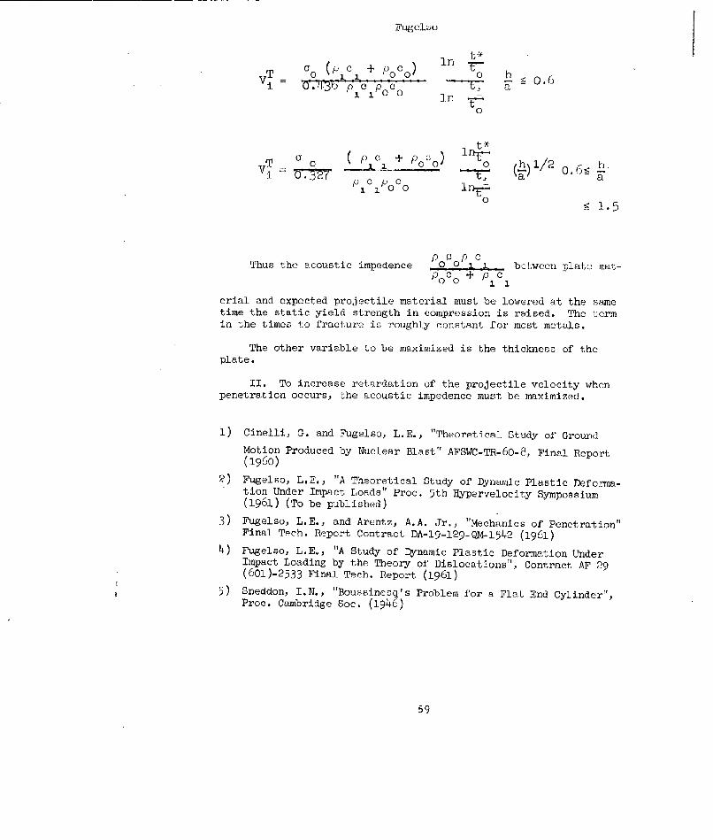
Thus~ th1.ut5 meee •btze paemt
PoCo + P o
erial and expected projectile material must be lowered at the sametime the static yield strength in compression is raised. The termin the times to fracture is roughly constant for most metals.
The other variable to be maximized is the thickness of theplate.
II. To increase retardation of the projectile velocity whenpenetration occurs, the acoustic impedenee must be maximized.
1) Cinelli, G. and Fugelso, L.E., "Theoretical Study of GroundMotion Produced by Nuclear Blast" AFSWC-TR-60-8, Final Report(1960)
2) Fugelso, L.E., "A Theoretical Study of Dynamic Plastic Deforma-tion Under Impact Loads" Proc. 5th Hypervelocity Sympossium(1961) (To be published)
3) Fugelso, L.E., and Arentz, A.A. Jr., "Mechanics of Penetration"Final Tfeh. Report Contract DA-ln%129-Q14-•1542 (196)
4) Fugelso, L.E., "A Study of Dynamic Plastic Deformation UnderImpact Loading by the Theory of Dislocations", Contract AF 29(601)-2533 Final Tech. Report (1961)
5) Sneddon, I.N., "Boussinesq's Problem for a Flat End Cylinder",Proc. Cambridge Soc. (1946)
59
"METHOD FOR OBTAINING YirLD STRE.;SES AT HIGH STRAIN RIATEiS
J. W. CorcoranBeckman & Whitley, Inc.San Carlos, California
Introduc; tien
ýStraun rates observed in armor peenetrtti on experi-ments characteristically have vwlues of the order of io3to 1O4 /sec. While it has been noted thait the propertiesof mnaterials cre altered from their staýtIc test valuesi,very little experiment-1 data is availýble under thesecircumstances. The reason is obvious. Standard testingmachines can be e•,odified to give rates of 102/sec (Manjoinfflbut for greater rates than this new test methods b:ased onimpulses rather than steadily applied forces are necessary.
Test TheoryAn experimental arrangement to achieve this is shown
in Fig. 1. A cylindrical ch-trge is l.-ced on the axis of ahollow cylindrical test slecimen and the intervening spacefilled with wat,,r. Whern the charge is detonated a conicalshock wave moves out radially thru the water and impirts :ini.mpulse to the tea;t material. After the 3hoeck reaches thefree surface a rarefictlon (negative pressure) wave immtediate-ly propagates bact thru the specimen and water. This negativepressure causes cavi tation of the water at the inner surfa:ce!of the specimen effectively isolating- it from the water andit moves outward under its on inertia)l forces. This seiuenceof waves may be observed in Fig. 2, m series of high speedphoLojorajhs taken thru a longitudinal section of such aspec imen.
As the s,, cimen atnves redi:,lly outward it dcvloios atensile hoop stress within itself which acts to decelerate it.The kinetic energy is thereafter absorbed by elastic andplastic defnrmition of the cylinder, From the law of con-servation of energy the velocity i:s given by the formula:
60
Corcoran
C1 C22-V3 Eedc +1 S de 2
0 6
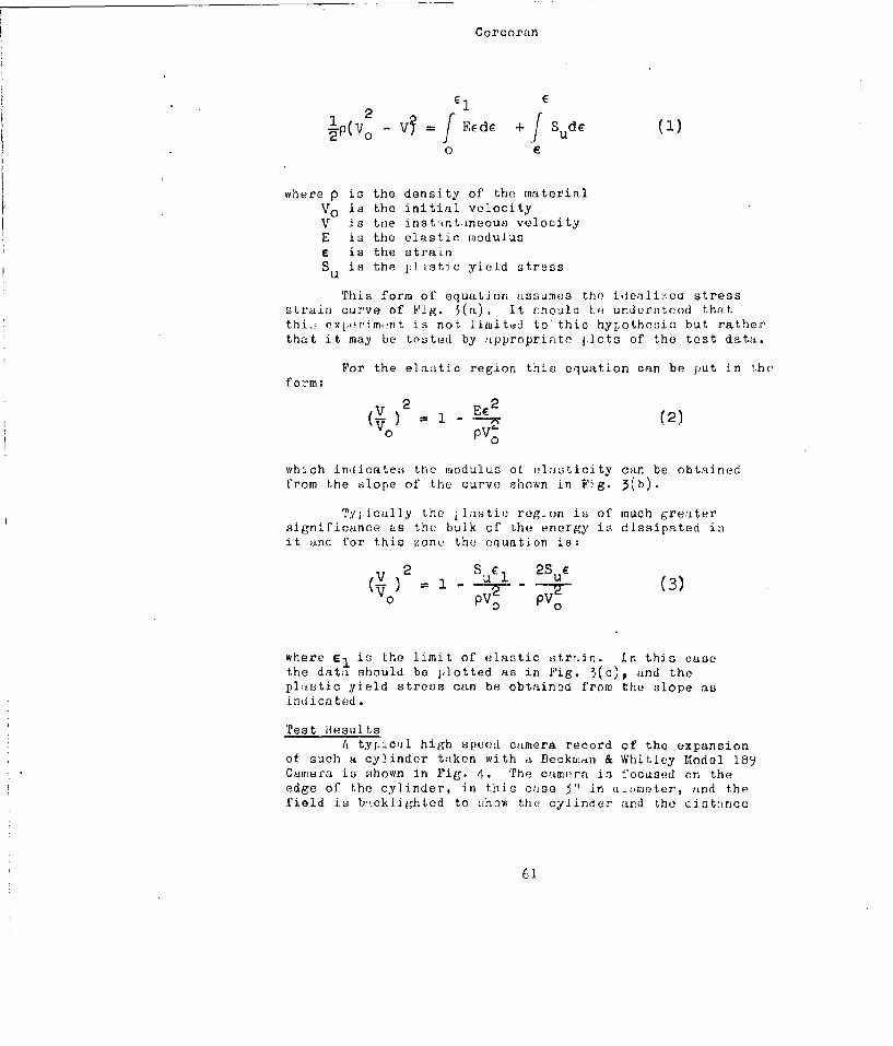
where p is the density of the materialVO is the initial velocityV is toe instintineous velocityE is the elastic moduluse is the strainSu is the j:1istic yield stress
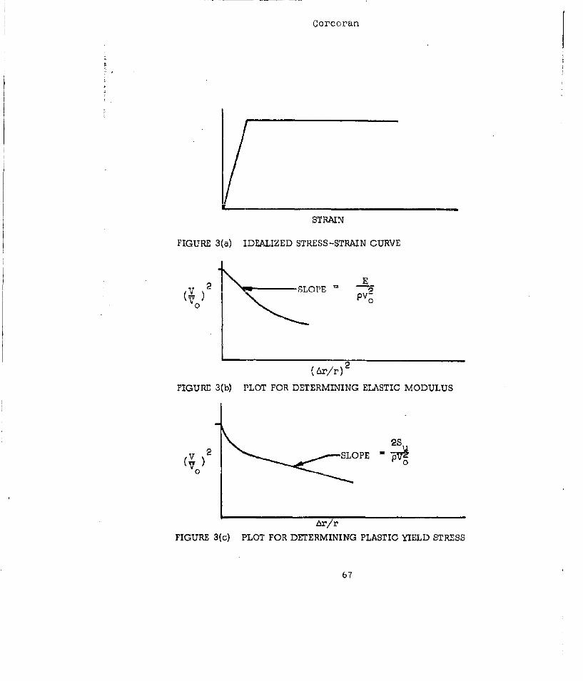
This form or equation assumes the ideali:ced stressstrain curve of Fig. 5(a). It .hould Le understood thatthi:- exjoerim,.t is not limited to this hypothesis, but ratherthat it may be tested by appropriate j[lots of the test data.
For the elai.tic region thi.s equation can be put in theform;
Y E)% (2)
00
which indicates the modulus of elasticity can be obtainedfrom the slope of the curve shown in Fig. 3(b).
Tylically the ilastic region is of much greatersignificance as the bulk of the energy is dissipated init and for this zone the equation is:
2 Su2I 2 SU6Voo pvc Pv0
where el is the limit of elastic str:1 in. In this casethe data should be plotted as in Fig. 3(c), and thepl•stic yield stress can be obtained from the slope asindi cated.
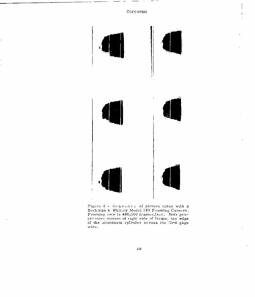
Test HesultsA t~yp.ic:l high speed camera record of the expansion
of such a cylinder taken with a Beckman & Whitley 14odel 189Camera is shown in Fig. 4. The camera is focused on theedge of the cylinder, in this case 3" in d'ýmeter, and thefield is b-tcklighted to show the cylinder and the distance
61
C orcaor an
gage wires which were placed 0. 125 inch apart. Theframing rate was 480,000 frames/aec hence the individualpictures 'Were taken 2.08 sec apart.
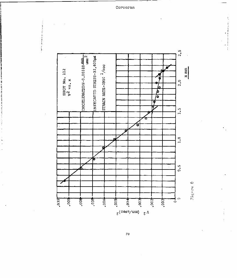
A tyl-ical data plot is given in Fig. 5. The materialwas 2024 T4 Aluminum and a plastic yield stress of' 32.,60(0psi was obtained at a strain rat~e of' 2900/0e0.
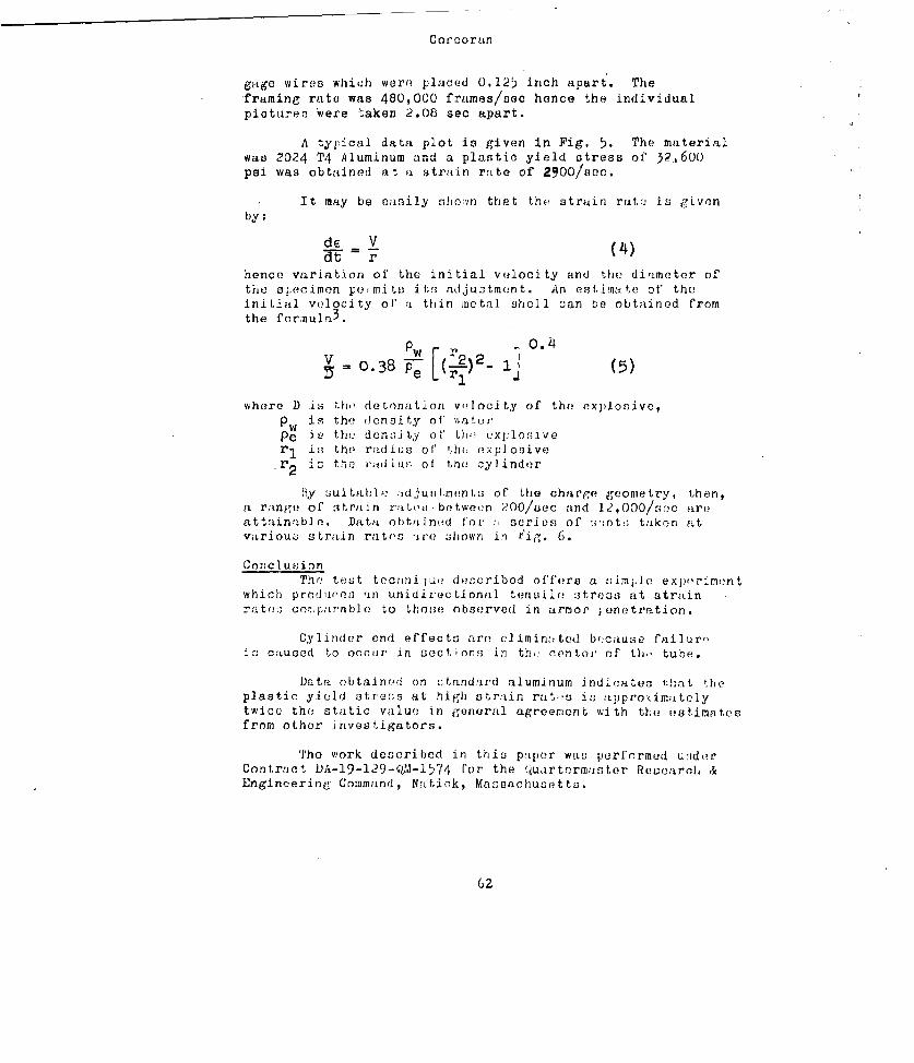
- It may be easily shoevn that the strain ra~is ilv(,nby:
rE (4)hence variation of' the initial velocity and the diameter ofthe al.ecimen per mit" i ts adijuotment. An estimate of theinitial velocity of a thin metal shell oan be obtained fromthe forimula 3 .
V 0.387 ,2)2 0.- - ij (5)
where D is fho detonation volocity of thf! explosive,
PWis the density of' %%aterPe i v t he don.nAty of'U, tin xploo,,veri is the radius of' 'Ah exji osive
isr t h (- ixidiusl of the cyl inder
11y sui table :idjustmvnn t.! of the charge geometry, then,a range of strain r;Lte.; between 200/uec and 12),000/srec aroattainfible. Data obtained for !,series of ,;hotj; taken attvariouo strain rates 'ie howvn in iig. 6.
ConclusionTh(e tEst61 tectrjini w dencribed offers a oiirn.le experimont
which produrns 'in unidiree tionial tensile! otreas at strainrates; col:isirable to those observed in arnmor ; enetration.
Cylinder end effects are eliminzited bn~cause failureýic catused to occurii in see 1 on!' in th,. ceontoiy of LI),' tube..
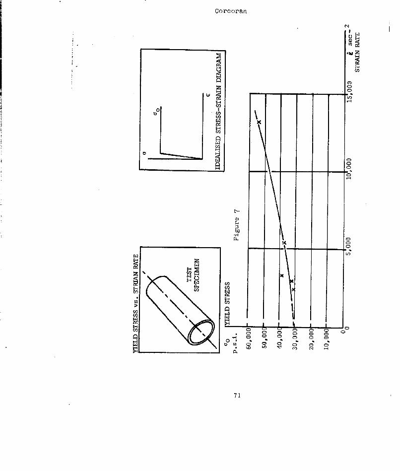
Data obtaineýd on standurd aluminum indicates that theplastic yiceld s trefes at high strain rate!s in; appro-dmrateiytwice the static value! in general agreemnent with the estimatesfrom other investigators.
The work described in thisj paper was performed uede!rContrfict DA-19-129-Qt71-1574 ['or the Qýuartermaster Research &Engincerine Command, Natirk, Massachusetts.
62
Corcoran
Bibliography
1. Bodner, S. R. and Symonds, P. S. "Plastic Deformationsin Impact and Impulsive Loads of Beams" Plasticity,Pergamon Press, pp. 488-500, 1960
2. Manjoine, M. J. "Influence of Rate of Strain andTemperature on Yield Stresses in Mild Steel"J.App.Mech. Vol. 11, pp. 211, 1944
3. Holland, T. E., Final Report, George WashingtonUniversity Research Laboratory, AD 306050, 1959
63
Corcoran
Table of Figures
Fig. 1 Charge Configuration for Producing High StrainRates
Fig. 2 Framing Camera khotograph Showing Shock andRarefaction Waves in a Logitudinal Sectionof Charge
Fig. 3a Idealized Stress-Strain Curvesb Plot for Determining Young's Modulusc P'lot for Determining Plastic Yield Stress
Fig. 4 Framing Camera Photographs of Cylinder ExpansionFig. 5 Plot of Velocity Sqruared vs Distance for 2024
T4 AluminumFig. 6 Plot of' Plastic Yield Stress vs Strain Rate for
2024 T4 Aluminum
64
Corcoran
EXPLOSIVEC HARG E
WATER
Figure 1 - Charge Configuration For Producing High Strain Rates
65
Corc oran
Figure 2- Fr'aming camera picture of shock andrarefaction waves in a longitudinal section ofFigure I.
Corcoran
STRAIN
FIGURE 3(a) IDEALIZED STRESS-STRAIN CURVE
S.2 -SLOPE -pv-(°) 0
(Ar/r) 2
FIGURE 3(b) PLOT FOR DETERMINING ELASTIC MODULUS
2SV 2 SLOPE -v
0
Ar/rFIGURE 3(c) PLOT FOR DETERMINING PLASTIC YIELD STRESS
67
Corc oran
~11 II
Figure 4 - Se q u e n cc of picture taken with a
Beckman & Whitley Model 189 Framing Camera.Framing rate is 480,000 frames/sce. Note pro-gressivc motion of right side of frame, the edgeof the aluminum cylinder across the first gagewire.
68

Corc oran
LIGHT SOURCE
T SPECIMEN
LIGHTINGLENS
SPACED
FRAMING CAME
Figure 5
69
Corcorran
iiOIE
CDNCj '-I
CZ
Cf))
Io > --
00
z0
Illy,
-7z CD•
CD Cl/ C) CD CAC
70
Corcoran
II
00o ,°
ot
C,)D
U)O
E-.i
x
>i '-4
I-I 0
%0
C CD
a,
S0 % 0
71
THE DYNAMIC PROPERTIES OF HIGH TENACITY YVMINS ANDTHEIR RELATIORSHIP TO BALLISTIC RESISTANCE
R. C. Laible
QM R&U CommandNatick , Mass.
Two possible inter-related advantages result from tihestudy of the mechanical properties of textile materials. The firstis that we may predict the usefulness of the material under study forpersonnel armor applications. The second is that the informationgaincd about several different synthetics should allow us to predictthe ideal properties that the material should possess. With thisinformation in the fiber manufacturer's hands, we would be insuredimproved materials.
At last year's symposium, the stress-strain properties ofVinal, a highly oriented polyvinyl alcohol type fiber, were dis-cussed.(l) The high strength and high wo;rk to rupture characteris-tics were pointed out with special emphasis týn the relative cmn-stancy of work to rupture with increasing strain rate. The detailsof this stress-strain work will appear in the September issue of theJournal of Polymer Science and will not be repeated here.(2)Fabrication of the Vinal yarn into fabric and subsequent ballistictesting showed a 5-10% improvement over the standard nylon bodyarmor. The vinal could also be bonded fcýr use as a helmet liner.The future of Vinal in the ballistic program will now depend uponits domestic availability.
The next new material investigated was isotactic polyprc-pylene. (3) Prior to Natta's developments in the field of stere',-specific polymerization, polypropylene was a low melting solid un-suitable for forming fibers of any kind. In contrast, isctacticpolypropylene lends itself to the formation ý,f fibers with excellentmechanical properties and would therefore appear to be a likely can-didate for personnel armor applications.
Experimental Methods
Polypropylene yarn with a crystallinity of 051" and anorientation of about 90% was subjected to stress-strain testing
72
Laible
at many different strain rates encompassing five decades of testing
time. The methods used included the Instron for static tests, sev-
eral pneumatic and pveumatic-'iydraulic systems for intermediate
speeds, the rotating disk method for impact testingý the falling
weight and ballistic methods.
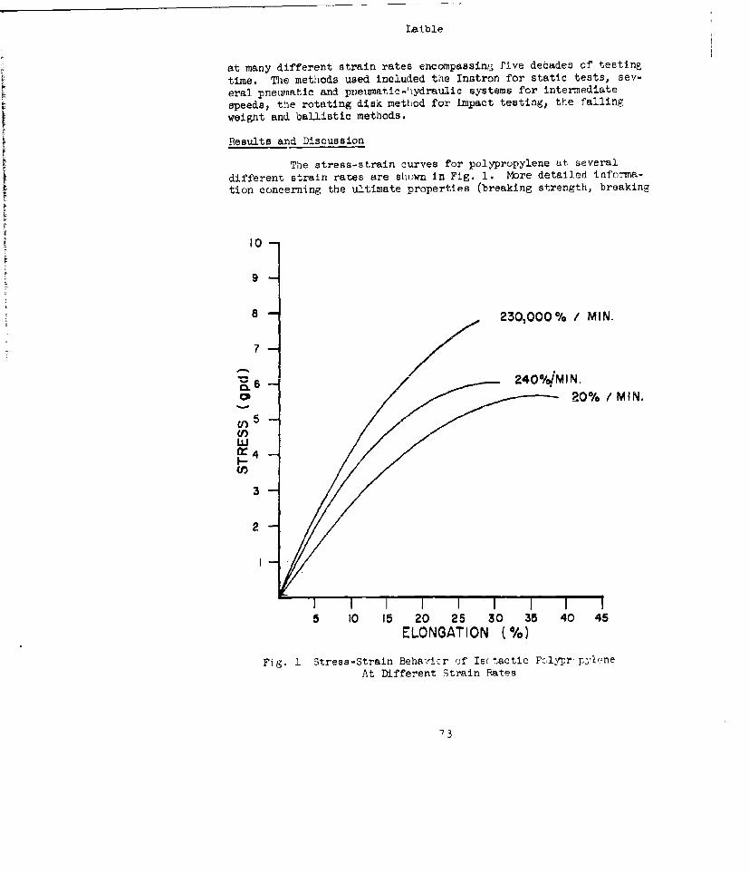
Results and Discussion
The stress-strain curves for polypropylene at several
different strain rates are shown in Fig. 1. More detailed informa-
tion concerning the ultimate properties (breaking strength, breaking
I0
9
8 2-30,000% / MIN.
7
-6 -- 2400/4MIN.
20% / MIN.
CI)Uf)5LiJ
3
2
I I I I I I I5 10 15 20 25 30 35 40 45
ELONGATION (%)
Fig. 1 Stress-Strain Behalfrcr of Is( tactic PcFlyprr-pylneAt Different Strain Rates
73
laible
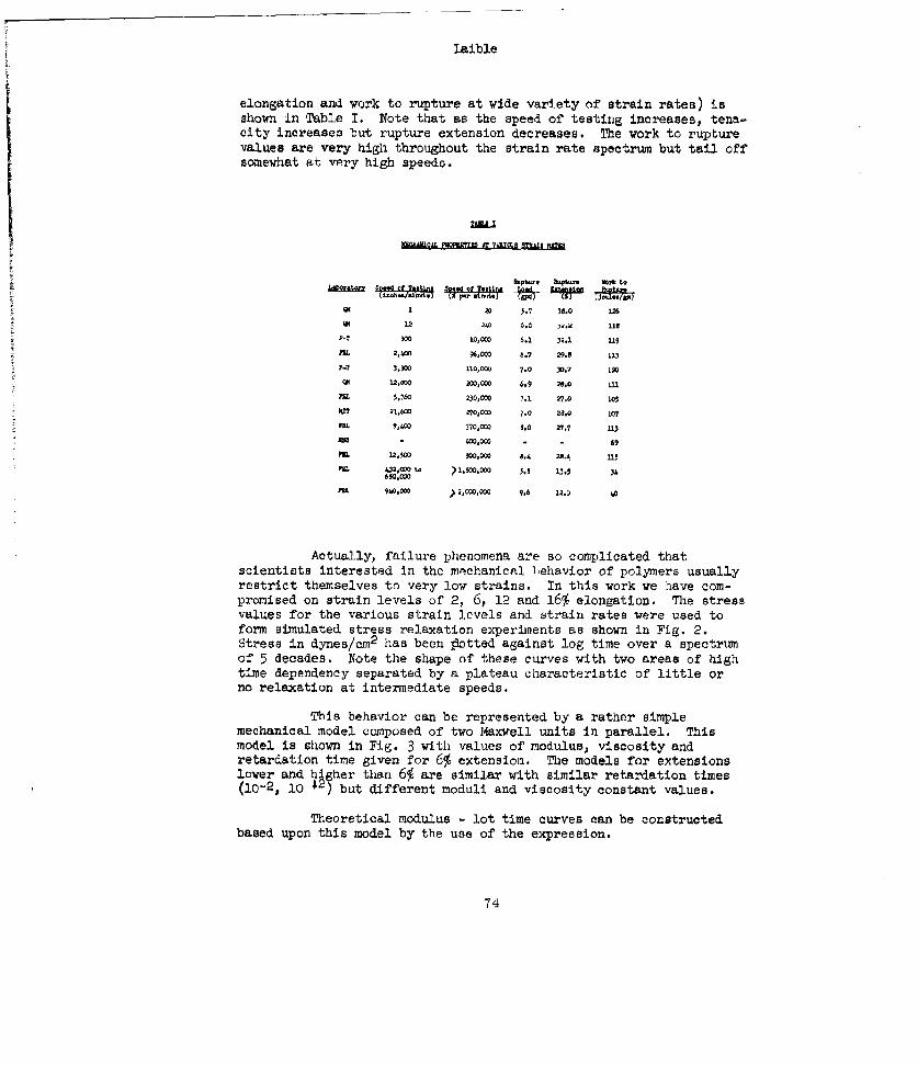
elongation and work to rupture at wide variety of strain rates) isshown in Table 1. Note that as the speed of testing increases, tena-city increases but rupture extension decreases. The work to rupturevalues are very high throughout the strain rate spectrum but tail offsomewhat at very high speeds.
991 20 5.7 38.0 16
1.2 36. 0 us1- 0 0,000 6.1 32.1 119
FRI 2,CO 96,000 6.7 29.8 L13
P-? 3,0W [10,00 7.0 30.7 120
41 12,O• 200,000 6.9 28,0 .1.
F5,760 230,000 7.1 27,0 L0o
)a? 21,600 270,000 7.0 28.0 107
F 9.9,400 nO30, 8.0 27.7 113
IR4OS 4,000 - 69
MR 12,2500 700,000 8.4 24.L U5
FRI 22.01 t4 ý250' 5.5 U1.5 36650,000P&L 90,0D0 > 2,000,0 9.6 120 40
Actually, failure phenomena are so complicated thatscientists interested in the mechanical behavior of polymers usuallyrestrict themselves to very low strains. In this work we have com-promised on strain levels of 2, 6, 12 and 16% elongation. The stressvalues for the various strain levels and strain rates were used toform simulated stress relaxation experiments as shown in Fig. 2.Stress in dynes/cm2 has been p1otted against log time over a spectrumof 5 decades. Note the shape of these curves with two areas of hightime dependency separated by a plateau characteristic of little orno relaxation at intermediate speeds.
This behavior can be represented by a rather simplemechanical model composed of two Maxwell units in parallel. Thismodel is shown in Fig. 3 with values of modulus, viscosity andretardation time given for 6% extension. The models for extensionslower and higher than 6% are similar with similar retardation times(10-2, 10 42) but different moduli and viscosity constant values.
Theoretical modulus - lot time curves can be constructedbased upon this model by the use of the expression.
74
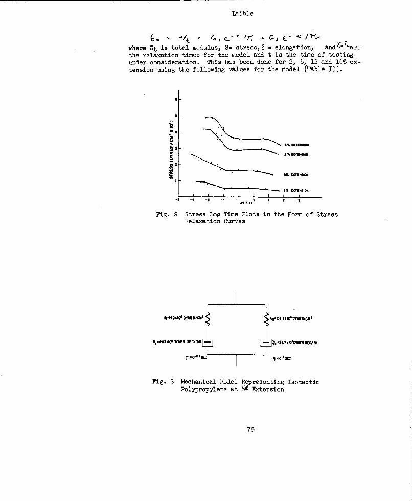
Laible
where Gt is total modulus, S= stress, a * elongRtion, and ',arethe relaxation times for the model and t is the time of testingunder consideration. This has been done for 2, 6, 12 and 16% ex-tension using the following values for the model (Table II).
1% IXTENSION
• $ -4 -•1 -• -I 4* (~u I t a
Fig. 2 Stress Log Time Plots in the Form of Stres5Felaxa~ticn Curves
1,
I-Fig. 2 Stessnia L.og iePlot ersning theormafctres
Polypropylene at 6% Extension
7-5
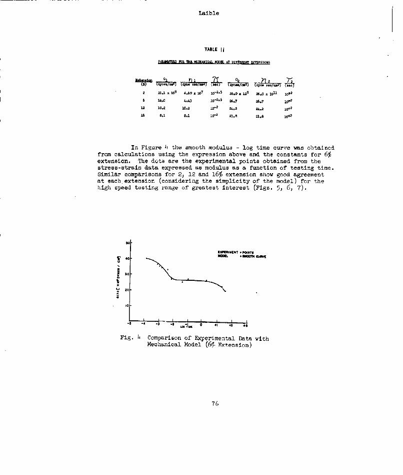
Laible
TABLE I1
PAMMITh PFOR li NEGCRAICM NMoD. AT DIp•,•WM •IoRS
1d•-..aeW (09k(00) (43 0 ,e0y 02 /u,4) 42 21.1 x 10⁹ 6.69 z 10
7 10-2.5 26.0 . 109 g6.0 z IOU 10t2
6 14.0 4.43 o"2.ý 26.7 26.7 10*
12 10.2 10.2 10-2 24.2 24.2 10t
16 8.1 8.1 10"a 21.8 21.8 10
In Figure 4 the smooth modulus - log time curve was obtainedfrom calculations using the expression above and the constants for 6%extension. The dots are the experimental points obtained from thestress-strain data expressed as modulus as a function of testing time.Similar comparisons for 2, 12 and 16% extension show good agreementat each extension (considering the simplicity of the model) for thehigh speed testing range of greatest interest (Figs. 5, 6, 7).
0.
EKlq[tlilMlhT * POllNT,
20
-o
Fig. 4 Comparison of Experimental Data withMechanical Model (65. Extension)
76
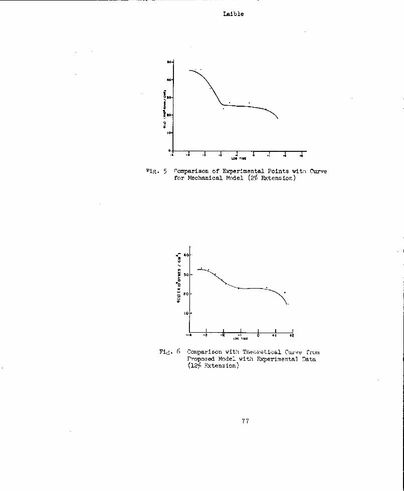
Laible
40-
I I
-5, -4 -3 -a -4*LOS TIME
'ig. 5 Pomparison of Experimental Points vita Curvefor Mechanical Model (2% Extension)
-40-
M
•z 30
zo-
10
I I I I-4 -3 -2 -I 0 + 1 +2
Lo TIME
Fig. 6 Comparison with Theoretical Curve fromProposed Model with Experimental Data(12% Extension)
77
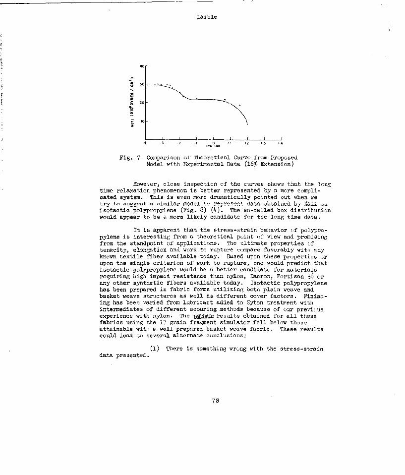
Laible
40
U*030
w20
N
10
-4 - - - -! -• I 4LOG T.ll
Fig. 7 Comparison of Theoretical Curve from ProposedModel with Experimental Data (16% Extension)
However, close inspection of the curves shows that the longtime relaxation phenomenon is better represented by a more compli-cated system. This is even more dramatically pointed out when wetry to snaff~st. a si1mi1n mnvie.1 I- -pr data obtanincd by L1all un
isotactic polypropylene (Fig. 8) (4). The so-called box distributionwould appear tc be a more likely candidate for the long time data.
It is apparent that the stress-strain behavior of polypro-pylene is interesting from a theoretical poinJi of view and promisingfrom the standpoint or applications. The ultimate properties oftenacity, elongation and work to rupture compare favorably with anyknown textile fiber available today. Based upon these pruperties orupon the single criterion of work to rupture, one would predict that
isotactic polypropylene would be a better candidate for materialsrequiring high impact resistance than nylon, Dacron, Fortisan 36 orany other synthetic fibers available today. Isotactic polypropylenehas been prepared in fabric forms utilizing both plain weave andbasket weave structures as well as different cover factors. Finish-ing has been varied from lubricant added to Syton treatment with
intermediates of different scouring methods because of our previcusexperience with nylon. The bgoistic results obtained for all thesefabrics using the 17 grain fragment simulator fell below thoseattainable with a well prepared basket weave fabric. These results
could lead to several alternate conclusions:
(i) There is something wrong with the stress-straindata presented.
78
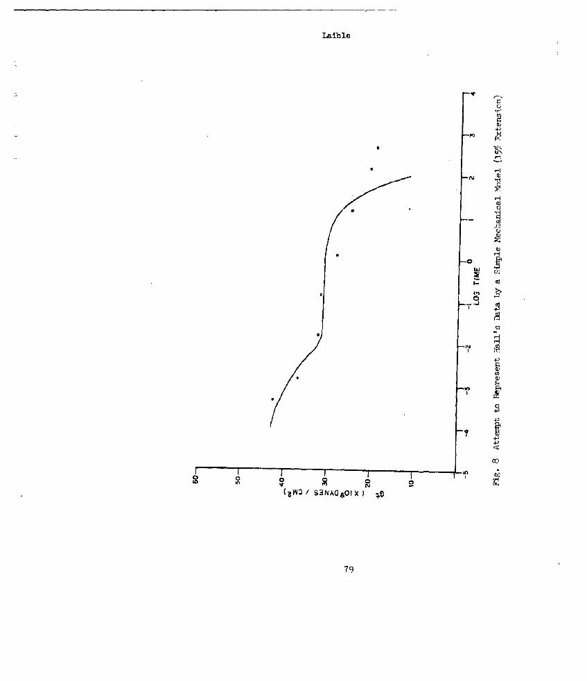
Laible
'4)
'-4
H
14z
to a
rn1
S3NOO X-
79H
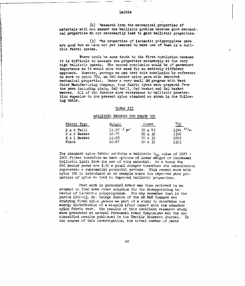
Laible
(2) Research into the mechanical properties ofmaterials will not answer the ballistic problem because good mechani-cal properties do not necessarily lead to good ballistic properties.
(3) '1he properties of isotactic polypropylene yarnare good but we have not yet learned to make use of them in a suit-able fabric system.
There could be some truth to the first conclusion becauseit is difficult to measure the properties accurately at the veryhigh ballistic speeds. The second conclusion would be of paramountimportance as it would show the need for an entirely differentapproach. However, perhaps we can test this conclusion by referenceto work on nylon 700, an 540 denier nylon yarn with improvedmechanical properties. Under a very small QM program with WestPoint Manufactiring Company, four fabric types were prepared fromthe yarn including plain, 2x2 twill, 2x2 basket and 2xl basketweaves. All of the fabrics show resistance to ballistic penetra-tion superior to the present nylon standard as shown in the follow-ing table.
TABLE III
BALLISTIC RESULTS FOR NYLON 700
_____c _________._. Count
2 x 2 Twill 11.97 , 50 x 43 1344 ,2 x 2 Basket 12.77 56 x 30 13062 x I Basket 11.08 56 x 30 n-65Plain 10.67 50 x 31 1323
The standard nylon fabric exhibits a ballistic V50 value of 1225 -1260 ft/sec therefore we have options of lower weight or increasedballistic limit from the use of this material. As a bonus the840 denier yarns are $.50 a pound cheaper therefore the substitutionrepresenta a substantial potential savings. This recent work withnylon 700 is introduced as an example wnere thne improved yarn pro-perties of nylon do lead to improved ballistic properties.
Past work in personnel armor was then reviewed in anattempt to find some other solution for the disappointing be-havior of isotactic polypropylene. You may remember that in theperiod 1950-53, Dr. George Susich of the QM R&E Command wasstudying fired nylon panels as part of a study to determine tneenergy distribution of a missile after impact with the standardnylon fabric vest. The results of this excellent research studywere presented at several Personnel Armor Symposiums and the un-classified results published in the Textile Research Journal. Inthe course of this investigation, tae actual number of yarns
80
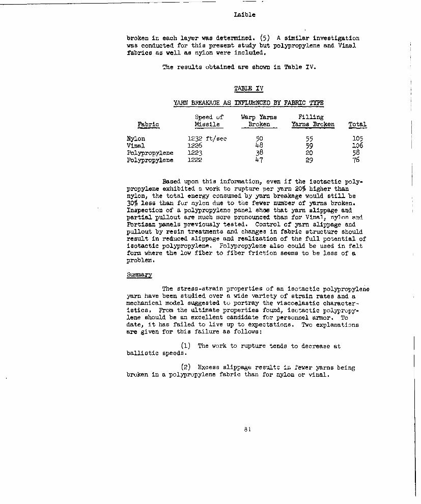
Laible
broken in each layer was determined. (5) A similar investigationwas conducted for this present study but polypropylene and Vinalfabrics as well as nylon were included.
The results obtained are shown in Table IV.
TABLE IV
YARN BREAKAGE AS INFLUENCED BY FABRIC TYPE
Speed of Warp Yarns FillingFabric Missile Broken Yarns Broken Total
Nylon 1232 ft/sec 50 55 105Vinal 1226 48 59 106Polypropylene 1223 38 20 58Polypropylene 1222 47 29 76
Based upon this information, even if the isotactic poly-propylene exhibited a work to rupture per yarn 20% higher thannylon, the total energy conswned by yarn breakage would still be30% less than for nylon due to the fewer number of yarns broken.Inspection of a polypropylene panel shoe that yarn slippage andpartial pullout are much more pronounced than for Vinal; nyfln antFortisan panels previously tested. Control of yarn slippage andpullout by resin treatments and changes in fabric structure shouldresult in reduced slippage and realization of the full potential ofisotactic polypropylene. Polypropylene also could be used in feltform where the low fiber to fiber friction seems to be less of aproblem.
Sumary
The stress-strain properties of an isotactic polypropyleneyarn have been studied over a wide variety of strain rates and amechanical model suggested to portray the viscoelastic character-istics. From the ultimate properties found, isotactic polypropy-lene should be an excellent candidate for personnel armor. Todate, it has failed to live up to expectations. Two explanationsare given for this failure as follows:
(1) The work to rupture tends to decrease atballistic speeds.
(2) Excess slippage results ir. fewer yarns beingbroken in a polypropylene fabric than for nylon or vinal.
81
laible
The most important conclusion from this work is that wemust gain an understanding of the penetration of materials whetherthese materials be metal, fibers, plastic sheets or felts. Theadvantage to be gained from the use of higher tenacity yarns isevident from the excellent ballistic resistance exhibited byfabrics prepared from nylon 700. However, although we want hightenacity yarns, there is no point in spending too much mcney tr)produce a 9 gpd or 12 gpd polypropylene yarn until we have solvedthe basic problem of the mechanism of penetration of the 6-7 gpdpolypropylene. This is the approach we have been following and bythe next symposium we hope to have modified the polypropylenefabric so that its full potential is realized.
82
Lalble
References
1. Laible, R. C. "New High Tenacity Fibers for Personnel Armor"Department of Defense Armor Symposium, Natick, Mass., 7-9June 1960, pp. 131 - 6 (5).
2. Laible, R. C. and Morgan, H. M. "The Viscoelastic Behavior ofOriented Polyvinyl Alcohol Fibers at Large Strains" J ofPolymer Science 5•4 159, 53-63s 1961
3. Morgan, H. M. and Laible, R. C. "A Mechanical Model toRepresent the Vincoelastic Properties of Polypropylene"Textile Research J. , November 1961, (in print).
4. Hall, 1. H. "Time Dependent Tensile Strength of Solids"Nature 189, 131 (19617
5. Susich, 0. Unpublished work 1958.
83
BUOYANT INSULATING BODY ARMORS FROM STAPLE FIBFlRS
M. C. JaskowskiMellon InstitutePittsburgh 13, Pa.
Abstract
Staple fibers show great promise as effective personnel bodyarmor. In contrast to the multifilaments used in the nylon armorcloth, these armors contain cut fibers of relatively Low tenacity,1.5-3 grams per denier. In order to convert the staple fibers intousable forms, trey are carded into a batt, essentially a laminatedweb structure, which is then compressed to desirable thicknesses.
"Thel bul]listir te.t emp.oyel] Js a modification of the proposedmilitary standard acceptance method which utilized the .22 T-37 (17grain) fragment similator. Initially, the 0.020 inch thick aluminumwitness plate served as a means of determining the limiting veloci-ties of the test samples; but this was replaced by a device capableof accurately measuring the velocities of the projectiles whichpass through the armor samples. With this technique, the protectiveefficiency of an armor can be found at any striking velocity above thelimiting velocity. By plotting initial or striking velocity vs. per-centage loss of velocity due to the sample (i.e. percentage oforiginal energy of the projectile absorbed by the sample), a curve maybe drawn from which one may readily obtain the value representing thevelocity at which complete arrestment of the projectile is attained.
The ballistic performances of carded fibrous batts havebeen found to be dependent upon fiber type, fiber length, fiberdiameter, surface characteristics of tne fiber and the areal densitiesof the mats. By the addition of an efficient water-repellent, a battcomposed of fine fibers may be transformed into a thermal insulatingbody armor possessing an outstanding degree of buoyancy.
84
Jaskow'sk I
Introduction
In 195h the Bureau of Ships became interested in JineorporJit-ing ballistic protection into the bulk-type life preservers. Thestandard buoyant filler, fiber glass, offered little if any, protec-tion against shrapnel. The problem was to replace the g wac J ,ith P
material capable of' maintaining the same level of buoyancy hut. wit]; ahigh degree of resistance to shrapnel penetration. Organic staplefibers presented the greatest possibilities. The author Jnvectigal-(tdthe application of various staples to life preservers while the actualballistic tests were conducted at the Naval flesearch Laboratories andthe DIhlgren Naval Proving Grounds.
Subsequent to this work, the Bureau of Supplies and Ac-counts through the U S. Naval Supply Research and DevelopmentFacility became cognizant of' the possibility of' preparing an uniquejacket liner with excellent thermal insulation, sufficient buoyantproperties to keep the weaver afloat for a reasonable period and anadequate measure of ballistic protection. The performance of thisliner would be limited, however, by those conditions accompanyingpractical applications such as drape, weight, size, etc. The initialrequirements suggested a liner 3/8" - 1/2" thick and with an arealdensity of 10 - 20 oz/yd2 .
In contrast to the armors using high tenacity filaeritssuch as nylon or fiber glass, (8 - 10 grams/denier), we will discussthose that are composed of staple fibers of low tenacity (1.5 -3.0 gris/denier) . At this time, a comparison between the mechanispsapparently employed by the two systems to withstand projectilepenetration would be pertinent. In the case of the Doron or nylonarmor cloths, the energy of the striking projectile is expendedmainly in two ways: one, by breaking or shearing the filaments and,two, by de-laminating the layers. In the staple-fiber batts, re-tardation of the projectile is due essentially to the dissipation ofenergy through the movement of fibers against fibers as they arepushed aside by the projectile. When the spinning pellet first en-gages the fibrous sample, it is immediately wrapped with fibers.This increases its size, resulting in greater hindrance to its pass-age.
During the presentation of the data accumulated, it sYiou1rbe remembered that the scope of the ballistic investigation wasdictated by the buoyant and insulation requirements of the program;such as fiber diameter and the use of a water-repellent.
85

Jaskowski
Preparation of Test Samples
For the preparation of the test liners, the staple fiberswere carded to form batts. These are essentially lamirat!:ý struc-tures, representing multi-layers of fibrous webs. The batts, unlessotherwise indicated, were placed between cotton print cloth covers U.adthen between two rigid metal sheets which could be separated at anypredetermined distance. 'The thickness of the sample was thus keptconstant over its entire area. Holes in the metal, relatively largein comparison with the diameter of the projectile, permitted pasga&eof the projectile.
Testing Procedure
The ballistic tc;t metihod employed wus bimilar to the pro-posed military standan'd •o•rptance method utilizing the .p2 calibcrT-57 (17 grain) fragment simulator. Originally, the prescribedaluminum witness plate served to indicate the ballistic effectivenessof the samples. Eventually, this was replaced with two accuratelyspaced detectors capable of' determining the velocities of those pro-jectiles which pass through the samples. Thus the initial andresidual velocities can easily be obtarined as well as the amount of'energy absorbec by the test specimens.
Nomenclature
Our riefinition of the term "limiting velocity" which will l,eused repeatedly is that range of' velocities between partial penetra-tion and no penetration. Of course this applies only in those caseswhere the aluminum witness plate was used. On the other hand, whenthe initial and residual velocities were found, snd a curve obtainedby plotting initial velocity versus the percentage velceity loss 2ueto the sample, the limiting velocity is that point resultin( from the.extrapolation of the curve to lO, velocity loss.
Experimental Results
Generally at velocities slightly below the limitlnýr ve-locities of these carded staple batts, conical fiber wads are founh
86
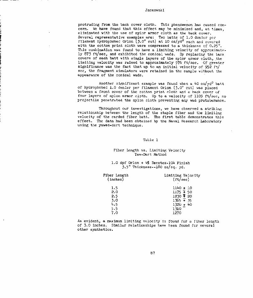
Jasaowski
protruding from the back cover cloth. This phenomenon has caused con-cern. We have found that this effect may be minimized and, at times,eliminated with the use of nylor armor cloth as the back cover.Several representative examples are: Two batts of 1.0 denier perfilament hydrophobed Orlon (5.0" cut) at 10 oz/yd2 each and coveredwith the cotton. print cloth were compressed to a thickness of 0.25".This combination was found to have a limiting velocity of approximate-ly 873 ft/see, and exhibited the conical wads. By replacing the backcovers of each batt with single layers of the nylor armor cloth, thelimiting velocity was raised to approximately 976 ft/sec. Of greatersignificance was the fact that up to an initial velocity of' 952 ft/sec, the fragment simulators were retained in the sample without theappearance of the conical wads.
Another significant example was found when a 40 oz/yd2 battof hydrophobed 1.0 denier per filament Orlon (3.0" cut) was placedbetween a front cover of the cotton print cloth and a back cover offour layers of nylon armor cloth. Up to a velocity of 1109 ft/see, noprojectile penetrated the nylon cloth preventing any wad protuberance.
Throughout our investigations, we have observed a strikingrelationship between the length of the staple fiber and the limitingvelocity of the carded fiber batt. The first table demonstrates thiseffect. The data had been obtained by the Naval Research Laboratoryusing the yawed-dart technique.
Table 1
Fiber Length vs. Limiting VelocityYaw-Dart Method
1.0 dpf Orlon + 4% Decetex-l04 Finish3.5" Thickness--180 oz/sq. yd.
Fiber Length Limiting Velocity(inches) (ft see)
1.5 114o + 102.0 1175 : 502.5 1230 203.0 1365 + 554.5 1320 + 4o5.5 1)107.0 1270
As evident, a maximum limiting velocity is found for a fiber lengthof 3.0 inches. Similar relationships have been found for severalother synthetics.
87
Jaskowskt
The effect of fiber diameter upon ballistic performance wasobserved. Since buoyancy and thermal insulation of staple fiber battsare indirectly proportional to fiber diameter, it was necessary todetermine whether ballistic protection was simllarly affected, Fortu-nately, we have found this to be true, Figure I exemplifies the re-lationship. The physical characteristics of the Dynel staple fiberswere identical in all respects, e.g., length, crimp, finish, with onlya variation in their diameters. With reference to Figure II, a com-parison between 0.5 denier and 1.0 denier Acrilan fibers again demon-strates superior ballistic performance by the "finer" fiber.
As you will observe throughout the presentation of the ex-perimental data, a majority of the staple batts were prepared at anareal density of 42 oz/ydp. Although our interest lies in fibrousliners with areal densities up to 20 oz/yd2, the heavier samplesserved to differentiate between the various fibers and finishesGenerally, the limiting velocities of the 42 oz batts were in therange 900 ft/sec to 1200 ft/sec.
The relationship between areal density and limiting veloci-ty at a constant thickness was obtained for 1.0 denier per filamentOrlon (5.0" cut) and 1.5 denier per filament Dacron (3.0" cut),These fibers were chosen because of their superior buoyant character-istics. A comparison of the resultant curves (Figure ]I:), showsthat the Orlon batts are slightly superior. The extrapolation of theOrlon curve promises extremely large limiting velocitics at airaidensities greater than 45 oz/yd2 .
Figure IV is the first representation of what we havetermed "protective efficiency" of two fibrous batts. The percentageloss of initial velocity due to the sample batt is plotted againstinitial velocity. Thus at velocities greater than the limitingvelocity, the effectiveness of the liners in slowing down the pro-jectiles can be known. The limiting velocity can also be found byextrapolating the curve to 100% velocity loss.
Of the staples examined to-date, it appears that 1.0 dpfOrlon (3.0" cut) exhibits the highest ballistic performance,Originally, only hydrophobed Orlon fibers were tested, the presence ofa water-repellent being required for buoyancy. However, the effect of'this finish and others upon ballistics became of interest academical-ly. A comparison between the Decetex-104 silicon finish, the originalanti-static agent applied by the manufacturer and hydrophobed aerogelis presented in Figure V. A visual examination of these three sampleshave shown that the Decetex best reduces the fiber-to-fiber frictionwhile the aerogel increases the friction tremendously. The curvesmay, therefore, be interpreted as showing that any Increase in thefiber-to-fiber friotion above that for the Decetex sample, lowers theability of the batts to withstand fragment penetration. We have ob-served this effect with other fibers, that decreasing the mobility ofthe fibers below a certain value decreases the ballistic efficiency.
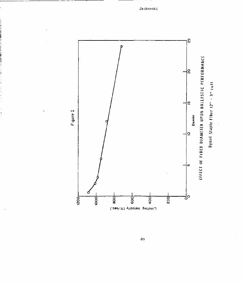
Jaskowski
d<
0
1-4-
.U -
Ls.6
LL..
I-
L)
LA-
0 0 0 0 0 0
89
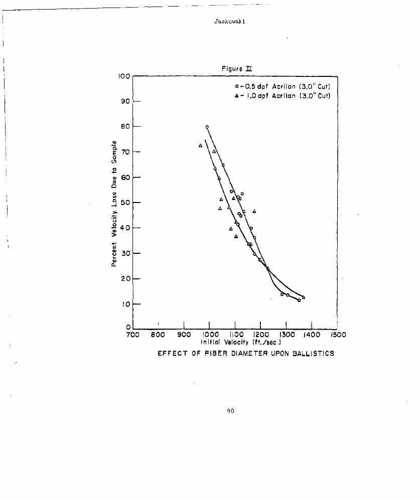
JaskowsIk i
Figure L100
0-0.5 dpf Acrilan (3.0" Cut)
A- .0 dpt Acrilan (3.0" Cut)90
80
C,,)
0S60-
>
30,0
200t50
C,S30--h.
20-
o0 I I I l I I I700 800 900 1000 1100 1200 1300 1400 1500
Initial Velocity (ft./sec,)
EFFECT OF FIBER DIAMETER UPON BALLISTICS
90
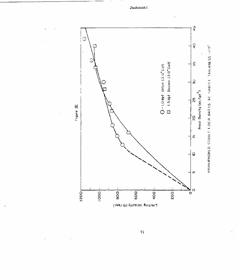
Jaskowsk i
K<
IN0
L)n
0 0 0c 0-0 0
co CDIt C
COO/4 4101A BIO IK
91N
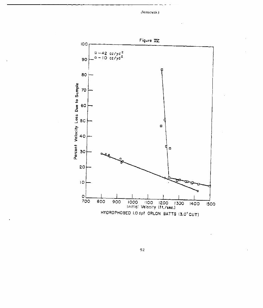
Jaskowsk j
Figure 1Z100
U-42 oz/yd 2
90 0- 10 oz/yd2
80
w
E 70
•,60--
50
.. J
0340-n 60
20--
10-
700 830 0 900 1000 1100 1200 13500 1400 1 S00Initial Velocity (ft,/sec.)
HYCROPHOSED I.Odpf ORLON BATTS (3.0" CUT)
90
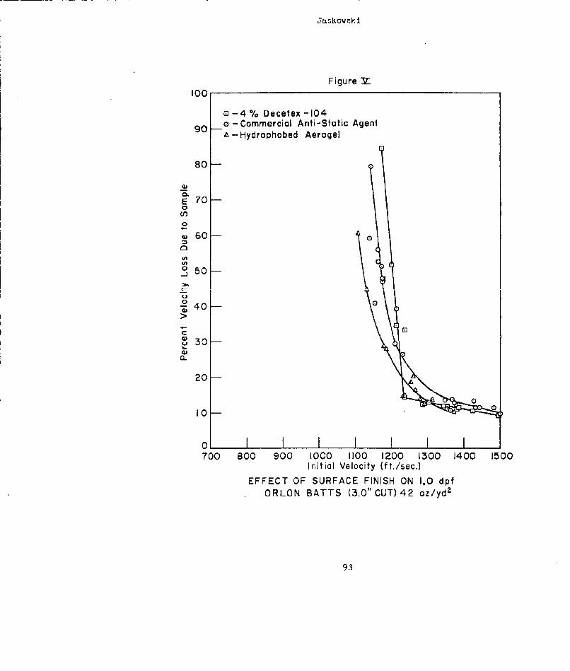
Jr~skowsk i
Figure M100
o -_4 % Decetex -104e-Commercial Anti-Static Agent90 -Hydrophobed Aerogel
E 70-0C3
0
60
U0 50
40- 4
S30-
20-
l00I0-
700 800 900 1000 1100 1200 1300 1400 1500Initial Velocity (ft./sec.)
EFFECT OF SURFACE FINISH ON 1.0 dpfORLON BATTS (3.0" CUT) 42 oz/yd2
93
Jaskowsk i
There are three coimmercially-available staple fibers withsmall diameters which form highly-buoyant batts. These are 1.0 dpfOrlon (3.0" cut) 1.0 dpf Acrilan (3.0" cut) and 1.5 dpf Dacron Type5400 (35.o" cut). A comparison between the ballistic efficiencies of'these was made and can be seen in Figure VI.
For numerous reasons, manufacturers occasionally altetr,chemically or physically, their commercial staple fibers. This, weknow, can affect the ballistics of carded batts prepared from them.As an example, we have found that hydrophobed batts of 1.5 dpf DacronType 54OO (5.0" cut) are considerably superior ballistically to thosecontaining hydrophobed 1.5 dpf Dacron Type 64 (2.5" cut). The differ-ence in the staple length does not appear to account for the greatdifference in the ballistic efficiencies. Figure VII contains therepresentative curves.
The present phase of our investig~tion encompasses thepreparation and testing of fiber blends and composites. Preliminarywork has been done using mixtures of 1.5 dpf Dacron and 0.5 dpfAcrilan. By referring to Figure VIII, one may perceive that the50/50 blend and composite are essentially equal ballistically and havethe effect of totally up-grading the Dacron as well as increasing thelimiting velocity of the 0.5 dpf Acrilan.
The last two figures show the "protective efficiencies" of'the Doron armor and the 12 layer nylon armor cloth. In F!E•_re aconziderabie variation exists among the points obtained. It appearslogical to assume that these are due to inconsistent delamination,which, in turn, may be attributed to irregularities encountered inmanufacture. The same inconsistencies exist in the results of theballistic tests upon the nylon armor. Here again, the delaminationof the spot-sealed layers appears to have a great effect.
An interesting and significant interpretation of the "pro-tective-efficiency" data for the 1.0 lpf Orlon butt at an arealdensity of 42 oz/yd 2 and either the Doron or nylon armor, points tothe preparation of a composite armor capable of' protecting the wearerfrom 17 grain projectiles traveling at velocities up to 1(-00 ft/sEc.Only if these materials were positioned properly could this protectionbe achieved. If the Orlon butt were used as the outo;idc layer wr.icr.would be struck first by the projectile travelln(: 1600 ft/sec, itwould be easily penetrated with the residual velocity of the proWjec-tile being greater than 1350 ft/sec. This residual value fart ex-ceeds the limiting velocity of the Doron, resulting in conjpete pcn(!-tration of the composite. However, if the Doron were placeJ outsideto encounter the projectile first, the initial velocity would helowered by 36 - 37% during its passage through the Doron. Theresidual. velocity would be slightly in excess of 1000 ft/sec. Th½value is less than the limiting value of the Orlon bhtt. The pro-jectile would be completely contained.
94
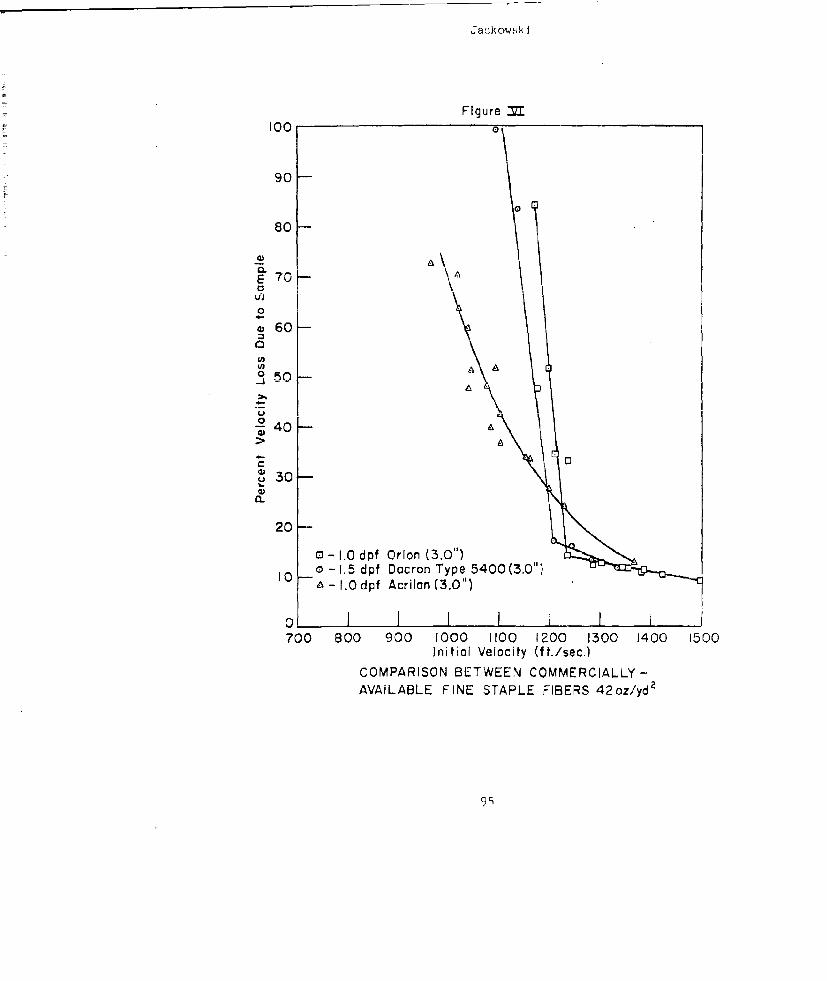
Ja ,;k ow ik i
Figure900 o
90
80-
w 70
4 60-
0 5
40-
QL
20-
-4l.0dpf Orlon (3.0")
10 - o -1. 5dpf Dacron Type 5400 (3.0")A-- 1.Odpf Acrilan(3.0")
700 800 900 1000 1100 1200 1300 1400 1500Initial Velocity (nt./se..)
COMPARISON BETWEEN COMMERCIALLY -
AVAILABLE FINE STAPLE FIBERS 42oz/yd2
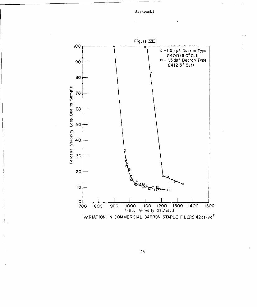
Jaskowsk i
Figure MZ
_00 -- o-1.5dpf Dacron Type
5400 (3.0" Cut)90 a - 1.5dpf Dacron Type
64 (2.5" Cut)
80--
, 60
0 50--U,U,
0
Cl 30-
20
10-
0700 800 900 1000 1100 1200 1300 1400 1500
Initial Velocity (ft./sec.)
VARIATION IN COMMERCIAL DACRON STAPLE FIBERS 42oz/yd2
96
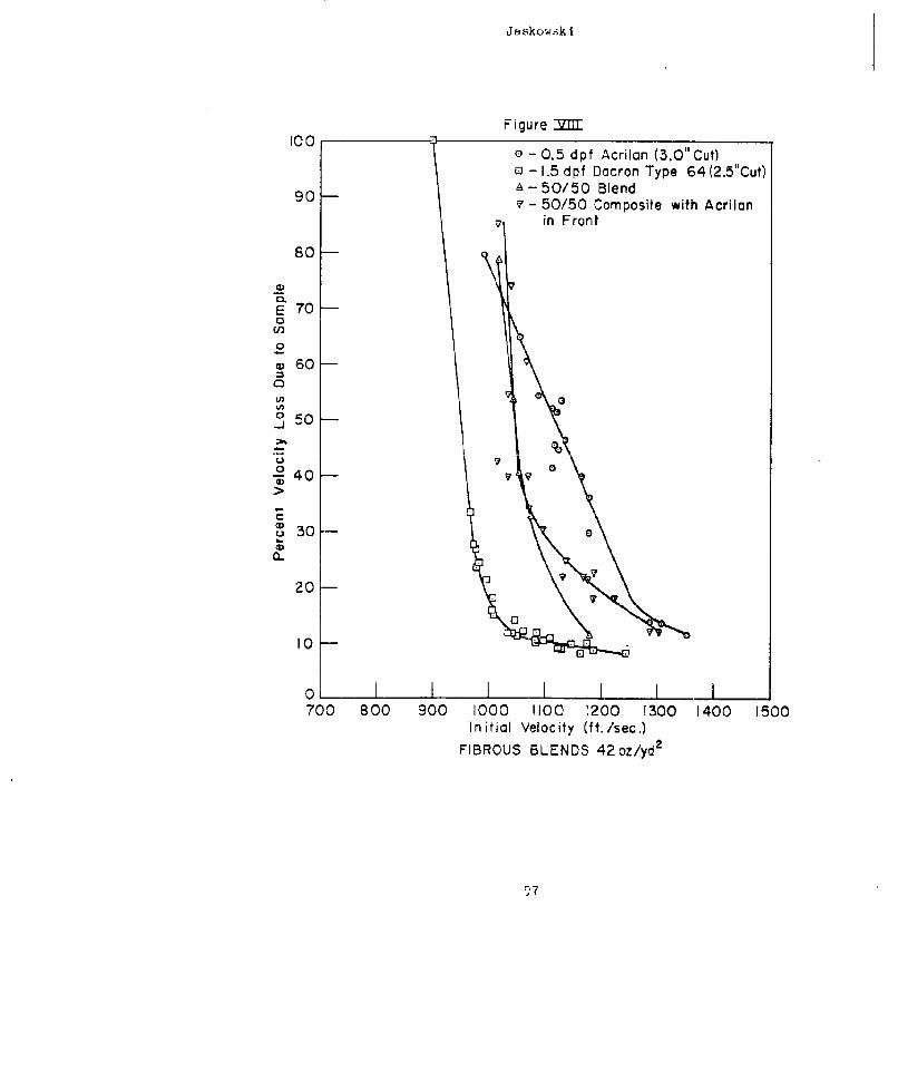
Jaskow,3k i.
Figure -I1"F100
O-0.5 dpf Acrilan (3.0" Cut)o - 1.5 dpf Dacron Type 64 (2.5"Cut)
90 A-50/50 Blend
S- 50/50 Composite with Acrilanin Front
80
C)
E 70-
10
0 60
250
U 010--40-
730--- 0a)
20 --
I0-
0 I I I I I II700 800 900 1000 !100 1200 1300 1400 1500
Initial Velocity (ft./sec.)FIBROUS BLENDS 42oz/yd2
97
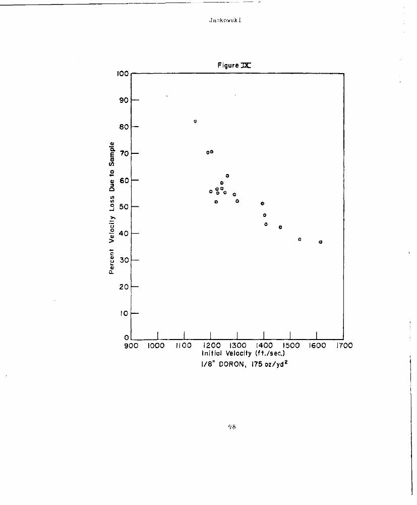
Ja.;k owsk i
Figure MI00
90-
80-
rE 70- e
04- 000S60-So%
0 50
00Z- 40-->
C
S30-
20-
I0-
0 - I I I I I I900 I000 1100 1200 1300 1400 1500 1600 1700
Initial Velocity (ft./sec.)
1/8" DORON, 175oz/ydz
98
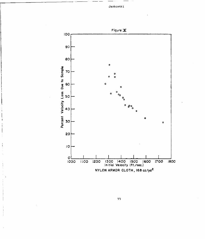
Jaskowski
Figure X100
90-
80-
IV 700E 70 --
En 0U)o0
g60- 0
0)W 0 00j 0
S0
0 0
20-
20-
10-
01000 1100 1200 1300 1400 1500 1600 1700 1800
Initial Velocity (ft./sec.)
NYLON ARMOR CLOTH, 168 oz/yd2
99
Jaskowsx i
In closing, I wish to emphasize the over-all contributions ofbuoyancy and thermal insulation to personnel body armor. Our testshave shown that batts composed of these hydrophobed "fine" fibers arevastly superior to many thermal insulating liners presently In use,such as both solid and perforated Polyvinylchloride foams.
100
SOME U. S. ARMY RESEARCH OFFICE SPONSORED RESEARCH
Dr. Sherwood Githens, Jr.Deouty Chief Scientist
U. r. rm•y Research Office33x (31, bake Station, Durham, N. C.
6elected b:,sic pre;Jar'h orojects sponsored by the U. S.Army Research 0ff ,I, having possible applications to the developmentof body armor wce discussed by Dr. Githens.
Identification of these projects by proposal number andtitle with a brief of the scope of the projects is given below. Acompilation of the projects including bibliographies may be obtainedupon request to Dr. Githens at b]i-Ž, address given above.
1235-E STUDY OF THlE MECHANISStS OF TiHE INIITIATION OF PLASTIC FLOWAND FRACTURE IN METALS
coýe: Investigations will be made of the initiation of: (1) brittlefracture in steel in bhe presence of notches; (2) fracture in singlecrystals of zinc; and (3) yieidin, i.n zinc single crystals associatedwith the initiation of' fracture.
1253-E RESEARCH AND DEVELOPMENT AND THEORETICAL ANALYSI'S OF SCABBINGIN MATER IALS
Scope: (i) Studies will be continued on scabbing damage in materialsand on stress wave propagation and dynamic properties of materialsaffecting scabbing; (2) theoretical analysis of stress waves inhardened steel plates, effect of backing materials, elasto-plasticand shook-type disturbances, and delay-time effects will also bestudies; and (3) an experimental program will be set up to studybrittle fracture in metals using plaster-of-Paris models.
101
Githens
1283-E A STUDY OF PHOTOELASTICITY, PHOTOPLASTICITY, AND PHOTOELASTICMATERIALS
Scope; The study is being continued on (a) three-dimensional photo.,elasticity of non-spherical objects; (b) dynamic photoelasticity;(c) improvement of photoelastic materials; and (d) photoplasticity.
1325-E PROPAGATION OF ELASTIC AND PLASTIC STRAIN PULSES IN BOUNDEDSOLIDS
Scope: (1) An attempt will be made to analyze theoretically theeffect of the latcral Inertia of a bar on the dispersion of a plasticstrain pulse in a cylindrical bar; (2) experimental studies will beextended on the propagation of plastic strain in a lead bar, particu-larly with the use of single crystal or extruded specimens; and(3) preliminary studies will be made with geometrical shapes otherthan that of a un-ifurmni cylinda-ical bar to determine the feasibilityof obtaining extremely high stresses in solids by implosion.
1740-E ULTRASONIC MODEL STUDY OF ELASTIC WAVES IN LAYERED 1EDIA
Scope: By the utilization of ultrasonic elastic waves, a study willbe made of the physical properties of layered media. Specific ob-jectives will include: (1) the flexual wave propagation in platesof varying thickness; and (2) the study of the radiation pattern ofcouprevsiunal and shear waves originating in certain types of rupturessuch as fault slips. Attempts will be made to separate effects at thesource from those of propagation.
1892-E STRESS ANALYSIS IN VISCOELASTIC MATERIALS
Scope: Studies will be made of: (1) use of generalized operators inviscoelastic stress annAysis; (2) development of methods of stressanalysis; (j) investigation of the more general mixed types ofboundary value problems; and (4) effect of unload boundaries whichoffer particular difficulties in applying the method of' functionalequations.
1929-E RELAXATION SPECTRA OF HIGH POLYMERS AND THEIR EFFECT ONVISCOELASTIC RESPONSE
Scope: Research will be concerned with (1) providing spectra ofrelaxation times for certain typical cross-linked and linearpolymers; (2) studying the effect of polymer structure and filler ondynamic behavior as well as on stress relaxation; (3) studying theeffect of temperature with respect ýo mechanical behavior, particu-larly with respect to the inhomogeneity produced by temperaturegradients; and (4) establishing rational methods of viscoelasticanalysis for types of polymers based on the experimental results.
102
Githens
2573-E RESEARCH IN FINITE AMPLITUDE WAVE PROPAGATION aN SOLIDS
Scope: Studies will be made of (1) the compression behavior ofalupmnum to the point where the stress-strain curve begins to turnupward; (2) strain rate effects in lead and copper, particularlywith reference to the Malverne theory of strain rate wave propagation;and (3) dimetral effects in aluaainun' for the first one and one-halfdiameters from the impact face. The method of measurinm. Poisson'sratio and dilatation will be applied in all cases.
2589-C DYNAMIC MECHANICAL PROPERTIES OF POLYMERS AND THIEIR SOLUTIONSAND GELS
Scope: A study will be made of certain polymers and polymer-plasti-cizer systems by a double transducer apparatus and other experimcntalmethods to measure, in each case, the in-phase and out-of-phasecomponents of the dynamic shear modulus and other time-depenrdentproperties over a wide range of temperatures and frequencies. Thedata will be analyzed to provide certain basic time-dependent andtemperature-dependent functions.
2998-E STUDIES OF PLfSTIC 'WAVE PROPAGATION
Scope: The research is to consist of both theoretical and experi-mental studies of flcxura.l waves and of longitudinal waves. In thetheoretitpf .tiiAis, the effects of latcral inertia a-- d shear willbe incorporated in the equations and the experimental work will bein direct support of the theoretical work. The studies of lonyitu-dinal waves will be an extension of the work reported at Lite SecondPlasticity Symposium at Brown University and sponsored f.revi:)usly bythe University of Texas Research Tnotitute.
3055-E EFFECT OF RATE OF !*O' .nb . 1AT'h TOPTr~n'w .N THIH DEFORmATfONALBEHAVIOR OF ROCKS
Scope: The dynamics of rock deformation can best be studied thrmui;tcontrolled laboratory experiments in which the important naturalenvironmental conditions are simulated as realistically as possible.Such experiments not only provide the basis for va-lid interpretatLonof deformational features in rock, i.e., geologic structure, and ameans of determining the conditions which obtained during thedevelopment of that structure, but they also make possible the ore-diction of rock behavior under a variety of physical conditions, afactor of vital importance to many engineering problems. In mostengineering studies of rock prorerties, the rocks are tested only atatmospheric pressure. As the behavior of rock under even low con-fining pressure is often quite different from that under atmosphericpressure, experimental data obtained at atmospheric pressure may bemisleading, if not meaningless, when anplied to situations whereconfining pressure must be considered. All rocks beneath the earth's
103
Githens
surface are, in effect, subjected to confining pressure, owing to theweight of the overburden and to the restriction of the surroundingmedium. Therefore, whenever subterranean construction is to beundertaken, the effect of confining pressure on rock behavior must beconsidered. The anticipated increase in subterranean constructionowing to both improved engineering techniques and necessity_..elgi,aquaducts and other tunnels, intelligence centers and nuclear bombblast caverns or shelters) will require knowledge of the behavior ofrocks under confining pressure and a variety of loading conditions inorder to construct the safest engineering structure with least diffi-culty and least expense. The ability to predict the behavior of rockunder certain imposed conditions will not only be of value duringconstruction, but will also enable the engineer to design thestructure to withstand imposed loads of tectonic or man-made (e.g.,nuclear bomb, rocket thrust) origin. Of particular importance tothe military is the deformational behavior of foundation rock atrocket launching sites. Non-elastic deformation of the foundationrock at the moment uf departure from the launching pad could affectmissile trajectory. Geologists have long been aware of the factthat rocks, ordinarily brittle when deformed in the engineeringlaboratory, commonly undergo flowage when deformed in the earth'scrust. The research here outlined will provide geologists andgeophysicists with a better understanding of the processes andmechanisms of deformation in rocks and the factors which controlindividual processes, as well as provide geologists with a basis forthe valid interoretation of gnonogic structure.
313h-E AN EXPERIMENTAL INVESTIGATION OF DYNAMIC MATERIAL PROPERTIES
Scope: The objective is to determine experimentally the dynamicresponse of several selected types of material to large amplitudepulse type loading. The exporimental techniques have been developedpr,-viously by the invesoigator. A secondary objective of the programwill be the dpt-rminatiorn of the effect of dynamic plastic preloadsof known amplitude on -ule subsequent static behavior of strain-hardening metals.
3176-E DEVELOPMENT OF A MODEL MATERIAL OF LOW PO[SSON'S RATIO FORTHREE-DIMENSIONAL EXPERIMENTAL STRESS ANALYSIS
Scoýpe: It is believed that the material exhibiting a low Poisson'sratio could be a material completely different from the onescommonly used at present, or could be one of the materials used atpresent with transformed properties. In the first case the coopera-tion of people faniliar with the chemistry of resins should be ob-tained. For the second approach some experience has already beengathered by the investigator by enclosing air bubbles or micro-balloons in the liquid resin before casting it. The results obtainedhave not been conclusive, but show that tho approach is feasible.
104
Githens
it is proposed to approach the soluLion of the oroblern full'.,-
Ing the two ways mentioned above and to determine the mechanicalproperties of various ulastics ° One of the plastics exhibiting thedesired properties will be singled out, and used to solve a nra-
selected three-dimensional elastic problem, either photoelastical].yor by means of grids.
3263-E MECHANTCS OF CREEP AND IMPACT FOR PLASTICS
Scope: This research includes experimental and theoretical studieson the mechanical behavior of selected plastics; covering the creepand impact stress-strain-time behavior for simple and combinedstresses. The scope of the studies includes:
1. creep studies
2. high strain rate (impact) studies
"equation .f state" studies
3267-E STRESS-STRAIN CHARACTERISTICS OF MATERIALS AT HIGH RATES OF3TRAIN
Scooe: Three materials will be included in the study: copper,aluminum, and iron. Each of these materials will be at least 99.95percent pure. These particular materials have been selected becausen frrpnt. neal if' informasi on is eivail able- o unee(rn I n them. tlhey arerelatively simple in molecular structure, and a fairly wide variationin strain-rate sensitivity is expected between them. Strains will bemeasured as a function of tIme and distance from the impact end of asemi-infinite bar (12 in. lon,g) of each material at impact velocitiesof 100 and 400 fps. Stresses and strains will be measured usingspecimens 1/2-in, and I in. long using the pressure bar technique tomeasure the stresses and resistance strain -ages for the strain. Thebest of all the techniques which have been developed by the investl-gator during the past ten years for making these measurements will beemployed. Specimens of small diameter will be used to reduce theeffects of lateral inertia. Stresses and strains corresponding t,)
the conditions of the experimental measurements will be computed,
105
DEVELOPMENT OF QMC COMPOSITE ARMOR VEST
E. R. BarronQuartermaster Research & Engineering Command, U. S. Army
Natick, Massachusetts
Man has been on earth but a minute fraction of time in rela-tion to the age of the earth. During this time he has created defen-ses for his protection that are as unusual as any devised by nature,and are in many instances often remarkably similar. Undoubtedly theanimal armor developed in nature must have inspired him to createhis own body armor.
Progress in his armor from the rough shield of tanned skinssLeLurLhed on a wooden frame, came when he found out how to use metal.For many centuries before Christ, the principle of body armor wasemployed by warriors to strengthen armies and lead them to victory.
Such body armor was adapted to combat conditions and tacticsof the times and was of course limited to the available natural mate-rials of sufficient hardness to deflect a blow, the velocity, and in-tensity of which were limited to human force. He also discoveredthat the toughness and strength of metals created other problemssince a sheet of iron or bronze was rigid.
Rigidity in an armored garment was obvious to the armorer,limiting body movement, causing discomfort, and-affecting the combatefficiency of thb warrior. The same problems face the designer ofpresent day body armor. The designers imagination is stimulated bythe work and experience of the Medieval armorer, who was in essence atechnical expert.
One usually envisions armor as the ornate armor of theKnights and the wealthy, used mainly for jousting tournaments andparade, made to order by an army of skilled workers. However con-trary to this consensus was the largc quantities of armor also de-veloped and used by the common foot soldier, made on a mass produc-tion basis.
106
Barron
The Battle of Wisby, which was fought between the Danes andGottlanders in 1361 demonstrates quii:e vividly the armorers technicalskills and efforts to obtain maximum mobility, A mass grave of 1800soldiers (see Figure 1) was uncovered accidentally in 1905, whichpresented the pathetic picture of the horrors that accompanied a warof those days. The army was made up of peasants who patched up anddonned old suits of armor for the hand to hand struggle. Twenty-fivecomplete sets of different armor were found. It appeared that dif-ferent detachments wore different kinds of armor.
The Swedish Museum of Antiquities undertook a comprehensivestudy of these finds which was finally published in 1941 and may wellserve as a primary design handbook for the present day armor technolo-gist involved with rigid materials. The progression of armor dt thattime, from a small number of large rigid plates to a large number ofsmall plates in order to obtain maximum mobility are illustrated inFigures 2-5.
Among the finds were six different designs and two basicconstructions. (See Figure 2.) The coat of plates which is ofFrench and German origin, consisting uf from six to 600 plates, usinga rivet construction and the Ilamelar armor of Tibetian origin, (alsoup to bOO plates) using a leather thong construction (Type VI). Notethe use of both horizontal and vertical plates and the three types ofopenings, the back (Type III), the sides (Type IV), and the front(Type V).
Figure 3 is a typical coat of plates of Type I, found atWisby using 22 plates with a one piece rigid pivot-type shoulder andopening in the back, Note the extent to which the armorer went tohave the plates conform to body contour.
Figure 4 represents the extreme to achieve maximum articula-tion, a Type V, coat of plates. This armor is unique among the finds,consisting of 495 plates and is a short armless coat open in frontwhere it was held together with buckles. The reinforcing consistedof small narrow plates fastened to the inside of a leather coveringby rivets.
The actual dimensions and pattern layout of type V armor areshown in Figure 5. At the bottom, the front is longer than the backby two rows of plates to form a pendent skirt.
Figure 6 illustrates the extent to which shoulder protectionand mobility was achieved and which has been utilized in the latestQMC Composite Armor Vest.
By the time of the Middle ages, suits of armor were developed,intricate and ingenious and capable of withstanding shattering blowsor vicious sword thrusts. With the coming of firearms, the use ofbody armor kept declining and with it, the resultant lost art.
107
Barron
Even in the Civil War there is valid data that metal body armor wasused to protect the thorax and abdomen. Experimentation with variousmetals and designs was sporsored by the Germans and Allies in WorldWar I. Towards the end of the war fairly large numbers of thoraco ab-dominal vests were made, but never satisfactorily tried upon thefield of battle. Even when reinforced plastics were developed, thesame problem of garment rigidity was inherent with all designs.
World War II saw the adaptation of body armor soley for pro-tection of flight personnel in a static and seated position. Thiswas mainly for the reason that the materials with good ballisticresistance were stiff and heavy. The infantryman could not wear itwithout affecting his efficiency.
Body armor followed an erratic path after World War Ir. re-cognition of the inherent problems had to be determined, in order toprovide protection against missiles o. various velocities and sizes,in such a manner that the materials and design would not immobilizethe soldier.
In modern warfare, top priority has been given to mobilityand a vigorous campaign has been waged to reduce the weight ofequipment. Increases in fire power greatly augmented the density ofwounding agents. Wound ballistic studies and field research undercombat conditions directed by the SOg, established the anatomic
I rutlou of wounds. ,tudies were madewhich indicated the maximum energy loads that soldiers could carry.It was quite obvious that each additional pound of parment weightreduced proportionately the individual soldier's combat efficiency,
Reaction and the behavior of soldiers, burdened with theweight of body armor, which, as yet, had not proved itself, insofaras inspiring confidence, resulted in the sold!ier throwing his vestaway or refusing to wear it.
During 1947 the QMC devcloped go(!y Armor which covered thetorso from the base of the neck to just below the waist, The ballis-tic material consisted of laminated fiberglass composition (Doron).This composition was in the form of flat, square or oblong shapedrigid plates, held in place by a jacket type garme'nt with seemedpockets to hold the plates in position, The plates were arranged inan overlapping manner in order that there would not be unprotectedareas due to separation of the plates while the wearer was moving.The rigidity of the "Doron" plates rentricted movements and causeddiscomfort. Bending from the waist was difficult and shiftinr, ofthe plates aggravated the possibility of unprotected dreas.
The Korean War and its high mortality rate emphasized theneed for armor. Certain Marine Corps troops were provided a "Doron"plate vest. The QMC considering "Doron" rigid plates as restrictiveand heavy, developed a vest utilizing its application of availableresearch information. The progress that was new was the
108
Barron
fabrication of body armor of multiple layers of 12 oz. nylon fabricweighing 8 lbs. The weight allowed the soldier to perform hismission without immediate fatigue or discomfort.
This was a first step to provide practical protection to thecombat soldier. The reduc-tion in mortality rate, and the reaction tothe feeling of safety wearing an armored vest, was dramatic in itseffect upon troops in contact with the enemy. The keen acceptanceof ballistic protection for the vital areas of the body stimulatedseveral approaches to provide a st:ill more efficient, nylon-type,armored vest.
In the preliminary work conducted by the QMC on the nylonvest, it became evident that even though it consisted of cloth, therewere some major problems, regarding; rigidity in certain areas, bulk,compatibility with other field clothing and weapons and the articula-tion requirements.
Limited studies were conducted by the QrIC of the musculaturewhich takes place when the body assumes different typical combatpositions.
The gross body dimensional changes in back length of a manin the prone firing position are shown in Figure 7. The back lengthis diminished some 3" as the arms are placed forward the shouldersare raised and shows the wide range of dynamic changes that takepidce in seven areas of the back.
Upper torso distortion, Figure 8 shows the torso distortionand how the shoulder breadth is greatly reduced and contraction ofthe distance between the base of the neck and the end of the shoulderis three inches. The length of the torso on one side is 15-1/2 inchesand is changed to 17 inches.
It became evident that because of these gross body dimen-sional changes, major design changes were required in the nylon vestto compensate for these chanpes within the vest by using articulatingballistic panels. A definition of articulation is a joining or jointbetween two separable parts or a moving joint between parts.
Articulation was provided in the back by an action backconstruction located approximately at the lower tip of the scapular.(See figure 9.) This action compensates for the increase in bodydimensions when the scapular is rotated or the shoulder is elevatedas shown in this slide. By this simple design technique, twomajor things were accomplished.
First, minimum lifting of the vest which reduces pro-tection. Note t-he lower edge of the vest in both slides. There isa minimum of loss of coverage when the soldier is in the firingposition.
109
Barron
Second, the articulation or overlap at the back alsocompensates for the excess material caused by the decrease in backmeasurements and by the ballistic panels overlapping so the helmetwill not be pushed forward or off,
Finally, the action piliiciple was also extended to the sideopenings where an overlapping of the front and back pieces fullyprotects the wearer from the armpits to the waist during all bodymovements. This was accomplished without bulkiness or discomfort.,and was a considerable advancement over earlier vests which openedand thus exposed the sides of the body,
Figure I0 illustrates that we were not able to fully articu-late the shoulder area and chest, resulting in a bunching up of thematerial and impinging of the material against the neck.
With the advances in ballistic material research and the useof titanium and other rigid metals being considered, the problem ofincorporating these materials was evident. A pre-design study ofFree Moving Body Armor systems was conducted to further study thework originally initiated by the QMC during development of the KoreanVest.
The surface of the human body twists and stretches, changingits curvature from very concave to very convex, either separatelyor all at once. Figure ! 1 illustrates thdL at any given locationit contorts differently and its mode of contortion is differentfrom that of an adjacent location.
The technique used in this initial study was to mark thecenter line of the back and front of a typical torso, with dots, eachseparated three inches. When the torso is bent forward, the firstthree inch space is shortened by one half inch, the second threeinches remains constant whereas there is a gradual shrinkage orcompression from three inches to three quarters of an inch in thesegment of the lower pdrt of the torso. The distortion in bendingbackward is the reverse and represents a one quarter to one half inchincrease in space between dots. At the same time the back centerline has a shrinkage of from one quarter to one half inch betweensegments except in two areas where the dimensions are constant.Bending forward the back line is expanded from one hall to one andone quarter inches between dots. Bending to the left and right showsthe largest change, from 10 inches to 25 inches. This informationwas applied in the development of the composite armor vest,
Using newly designed articulating panels consisting of fourplies of ballistic nylon and .032 Titanium, a prototype compositearmor vest was designed by the QMC, utilizing initially 249 Titaniumplates. (See Figure 12.) As the overlap area represents 20 per centof the total weight, 3-1/4 square and 2-1/4 square size plateswere found to provide the least amount of overlap weight, consistent
110
Barron
with required articulation. Plates were attached by either stitching,stapling or in individual cloth pockets, This vest weighed 10 lbs.
The final prototype weighing 8 lbs. 15 ozs. (See figures13 and 14) selected for field testing has I149 plates, a Velcro frontclosure system. Note the articulatinp armored pivot shoulder pad
which appears to solve one of the major obstacles in applying rigidmetal plates to the shoulder is considered to be a vital medical re-quiremeiit. The vest is considered to be capable io- mao- productionat a cost of approximately $60-$80 per vest. Tests conducted atMt. Washington, and at Fort Lee from June to Aupust, 1961, using
standard cold-wet, cold-dry, hot weather clothing and the rew OMCintegrated clothing ensembles indicated that of the four models testld,the 8 lb. 15 oz. Vest, with 129 plates did not interfere with testsubjects performance in simulating combat activities and was pre-ferred by all test subjects. A user test of this model is plannedduring FY 62, with type classification scheduled for FY 63.
Now, the question arises, can the newer nylon felt orbatting materials he used in this same vest design? Vests of Felt/Titanium using the same construction have been made leading to theconclusion that the bulk is materially increased, and the articula-ting panels do not function as well as the ballistic nylon because ofthe nature of the felt type materials. Enlarging the plate size,reducing the number of plates and overlap may solve some of theseproblems. Progress in this area has been made as a result of moredetailed recent study of the body dimension changes associated withmovement, so as to deliniate those areas which did not requirearticulation. This study may well serve as a design criteria hand-book for modern day rigid armor systems.
Instead of merely mairkinp off the center line as in ourprevious studies, the torso is marked off in two inch squares. Aseries of motions, with subsequent measurement of the grid dimensiondichanges indicates the plate size and articulatinr requirements,(See Figure 15.)
Significant changes are reflected when the arms are raised.The lower third of the torso remains fairly constant whereas thechest and shoulder grids change from horizontal to curved lines.The center line however remains fairly constant.
The back is representative of these changes and indicatesthe complexity of providing major dimensional and shape changeswith rigid materials in the shoulder area. (See Figure 16.)
Figures 17 and 18 shows first the mathematical grid distor-tion which takes place when the hands are raised and Figure 19 thegross dimensional change. As the center line in this positionremains fairly constant, it appears that by studying all positions,a variety of stabilizing areas is evident. By hangirg or pivoting
111
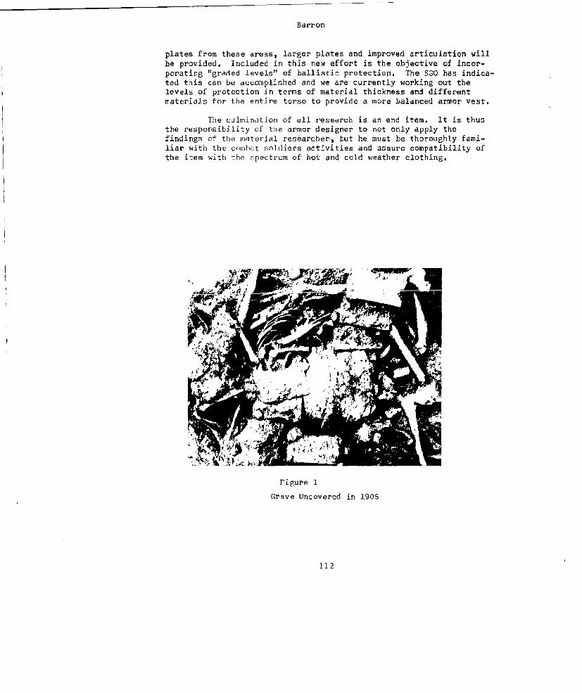
Barron
plates from these areas, larger plates and improved articulation willbe provided. Included in this new effort is the objective of incor-porating "graded levels" of ballistic protection. The SGO has indica-ted this can be accomplished and we are currently working out thelevels of protection in terms of material thickness and differentmaterials for the entire torso to provide a more balanced armor vest.
The culmination of all research is an end item. It is thusthe responsibility of the armor designer to not only apply thefindings of the naterial researcher, but he must be thoroughly fami-liar with the combat soldiers activities and assure compatibility ofthe item with the spectrum of hot and cold weather clothing.
7!
rigure I
Grave Uncovered in 1905
112
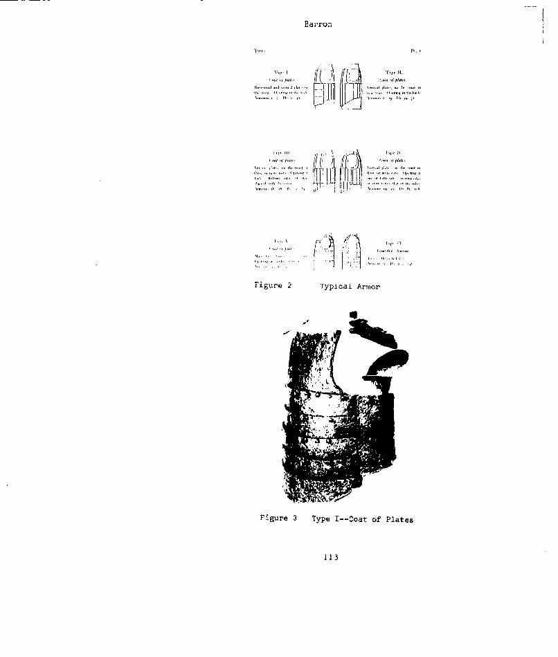
Hai'ron
'p•1, ,.",,' (lot ofJ p,;i:t
S...... . ..... ....... ...
l... ...... .I . ...
hr.
Figure 2 Typicai Armor
Figure 3 Type I--Coat of Plates
113
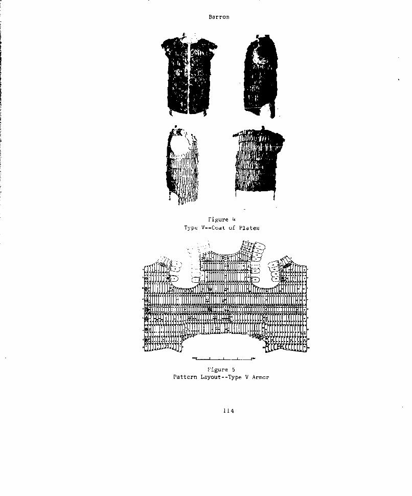
Barron
Figure 4T ype V--Coat uf Plates
tf Lr
Figur'e 5Pattern Layout--Type V Armor
114
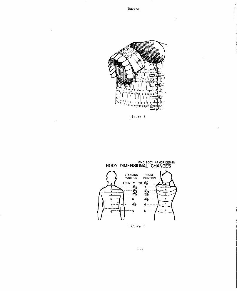
Barron
A-- ......O 3" T 0 V1 n 0-0 I0oc I
(% c
Figure 7
OM BOYARO5DSG
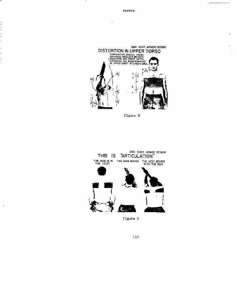
Barron
QMC BODY ARMOR DESIGNDISTORTION IN UPPER TORSO
COMPARATIVE SHADED AREASEMPHASIZE SHOULDER BREADTH
'\RECUCTION, AND CHEST DEPTHJ EXPANSION, AND DISAPPEARANCEor UPPER CHEST INTO NEC H ARA. N
03
57
E
THIS IS "ARTICULATION"THE MAN IS; IN THE MAN MOVES THE VEST MOVES
THE VEST WITH THE MAN
Figure 9
116
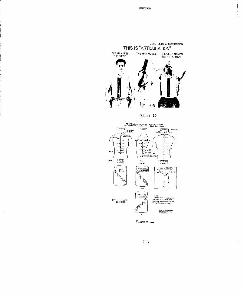
Barron
QMC BODY ARMORDESIGN
THIS IS "ARTICULATION"THE MANIS IN THE MAN MOVES THE VEST MOVES
THE VEST WITH THE MAN
Figure 10
",- ~ ~ 41 ,I-,uF IG.H 41 -
~WREAC [7IfT'S LiELID R
-r i ~SIREECHERAN COMPRESSIONOF lUMA. .S.1MO Ll
Figure ii
117

Bairron
Figure 12
Figure 13QMC Composite Armor Vest
118
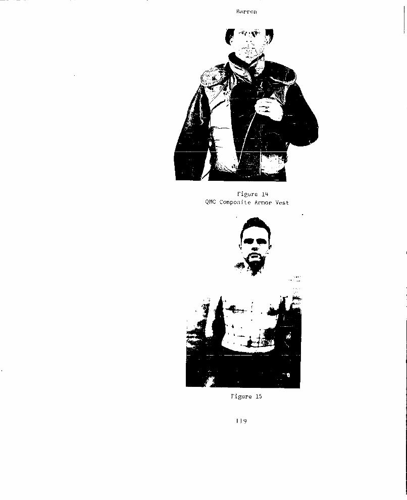
Barron
Figure 14QMC Composite Armor Vest
S2
Figure 15
119

Barron
iI,
Figure 16
Grid Distortion when Raising Arms
120
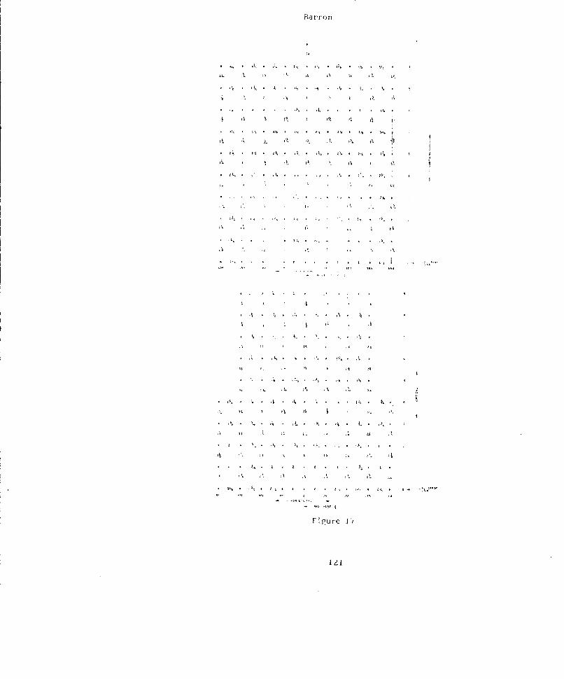
FRd rr'onr
*[ ,3 * • a K .- . ia a' ,''3 3, a i3%
., A, * ,:
4. 32 *3, f
* a, ' L * a. at *gr- 31.
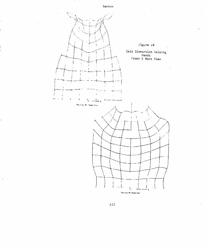
Barron
/f
[ \- \7,
Figure 18< Grid Distortion RaisingHands
Front B Back View
/ -
P -M. .-A -, VtI
7/" Th ... .",-,
_-7---
THE EFFECT OF RESIN CONCENTRATION ON PHYSICALPROPERTIES OF A LAMINATED STRUCTURE FOR A'
CRASH AND BALLISTIC PROTECTIVE FLIGHT HELMET
Abroaija L. Lastnik & John W. GatesUS Army Qunarterrnaster R & E Command
Nati-ck, Mass.
The Quartermaster Corps recently initiated a study to im-prove the crash protective cheracteristics of a helmet for Armyaircraft crewmen. 'Tis report is concerned with the effect of resinconcentration on physical properties of a nylon fabric lmilnatedstructure.
The present Army aircraft crewman's helmet has a hardshell constructed of glass fiber fabric laminated with polyesterresin. This helmet provides good crash protection but very littleballistic protection. Nylon fabric laminated with resin is 'knownto possess bailistLc resistance and good energy absorptiun propertieswhen impacted by missiles. Therefore, it was decided to investigatenylon structures as possible materials in helmet applications, whereboth b&llistic resistance and protection against low speed impactin the event of a crash were essential.
In the preliminary investigations, a ballistic resistanthelmet (1), in the shape of a conventional flight helmet with 15 - 18percent resin content, was impacted with 160 ft-lbs of energy bya striking mass wLth a velocity of 25 feet per second. The helmetappeared to absorb the energy. High speed motion pictures, however,revealed excessive transient deformation in the impact area whichcaused the helmet to bottom. Transient deformation is the deflectionof a material nnder load, which recovers rapidSly when the load isremoved. This deformation is of extremely short duration andusually caxmot be detected visually.
Although a helmet structure may appear to absorb impact
energy effectively, the occurrence of transient deformation mayat the point of impact, cause skull damage. In order to reducethis deformation the rigidity of the helmet was increased. byincreasing the percent resin from 15 - 18 percent to 35 - 40 percent.This more rigid shell was impacted with 225 ft-lbs of energy by astriking mass with a velocity of 30 feet per second. Though this
123
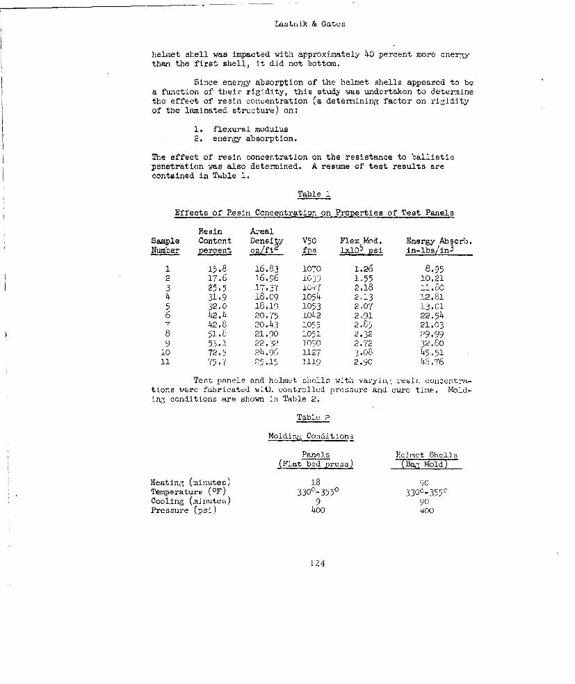
Lastnlk & Gates
helmet shell was impacted with approximately 40 percent more energythan the first shell, it did not bottom.
Since energy absorption of the helmet shells appeared to bea function of their rigidity, this study was undertaken to determinethe effect of resin concentration (a deternining factor on rigidityof the laminated structure) on:
1. flexural modulus2. energy absorption.
The effect of resin concentration on the resistance to ballisticpenetration was also determined. A resume of test results arecontained in Table 1.
Table 1
Effects of Resin Concentration on Properties of Test Panels
Resin AnnealSample Content Density V50 Flex Mod. Energy Absoro.Number percent p fs 1x10⁵ psi in-lbs/in3
1 15.8 16.83 1070 1.26 8.952 17.6 16.96 i03) 1.55 10.213 25.5 17.37 q i47 2.18 11.604 31.9 18.09 1054 2.13 12.815 32.0 18.19 1053 2.07 13.016 42.4 20.75 1042 2.91 22.547 42.8 20.43 1055 2.85 21.038 51.6 21.90 1051 2.32 29.999 53.1 22.32 1090 2.72 32.8010 72.5 24 .9L- 1127 3.08 45.5111 75.7 E5.1i 1119 2.90 46.76
Test pRnels and helmet sh'lls w-'ith varying reirn concentra-tions were fabricated with controlled pressure and cure time. Mold-ing conditions are shown in Table 2.
Table 2
Molding Conditions
Panels Yceniet Shells(Flat bed press) (BaZ Mold)
Heating (minutes) 18 90Temperature (OF) 3300-355° 3300- 3550Cooling (minutes) 9 90Pressure (psi) 400 400
124
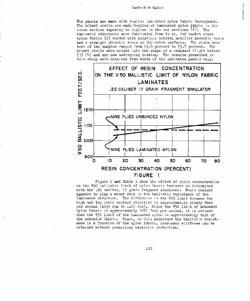
Lastnik & Gates
The panels are made with 9-plies laminated nylon fabric throughout.The helmet shells are made 9-plies of laminated nylon fabric in thecrown section tapering to 5-plies in the ear sections fl). Thelaminated structures were fabricated from 14 oz. 2x2 basket weavenylon fabric (2) bonded with polyviny:l butyral modified phenolic resinand a straight phenolic resin on the outer surfaces. The resin con-tent of the samples ranged from 15.8 percent to 75.7 percent. Thehelmet shells were molded into the shape of' a standard flight helmet(3) (4) and are now undergoing testing. The results presented inthis study were obtained from tests of the laminated panels only.
r -
EFFECT OF RESIN CONCENTRATIONON THE V50 BALLISTIC LIMIT OF NYLON FABRIC
-N LAMINATES'3 CALIBER I7 GR QA INK FRAGMKENT SaIMULATOR0
S1200
L/--_ __ _ ___ '___ N_ _- YLO__ ____ ___
4zNINE PLIES UNB DED YOF-
i 1000 •
0U) NINE PLIES LAMINATED NYLON
0 10 20 30 40 50 60 70 80
RESIN CONCENTRATION (PERCENT)FIGURE 1
Figure 1 and Table 1 show the effect of resin concentrationon the V50 ballistic limit of nylon fabric laminate as determinedwith the .22 caliber, 17 grain fragment simulator. Resin contentappears to play a minor role in the ballistic resistance of thelaminated structure. T'he difference in the V50 limit between thehigh and low resin content structure is approximately ninety feetper second (1039 fps to 1127 fps). Since the V50 limit of unbondednylon fabric is approximately 1075 feet per second, it is evidentthat the V50 limit of the laminated nylon is approximately that ofthe unbonded fabric. Since, in this structure the ballistic resist.-ance is a function of the nylon fabric, increased stiffness can beobtained without penalizing ballistic protection,
125
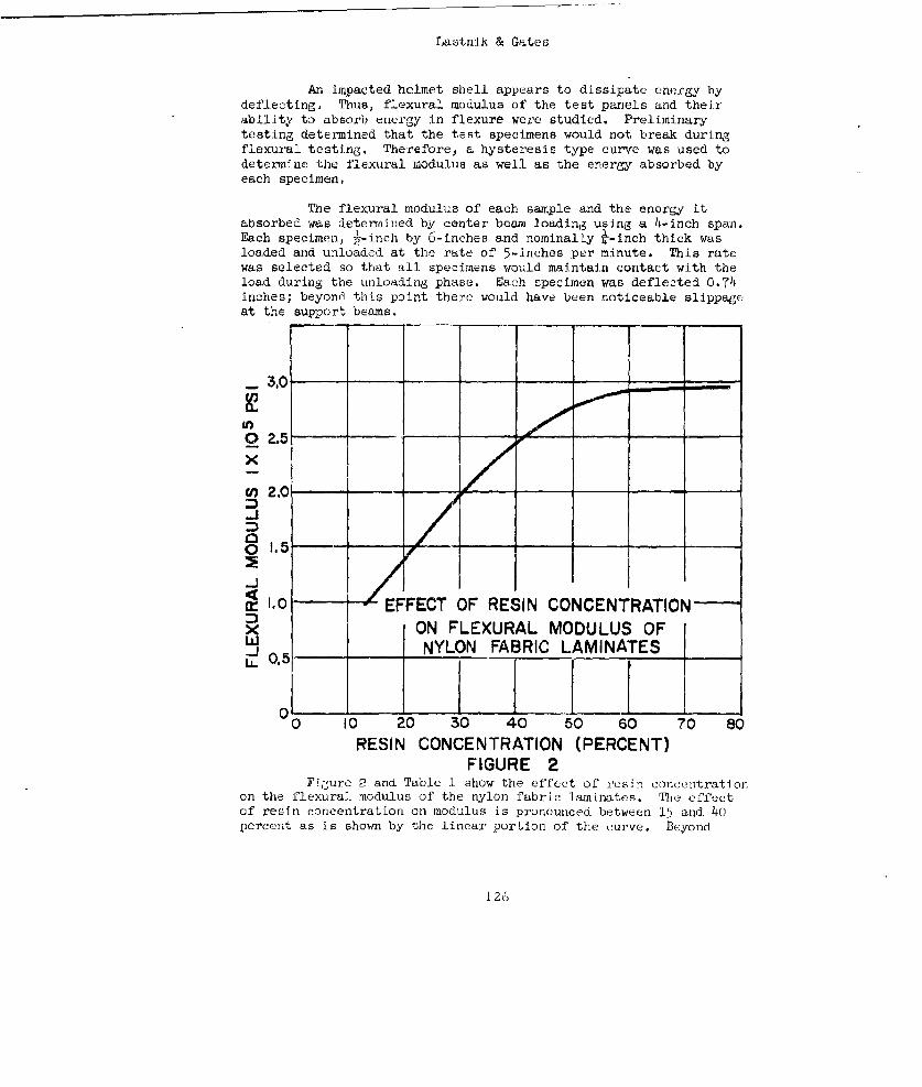
LastniX & Gates
An impacted helmet shell appears to dissipate energy bydeflecting. Thus, flexural modulus of the test panels and theirability to absorb energy in flexure were studied. Preliminarytesting determined that the test specimens would not break duringflexural testing. Therefore, a hysteresis type curve was used todetermine the flexural modulus as well as the energy absorbed byeach specimen,
The flexural modulus of each sample and the energy itabsorbed was deteyii~ned by center beam loading using a 4-inch span.Each specimen, ½-inch by 6-inches and nominally -- inch thick wasloaded and unloaded at the rate of 5-inches per minute. This ratewas selected so that all specimens would maintain contact with theload during the unloading phase. Each specimsen was deflected 0.74inches; beyond this point there would have been noticeable slippageat the support beams.
0 ,2-5 - -
XY 2.0
-J
-1o0 EFFECT OF RESIN CONCENTRATIONx ON FLEXURAL MODULUS OFLW NYLON FABRIC LAMINATES__1O.5
Oo O 20 30 40 50 60 70 80RESIN CONCENTRATION (PERCENT)
FIGURE 2Fiure 2 and Table 1 show the effect of resn concc2ntration
on the flexural modulus of the nylon fabric laminates. 'Die effectof resin concentration on modulus is pronounced between 15 and 40percent as is shown by the linear portion of the curve. Beyond
126
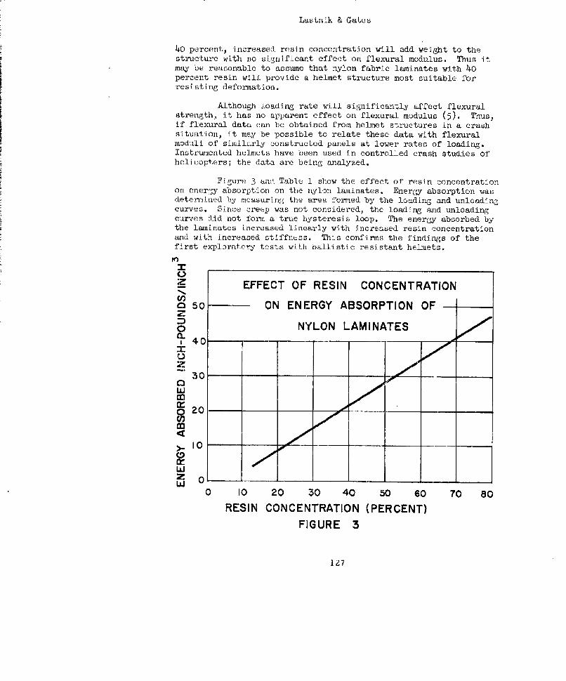
Lastnik & Gates
40 percent, increased resin concentration will add weight to thestructure with no significant effect on flexural modulus. Thus itmay be reasonable to assume that nylon fabric laminates with 40percent resin will provide a he]met structure most suitable forresisting deformation.
Although loading rate will significantly affect flexuralstrength, it has no apparent effect on flexural modulus (5). Thus,if flexural data can be obtained from helmet structures in a crashsituation, it may be possible to relate these data with flexuralmoduli of similarly constructed panels at lower rates of loading.Instrumented helmets have been used in controlled crash studies ofhelicopters; the data are being analyzed.
Figure 3 und. Table 1 show the effect of resin concentrationon ener•;y absorption on the nylon laminates. Energy absorption wasdetermined by measuring the area izermed by the loading and unloadingcurves. Since creep was not considered., the loading and unloadingcurves did not form a true hysteresis loop. The energy absorbed bythe laminates increased linearly with increased resin concentrationand with increased stiffness. This confirms the findings of thefirst explorat.or-c tests with ballistic resistant helmets.
Z EFFECT OF RESIN CONCENTRATION:Z
O 50o - ON ENERGY ABSORPTION OF
) NYLON LAMINATES,40 .. .
U
30
LaJ
Itl
0 0 00
10~
Wz Oý-W
0 10 20 30 40 50 so 70 80
RESIN CONCENTRATION (PERCENT)
FIGURE 3
12.7
Lastnik & Gates
The effect of resin concentration on hardness and on tensileproperties of the test panels will also be investigated.
The second phase of this study is the investigation of theeffect of resin concentration on the crash protective characteristicsof laminated helmet shells. Information derived from this series oftests will include energy absorption data and deflection character-istics of the helmet structures.
The findings in this report may be summarized as follows:
i. Resin content has little influence on the ballisticresistance of the aininate.
2. Energy absorbed by the laminate increases withincreased resin concentration.
3. Resin content above 40 percent will increase theweight of the laminate without significanLly affecting the flexutralmodulus.
This report is the first if a series of evaluations whichw.ll determine the physical -haracterlstics of aPbric-resin combin-ations as they are related to energy dissipation. Those character-istics found to be essential for providing crash protection will befully exploited in thi duvelopmcnt of an improved flight helmet.
128
Lastnik & "ates
References
(1) Alesi, A.L. and Landsberg, M.I., TNo Unique Plastic Helmets,Technical and Management Conference of the Reinforced FiasticsDivision, Society of' Plastics Industry, Chicago, Illinois.February 1960.
(2) Military Specification MIL-C-12369, Cloth. Nylon, Ballisticfor Arior.
(3) Military Specification MIL-H-19366, Helmet: Pilot's Protective;Type AP}I-5.
(4) Military Specification MIL-H-22995, Helmet: Pilot's Protective,qVIL~ A-PH-6_
(5) Zinzow, W.A ., Flexural Properties of Plastics, ASTM BulletinNo. 13h, May 1945.
129
A SET OF ANGLES OF OBLIQUITY FOR USE IN ASSESSING BODY ARMOR
Herbert Maisel, Wallace Chandler, and Gerald DeCarloOffice of the Quartermaster General
Department of the ArmyWashington 25, D. C.
Abstract
Measures of the effectiveness of body armor have been ob-tained in the past assuming the angle of obliquity is zero, i.e.,that the projectiles strike the armor normal to its surface. Sincepenetrability is a function of the angle of obliquity, it is importantto determine the set of angles likely to be encountered to and to usethis set when assessing body armor. An estimate of the distributionof the angles of obliquity was obtained for fraL~ents striking theupper torso. It turned out in this situation that the proportion ofangles of obliquity less than X degrees is approximately 2Xp foro: x;. 4o, (x + 4o) % for 40-<X<6o and 1O0% for X_260. The procedureused to obtain this estimate is directly applicable to making similarestimates for other parts of the body.
The paper p'e6ented by Mr. Maisel was not reproduced inthese proceedings since it is available as a published report and.may be obtained upon request from the Office of the QuartermasterGeneral, Department of the Army, Washington 25, D. C.
130
ATTENDEE-S
ABBOTT, Kenneth H. Watertown, Arsenal, Watertowni, Mass.
ABERNATHY, Leo Bureau of Naval Weapons, Department ofthe Navy, Washington 25, D. C.
AGEN, Helen E. Quartermaster Research and Engineerin,Center, Natick, Mass.
ALESr, Anthony L. Quartermaster Research and En,ineeringCenter, Natick, Mass.
AZRIN, Morris Quartermaster Resgearch and Engiineerin-Center, Natick, Mass.
BARRON, Edward R. Quartermaster Research and EngineeringCenter, Natick, Mass.
BENNETT, Lt Col Robert H. Army Research Office, Office, Chief :3fResearch and Developmaent, lash., D.C.
BERMAN, Allen Ordnance Corps, Picatinny Axsenal,Dover, Newer Jersey
BEYER, James C. Office of the Surgeon General, Dopt.of the Army, Washington 25, D. C.
BOHR, Jesse C. U. S. Army Infantry School, Ft. Bennin',Ga.
BREISCH, Kenneth E. Office of' Naval Research, Department ofthe Navy, Washington 25, D. C.
BURHNER, Alvin M. Office of the Surgeon General, Hq, U.-.Air Force, Washington 25, D. C.
COMBS, Carlton E., Jr. Hq, U. S. Continental Army CoyLmani',Fort Monroe, Virginia
COOK, Dudley Quartermaster Research and EngineeringCommand, Natick, Mass.
131
CORCORAN, John W. Beckman and ,hitley, San Carlos, Calif.
CROAN, Leonard S. Office of Chief of Ordnance (ORDTB),Department of the Arty, ',ash., D. C.
CRUGNOLA, Aldo M. Quartermaster Research and EngineerinzgCenter, Natick, Mass.
DERRICK, LeGrande 0. Naval Medical Field Research Laboratory-,Camp Lejeune, North Carolina
DUNHAM, James V. Frankford Arsenal, Philadelphia 27, Pa.
FENSTERMAKER, Carl A. National Bureau of Standards, ,ash.,D. C.
FREDERICK, E. R., jr. Mellon Institute, 4L0u Fifth Avenue,Pittsburgh 13, Pa.
FUGELSO, Leif E. American Machine and Foundry Compeay,Niles, Tllinois
GARDNER, Charles Office of the Quartermaster General,Dept. of the Armye, Washington 25, 1). C.
GAYDOS, George M. Picablrny Arsenal, Dover, New Jersey
GITHINS, Sherwood, Dr. Army Research Office, Durhaw., N. C.
GRAY, Douglas T. U. S. Naval Wesenons Laboratory,Dahlgren, Va.
HALL, Warren H. U. '. Naval .ea-oons Laboratory,Dahlgren, Va.
HARRIS, Bravid II. ll Ballistics Research Laboratories,Aberdeen Proving Gr'ound, Maryiland
HENN, Howard Ralph U. S. Naval Medical Pield Reooearch Lab.Camp Lejeune, North OarnlLnn
HODI, Frank S. datertovm Arse.nal, .atsrtin, Mase.
JASKO4SKE, MIchael C. Mellon tnstitute, 44uC{ Fifth Avenue,Pittsburg'h 13, Pennsylvania
KASDORF; Frank '.. U. S. Naval &eancns Laboratotr,Dahigren, Va.
KATLIT-, Jesse M. Frankford Arsenal, Phitadeluhia 27, Po.
132
KYMER, James R. Frankford Arsenal, Philadeophia 27, Pa.
LAIBLE, Roy C. Quartermaster Research and Enginearin>Center, Natick, Mass.
LANDSBERG, Meyer T. Quartermaster Research and EngineerLngCenter, Natick, Mass.
LAUTNIK, Abraham L. Quartermaster Research and EngineeringCenter, Natick, Mass.
LEOPOLD, Robert S. U. S. Naval Medical Field Research Lab.,Camp Lejeune, North Carolina
LEW[S, Frederick J., Jr. U. S. Naval Medical Research Institute-,Bethesda, Md.
LEY, Herbert L. Arnry Rescarch Office, Office, Chief ofResearch and Development, 4ashington, D.C.
LMACKiL, Daniel, K. Hq, U. ". Marine Corps, Department ofthe Navy, ;ashington, D. C.
MAGEAM, Sidney J. Office of Chief of Research andDcvclui ment, Depaxtnent uf Lhe Army'ash nLLon 25, D. C.
MAISEL, Herbert Office of the Quaxtermartcr General,
Dept, if the Army, .Washington 25, D. C.
MASCIAYNCA, Francis S. ..'atertowvn Arsenal, -iatertzwn, hýass.
Mc/HURTER, John C., Jr. Army Research Office, U. S. Army,Arliniton Hu.ll Station, Arlington 12, Va.
ICERRFTT, Elmer V. U. S. Army Transportation Rlesearch CommandFort Eustis, Lee Hall, Va.
MENARD, David U. S. Naval Medical Resc..rct. [InstituteBethesda, Md.
MORGAN, Henry M. National Academy Df Sc*ences, NationalResearch Councii, */ashingto;n, D. C.
MUDOCK, John F., Jr. Guaxtenmaster Board, U. S. Army
Fort Lee, Va.
MYERS, Keith A. Ballistics Research Laboratories,Aberdecn Proving Ground, Md.
133
NOBLE, Richard F. Marine Corps Landing Force DevelopmentCenter, Equipment Board, Quantico, Va.
ODDY, Robert V. Office of Naval Research, Department ofthe Navy, Washington, D. C.
OGILVIE, Bruce C. Marine Corps Landing Force DevelopmentCenter, Marine Corps Schools, Quantico,Va.
PLESS, William C. Ballistics Research LaboratoriesAberdeen Proving Ground, Md.
QUINLAX, John F. U. S. Naval Medical Field Research Lab.Camp Lojeune, North Carolina
SEERY, Thomas J. Bureau of Supplies and Accounts, Dept.of the Navy, Washington 25, D. C.
SCHIEFER, Herbert F. National. Bureau of Standards, Washington,D. C.
SCHAUB, W. K. Ofiice of Naval Research, Dept. of theNavy, dashington, D. C.
SHOUSE, Paul National Pureau of Standards, .-iashinCton,D. C.
SMITH, Harvey N. Hq, U. S. Marine Corps, Departmont cf" theNavy, Washington, D. C.
SMITH, Jack C. National Bureaa of Standards, .!ashin6t.n,D. C.
SPERRAZZA, Joseph Ballistics Research Lab.)ratorlesAberdeen Proving Ground, Md.
STALLMfAN, Arnold S. U. S. Armiy Infantry School, Ft. Benning,Ga.
STEWART, George M. Arrm, Chemical Center, Edgewood Arsenal,Maryland
TANEHOLTZ, Stanley D. Quartermaster Research and Engineerin-Center, Natick, Mass.
TARR, Allan L. Office of ChLef o)f Research andDevelopment, Depar'tment of the Axrmy,Washington 25, D. C.
134
TERPENITY, Russell Q~uartermnaster Board, U. S. f 'r~,i'.:,rtLee, Va.
WARýEHAM, Geor-le B. Off Lce of Defense Research and E:nrJ.ne,--.rIn._Depsartment of' Defense, ;*I.sE.hLngton 25, D.'.
'.IELNSiOCK, Lionel I.* U. S. Naval Su[)-ply Center, Beynnne, F!. J.
WTrI, David H~ampton BalJA stics Research baborutoriesý,
Aberdeen Proving Ground, MN.d
NAVAL i~fS1C1LAB
Yrw~rn, Ge RrH
Sanders, 'CI. 11.
TrenL, 'I -
SnLpes, T. G., Maj. U'H.1C
Sm~ith, P. L.
M';cKitnney, Karl 2.
Iwin,,, H. 0. Jr.
McCL:-nely, D. P.
'Alffer, Arthur
1 35


![S23 415S23 415 m//e ARMED SERVICES TECHNICAL INFORMATON AGENCY ARLINGTON HALL STATION ARLINGTON 12, VIRGINIA U N C #-AS S ]R FRI E D. NOTICE: When government or other drawings, speci](https://img.pdfslide.net/doc/110x75/60c7b2bad7ea5b7a9c001b6e/s23-415-s23-415-me-armed-services-technical-informaton-agency-arlington-hall-station.jpg)