Embed Size (px)
Citation preview

FIA Anexo J / Appendix J – Art.253
FIA Sport / Departamento Técnico 1/19 CMDA / WMSC 11.12.2009 FIA Sport / Technical Department Publicado el / Published on 16.12.2009
Artículo 253 - 2010
Equipamiento de Seguridad / Safety Equipment (Grupos N, A, B, SP / Groups N, A, B, SP)
Modificación del Artículo 16.6 publicado el 16.12.2009
Modification of Article 16.6 published on 16.12.2009
ARTÍCULO 1: Los Comisarios Deportivos podrán excluir a un vehículo cuya construcción parezca presentar peligro. ARTÍCULO 2: Si un dispositivo fuera opcional, deberá estar montado conforme a los reglamentos. ARTÍCULO 3: CANALIZACIONES Y BOMBAS 3.1 Protección Las conducciones de combustible, aceite y frenos deben estar protegidas externamente contra cualquier riesgo de deterioro (piedras, corrosión, roturas mecánicas, etc.), e internamente contra todo riesgo de incendio y de deterioro. Aplicación: Opcional para Grupo N, si se conserva la instalación de origen. Obligatorio para todos los grupos, si no se mantiene la instalación de serie, o si las canalizaciones pasan por el interior del coche y han sido retirados los materiales que las protegen. En el caso de canalizaciones de combustible, las partes metálicas que están aisladas de la carrocería, por piezas o elementos no conductores, deben conectarse eléctricamente a ella. 3.2 Especificaciones e instalación Aplicación obligatoria si la instalación de serie no se conserva. Las canalizaciones de agua de refrigeración o de aceite de lubricación deben ser exteriores al habitáculo. Las instalaciones de las canalizaciones de carburante, de aceite de lubricación y las que contengan fluido hidráulico a presión deben ser construidas de acuerdo a las siguientes especificaciones: - si son flexibles, estas conexiones deben tener racores roscados, engastados o autoobturantes y un trenzado exterior resistente a la abrasión y al fuego (que no mantenga la combustión); - deberán soportar una presión mínima medida a una temperatura de trabajo mínima de: - Canalizaciones de combustible (salvo las conexiones a los inyectores y el radiador de refrigeración en el circuito de retorno al depósito): 70 bar (1000 psi) 135°C (250°F). - Canalizaciones de aceite lubricante: 70 bar (1000 psi) 232℃ (232,22℃). - Canalizaciones conteniendo fluido hidráulico bajo presión: 280 bar (4000 psi) 232℃ (232,22℃). Si la presión de funcionamiento del sistema hidráulico es superior a 140 bar (2000 psi), la presión que debe soportar deberá ser al menos el doble de la presión de funcionamiento. Las canalizaciones de combustible y de fluido hidráulico podrán pasar por el habitáculo pero sin presentar racores o conexiones menos cuando las paredes delantera y trasera se hayan realizado según los dibujos 253-59 y 253-60 y excepto sobre el circuito de frenos y el circuito de líquido de embrague.
ARTICLE 1: A car, the construction of which is deemed to be dangerous, may be excluded by the Stewards of the meeting. ARTICLE 2: If a device is optional, it must be fitted in a way that complies with regulations. ARTICLE 3: LINES AND PUMPS 3.1 Protection Fuel, oil and brake lines must be protected externally against any risk of deterioration (stones, corrosion, mechanical breakage, etc.) and internally against all risks of fire and deterioration. Application: Optional for Group N if the series production fitting is retained. Obligatory for all the Groups if the series production fitting is not retained or if the lines pass inside the vehicle and their protective covering has been removed. In the case of fuel lines, the metal parts which are isolated from the shell of the car by non-conducting parts must be connected to it electrically. 3.2 Specifications and installation Obligatory application if the series fitting is not retained. Lines containing cooling water or lubricating oil must be outside the cockpit. The fittings of fuel lines, lubricating oil lines and of those containing hydraulic fluid under pressure must be manufactured according to the specifications below: - when flexible, these lines must have threaded, crimped or self-sealing connectors and an outer braid resistant to abrasion and flame (will not sustain combustion); - minimum burst pressure measured at a minimum operating temperature of: - Fuel lines (except the connections to the injectors and the cooling radiator on the circuit returning to the tank): 70 bar (1000 psi) 135°C (250°F). - Lubricating oil lines: 70 bar (1000 psi) 232°C (450°F). - Lines containing hydraulic fluid under pressure: 280 bar (4000 psi) 232°C (450°F). If the operating pressure of the hydraulic system is greater than 140 bar (2000 psi), the burst pressure must be at least double the operating pressure. Lines containing fuel or hydraulic fluid may pass through the cockpit, but without any connectors inside except on the front and rear bulkheads according to Drawings 253-59 and 253-60, and on the braking circuit and the clutch fluid circuit.
253-59
253-60
3.3 Corte de combustible automático Recomendado para todos los Grupos:
3.3 Automatic fuel cut-off Recommended for all groups:

FIA Anexo J / Appendix J – Art.253
FIA Sport / Departamento Técnico 2/19 CMDA / WMSC 11.12.2009 FIA Sport / Technical Department Publicado el / Published on 16.12.2009
Todas las conducciones de combustible que alimentan al motor deben estar provistas con válvulas de corte automático situadas directamente en el depósito de combustible que cierren automáticamente todas las canalizaciones de combustible presurizadas si una de esas conducciones se rompe o tiene fugas. Obligatorio: Todas las bombas de combustible deben funcionar solamente cuando el motor está en marcha, excepto durante el proceso de arranque. 3.4 Ventilación del depósito de combustible El conducto de ventilación del depósito de combustible así como las válvulas descritas más abajo deben tener las mismas especificaciones que las conducciones de gasolina (artículo 3.2) y deben estar equipadas con un sistema que cumpla con las siguientes especificaciones: - Válvula antivuelco activada por la Gravedad - Válvula de ventilación de flotador - Válvula de sobrepresión tarada a una presión máxima de 200 mbar, que funcione cuando la válvula de ventilación de flotador esté cerrada. ARTÍCULO 4: SEGURIDAD DE FRENADO Doble circuito accionado por el mismo pedal: La acción del pedal se ejercerá, normalmente, sobre todas las ruedas; en caso de fuga en cualquier punto de las conducciones del sistema de frenos o de cualquier fallo en el sistema de transmisión de los frenos, el pedal debe controlar, al menos 2 ruedas. Aplicación: Si se mantiene el sistema de serie, no son necesarias modificaciones. ARTÍCULO 5: FIJACIONES SUPLEMENTARIAS Al menos se instalarán dos fijaciones suplementarias para cada uno de los capós. Los mecanismos de cierre originales deberán dejarse inoperantes o desmontarse. Aplicación: Opcional para Grupo N, obligatorio para los otros grupos. Los objetos grandes llevados a bordo del vehículo (como la rueda de repuesto, caja de herramientas, etc.), deben estar firmemente sujetos. ARTÍCULO 6: CINTURONES DE SEGURIDAD 6.1 Arneses Utilización de dos bandas para los hombros y una banda abdominal; puntos de anclaje a la carrocería: dos para la banda abdominal, dos para las bandas de los hombros. Estos arneses deben estar homologados por la FIA y cumplir con las Normas FIA nº 8854/98 o 8853/98. Además, los arneses utilizados en pruebas de circuito deben estar equipados de un sistema de apertura por hebilla giratoria. Para rallyes, deben llevarse a bordo dos cutters en todo momento. Deben ser fácilmente accesibles para el piloto y el copiloto estando sentados con los arneses abrochados. Por el contrario, se recomienda que para pruebas que incluyan recorridos sobre carretera abierta el sistema de apertura sea de pulsador. Las ADN podrán homologar puntos de anclaje a la estructura de seguridad cuando esta estructura se esté homologando, a condición de que estos sean probados. 6.2 Instalación Está prohibido anclar los arneses a los asientos o sus soportes. Un arnés de seguridad puede instalarse sobre los puntos de anclaje del vehículo de serie. Las ubicaciones geométricas recomendadas para los puntos de anclaje se muestran en el dibujo nº 253-61.
All fuel feed pipes going to the engine must be provided with automatic cut-off valves located directly on the fuel tank which automatically close all the fuel lines under pressure if one of these lines in the fuel system is fractured or leaks. Compulsory: All the fuel pumps must only operate when the engine is running, except during the starting process. 3.4 Fuel cell ventilation The ventilation line of the fuel cell as far as the valves described below must have the same specifications as those of the fuel lines (article 3.2) and must be fitted with a system complying with the following conditions: - Gravity activated roll-over valve - Float chamber ventilation valve - Blow-off valve with a maximum over pressure of 200 mbar, working when the float chamber ventilation valve is closed. ARTICLE 4: BRAKING SAFETY SYSTEM Double circuit operated by the same pedal: the pedal shall normally control all the wheels; in case of a leakage at any point of the brake system pipes or of any kind of failure in the brake transmission system, the pedal shall still control at least two wheels. Application: If this system is fitted in series production, no modifications are necessary. ARTICLE 5: ADDITIONAL FASTENERS At least two additional safety fasteners must be fitted for each of the bonnet and boot lids. The original locking mechanisms will be rendered inoperative or removed. Application: Optional for Group N, obligatory for the other Groups. Large objects carried on board the vehicle (such as the spare wheel, tool-kit, etc.) must be firmly fixed. ARTICLE 6: SAFETY BELTS 6.1 Belts Wearing of two shoulder straps and one lap strap ; anchorage points on the shell: two for the lap strap, two for the shoulder straps. These belts must be homologated by the FIA and comply with FIA standard n°8853/98 or 8854/98. Furthermore, the belts used in circuit competitions must be equipped with turnbuckle release systems. For rallies, two belt cutters must be carried on board at all times. They must be easily accessible for the driver and co-driver when seated with their harnesses fastened. On the other hand, it is recommended that for competitions which include public road sections, the belts be equipped with push button release systems. The ASNs may homologate mounting points on the safety cage when this cage is being homologated, on condition that they are tested. 6.2 Installation It is prohibited for the seat belts to be anchored to the seats or their supports. A safety harness may be installed on the anchorage points of the series car. The recommended geometrical locations of the anchorage points are shown in Drawing n° 253-61.
253-61

FIA Anexo J / Appendix J – Art.253
FIA Sport / Departamento Técnico 3/19 CMDA / WMSC 11.12.2009 FIA Sport / Technical Department Publicado el / Published on 16.12.2009
Las bandas de los hombros deben estar dirigidas hacia atrás y hacia abajo y deben instalarse de tal forma que no formen un ángulo mayor de 45º con la horizontal, a partir del borde superior del respaldo, aunque se recomienda que este ángulo no supere los 10º. Los ángulos máximos con relación al eje del asiento son 20º divergentes o convergentes. Si es posible, deberá utilizarse el punto de anclaje originalmente previsto por el constructor sobre el montante C. Los puntos de anclaje que impliquen un ángulo con la horizontal más elevado no deberán usarse. En este caso, las bandas de los hombros de los arneses de 4 puntos podrán instalarse en los puntos de anclaje de las bandas abdominales de los asientos traseros instalados de origen por el constructor del vehículo. Para un arnés de 4 puntos, las bandas de los hombros deben instalarse de forma que se crucen simétricamente con relación al eje del asiento delantero. Las bandas abdominales y pélvicas no deben pasar sobre los lados del asiento ni a través del mismo, con el fin de envolver y sujetar la región pélvica sobre la mayor área posible. Las bandas abdominales deben ajustarse estrechamente en la unión de la cresta pélvica y la parte superior del muslo. Bajo ningún concepto deben utilizarse sobre la zona abdominal. Se debe evitar que las bandas se dañen al rozarse por el uso contra aristas vivas. - Si la instalación en los puntos de anclaje de serie fuese imposible para las bandas de los hombros y pélvicas, deben instalarse nuevos puntos de anclaje en la carrocería o el chasis, lo más cerca posible del eje de las ruedas traseras para las bandas de los hombros. Las bandas de los hombros pueden fijarse, igualmente, a la estructura de seguridad o a una barra de refuerzo por medio de un lazo, o bien, fijarse a los anclajes superiores de los cinturones traseros, o apoyarse o fijarse en un refuerzo transversal soldado a los tirantes longitudinales de la estructura (ver dibujo 253-66).
In the downwards direction, the shoulder straps must be directed towards the rear and must be installed in such a way that they do not make an angle of more than 45° to the horizontal from the upper rim of the backrest, although it is recommended that this angle should not exceed 10°. The maximum angles in relation to the centre-line of the seat are 20° divergent or convergent. If possible, the anchorage point originally mounted by the car manufacturer on the C-pillar should be used. Anchorage points creating a higher angle to the horizontal must not be used. In that case, the shoulder straps of 4-point safety harnesses may be installed on the rear seat lap strap anchorage points originally mounted by the car manufacturer. For a 4-point harness, the shoulder straps must be installed crosswise symmetrically about the centre-line of the front seat. The lap and crotch straps should pass not over the sides of the seat but through the seat, in order to wrap and hold the pelvic region over the greatest possible surface. The lap straps must fit tightly in the bend between the pelvic crest and the upper thigh. Under no conditions must they be worn over the region of the abdomen. Care must be taken that the straps cannot be damaged through chafing against sharp edges. - If installation on the series anchorage points is impossible for the shoulder and/or crotch straps, new anchorage points must be installed on the shell or the chassis, as near as possible to the centre-line of the rear wheels for the shoulder straps. The shoulder straps may also be fixed to the safety cage or to a reinforcement bar by means of a loop, and may also be fixed to the top anchorage points of the rear belts, or be fixed or leaning on a transversal reinforcement welded between the backstays of the cage (see Drawing 253-66).
253-66
En este caso, el uso de un refuerzo transversal está sujeto a las siguientes condiciones: - El refuerzo transversal será un tubo de, al menos, 38 mm x 2,5 mm o 40 mm x 2 mm de acero al carbono estirado en frío sin soldadura, con una resistencia mínima a la tracción de 350 N/mm2. - La altura de este refuerzo será tal que las bandas de los hombros, hacia atrás, están dirigidas hacia abajo con un ángulo de entre 10º y 45º con la horizontal desde el borde del respaldo, se recomienda un ángulo de 10º. - Se autoriza a fijar las bandas por medio de un lazo o por tornillos, pero en este último caso debe soldarse una pieza por cada punto de anclaje (ver dibujo 253-67 para las dimensiones).
In this case, the use of a transversal reinforcement is subject to the following conditions: - The transversal reinforcement shall be a tube measuring at least 38 mm x 2.5 mm or 40 mm x 2 mm, made from cold drawn seamless carbon steel, with a minimum tensile strength of 350 N/mm2. - The height of this reinforcement must be such that the shoulder straps, towards the rear, are directed downward with an angle of between 10° and 45° to the horizontal from the rim of the backrest, an angle of 10° being recommended. - The straps may be attached by looping or by screws, but in the latter case an insert must be welded for each mounting point (see Drawing 253-67 for the dimensions).
253-67
Estas piezas se situarán en la barra de refuerzo y las bandas estarán fijadas a ellos por medio de tornillos M12 8.8 o 7/16 UNF. - Cada punto de anclaje deberá resistir una carga de 1.470 daN, o 720 daN para las bandas pélvicas.
These inserts will be positioned in the reinforcement tube and the straps will be attached to them using bolts of M12 8.8 or 7/16UNF specification. - Each anchorage point must be able to withstand a load of 1470 daN, or 720 daN for the crotch straps.

FIA Anexo J / Appendix J – Art.253
FIA Sport / Departamento Técnico 4/19 CMDA / WMSC 11.12.2009 FIA Sport / Technical Department Publicado el / Published on 16.12.2009
En el caso de un punto de anclaje para dos bandas (prohibido para las bandas de los hombros), la carga considerada será igual a la suma de las dos cargas requeridas. - Para cada nuevo punto de fijación creado, se utilizará una placa de refuerzo en acero con una superficie de, al menos, 40 cm2 y un espesor de, al menos, 3 mm. - Principios de fijación sobre el chasis/monocasco: 1) Sistema de fijación general: ver dibujo 253-62.
In the case of one anchorage point for two straps (prohibited for shoulder straps), the load considered will be equal to the sum of the required loads. - For each new anchorage point created, a steel reinforcement plate with a surface area of at least 40 cm2 and a thickness of at least 3 mm must be used. - Principles of mounting to the chassis / monocoque: 1) General mounting system: see Drawing 253-62.
253-62
2) Sistema de fijación para las bandas de los hombros: ver dibujo 253-63.
2) Shoulder strap mounting: see Drawing 253-63.
253-63
3) Sistema de fijación para las bandas pélvicas: ver dibujo 253-64. 3) Crotch strap mounting: see Drawing 253-64.
253-64
6.3 Utilización Un arnés debe usarse en su configuración de homologación sin ninguna modificación o eliminación de piezas, y en conformidad con las instrucciones del fabricante. La eficacia y duración de los cinturones de seguridad está directamente relacionada con la forma en la que se instalan, usan y mantienen. Los cinturones deben reemplazarse después de un accidente serio, si se encuentran cortados, deshilachados o debilitados debido a la acción de la luz del Sol o de productos químicos. También deben cambiarse si las piezas de metal o las hebillas están deformadas, dobladas o corroídas. Todo arnés que no funcione correctamente debe sustituirse. ARTÍCULO 7: EXTINTORES - SISTEMAS DE EXTINCIÓN El uso de los siguientes productos estará prohibido: BCF, NAF. 7.1 En rallyes: Aplicación de los artículos 7.2 y 7.3. En pruebas de circuito, slalom y montaña:
6.3 Use A safety harness must be used in its homologation configuration without any modifications or removal of parts, and in conformity with the manufacturer's instructions. The effectiveness and longevity of safety belts are directly related to the manner in which they are installed, used and maintained. The belts must be replaced after every severe collision, and whenever the webbing is cut, frayed or weakened due to the actions of chemicals or sunlight. They must also be replaced if metal parts or buckles are bent, deformed or rusted. Any harness which does not function perfectly must be replaced. ARTICLE 7: EXTINGUISHERS – EXTINGUISHING SYSTEMS The use of the following products is prohibited: BCF, NAF. 7.1 In rallies: Articles 7.2 and 7.3 apply. In circuit events, slaloms, hillclimbs:

FIA Anexo J / Appendix J – Art.253
FIA Sport / Departamento Técnico 5/19 CMDA / WMSC 11.12.2009 FIA Sport / Technical Department Publicado el / Published on 16.12.2009
Aplicación de los artículos 7.2 ó 7.3. 7.2 Sistemas instalados 7.2.1) Todos los vehículos deben estar equipados con un sistema de extinción que figure en la lista técnica nº 16: "Sistemas de extinción homologados por la FIA". 7.2.2) Todos los extintores deberán protegerse adecuadamente y estar situados en el habitáculo. En todos los casos, sus fijaciones serán capaces de soportar una deceleración de 25 g. Todo el equipo de extinción debe ser resistente al fuego. Las conducciones de plástico están prohibidas y las conducciones de metal son obligatorias. 7.2.3) El piloto debe ser capaz de accionar todos los extintores manualmente cuando esté sentado normalmente con sus cinturones puestos y el volante en su sitio. Además, debe combinarse un interruptor de accionamiento externo con un cortacorrientes, o situarse cerca de él. Debe estar identificado con una letra “E” en rojo dentro de un círculo blanco con el borde rojo, de un diámetro mínimo de 10 cm. Para vehículos WRC, el accionamiento de interruptor de un extintor exterior o interior debe traer consigo el corte de suministro eléctrico de la batería y el motor. 7.2.4) El sistema debe funcionar en todas las posiciones. 7.2.5) Las toberas de extinción deben ser las adecuadas al agente extintor e instalarse de tal manera que no apunten directamente a la cabeza de los ocupantes. 7.3 Extintores manuales 7.3.1) Todos los coches deben estar equipados con uno o dos extintores. 7.3.2) Agentes extintores permitidos: AFFF, FX G-TEC, Viro 3, polvo o cualquier otro agente extintor homologado por la FIA. 7.3.3) Cantidad mínima de agente extintor: AFFF: 2,4 litros FX G-TEC: 2,0 kg Viro 3: 2,0 kg Zero 360: 2,0 kg Polvo: 2,0 kg 7.3.4) Todos los extintores deben estar presurizados en función de su contenido como sigue: AFFF: de acuerdo con las instrucciones del fabricante. FX G-TEC y Viro3: de acuerdo con las instrucciones del fabricante. Zero 360: de acuerdo con las instrucciones del fabricante. Polvo: 8 bar mínimo y 13,5 bar máximo. Además, en el caso de los AFFF, los extintores deberán estar equipados con un sistema que permita la verificación de la presión del contenido. 7.3.5) La información siguiente deberá figurar visiblemente en cada extintor: - Capacidad - Tipo de agente extintor - Peso o volumen del agente extintor - Fecha en la que debe revisarse el extintor, que no debe ser más de dos años después de la fecha de llenado o última revisión, o bien la fecha límite de validez correspondiente. 7.3.6) Todos los extintores deben estar protegidos adecuadamente. Sus fijaciones deben ser capaces de soportar deceleraciones de 25 g. Además, solo se aceptarán (dos como mínimo) las fijaciones metálicas de desprendimiento rápido con abrazaderas metálicas. 7.3.7) Los extintores deben ser fácilmente accesibles al piloto y copiloto. ARTÍCULO 8: ESTRUCTURA DE SEGURIDAD 8.1 Generalidades: La instalación de una estructura de seguridad es obligatoria. Debe estar: a) Fabricada de acuerdo a los requerimientos de los artículos siguientes; b) Homologada o certificada por una ADN de acuerdo a los reglamentos de homologación para estructuras de seguridad; Se debe presentar a los Comisarios Técnicos de la prueba una copia original del documento o certificado de homologación aprobado por la ADN y firmado por técnicos cualificados que representen al fabricante. Toda nueva estructura de seguridad homologada por una ADN y vendida a partir del 01/01/2003, deberá estar identificada, de forma individual, por una placa de identificación colocada por el
Article 7.2 or 7.3 applies. 7.2 Systems mounted 7.2.1) All cars must be equipped with an extinguishing system from technical list n°16: "Extinguisher systems homologated by the FIA". 7.2.2) All extinguishers must be adequately protected and must be situated within the cockpit. In all cases their mountings must be able to withstand a deceleration of 25 g. All extinguishing equipment must withstand fire. Plastic pipes are prohibited and metal pipes are obligatory. 7.2.3) The driver must be able to trigger all extinguishers manually when seated normally with his safety belts fastened and the steering wheel in place. Furthermore, a means of triggering from the outside must be combined with the circuit-breaker switch. It must be marked with a letter "E" in red inside a white circle of at least 10 cm diameter with a red edge. For WRC type cars, the triggering of an external or internal extinguisher must compulsorily bring about engine and battery cut-off. 7.2.4) The system must work in all positions. 7.2.5) Extinguisher nozzles must be suitable for the extinguishant and be installed in such a way that they are not directly pointed at the occupants' heads. 7.3 Manual extinguishers 7.3.1) All cars must be fitted with one or two fire extinguishers. 7.3.2) Permitted extinguishants: AFFF, FX G-TEC, Viro3, powder or any other extinguishant homologated by the FIA. 7.3.3) Minimum quantity of extinguishant: AFFF: 2.4 litres FX G-TEC: 2.0 kg Viro3: 2.0 kg Zero 360 2,0 kg Powder: 2.0 kg 7.3.4) All extinguishers must be pressurised according to the contents: AFFF: in accordance with the manufacturer's instructions FX G-TEC and Viro3: in accordance with the manufacturer's instructions Zero 360: in accordance with the manufacturer's instructions Powder: 8 bar minimum, 13.5 bar maximum Furthermore, each extinguisher when filled with AFFF must be equipped with a means of checking the pressure of the contents. 7.3.5) The following information must be visible on each extinguisher: - capacity - type of extinguishant - weight or volume of the extinguishant - date the extinguisher must be checked, which must be no more than two years after either the date of filling or the date of the last check, or corresponding expiry date. 7.3.6) All extinguishers must be adequately protected. Their mountings must be able to withstand a deceleration of 25 g. Furthermore, only quick-release metal fastenings (two minimum), with metal straps, will be accepted. 7.3.7) The extinguishers must be easily accessible for the driver and the co-driver. ARTICLE 8: SAFETY CAGES 8.1 General: The fitting of a safety cage is compulsory. It may be either: a) Fabricated in compliance with the requirements of the following articles; b) Homologated or Certified by an ASN according to the homologation regulations for safety cages; An authentic copy of the homologation document or certificate, approved by the ASN and signed by qualified technicians representing the manufacturer, must be presented to the event's scrutineers. Any new cage which is homologated by an ASN and is on sale, as from 01.01.2003, must be identified by means of an identification plate affixed to it by the manufacturer; this identification plate must

FIA Anexo J / Appendix J – Art.253
FIA Sport / Departamento Técnico 6/19 CMDA / WMSC 11.12.2009 FIA Sport / Technical Department Publicado el / Published on 16.12.2009
constructor que no pueda copiarse ni retirarse (es decir, soldada, troquelada o un adhesivo auto destructible). La placa de identificación debe portar el nombre del constructor, el número de homologación de la ADN y el número de serie único del fabricante. Deberá llevarse a bordo un certificado mostrando los mismos números identificativos y presentarse a los comisarios técnicos de la prueba. c) Homologada por la FIA de acuerdo a los reglamentos de homologación para estructuras de seguridad. Esta estructura de seguridad debe ser objeto de una extensión (VO) de la ficha de homologación del vehículo homologado por la FIA. La identificación del fabricante y un número de serie debe ser claramente visible en todas las estructuras homologadas y vendidas desde el 1 de enero de 1997. La ficha de homologación de la estructura debe especificar cómo y dónde se indica esta información, y los compradores deben recibir un certificado numerado correspondiente a la misma. Para los siguientes vehículos, la estructura de seguridad debe estar homologada por FIA: Variante Kit Súper 1600, Variante Kit Súper 2000, Variante Kit Súper 2000 Rallye, Variante World Rallye Car. Toda modificación de una estructura de seguridad homologada o certificada está prohibida. Será considerado como modificación cualquier proceso sobre la estructura por medio de mecanizado o soldadura que implique una modificación permanente del material o de la estructura de seguridad. Cualquier reparación de una estructura de seguridad dañada tras un accidente debe llevarse a cabo por el fabricante de la estructura o con su aprobación. Los tubos de las estructuras de seguridad no deben transportar fluidos ni ninguna otra cosa. Las estructuras de seguridad no deben dificultar la entrada o salida del piloto y copiloto. Los elementos de la estructura podrán ocupar el espacio de los ocupantes atravesando el salpicadero y los revestimientos delanteros, así como el asiento y revestimientos traseros. Los asientos traseros pueden plegarse. 8.2 Definiciones: 8.2.1 Estructura de seguridad: Estructura multitubular instalada en el habitáculo cerca de la carrocería, concebida con el fin de evitar una deformación importante de la carrocería (chasis) en caso de accidente. 8.2.2 Arco de seguridad: Estructura tubular formando un arco con dos bases de anclaje. 8.2.3 Arco principal (dibujo 253-1): Estructura prácticamente vertical constituida por un arco tubular de una sola pieza (inclinación máxima +/-10° con respecto a la vertical) situado en un plano transversal al vehículo, e inmediatamente detrás de los asientos delanteros. 8.2.4 Arco delantero (dibujo 253-1): Similar al arco principal pero su forma sigue los montantes y el borde superior del parabrisas 8.2.5 Arco lateral (dibujo 253-2): Estructura casi longitudinal y prácticamente vertical constituida por un arco tubular de una sola pieza, situado a lo largo de la parte derecha o izquierda del vehículo, siguiendo el pilar delantero del mismo el montante del parabrisas, y los montantes traseros siendo casi verticales y estando justo detrás de los asientos delanteros. 8.2.6 Semiarco lateral (dibujo 253-3): Idéntico al arco lateral pero sin el pilar trasero. 8.2.7 Tirante longitudinal: Tubo casi longitudinal uniendo las partes superiores del arco principal y delantero. 8.2.8 Tirante transversal: Tubo semi-transversal que une los miembros superiores de los arcos o semiarcos laterales. 8.2.9 Tirante diagonal: Tubo transversal que une uno de los ángulos superiores del arco principal o uno de los extremos del miembro transversal en el caso de un arco lateral, y el pie de anclaje opuesto inferior del arco o El extremo superior de un tirante trasero con el punto de anclaje inferior del otro tirante trasero.
be neither copied nor moved (i.e. embedded, engraved or self-destroying sticker). The identification plate must bear the name of the manufacturer, the homologation or certification number of the ASN homologation form or certificate and the individual series number of the manufacturer. A certificate bearing the same numbers must be carried on board and be presented to the event's scrutineers. c) Homologated by the FIA according to the homologation regulations for safety cages. It must be the subject of an extension (VO) to the homologation form of the vehicle homologated by the FIA. The manufacturer's identification and a series number must be clearly visible on all cages homologated and sold after 01.01.1997. The homologation form of the cage must specify how and where this information is indicated, and the purchasers must receive a numbered certificate corresponding to this. For the following cars, the cage must compulsorily be homologated by the FIA: Super 1600 Kit Variant, Super 2000 Kit Variant, Super 2000 Rally Kit Variant, World Rally Car Variant. Any modification to a homologated or certified safety cage is forbidden. To be considered as a modification, any process made to the cage by machining, welding, that involves a permanent modification of the material or the safety cage. All repairs to a homologated or certified safety cage, damaged after an accident must be carried out by the manufacturer of the rollcage or with his approval. Tubes must not carry fluids or any other item. The safety cage must not unduly impede the entry or exit of the driver and co-driver. Members may intrude into the occupant's space in passing through the dashboard and trim, as well as through the rear seats. The rear seat may be folded down. 8.2 Definitions: 8.2.1 Safety cage: Multi-tubular structure installed in the cockpit and fitted close to the bodyshell, the function of which is to reduce the deformation of the bodyshell (chassis) in case of an impact. 8.2.2 Rollbar: Tubular frame forming a hoop with two mounting feet. 8.2.3 Main rollbar (drawing 253-1): Transversal and near-vertical (maximum angle +/-10° to the vertical) single piece tubular hoop located across the vehicle just behind the front seats. 8.2.4 Front rollbar (drawing 253-1): Similar to main rollbar but its shape follows the windscreen pillars and top screen edge. 8.2.5 Lateral rollbar (drawing 253-2): Near-longitudinal and near-vertical single piece tubular hoop located along the right or left side of the vehicle, the front pillar of which follows the windscreen pillar and the rear pillar of which is near-vertical and located just behind the front seats. 8.2.6 Lateral half-rollbar (drawing 253-3): Identical to the lateral rollbar but without the rear pillar. 8.2.7 Longitudinal member: Near-longitudinal tube joining the upper parts of the front and main rollbars. 8.2.8 Transversal member: Near-transversal tube joining the upper parts of the lateral half-rollbars or of the lateral rollbars. 8.2.9 Diagonal member: Transversal tube between: One of the top corners of the main rollbar, or one of the ends of the transversal member in the case of a lateral rollbar, and a the lower mounting point on the opposite side of the rollbar. or The upper end of a backstay and the lower mounting point of the other backstay.
FIA Anexo J / Appendix J – Art.253
FIA Sport / Departamento Técnico 7/19 CMDA / WMSC 11.12.2009 FIA Sport / Technical Department Publicado el / Published on 16.12.2009
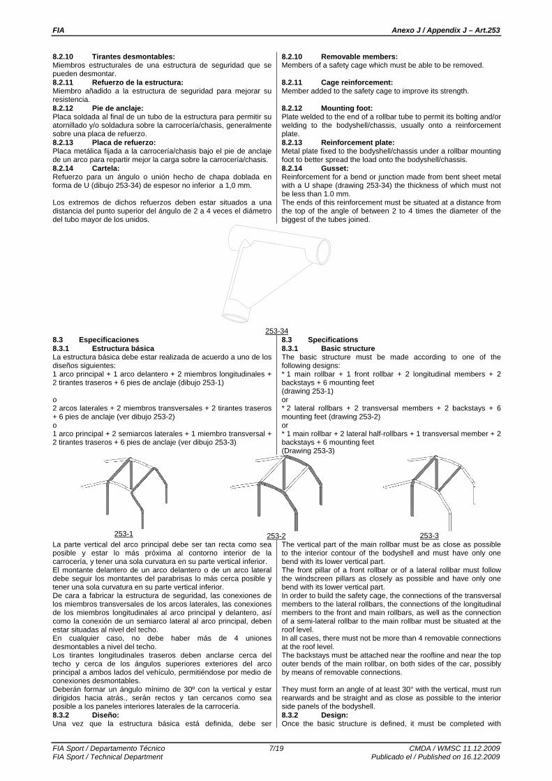
8.2.10 Tirantes desmontables: Miembros estructurales de una estructura de seguridad que se pueden desmontar. 8.2.11 Refuerzo de la estructura: Miembro añadido a la estructura de seguridad para mejorar su resistencia. 8.2.12 Pie de anclaje: Placa soldada al final de un tubo de la estructura para permitir su atornillado y/o soldadura sobre la carrocería/chasis, generalmente sobre una placa de refuerzo. 8.2.13 Placa de refuerzo: Placa metálica fijada a la carrocería/chasis bajo el pie de anclaje de un arco para repartir mejor la carga sobre la carrocería/chasis. 8.2.14 Cartela: Refuerzo para un ángulo o unión hecho de chapa doblada en forma de U (dibujo 253-34) de espesor no inferior a 1,0 mm. Los extremos de dichos refuerzos deben estar situados a una distancia del punto superior del ángulo de 2 a 4 veces el diámetro del tubo mayor de los unidos.
8.2.10 Removable members: Members of a safety cage which must be able to be removed. 8.2.11 Cage reinforcement: Member added to the safety cage to improve its strength. 8.2.12 Mounting foot: Plate welded to the end of a rollbar tube to permit its bolting and/or welding to the bodyshell/chassis, usually onto a reinforcement plate. 8.2.13 Reinforcement plate: Metal plate fixed to the bodyshell/chassis under a rollbar mounting foot to better spread the load onto the bodyshell/chassis. 8.2.14 Gusset: Reinforcement for a bend or junction made from bent sheet metal with a U shape (drawing 253-34) the thickness of which must not be less than 1.0 mm. The ends of this reinforcement must be situated at a distance from the top of the angle of between 2 to 4 times the diameter of the biggest of the tubes joined.
253-34
8.3 Especificaciones 8.3.1 Estructura básica La estructura básica debe estar realizada de acuerdo a uno de los diseños siguientes: 1 arco principal + 1 arco delantero + 2 miembros longitudinales + 2 tirantes traseros + 6 pies de anclaje (dibujo 253-1) o 2 arcos laterales + 2 miembros transversales + 2 tirantes traseros + 6 pies de anclaje (ver dibujo 253-2) o 1 arco principal + 2 semiarcos laterales + 1 miembro transversal + 2 tirantes traseros + 6 pies de anclaje (ver dibujo 253-3)
8.3 Specifications 8.3.1 Basic structure The basic structure must be made according to one of the following designs: * 1 main rollbar + 1 front rollbar + 2 longitudinal members + 2 backstays + 6 mounting feet (drawing 253-1) or * 2 lateral rollbars + 2 transversal members + 2 backstays + 6 mounting feet (drawing 253-2) or * 1 main rollbar + 2 lateral half-rollbars + 1 transversal member + 2 backstays + 6 mounting feet (Drawing 253-3)
253-1
253-2
253-3
La parte vertical del arco principal debe ser tan recta como sea posible y estar lo más próxima al contorno interior de la carrocería, y tener una sola curvatura en su parte vertical inferior. El montante delantero de un arco delantero o de un arco lateral debe seguir los montantes del parabrisas lo más cerca posible y tener una sola curvatura en su parte vertical inferior. De cara a fabricar la estructura de seguridad, las conexiones de los miembros transversales de los arcos laterales, las conexiones de los miembros longitudinales al arco principal y delantero, así como la conexión de un semiarco lateral al arco principal, deben estar situadas al nivel del techo. En cualquier caso, no debe haber más de 4 uniones desmontables a nivel del techo. Los tirantes longitudinales traseros deben anclarse cerca del techo y cerca de los ángulos superiores exteriores del arco principal a ambos lados del vehículo, permitiéndose por medio de conexiones desmontables. Deberán formar un ángulo mínimo de 30º con la vertical y estar dirigidos hacia atrás., serán rectos y tan cercanos como sea posible a los paneles interiores laterales de la carrocería. 8.3.2 Diseño: Una vez que la estructura básica está definida, debe ser
The vertical part of the main rollbar must be as close as possible to the interior contour of the bodyshell and must have only one bend with its lower vertical part. The front pillar of a front rollbar or of a lateral rollbar must follow the windscreen pillars as closely as possible and have only one bend with its lower vertical part. In order to build the safety cage, the connections of the transversal members to the lateral rollbars, the connections of the longitudinal members to the front and main rollbars, as well as the connection of a semi-lateral rollbar to the main rollbar must be situated at the roof level. In all cases, there must not be more than 4 removable connections at the roof level. The backstays must be attached near the roofline and near the top outer bends of the main rollbar, on both sides of the car, possibly by means of removable connections. They must form an angle of at least 30° with the vertical, must run rearwards and be straight and as close as possible to the interior side panels of the bodyshell. 8.3.2 Design: Once the basic structure is defined, it must be completed with

FIA Anexo J / Appendix J – Art.253
FIA Sport / Departamento Técnico 8/19 CMDA / WMSC 11.12.2009 FIA Sport / Technical Department Publicado el / Published on 16.12.2009
completada con miembros y refuerzos obligatorios (ver artículo 253-8.3.2.1), a los cuales se podrán añadir miembros y refuerzos opcionales (ver artículo 253-8.3.2.2). 8.3.2.1 Tirantes y refuerzos obligatorios: 8.3.2.1.1 Tirante diagonal: Vehículos homologados antes del 01/01/2002: La estructura debe incorporar uno de los tirantes diagonales definidos por los dibujos 253-4, 253-5 y 253-6. La orientación de la diagonal puede invertirse. En el caso del dibujo 253-6, la distancia entre los dos anclajes de la carrocería/chasis no debe ser superior a 300 mm
Los miembros deben ser rectos y pueden ser desmontables. El extremo superior de la diagonal debe unirse al arco principal a menos de 100 mm de la unión del arco principal con el tirante longitudinal trasero, o al tirante longitudinal trasero a menos de 100 mm de su unión con el arco principal (ver dibujo 253-52 para las medidas). El extremo inferior de la diagonal debe unirse al arco principal o a un tirante longitudinal trasero a menos de 100 mm del pie de anclaje (excepto para el caso del dibujo 253-6). Vehículos homologados desde el 01/01/2002: La estructura debe tener dos miembros diagonales en el arco principal de acuerdo al dibujo 253-7. Los miembros deben ser rectos y pueden ser desmontables. El extremo inferior de la diagonal debe unirse con el arco principal o con el tirante trasero a menos de 100mm del pie de anclaje (ver dibujo 253-52 para las medidas). El extremo superior de la diagonal debe unirse al arco principal a menos de 100mm de la unión de este con el tirante posterior.
compulsory members and reinforcements (see article 253-8.3.2.1), to which optional members and reinforcements may be added (see article 253-8.3.2.2). 8.3.2.1 Compulsory members and reinforcements: 8.3.2.1.1 Diagonal member: Cars homologated before 01.01.2002: The cage must have one of the diagonal members defined by Drawings 253-4, 253-5, 253-6. The orientation of the diagonal may be reversed. In the case of Drawing 253-6, the distance between the two mountings on the bodyshell/chassis must not be greater than 300mm. Members must be straight and may be removable. The upper end of the diagonal must join the main rollbar no further than 100 mm from its junction with the backstay, or the backstay no more than 100 mm from its junction with the main rollbar (see Drawing 253-52 for the measurement). The lower end of the diagonal must join the main rollbar or the backstay no further than 100 mm from the mounting foot (except for the case of Drawing 253-6). Cars homologated as from 01.01.2002: The cage must have two diagonal members on the main rollbar according to Drawing 253-7. Members must be straight and may be removable. The lower end of the diagonal must join the main rollbar no further than 100 mm from the mounting foot (see Drawing 253-52 for the measurement). The upper end of the diagonal must join the main rollbar no further than 100 mm from its junction with the backstay.
253-4
253-5
253-6
253-7
8.3.2.1.2 Tirantes de puertas: Se deberán montar uno o varios tirantes longitudinales a cada lado del vehículo de acuerdo a los dibujos 253-8, 253-9, 253-10 y 253-11 (dibujos 253-9, 253-10 y 253-11 para vehículos homologados a partir de 01-01-2007). Podrán ser desmontables. La protección lateral estará situada tan alta como sea posible pero sus puntos de anclaje superiores no estarán a más de la mitad de la altura total de la puerta medida desde su base. Si estos puntos de anclaje superiores están situados delante o detrás de la apertura de la puerta, esta limitación de altura es también válida para la intersección correspondiente al tirante y la apertura de la puerta. En el caso de una protección en “X” (dibujo 253-9), es aconsejable que los puntos de anclaje inferiores se fijen directamente sobre el larguero longitudinal de la carrocería (chasis) y que al menos una parte de la “X” sea una barra de una sola pieza. La conexión de los tirantes de puertas con el pilar de refuerzo del parabrisas (dibujo 253-15) está autorizada. Para competiciones sin copiloto, dichos miembros pueden ser montados sólo en el lado del conductor.
8.3.2.1.2 Doorbars: One or more longitudinal members must be fitted at each side of the vehicle according to Drawings 253-8, 253-9, 253-10 and 253-11 (Drawings 253-9, 253-10 and 253-11 for cars homologated as from 01.01.2007). They may be removable. The side protection must be as high as possible, but its upper attachment point must not be higher than half the height of the door opening measured from its base. If these upper attachment points are located in front of or behind the door opening, this height limitation is also valid for the corresponding intersection of the strut and the door opening. In the case of doorbars in the form of an "X" (Drawing 253-9), it is recommended that the lower attachment points of the cross-struts be fixed directly onto the longitudinal member of the bodyshell/chassis and that at least one part of the "X" be a single-piece bar. The connection of the doorbars to the windscreen pillar reinforcement (Drawing 253-15) is authorised. For competitions without co-driver, members may be fitted on the driver's side only.
253-8
253-9
253-10
253-11
8.3.2.1.3 Elementos de refuerzo de techo: Únicamente vehículos homologados desde el 01/01/2005: La parte superior de la estructura de seguridad debe cumplir con los dibujos 253-12, 253-13 y 253-14. Los refuerzos pueden seguir la curvatura del techo. Para competiciones sin copiloto, en el caso del dibujo 253-12 solamente, puede montarse un solo refuerzo pero su conexión
8.3.2.1.3 Roof reinforcement: Cars homologated as from 01.01.2005 only: The upper part of the safety cage must comply with one of Drawings 253-12, 253-13 and 253-14. The reinforcements may follow the curve of the roof. For competitions without co-drivers, in the case of Drawing 253-12 only, only one diagonal member may be fitted but its front

FIA Anexo J / Appendix J – Art.253
FIA Sport / Departamento Técnico 9/19 CMDA / WMSC 11.12.2009 FIA Sport / Technical Department Publicado el / Published on 16.12.2009
delantera debe estar situada del lado del piloto. Los extremos de los refuerzos deben estar a menos de 100mm de la unión entre arcos y miembros (esto no será de aplicación para la punta de la V formada por los refuerzos en los dibujos 253-13 y 253-14).
connection must be on the driver’s side. The ends of the reinforcements must be less than 100 mm from the junction between rollbars and members (not applicable to the top of the V formed by reinforcements in Drawings 253-13 and 253-14).
253-12
253-13
253-14 8.3.2.1.4 Pilar de refuerzo del parabrisas: Únicamente vehículos homologados desde el 01/01/2006: Deben estar montados a cada lado del arco delantero si la dimensión “A” es superior a 200mm (ver dibujo 253-15). Este refuerzo puede ser curvado a condición de que sea rectilíneo en vista lateral y que el ángulo de la curvatura no exceda 20º. Su extremo superior debe estar a menos de 100mm de la unión entre el arco delantero (lateral) y el miembro longitudinal (transversal) (ver dibujo 253-52 para las medidas). Su extremo inferior debe estar a menos de 100mm del pié de anclaje del arco (el pié de anclaje delantero en caso de arco lateral).
8.3.2.1.4 Windscreen pillar reinforcement: Cars homologated as from 01.01.2006 only: It must be fitted on each side of the front rollbar if dimension "A" is greater than 200 mm (Drawing 253-15). It may be bent on condition that it is straight in side view and that the angle of the bend does not exceed 20°. Its upper end must be less than 100 mm from the junction between the front (lateral) rollbar and the longitudinal (transversal) member (see Drawing 253-52 for the measurement). Its lower end must be less than 100 mm from the (front) mounting foot of front (lateral) rollbar.
253-15
8.3.2.1.5 Refuerzo de ángulos y uniones: Las uniones entre: - los miembros diagonales del arco principal, - los refuerzos del techo (configuración según dibujo 253-12 y sólo para vehículos homologados a partir de 01/01/2007), - los tirantes de las puertas (configuración del dibujo 253-9), - los tirantes de las puertas y los pilares de refuerzo del parabrisas (dibujo 253-15), deben estar reforzados por un mínimo de dos cartelas de acuerdo con el artículo 253-8.2.14. Si los tirantes de las puertas y el pilar de refuerzo del parabrisas no están situados en el mismo plano, el refuerzo debe estar fabricado en chapa de acero, siempre que cumpla con las dimensiones del art. 253-8.2.14. 8.3.2.2 Tirantes y refuerzos opcionales: Excepto otras indicaciones dadas en el artículo 253-8.3.2.1, los miembros y refuerzos mostrados en los dibujos 253-12 a 253-21 y 253-23 a 253-33, son opcionales y pueden ser instalados a voluntad del fabricante. Deben estar o bien soldados o bien instalados mediante conexiones desmontables. Todos los tirantes y refuerzos mencionados anteriormente pueden utilizarse por separado o combinados entre sí. 8.3.2.2.1 Refuerzo de techo (dibujos 253-12 a 253-14): Opcionales únicamente para los vehículos homologados antes del 01/01/2005. Para competiciones sin copiloto, en el caso del dibujo 253-12 solamente, puede montarse un solo refuerzo pero su conexión delantera debe estar situada del lado del piloto. 8.3.2.2.2 Pilar de refuerzo del parabrisas (dibujo 253-15): Opcional únicamente para los vehículos homologados antes del 01/01/2006. Este refuerzo puede ser curvado a condición de que sea rectilíneo en vista lateral y que el ángulo de la curvatura no exceda 20º. 8.3.2.2.3 Diagonales entre los tirantes traseros (dibujo 253-21): La configuración del dibujo 253-21 puede ser reemplazada por la del dibujo 253-22, en el caso de que se instale un refuerzo en el techo de acuerdo con el dibujo 253-14. 8.3.2.2.4 Refuerzos de anclaje sobre la suspensión
8.3.2.1.5 Reinforcement of bends and junctions: The junctions between: - the diagonal members of the main rollbar, - the roof reinforcements (configuration of Drawing 253-12 and only for cars homologated as from 01.01.2007), -the doorbars (configuration of Drawing 253-9), - the doorbars and the windscreen pillar reinforcement (Drawing 253-15), must be reinforced by a minimum of 2 gussets complying with article 253-8.2.14. If the doorbars and the windscreen pillar reinforcement are not situated in the same plane, the reinforcement may be made of fabricated sheet metal, provided it complies with dimensions in Article 253-8.2.14. 8.3.2.2 Optional members and reinforcements: Except other indications given in article 253-8.3.2.1, members and reinforcements shown in Drawings 253-12 to 253-21 and 253-23 to 253-33 are optional and may be installed as desired by the constructor. They must be either welded or installed by means of dismountable joints. All members and reinforcements mentioned above may be used separately or combined with one another. 8.3.2.2.1 Roof reinforcements (Drawings 253-12 to 253-14): Optional only for cars homologated before 01.01.2005. For competitions without co-drivers, in the case of Drawing 253-12 only, one diagonal member only may be fitted but its front connection must be on the driver’s side. 8.3.2.2.2 Windscreen pillar reinforcement (Drawing 253-15): Optional only for cars homologated before 01.01.2006. It may be bent on condition that it is straight in side view and that the angle of the bend does not exceed 20°. 8.3.2.2.3 Backstay diagonals (Drawing 253-21): The configuration of Drawing 253-21 may be replaced with that of Drawing 253-22 if a roof reinforcement complying with Drawing 253-14 is used. 8.3.2.2.4 Front suspension mounting points (Drawing 253-
A

FIA Anexo J / Appendix J – Art.253
FIA Sport / Departamento Técnico 10/19 CMDA / WMSC 11.12.2009 FIA Sport / Technical Department Publicado el / Published on 16.12.2009
delantera (dibujo 253-25): Los refuerzos deben estar conectados a los puntos de anclaje superiores de la suspensión. 8.3.2.2.5 Miembros transversales (dibujos 253-26 a 253-30): Los miembros transversales montados sobre el arco principal o entre los tirantes traseros pueden usarse para los anclajes de los arneses de seguridad, conforme al art. 253-6.2 (prohibida la utilización de conexiones desmontables). Para los miembros mostrados en los dibujos 253-26 a 253-27, el ángulo entre el brazo central y el vertical debe ser de al menos 30º. El miembro transversal fijado al arco delantero no debe invadir el espacio reservado para los ocupantes. Debe estar situado tan alto como sea posible, pero su borde inferior no debe estar situado por encima del punto más elevado del salpicadero. Para vehículos homologados a partir del 01/01/2007, no debe posicionarse por debajo de la columna de dirección. 8.3.2.2.6 Refuerzos de ángulo y unión (dibujos 253-31 a 253-34): Los refuerzos deben estar hechos de tubos o chapa curvada en forma de U cumpliendo con el art. 253-8.2.14. El espesor de los elementos que formen un refuerzo no debe ser menor de 1,0 mm. Los extremos de las barras de refuerzo no deben situarse a más distancia de la mitad de la longitud del miembro al que van unidos, a excepción de aquellos del arco delantero, que pueden unirse a las barras de refuerzo de las puertas y el arco delantero.
25): The extensions must be connected to the front suspension top mounting points. 8.3.2.2.5 Transversal members (Drawing 253-26 to 253-30): Transversal members fitted on the main rollbar or between the backstays may be used for the safety harness mountings in accordance with Article 253-6.2 (use of dismountable joints prohibited). For members shown on Drawings 253-26 and 253-27, the angle between the central leg and the vertical must be at least 30°. The transversal member fixed to the front rollbar must not encroach upon the space reserved for the occupants. It may be placed as high as possible but its lower edge must not be higher than the uppermost point of the dashboard. For cars homologated as from 01.01.2007, it must not be positioned below the steering column. 8.3.2.2.6 Reinforcement of bends or junctions (Drawings 253-31 to 253-34): Reinforcements must be made of tubes or bent-sheet metal with U shape complying with article 253-8.2.14. The thickness of the components forming a reinforcement must not be less than 1.0 mm. The ends of the tubular reinforcements must not be more than half way down or along the members to which they are attached, except for those of the junction of the front rollbar, which may join the junction of the door strut/front rollbar;
253-16
253-17
253-18
253-19
253-20
253-21
253-22
253-23
253-24
253-25
253-26
253-27
253-28
253-29
253-30

FIA Anexo J / Appendix J – Art.253
FIA Sport / Departamento Técnico 11/19 CMDA / WMSC 11.12.2009 FIA Sport / Technical Department Publicado el / Published on 16.12.2009
253-31
253-32
253-33
8.3.2.3 Configuración mínima de la estructura de seguridad: La configuración mínima de la estructura de seguridad se define como sigue:
Vehículos Homologados en
Con copiloto Sin copiloto
entre el 01.01.2002
y el 31.12.2004
Dibujo 253-35A Dibujo 253-36A
o simétrico
entre el 01.01.2005
y el 31.12.2005
Dibujo 253-35B Dibujo 253-36B
o simétrico
A partir del 01.01.2006
Dibujo 253-35C Dibujo 253-36C
o simétrico Las barras de las puertas y los refuerzos del techo pueden variar de acuerdo con los artículos 253-8.3.2.1.2 y 253-8.3.2.1.3.
8.3.2.3 Minimum configuration of the safety cage: The minimum configuration of a safety cage is defined as follows:
Cars homologated
With co-driver Without co-driver
between 01.01.2002
and 31.12.2004
Drawing 253-35A Drawing 253-36A
or symmetrical
between 01.01.2005
and 31.12.2005
Drawing 253-35B Drawing 253-36B
or symmetrical
as from 01.01.2006
Drawing 253-35C Drawing 253-36C
or symmetrical Doorbars and roof reinforcement may vary according to articles 253-8.3.2.1.2 and 253-8.3.2.1.3.
253-35A
253-35B
253-35C
253-36A
253-36B
253-36C
8.3.2.4 Tirantes desmontables: Si se usan tirantes desmontables en la construcción de una estructura de seguridad, las conexiones desmontables utilizadas deben estar conformes con un tipo aprobado por la FIA (ver dibujos 253-37 a 253-47). No podrán soldarse después de ensamblarse. Los tornillos y las tuercas deben ser de una calidad ISO 8.8 o superior (norma ISO). Las conexiones desmontables que cumplan con los dibujos 253-37, 253-40, 253-43, 253-46 y 253-47 están reservadas solamente para fijar los tirantes y los refuerzos opcionales descritos en el artículo 253-8.3.2.2 y están prohibidas para unir las partes superiores del arco principal, del arco delantero, de los semiarcos laterales y de los arcos laterales.
8.3.2.4 Removable members: Should removable members be used in the construction of a safety cage, the dismountable joints used must comply with a type approved by the FIA (Drawings 253-37 to 253-47). They must not be welded once assembled. The screws and bolts must have a minimum quality of 8.8 (ISO standard). Dismountable joints complying with Drawings 253-37, 253-40, 253-43, 253-46 and 253-47 are solely for attaching optional members and reinforcements described by article 253-8.3.2.2, and are forbidden for joining the upper parts of the main rollbar, of the front rollbar, of the lateral half-rollbars and of the lateral rollbars.
253-37 253-38 253-39

FIA Anexo J / Appendix J – Art.253
FIA Sport / Departamento Técnico 12/19 CMDA / WMSC 11.12.2009 FIA Sport / Technical Department Publicado el / Published on 16.12.2009
253-40 253-41 253-42
3636
40
253-43 253-44 253-45
26 m
ini
90
24.2534
3.23.0
2.5 mini
10
>= 10
>= 10
253-46 253-47 8.3.2.5 Especificaciones complementarias: Longitudinalmente, la estructura de seguridad debe estar completamente contenida entre los anclajes de los elementos de las suspensiones delanteras y traseras que soportan las cargas verticales (muelles y amortiguadores). Los refuerzos suplementarios que excedan estos límites se autorizan entre la estructura de seguridad y los puntos de anclaje de las barras antibalanceo traseras en la carrocería/chasis. Cada uno de esos puntos de anclaje puede ser conectado a la estructura de seguridad mediante un solo tubo de dimensiones de 30 x 1,5 mm. Para los vehículos homologados desde el 01/01/2002: En protección frontal, los refuerzos de los ángulos y de las uniones de los ángulos superiores del arco delantero deben ser visibles únicamente a través de la superficie del parabrisas descrita en el dibujo 253-48. Para todas las estructuras de seguridad de los vehículos de “Súper Producción” y “Súper 2000”, homologadas a partir del 01/01/2000, y para todas las estructuras de seguridad para vehículos de rallyes homologadas a partir de 01/01/2001: La apariencia de la estructura de seguridad en la abertura de la puerta debe cumplir con los criterios siguientes (ver dibujo 253-49): Dimensión A debe tener un mínimo de 300 mm. Dimensión B debe tener un máximo de 250 mm. Dimensión C debe tener un máximo de 300 mm. Dimensión E no debe ser superior a la mitad de la altura de la apertura de la puerta (H).
8.3.2.5 Additional constraints: Longitudinally, the safety cage must be entirely contained between the mounting points of the front and rear suspension elements carrying the vertical loads (springs and shock absorbers). Supplementary reinforcements exceeding these limits are authorised between the safety cage and the anchorage points of the rear anti-roll bars on the bodyshell/chassis. Each of these anchorage points may be connected to the safety cage by a single tube with dimensions of 30 x 1.5 mm. For cars homologated as from 01.01.2002: In frontal projection, reinforcements of bends and junctions of the upper corners of the front roll-cage must be only visible through the area of the windscreen described by Drawing 253-48. For all the safety cages for "Super Production" and "Super 2000" cars homologated as from 01.01.2000 and for all the safety cages for rally cars homologated as from 01.01.2001: The presence of the cage reinforcements in the door aperture must comply with the following criteria (Drawing 253-49) : - Dimension A must be a minimum of 300 mm - Dimension B must be a maximum of 250 mm - Dimension C must be a maximum of 300 mm - Dimension E must not be more than half the height of the door aperture (H).

FIA Anexo J / Appendix J – Art.253
FIA Sport / Departamento Técnico 13/19 CMDA / WMSC 11.12.2009 FIA Sport / Technical Department Publicado el / Published on 16.12.2009
253-48
253-49
8.3.2.6 Puntos de anclaje de la estructura a la carrocería o chasis: El mínimo de puntos de anclaje es: - 1 para cada montante del arco delantero; - 1 para cada montante de los arcos laterales o semiarcos laterales; - 1 para cada montante del arco principal; - 1 para cada tirante longitudinal trasero. Para conseguir un montaje óptimo sobre la carrocería, el guarnecido original puede ser modificado junto a la estructura de seguridad o sus puntos de anclaje, recortándolo o modificándolo localmente. Sin embargo, esta modificación no permite la eliminación completa de partes de la tapicería o guarnecido. Donde sea necesario, la caja de fusibles puede ser trasladada para fijar la estructura. Puntos de anclaje del arco delantero, arco principal, arcos laterales o semiarcos laterares: Cada punto de anclaje debe incluir una placa de refuerzo, de un espesor de, al menos, 3 mm. Cada pie de anclaje debe estar fijado por, al menos, 3 tornillos en una placa de refuerzo de, al menos, 3 mm de espesor y de, al menos, 120 cm2 que estará soldada a la carrocería. Para los vehículos homologados a partir del 01/01/2007, el área de 120 cm2 debe ser la de contacto entre la placa de refuerzo y la carrocería. Se muestran ejemplos en los dibujos 253-50 a 253-56. Para el dibujo 253-52 la placa de refuerzo no necesita estar soldada necesariamente a la carrocería. Los tornillos deben ser de, al menos, M8 de una calidad ISO 8.8 o mejor (norma ISO). Las tuercas serán autoblocantes o dotadas de arandelas de bloqueo. Recomendado a partir del 01/01/2009 y obligatorio a partir del 01/01/2010: El ángulo entre 2 tornillos (medido con respecto al eje central del tubo al nivel del pie de anclaje, véase el dibujo 253-50) no debe ser inferior a 60 grados. Puntos de anclaje de los tirantes traseros: Cada tirante longitudinal trasero deberá fijarse con un mínimo de 2 tornillos M8 con las placas de refuerzo de un área de, al menos, 60 cm2 (dibujo 253-57), o fijadas por un solo tornillo a doble cizalladura, (dibujo 253-58), bajo reserva de que sea de la sección y resistencia adecuadas y a condición de que se suelde un manguito al tirante. Estas exigencias son las mínimas. Como complemento podrán utilizarse fijaciones suplementarias, los pies de los arcos podrán soldarse a las placas de refuerzo, las estructuras (definidas por el art. 253-8.3.1) podrán soldarse a la carrocería/chasis. Caso especial: Para carrocerías/chasis que no sean de acero, cualquier soldadura entre la estructura de seguridad y la carrocería/chasis está prohibida, solo se permite el pegado de la placa de refuerzo a la carrocería/chasis.
8.3.2.6 Mounting of rollcages to the bodyshell/chassis: Minimum mounting points are: - 1 for each pillar of the front rollbar ; - 1 for each pillar of the lateral rollbars or lateral half-rollbars ; - 1 for each pillar of the main rollbar ; - 1 for each backstay. To achieve an efficient mounting to the bodyshell, the original interior trim may be modified around the safety cages and their mountings by cutting it away or by distorting it. However, this modification does not permit the removal of complete parts of upholstery or trim. Where necessary, the fuse box may be moved to enable a rollcage to be fitted. Mounting points of the front, main, lateral rollbars or lateral half-rollbars: Each mounting point must include a reinforcement plate at least 3 mm thick. Each mounting foot must be attached by at least three bolts on a steel reinforcement plate at least 3 mm thick and of at least 120 cm2 area which is welded to the bodyshell. For cars homologated as from 01.01.2007, the area of 120 cm2 must be the contact surface between the reinforcement plate and the bodyshell. Examples according to Drawings 253-50 to 253-56. For Drawing 253-52, the reinforcement plate need not necessarily be welded to the bodyshell. Fixing bolts must have a minimum diameter of M8 and a minimum quality of 8.8 (ISO standard). Fasteners must be self-locking or fitted with lock washers. Recommended as from 01.01.2009 and compulsory as from 01.01.2010: The angle between 2 bolts (measured from the tube axis at the level of the mounting foot cf. drawing 253-50) must not be less than 60 degrees. Mounting points of the backstays: Each backstay must be secured by a minimum of 2 M8 bolts with mounting feet of at least 60 cm2 area (Drawing 253-57), or secured by a single bolt in double shear (Drawing 253-58), provided it is of adequate section and strength and provided that a bush is welded into the backstay. These are minimum requirements. In addition, more fasteners may be used, the support plates of the mounting feet may be welded to reinforcement plates, the safety cage (as defined by article 253-8.3.1) may be welded to the bodyshell/chassis. Special case: For non steel bodyshells/chassis, any welding between the cage and the bodyshell/chassis is prohibited, only the bonding of the reinforcement plate on the bodyshell/chassis is permitted.
253-50 253-51 253-52

FIA Anexo J / Appendix J – Art.253
FIA Sport / Departamento Técnico 14/19 CMDA / WMSC 11.12.2009 FIA Sport / Technical Department Publicado el / Published on 16.12.2009
253-53 253-54 253-55
253-56 253-57 253-58
8.3.3 Especificaciones del material Sólo se autorizan tubos de sección circular. Especificaciones de los tubos utilizados:
Material Resistencia mínima a la
tracción
Dimensiones mínimas
(mm) Utilización
45 x 2.5 (1.75"x0.095")
o 50 x 2,0
(2.0"x0.083")
Arco principal o
arcos laterales, según la
construcción
Acero al carbono no
aleado (ver a continuación) conformado
en frío conteniendo un máximo del 0,3% de
carbono.
350 N/mm2
38 x 2.5 (1,5"x0.095")
o 40 x 2,0
(1,6"x0.083")
Semiarcos laterales y
otras partes de la estructura de
seguridad (a menos que se especifique
otra cosa en los artículos
anteriores) Nota: Para un acero no aleado, el contenido máximo de aditivos es de 1,7% para manganeso y de 0,6% para otros elementos. Al seleccionar el acero, debe prestarse atención a la obtención de buenas propiedades de elongación y adecuadas características de soldabilidad. El curvado del tubo debe hacerse en frío con un radio de curvatura (medido en el eje del tubo) de, al menos, 3 veces el diámetro. Si el tubo se ovaliza durante esta operación la relación entre el diámetro menor y mayor no será inferior a 0,9. La superficie al nivel de los ángulos debe ser uniforme sin ondulaciones ni fisuras. 8.3.4 Indicaciones para la soldadura: Deberán cubrir todo el perímetro del tubo. Todas las soldaduras deben ser de la mejor calidad posible y de una penetración total (preferentemente usando soldadura al arco en atmósfera de gas inerte). Aunque una buena apariencia exterior no garantiza necesariamente la calidad de la soldadura, una soldadura de mala apariencia no será nunca señal de un buen trabajo. En el caso de utilizar acero tratado térmicamente deben seguirse las instrucciones del fabricante (electrodos especiales, soldadura en atmósfera inerte). 8.3.5 Revestimiento protector: En los lugares donde los cuerpos de los ocupantes puedan entrar en contacto con la estructura de seguridad debe instalarse un revestimiento protector no inflamable. En aquellos puntos en los que los cascos de los ocupantes pudieran entrar en contacto con la estructura de seguridad, el
8.3.3 Material specifications Only tubes with a circular section are authorised. Specifications of the tubes used:
Material Minimum
tensile strength
Minimum dimensions
(mm) Use
45 x 2.5 (1.75"x0.095")
or 50 x 2.0
(2.0"x0.083")
Main rollbar or
Lateral rollbars according to construction
Cold drawn seamless unalloyed
carbon steel (see below) containing a maximum of
0.3 % of carbon
350 N/mm2
38 x 2.5 (1.5"x0.095")
or 40 x 2.0
(1.6"x0.083")
Lateral half-rollbars
and other parts
of the safety cage
(unless otherwise
indicated in the articles above)
Note: For an unalloyed steel, the maximum content of additives is 1.7 % for manganese and 0.6 % for other elements. In selecting the steel, attention must be paid to obtaining good elongation properties and adequate weldability. The tubing must be bent by a cold working process and the centreline bend radius must be at least 3 times the tube diameter. If the tubing is ovalised during bending, the ratio of minor to major diameter must be 0.9 or greater. The surface at the level of the bends must be smooth and even, without ripples or cracks. 8.3.4 Guidance on welding: These must be carried out along the whole perimeter of the tube. All welding must be of the highest possible quality with full penetration and preferably using a gas-shielded arc. Although good external appearance of a weld does not necessarily guarantee its quality, poor looking welds are never a sign of good workmanship. When using heat-treated steel the special instructions of the manufacturers must be followed (special electrodes, gas protected welding). 8.3.5 Protective padding: Where the occupants' bodies could come into contact with the safety cage, flame retardant padding must be provided for protection. Where the occupants' crash helmets could come into contact with the safety cage, the padding must comply with FIA standard 8857-

FIA Anexo J / Appendix J – Art.253
FIA Sport / Departamento Técnico 15/19 CMDA / WMSC 11.12.2009 FIA Sport / Technical Department Publicado el / Published on 16.12.2009
revestimiento debe cumplir con la Norma FIA 8857-2001, tipo A (ver la Lista Técnica nº 23 "Revestimiento de Arco de Seguridad Homologado por la FIA"). Aplicación: Para todas las categorías. ARTÍCULO 9: VISIÓN HACIA ATRÁS La visión hacia atrás debe estar asegurada por dos retrovisores exteriores (uno en el lado derecho y otro en el izquierdo). Esos retrovisores pueden ser los de serie. Cada retrovisor debe tener al menos una superficie de cristal de espejo de 90 cm2. El retrovisor interior es opcional. Aplicación: Grupos N, A, B, R y Súper 2000 Rallyes. Para Súper Producción véase el reglamento específico. Un recorte sobre el cuerpo del retrovisor (máximo 25 cm2 por retrovisor) se autoriza para ventilación del habitáculo. Aplicación: Sólo en rallyes, Grupos N, A, R y Súper 2000 Rallyes. ARTÍCULO 10: ANILLA PARA REMOLQUE Todos los vehículos deben estar equipados con una anilla de remolque delantera y otra trasera en todas las pruebas. Este enganche solo se usará si el vehículo puede moverse libremente. Deberá ser fácilmente visible y estar pintada en amarillo, rojo o naranja. ARTÍCULO 11: LUNAS Y REDES Lunas. Todas las lunas deben estar certificadas para su uso en carretera, dando fe su marcado. El parabrisas será de vidrio laminado. Se autoriza una banda parasol, a condición de que permita a los ocupantes ver las señales de tráfico (semáforos, señales...). El uso de láminas tintadas y/o láminas de seguridad se autoriza en las ventanas laterales y en la luna trasera. En ese caso, deben permitir a una persona situada a 5m del vehículo ver al conductor así como el contenido del vehículo. Sólo en rallyes: Si no se utilizan láminas plateadas o tintadas o si las ventanillas laterales o el techo solar no están hechos de cristal laminado es obligatorio el uso de láminas antidesintegración incoloras en las ventanillas laterales y en el techo solar. El espesor de dichas láminas no debe ser superior a 100 micras. El uso de láminas plateadas o tintadas se autoriza en las ventanas laterales, en la luna trasera y en el techo solar, bajo las siguientes condiciones: - Aperturas practicadas en estas láminas deben permitir a una persona situada en el exterior ver al conductor así como el contenido del vehículo. - Esta autorización debe mencionarse en el reglamento particular de la prueba. Aplicación: Grupo N, A y B. Para Super Producción ver el reglamento específico. Redes. Para pruebas de circuito, el uso de redes fijadas a la estructura de seguridad es obligatorio. Estas redes deben tener las siguientes características: - Anchura mínima de las bandas: 19 mm. - Tamaño mínimo de las aberturas: 25 x 25 mm - Tamaño máximo de las aberturas: 60 x 60 mm Y deben recubrir la abertura de la ventanilla hasta el centro del volante. ARTÍCULO 12: FIJACIONES DE SEGURIDAD DEL
PARABRISAS Estos elementos pueden usarse libremente. Aplicación: Grupos N, A y B. ARTÍCULO 13: CORTACORRIENTES El cortacorrientes general debe cortar todos los circuitos eléctricos (batería, alternador o dinamo, luces, claxon, encendido, controles eléctricos, etc.), y debe parar el motor.
2001, type A (see technical list n°23 "Roll Cage Padding Homologated by the FIA"). Application: For all categories. ARTICLE 9: REAR VIEW Rearward visibility must be ensured by two external rear-view mirrors (one on the right and one on the left). These rear-view mirrors may be as standard. Each rear-view mirror must have a reflecting surface of at least 90 cm2. An inside rear-view mirror is optional. Application: Groups N, A, B, R and Super 2000 Rallies. For Super Production see specific regulations. A cut-out (maximum surface 25 cm² per mirror) is authorised in the rear view mirror housing for cockpit ventilation. Application: only in rallies, Groups N, A, R and Super 2000 Rallies. ARTICLE 10: TOWING-EYE All cars will be equipped with a rear and front towing-eye for all events. This towing-eye will only be used if the car can move freely. It will be clearly visible and painted in yellow, red or orange. ARTICLE 11: WINDOWS / NETS Windows. The windows must be certified for road use, their marking standing as proof. The windshield must be made of laminated glass. A sun strip for the windscreen is authorised, on condition that it allows the occupants to see the road signs (traffic lights, traffic signs…). The use of tinted glass and/or safety film is permitted in side and rear windows. In such cases it must be possible for a person situated 5 m from the car to see the driver as well as the contents of the car. In rallies only: If silvered or tinted films are not used or if the side windows and the glass sunroof are not made from laminated glass, the use of transparent and colourless anti-shatter films on the side windows and the glass sunroof is mandatory. The thickness of these films must not be greater than 100microns. The use of silvered or tinted films is authorised, on the side and rear windows and on the glass sunroof, and on the following conditions: - Openings in these films must allow a person outside the car to see the driver as well as the contents of the car. - This authorisation must be mentioned in the supplementary regulations of the event. Application: Groups N, A, B. For Super Production see specific regulations. Nets. For events on circuits, the use of nets affixed to the safety roll-cage is mandatory. These nets must have the following characteristics: - Minimum width of the strips : 19 mm - Minimum size of the meshes : 25 x 25 mm. - Maximum size of the meshes : 60 x 60 mm. and must close up the window opening to the centre of the steering wheel. ARTICLE 12: SAFETY FIXING DEVICES FOR WINDSHIELD Such devices may be used freely. Application: Groups N, A, B. ARTICLE 13: GENERAL CIRCUIT BREAKER The general circuit breaker must cut all electrical circuits, battery, alternator or dynamo, lights, hooters, ignition, electrical controls, etc.) and must also stop the engine.

FIA Anexo J / Appendix J – Art.253
FIA Sport / Departamento Técnico 16/19 CMDA / WMSC 11.12.2009 FIA Sport / Technical Department Publicado el / Published on 16.12.2009
Para motores diesel que no tengan inyectores controlados electrónicamente, el cortacorrientes debe estar conectado a un dispositivo que interrumpa la admisión del motor. Debe ser un modelo antideflagrante y será accesible desde el interior y desde el exterior del vehículo. En el exterior, el sistema de accionamiento del cortacorrientes estará situado, obligatoriamente, en la parte inferior de uno de los montantes del parabrisas en los vehículos cerrados. Estará marcado por un rayo rojo en un triángulo azul con el borde blanco y una base de, al menos, 12 cm. Este accionamiento exterior solo afecta a vehículos cerrados. Aplicación: Instalación obligatoria para todos los vehículos que participen en pruebas de velocidad en circuito o montaña. Montaje recomendado para otras pruebas. ARTÍCULO 14: DEPÓSITOS DE SEGURIDAD APROBADOS
POR LA FIA En el caso de que un concursante utilice un depósito de combustible de seguridad, este deberá provenir de un fabricante aprobado por la FIA. Con el fin de obtener la aprobación de la FIA, un fabricante deberá haber probado la calidad constante de sus productos y su conformidad con las especificaciones aprobadas por la FIA. Los constructores de depósitos aprobados por la FIA, se comprometen a suministrar a sus clientes, exclusivamente, depósitos que cumplan con las normas aprobadas. Con este fin, sobre cada depósito suministrado deberá marcarse el nombre del fabricante, las especificaciones exactas según las cuales se ha fabricado este depósito, el número de homologación, la fecha de caducidad y el número de serie. El proceso de marcaje debe ser indeleble y debe ser aprobado con antelación por la FIA de acuerdo a la norma existente. 14.1 Especificaciones técnicas La FIA se reserva el derecho de aprobar cualquier otro conjunto de especificaciones técnicas tras estudiar el expediente proporcionado por los fabricantes interesados. 14.2 Especificaciones FT3 1999, FT3.5 ó FT5 Las especificaciones técnicas para estos depósitos están disponibles, bajo petición, en la Secretaría de la FIA. 14.3 Envejecimiento de los depósitos El envejecimiento de los depósitos flexibles implica una considerable reducción de sus propiedades físicas después de 5 años aproximadamente. No debe utilizarse ningún depósito más de 5 años después de su fecha de fabricación, excepto si es inspeccionado y revalidado por el fabricante durante un período de hasta otros dos años. Una ventana a prueba de fugas hecha en material no inflamable, instalada en la protección de los depósitos de seguridad de FT3 1999, FT3.5 o FT5, debe hacer posible la verificación de la fecha del final de validez. 14.4 Aplicación de estas especificaciones Los vehículos de Grupo N, Grupo A y Grupo B podrán estar equipados con un depósito de seguridad FT3 1999, FT3.5 ó FT5 si las modificaciones exigidas en el vehículo no sobrepasan aquellas permitidas por el reglamento. Se recomienda la utilización de espuma de seguridad en los depósitos FT3 1999, FT3.5 ó FT5. 14.5 Depósitos de combustible con cuellos de llenado, grupos A y N Todos los vehículos equipados con un depósito de combustible con un cuello de llenado que pase por el habitáculo, deben estar equipados con una válvula de no retorno homologada por la FIA. Esta válvula, del tipo de “una o dos compuertas”, debe instalarse en el cuello de llenado por el lado del depósito. El cuello de llenado, se define como el elemento usado para conducir el combustible desde el orificio de llenado del vehículo hasta el interior del depósito. ARTÍCULO 15: PROTECCIÓN CONTRA INCENDIOS Debe colocarse una mampara de protección eficaz entre el motor y los asientos de los ocupantes, con el fin de evitar el paso directo de las llamas en caso de incendio. Si esta pantalla estuviera constituida por los asientos traseros, es recomendable recubrirlos con un material ignífugo. ARTÍCULO 16: ASIENTOS, PUNTOS DE ANCLAJE Y
For Diesel engines having no electronically controlled injectors, the circuit breaker must be coupled with a device cutting off the intake into the engine. It must be a spark-proof model, and will be accessible from inside and outside the car. As for the outside, the triggering system of the circuit breaker will compulsorily be situated at the lower part of the windscreen mountings for closed cars. It will be marked by a red spark in a white-edged blue triangle with a base of at least 12 cm. This outside triggering system only concerns closed cars. Application: Compulsory fitting for all cars taking part in speed events on circuits or hill-climbs. The fitting is recommended for other events. ARTICLE 14: FIA APPROVED SAFETY FUEL TANKS Whenever a competitor uses a safety fuel tank, it must come from a manufacturer approved by the FIA. In order to obtain the FIA's agreement, a manufacturer must have proved the constant quality of its product and its compliance with the specifications approved by the FIA. Safety tank manufacturers recognised by the FIA must undertake to deliver to their customers exclusively tanks complying with the norms approved. To this end, on each tank delivered the name of the manufacturer, the exact specifications according to which this tank has been manufactured, the homologation date the date of the end of validity, and the series number, shall be marked. The marking process must be indelible and must have been approved beforehand by the FIA according to the prevailing standard. 14.1 Technical specifications The FIA reserves the right to approve any other set of technical specifications after study of the dossier submitted by the manufacturers concerned. 14.2 Specifications FT3 1999, FT3.5 or FT5 The technical specifications for these tanks are available, on request, from the FIA Secretariat. 14.3 Ageing of tanks The ageing of safety tanks entails a considerable reduction in the strength characteristics after approximately five years. No bladder shall be used more than 5 years after the date of manufacture, unless inspected and recertified by the manufacturer for a period of up to another two years. A leak-proof window made from non-flammable material, installed in the protection for FT3 1999, FT3.5 or FT5 tanks, must make it possible to check the date of the end of validity. 14.4 Applications of these specifications Group N, Group A and Group B cars may be equipped with an FT3 1999, FT3.5 or FT5 safety fuel tank if the modifications necessary do not exceed those allowed by the regulations. The use of safety foam in FT3 1999, FT3.5 or FT5 tanks is recommended. 14.5 Fuel tanks with filler necks, Groups A and N All cars fitted with a fuel tank with filler neck passing through the cockpit must be equipped with a non-return valve homologated by the FIA. This valve, of the type with one or two flaps, must be installed in the filler neck on the tank side. The filler neck is defined as being the means used to connect the fuel filler hole of the vehicle to the fuel tank itself. ARTICLE 15: PROTECTION AGAINST FIRE An efficient protective screen must be placed between the engine and the occupant's seat, in order to prevent the direct passage of flames in case of fire. Should this screen be formed by the rear seats, it is advisable to cover them with a flameproof coating. ARTICLE 16: SEATS, ANCHORAGE POINTS AND

FIA Anexo J / Appendix J – Art.253
FIA Sport / Departamento Técnico 17/19 CMDA / WMSC 11.12.2009 FIA Sport / Technical Department Publicado el / Published on 16.12.2009
SOPORTES Si se cambian las fijaciones o los soportes de origen, las nuevas piezas deben estar aprobadas por el fabricante del asiento para esa aplicación, o bien, cumplir con las siguientes especificaciones mencionadas a continuación: 1) Anclajes para fijación de soportes de asiento: El soporte de los asientos debe estar fijado: - Sobre los anclajes de los asientos utilizados en el vehículo de origen. - Sobre los anclajes homologados por el constructor en el kit de la Variante Opción ( en este caso los anclajes de origen podrán ser suprimidos) - Sobre los anclajes para la fijación de los asientos conforme al dibujo 253-65B. Los soportes de los asientos deben fijarse a los de fijación de los asientos por medio de 4 bulones mínimo por asiento de 8 mm de diámetro como mínimo.
SUPPORTS If the original seat attachments or supports are changed, the new parts must either be approved for that application by the seat manufacturer or must comply with the specifications mentioned below: 1) Anchorage points for fixing the seat supports: The seat supports must be fixed either: - on the anchorage points for fixing seats used on the original car - on the anchorage points for fixing seats homologated by the manufacturer as an Option Variant (in which case the original anchorage points may be removed) - on anchorage points for fixing seats in conformity with drawing 253-65B. The seat supports must be fixed to the anchorage points for fixing seats via at least 4 mounting points per seat, using bolts measuring at least 8mm in diameter.
253-65B
INSTRUCCIONES DE MONTAJE 1- Taladrar orificios (diámetro superior en el perímetro de las tuercas) en la base de la caja y la pared del túnel central. 2- Soldar las tuercas en las contraplacas y, a continuación, soldarlas a la base de la caja y la pared del túnel central. 3- Soldar los 2 insertos roscados en el travesaño y, a continuación, soldar las 2 pletinas en los extremos del mismo. 4- Fijar el conjunto mediante los 4 tornillos M8 clase 8.8 que se atornillarán en las tuercas soldadas.
FITTING INSTRUCTIONS 1- Drill holes (larger than nut outer diameter) in the bodyshell lower rail and in central tunnel wall. 2- Weld the nuts on the counterplates, then weld these on the bodyshell lower rail on the central tunnel wall. 3- Weld the 2 threaded inserts in the crossmember, then weld the endplates at each end of the crossmember. 4- Fix the assembly through 4 M8screws of 8.8 grade which will be screwed in the welded nuts.
2) Fijación de los soportes de asientos directamente sobre la carrocería/chasis Las fijaciones entre la carrocería/chasis deben estar compuestas como mínimo de 4 sujeciones por asiento usando tornillos de un diámetro mínimo de 8 mm y placas de refuerzo, de acuerdo al dibujo 253-65. El área de contacto mínima entre el soporte, chasis/carrocería y contraplaca es 40 cm2 por cada fijación.
2) Fixing of the seat supports directly onto the shell/chassis Supports must be attached to the shell/chassis via at least 4 mounting points per seat using bolts with a minimum diameter of 8 mm and counterplates, according to the drawing 253-65. The minimum area of contact between support, shell/chassis and counterplate is 40 cm2 for each mounting point.
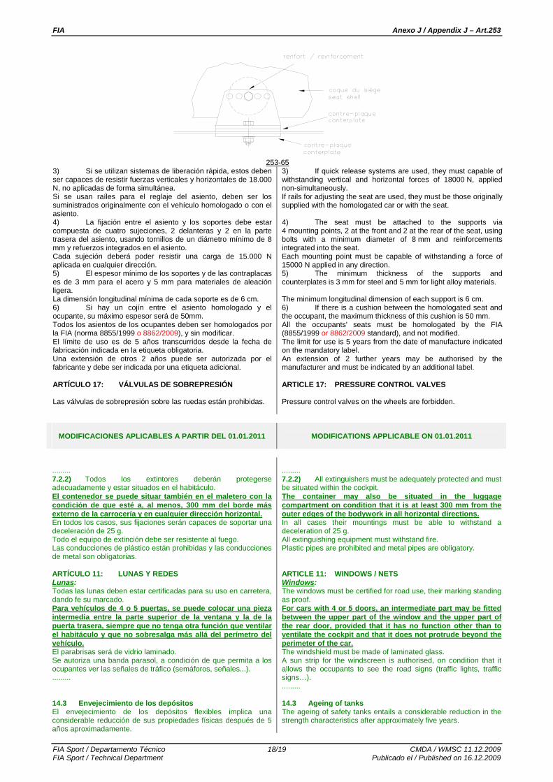
FIA Anexo J / Appendix J – Art.253
FIA Sport / Departamento Técnico 18/19 CMDA / WMSC 11.12.2009 FIA Sport / Technical Department Publicado el / Published on 16.12.2009
253-65
3) Si se utilizan sistemas de liberación rápida, estos deben ser capaces de resistir fuerzas verticales y horizontales de 18.000 N, no aplicadas de forma simultánea. Si se usan raíles para el reglaje del asiento, deben ser los suministrados originalmente con el vehículo homologado o con el asiento. 4) La fijación entre el asiento y los soportes debe estar compuesta de cuatro sujeciones, 2 delanteras y 2 en la parte trasera del asiento, usando tornillos de un diámetro mínimo de 8 mm y refuerzos integrados en el asiento. Cada sujeción deberá poder resistir una carga de 15.000 N aplicada en cualquier dirección. 5) El espesor mínimo de los soportes y de las contraplacas es de 3 mm para el acero y 5 mm para materiales de aleación ligera. La dimensión longitudinal mínima de cada soporte es de 6 cm. 6) Si hay un cojín entre el asiento homologado y el ocupante, su máximo espesor será de 50mm. Todos los asientos de los ocupantes deben ser homologados por la FIA (norma 8855/1999 o 8862/2009), y sin modificar. El límite de uso es de 5 años transcurridos desde la fecha de fabricación indicada en la etiqueta obligatoria. Una extensión de otros 2 años puede ser autorizada por el fabricante y debe ser indicada por una etiqueta adicional. ARTÍCULO 17: VÁLVULAS DE SOBREPRESIÓN Las válvulas de sobrepresión sobre las ruedas están prohibidas.
3) If quick release systems are used, they must capable of withstanding vertical and horizontal forces of 18000 N, applied non-simultaneously. If rails for adjusting the seat are used, they must be those originally supplied with the homologated car or with the seat. 4) The seat must be attached to the supports via 4 mounting points, 2 at the front and 2 at the rear of the seat, using bolts with a minimum diameter of 8 mm and reinforcements integrated into the seat. Each mounting point must be capable of withstanding a force of 15000 N applied in any direction. 5) The minimum thickness of the supports and counterplates is 3 mm for steel and 5 mm for light alloy materials. The minimum longitudinal dimension of each support is 6 cm. 6) If there is a cushion between the homologated seat and the occupant, the maximum thickness of this cushion is 50 mm. All the occupants' seats must be homologated by the FIA (8855/1999 or 8862/2009 standard), and not modified. The limit for use is 5 years from the date of manufacture indicated on the mandatory label. An extension of 2 further years may be authorised by the manufacturer and must be indicated by an additional label. ARTICLE 17: PRESSURE CONTROL VALVES Pressure control valves on the wheels are forbidden.
MODIFICACIONES APLICABLES A PARTIR DEL 01.01.2011
MODIFICATIONS APPLICABLE ON 01.01.2011
......... 7.2.2) Todos los extintores deberán protegerse adecuadamente y estar situados en el habitáculo. El contenedor se puede situar también en el maletero con la condición de que esté a, al menos, 300 mm del borde más externo de la carrocería y en cualquier dirección horizontal. En todos los casos, sus fijaciones serán capaces de soportar una deceleración de 25 g. Todo el equipo de extinción debe ser resistente al fuego. Las conducciones de plástico están prohibidas y las conducciones de metal son obligatorias. ARTÍCULO 11: LUNAS Y REDES Lunas: Todas las lunas deben estar certificadas para su uso en carretera, dando fe su marcado. Para vehículos de 4 o 5 puertas, se puede colocar una pieza intermedia entre la parte superior de la ventana y la de la puerta trasera, siempre que no tenga otra función que ventilar el habitáculo y que no sobresalga más allá del perímetro del vehículo. El parabrisas será de vidrio laminado. Se autoriza una banda parasol, a condición de que permita a los ocupantes ver las señales de tráfico (semáforos, señales...). ......... 14.3 Envejecimiento de los depósitos El envejecimiento de los depósitos flexibles implica una considerable reducción de sus propiedades físicas después de 5 años aproximadamente.
......... 7.2.2) All extinguishers must be adequately protected and must be situated within the cockpit. The container may also be situated in the luggage compartment on condition that it is at least 300 mm from the outer edges of the bodywork in all horizontal directions. In all cases their mountings must be able to withstand a deceleration of 25 g. All extinguishing equipment must withstand fire. Plastic pipes are prohibited and metal pipes are obligatory. ARTICLE 11: WINDOWS / NETS Windows: The windows must be certified for road use, their marking standing as proof. For cars with 4 or 5 doors, an intermediate part may be fitted between the upper part of the window and the upper part of the rear door, provided that it has no function other than to ventilate the cockpit and that it does not protrude beyond the perimeter of the car. The windshield must be made of laminated glass. A sun strip for the windscreen is authorised, on condition that it allows the occupants to see the road signs (traffic lights, traffic signs…). ......... 14.3 Ageing of tanks The ageing of safety tanks entails a considerable reduction in the strength characteristics after approximately five years.

FIA Anexo J / Appendix J – Art.253
FIA Sport / Departamento Técnico 19/19 CMDA / WMSC 11.12.2009 FIA Sport / Technical Department Publicado el / Published on 16.12.2009
No debe utilizarse ningún depósito más de 5 años después de su fecha de fabricación, excepto si es inspeccionado y revalidado por el fabricante durante un período de hasta otros dos años. Una ventana a prueba de fugas hecha en material no inflamable, instalada en la protección de los depósitos de seguridad de FT3 1999, FT3.5 o FT5, debe hacer posible la verificación de la fecha del final de validez. Se debe instalar en el protector de los depósitos de FT3 1999, FT3.5 o FT5, una carcasa a prueba de fugas, hecha de material no inflamable, fácilmente accesible y desmontable únicamente mediante el uso de herramientas, para permitir la verificación de la fecha de caducidad.
No bladder shall be used more than 5 years after the date of manufacture, unless inspected and recertified by the manufacturer for a period of up to another two years. A leak-proof window made from non-flammable material, installed in the protection for FT3 1999, FT3.5 or FT5 tanks, must make it possible to check the date of the end of validity. A leak-proof cover, made from non-flammable material, easily accessible and removable only with the use of tools, must be installed in the protection for FT3 1999, FT3.5 or FT5 tanks, in order to allow the checking of the validity expiry date.