Embed Size (px)
Citation preview

Background
The air flow around and through a building with several rooms belongs among the most difficult issues of the aerodynamic. Exemplary for the complexity of the influences are the interaction between adjacent buildings, the overlap of wind and thermal lift, as well as the simple effect of an open or closed inner door. In the specialist litera-ture but also in the relevant standards, such as EN 15242:2007, the physical models to calculate the determination of air flow rates in buildings are described in detail. For the practical application of these algorithms for example in the plan-ning of ventilation systems a description of mathematical approaches for itera-tive processes is missing. As suggested and commissioned by the European Ventilation Industry Association (EVIA) an Excel tool to calculate the air flow rates in buildings including infiltration on the basis of EN 15242 was made by the authors. This Excel tool is generally appli-cable even after reviewing this standard in the course of the EPBD mandate 480 (the future EN 16798-7 ”Energy perfor-
mance of buildings – Part 7: Ventilation for buildings – Module M5-1, M5-5, M5-6, M5-8 – Calculation methods for the determination of air flow rates in buildings including infiltration”).
Calculation methodThe calculation algorithm is based on a mesh model. So-called mesh networks occur in many technical areas, for example in gas and water supply networks. Each building plan can be converted into a meshed system. For the calculation of the airflows through a building the mesh method is a highly universal method also for viewing complex flow processes. The consideration of internal and external interference factors is possible. The aim of the method is to determine the air mass flows through the flow paths of a building. The building must be converted for the use of the method in a so-called airflow network that includes all flow paths, and their characteristics in terms of pressure losses and pres-sure profits, see Figure 1. This network consists essentially of loops (links) and nodes (rooms).
Calculation of building air infiltration and exfiltration with an Excel calculation tool
Thomas harTmannProf. Dr.-Ing.ITG Dresden Institute for Building Systems Engineering - Research and Application
ChrisTine KnausDipl.-Ing.ITG Dresden Institute for Building Systems Engineering - Research and Application
Florian eibisChB.Eng.ITG Dresden Institute for Building Systems Engineering - Research and Application Figure 1. Conversion of a building plan into a meshed system.
REHVA Journal – May 201516
Articles

Along a loop the mass flow remains constant. In flow direction there is a pressure drop caused by friction. Nodes are characterized by varying mass flows, but firm pressure conditions.
To solve this mesh network there exist a number of calculation methods. Together, all have the need to form meshes. A mesh in this case represents a closed flow path whose starting and ending points are identical.
The chosen mesh-based method needs a specified mass flow distribution at the beginning. This should lead to the fulfillment of all nodes conditions. During the solu-tion process, the respective mass flows are then constantly changed until the mesh-conditions are satisfied.
A very common and well-proven mesh-oriented solu-tion method is the Hardy-Cross method, which is often used in water and gas distribution networks. Due to its easy traceability and good data base, this method is implemented in the Excel tool.
There are basically two types of these methods: Sequential and simultaneous process. In the sequential method, each mesh is considered individually, taking into account the outcome of the consideration in the next mesh. An itera-tion step is complete when each mesh was calculated indi-vidually. In the simultaneous method always all meshes of the system are considered simultaneously. So a convergence is achieved faster. The disadvan-tage is the higher complexity of programming these processes and the traceability of interme-diate results is limited.
The Hardy-Cross method is an easy understandable iteration algorithm and calculable by hand. It is based on Newton’s approximation method (please see insert on the next page).
Structure of the toolThe handling of the tool has been made easier for the user by using a color-scale showing if all required input data are completely and in the right form (Figure 2).
In general, by clicking on the ”Save data” button all entered
data are saved and can be used for the calculation. The ”complete form” button changes into green showing that all data are in the correct form. Activating the ”Complete form” button closes the current input mask and the ”Overview” window or the next input mask appears.
With the Excel tool it is possible to calculate the air flow through the building with up to 20 rooms distributed over one or more floors, see Figure 3. The maximum of connections (e.g. windows, doors, air inlets) of one room is bounded to 20 connections. For each room a supply and/or exhaust air volume flow can be defined by a ventilation system. It has to be pointed out that the defined air volume flows are constant and independent of pressure conditions in the building minimizing the calculation effort. The calculation of the building air infiltration and exfiltration under steady-state conditions is performed with constant conditions defined by the user, see Figure 4.
Using the defined conditions following data can be determined / calculated:
• Aerodynamic pressure factor for each connection of the building (Cp-value)
• air tightness, which is split relatively (ratio of the area of the outer walls or fixed portion) to the respective external connection
• pressure difference for each opening
Figure 2. Information window – short description of the calculation tool.
REHVA Journal – May 2015 17
Articles

For this method, it is necessary to use a starting value x0 of unknown size. The closer this starting value to the actual solution x0 of the system
(equivalent to zero), the faster convergence is achieved. In the following recommendations the term convergence refers to situation when a predetermined error bound is reached. At each iteration step a correction increment is calculated, which is then subtracted from the initial value of the iteration. The calculation of the correction increment k occurs by solving equation (1).
( )( )
f xkf x
=′
(1)
f (x) the function value at the point x
f ́ (x) the function value of the first derivative at the point x
This procedure is used principally in the Hardy-Cross method. The variable x, which is modified during itera-tion, is equivalent to the mass flow along a loop. The function of which the root is determined describes the pressure balance along a closed loop system. Therefore it is necessary to know the fixed pressure differences (pressure sources), and the variable pressure differentials (flow resistance) and their functional relationship along a mesh. The pressure balance along an arbitrary loop m with o compounds can be calculated as follows:
0 = , ( , ) , ( ) (2)
Pressure balance around the loop m
, Differential pressure caused by wind between the starting and the ending point of a loop
( , ) Pressure due to thermal lift between the compounds i und i+1
, ( ) Pressure drop over the connection i, as a function of the current mass flow through this connection
o Number of connections of the loop m
The functional relationship of flow resistance of a connection as a function of the mass flow through
this connection may be arbitrary. The flow resistance depends normally on a coefficient and an exponent.
According to equation (2) the pressure balance is calcu-lated along each mesh. This must be differentiated according to the Hardy-Cross method with respect to the mass flow rate in order to calculate the correction mass flow .. For this purpose, it is only necessary to form the first derivative of single pressure losses of the flow resistance, since the pressure differences generated by pressure sources do not depend on the mass flow through the respective connections. The derivative of the pressure balance for a mesh m with o compounds can be determined in accordance with equation (3):
= , (3)
first derivative of the pressure balance along the mesh m
, sum of all the first derivatives of the pres-sure loss of the compounds of the mesh
Therefore, the pressure balance and its first derivate are determined along a loop. The resulting correction mass flow md can be calculated according to equation (4):
= (4)
pressure balance of the mesh m
first derivative of the pressure balance of the mesh m with respect to the mass flow
This correction mass flow is now subtracted from each mass flow, which is contained in the compound. The corrected mass flows are then used as starting values for the consideration of the next loop of the system. An iteration step is complete when all meshes were once considered. To check the accuracy of the resulting mass flows, the sum of the amounts of formed correc-tion mass flows of the iteration step is used. If the sum drops below a certain value, the iteration procedure can be aborted and the results are displayed in the corre-sponding form.
Explaining application Hardy-Cross method
REHVA Journal – May 201518
Articles

Summing up, the result of the tool are air flow rates for defined steady-state conditions in consideration of
wind pressure, thermal lift and – if there is one – the ventilation system.
2
4
living-room
kitchen
ground floorhall
13
5
67
1
2
3
12
bedroom
bathroom
upper floorhall4
5
6
10
11
8
9
14
13
15
0 m³/h 0 m³/h
supply air: 50 m³/h
exhaust air: 60 m³/h
exhaust air: 40 m³/h
supply air: 50 m³/h
Figure 3. Floor plan of a mid-terrace house (left: ground floor, right: upper floor) with supply and exhaust air flow rate of the rooms (boundary conditions: 6 rooms, 15 connections, 2 floors, balanced ventilation system, temperature ratio of 80%).
wind(wind direction, wind speed)
temperature(inside and outside)
ventilation systems(fan and system curve)
obstacles andshape of the building
vertical flow resistance characteristics of pressureloss (fan and system)
wind pressure pressure of thermal lift mechanically generatedpressure
building
internal distribution of flow resistance(doors, leakages, windows, air inlets)
internal distribution of pressure
distribution of volume flow rates
Figure 4. Factors influencing the air flow in building according to [Nowotny].
REHVA Journal – May 2015 19
Articles

Operation of the tool
In the input mask ”Overview” (Figure 5) under the heading project details and object details the user can provide several information. After choosing the calcu-lation unit: m³/h, m³/s or l/s further input fields are enabled.
Data of the building
The input mask ”General building information” is divided into three aspects:
• General building information• Information of the calculated flat• Ventilation system
In the aspect ”General building information” the user can provide details about:
• Number of rooms (up to 20 rooms possible)
• Building height in m• Width of the building (in wind direction) in m• Roof slope in °• Leakage characteristics (n [relative to indoor
volume], q [relative to outer envelope] or w [relative to floor area])
• Pressure difference of leakage characteristics in Pa• Value of air tightness in m³/(h·m²)• Exponent n (registered default value 0,67)In the aspect ”Information of the calculation flat” the input field, which is needed for the calculation, is high-lighted in yellow depending on the selected leakages characteristics. The three possible input fields are:
• Indoor volume in m³ (selecting n [relative to indoor volume])
• Outer envelope in m² (selecting q [relative to outer envelope])
• Floor area in m² (selecting w [relative to floor area])
Figure 5. Filled input mask ”Overview” for the example with enabled input fields.
REHVA Journal – May 201520
Articles

Information regarding the air-handling system can be given in the aspect ”Ventilation system”, see Figure 6.
Figure 7 shows the filled input mask ”General building information” for the mid-terrace house.
no yes
supply air ventilation exhaust air ventilation
free input
balanced ventilation
supply air temperature = outdoor temperature
value of supply air temperature in °C
calculation with temperature ratio
temperature ratio in %
Ventilation system existing?
Figure 6. Input data regarding the ventilation system.
Figure 7. Filled input mask “General building information” for the example after saving the entered data.
REHVA Journal – May 2015 21
Articles

Climate parameters
In the input mask ”Climate parameters” (Figure 8) information regarding the following values has to be completed:
• External (outdoor) temperature in °C• Reference wind speed (at reference height) in m/s• Reference height in m (registered default value 10 m)• Wind direction
Terrain information
Depending on the selection made in the input mask ”General terrain information” (Figure 9) different input fields have to be filled with information from the user:
• Terrain class (open terrain, country or urban/city)• Are there obstacles next to the building?
Figure 8. Filled input mask “General climate parameters” for the example after saving the entered data.
Figure 9. Filled input mask “General terrain information” for the example after saving the entered data.
REHVA Journal – May 201522
Articles

If there are obstacles next to the building, which are at least half of the height of the building further input fields are enabled:• Orientation of the obstacle(s) (north, east, south or west)• Height of the obstacles in m• Width of the obstacles in m• Distance between building and obstacles in m
Input building characteristics
Before the rooms are configured, it is possible to name the rooms for easy entry. If the possibility is not chosen, the rooms will retain their nomenclature like ”room 1”, ”room 2” etc. and the configuration of the individual rooms can start. If the possibility is chosen to name the rooms, another window will open where the individual nomenclature can be entered.
The data entered in this input mask ”General infor-mation of the room” refer to the selected room and following values:• Temperature in °C• Volume in m³• Height of the floor (relative to ground) in m
• Air flow caused by ventilation system? (depending to the selected ventilation system: supply air flow in m³/h, exhaust air flow in m³/h, or both air flows in m³/h)
• Number of connections (doors, windows etc.) (up to 20 connections per room possible)
Figure 10 shows exemplary the input mask ”General information of the room” for a supply air space.
In addition to the information about which room is selected and the global connection number further data are required in the input mask ”Connection data”, see Figure 11 next page. Depending on which connection and which type is chosen further information is neces-sary, for example• Connection: Orientation• Door (if closed): air tightness of the door• Wall: Outer area• Air inlet: Differential pressure
Rooms with only one connection like storerooms with a door and no window are not taken into account in
Figure 10. Filled input mask “General information of the room” for the living-room (supply air space) of the mid-terrace house.
REHVA Journal – May 2015 23
Articles

the calculation. Under steady-state conditions there is only very small air flow volume along the joints of the door due to the thermal lift between the lower and the upper joint of the door. Nevertheless, if these rooms should be taken into account in the calculation the door has to be split into two or more connections with different heights. The resulting air flow volumes are very small and there is a short-circuit flow around the door. The calculated air exchange rate does not represent the real local air exchange rate of the room.
Figure 12 shows exemplary the input mask ”Connection data” for connections from the ground floor hall to the living-room, the upper floor hall and outwards.
Activating the ”Calculate air flows” button the calculation starts and the results are shown in the worksheet ”Output”, see Table 1 and Table 2.
Changes of the input data / Calculation of variants
It is possible to calculate vari-ants by changing conditions like wind direction, air tightness of the building envelope, ventila-tion systems etc. in relevant input masks. All changes have to be saved and completed.
Changing the number of rooms (adding rooms or reducing the number of rooms) can be done in the input mask ”General building information” as long as there do not exist the first connection. After entering the first connection it is not possible to change the number of rooms in this project and a new project has to be started.Figure 11. Input data regarding the connections of a room.
m³
h · m
· Pa
n
othe
rroo
mco
nnectio
nou
twar
ds
with
win
dow
with
door
outs
ide
wal
l…
Conn
ectio
nto
?
open
pass
age
door
with
airt
rans
ferd
evic
edo
orro
ofw
ithw
indo
w,
door
orle
akag
eai
rinl
et
airi
nlet
curv
eda
tain
puto
fcha
ract
eristic
sw
ithle
akag
e
Clos
ed
-Airtig
htne
ssof
the
door
(ver
ytig
ht,ti
ght-
with
sill,
norm
al-w
ithou
tsill
orve
ryle
aky)
-Gap
leng
thli
nm
-Exp
onen
tn
-Gap
flow
coeffi
cien
tain
-Flo
wco
effici
entD
in
Ope
nN
ofu
rthe
rin
form
ation
isre
quir
ed.
-Ori
entatio
nof
the
conn
ectio
n(n
orth
,eas
t,so
uth
orw
est)
-Sou
rce
ofC p
-val
ues
(sta
ndar
dva
lues
orot
her
valu
es)
-Cp-
Valu
e-O
uter
area
ofth
ew
alli
nm
²-P
ortio
nof
the
airtig
htne
ssfr
omth
ebu
ildin
g(r
elati
veto
outd
oorw
alla
rea
orfix
edpo
rtion
)-P
ortio
nin
%
-Diff
eren
cepr
essu
rein
Pa-A
irflo
wq v
inm
³/h-E
xpon
entn
-Flo
wco
effici
entD
in
-Exp
onen
tn-F
low
coeffi
cien
tDin
m³
h · P
an
m³
h · P
an
m³
h · P
an
REHVA Journal – May 201524
Articles
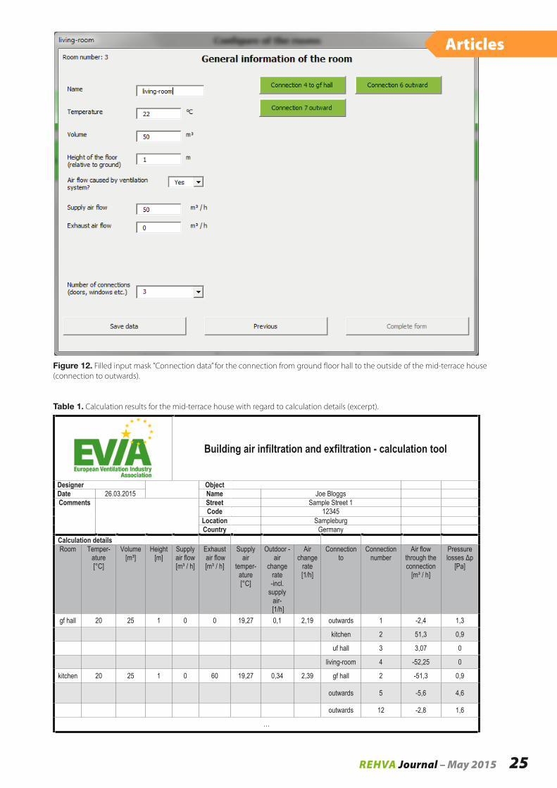
Figure 12. Filled input mask ”Connection data” for the connection from ground floor hall to the outside of the mid-terrace house (connection to outwards).
Building air infiltration and exfiltration - calculation tool
Designer ObjectDate 26.03.2015 Name Joe BloggsComments Street Sample Street 1
Code 12345Location SampleburgCountry Germany
Calculation detailsRoom Temper-
ature[°C]
Volume[m³]
Height[m]
Supply air flow [m³ / h]
Exhaustair flow [m³ / h]
Supplyair
temper- ature[°C]
Outdoor -air
changerate -incl.
supply air- [1/h]
Air change
rate[1/h]
Connection to
Connectionnumber
Air flow through the connection
[m³ / h]
Pressure
[Pa]
gf hall 20 25 1 0 0 19,27 0,1 2,19 outwards 1 -2,4 1,3
kitchen 2 51,3 0,9
uf hall 3 3,07 0
living-room 4 -52,25 0
kitchen 20 25 1 0 60 19,27 0,34 2,39 gf hall 2 -51,3 0,9
outwards 5 -5,6 4,6
outwards 12 -2,8 1,6
…
Table 1. Calculation results for the mid-terrace house with regard to calculation details (excerpt).
REHVA Journal – May 2015 25
Articles

Changes of the connection of rooms like orientation, type or increase the number of connections can be done without problems in the relevant windows ”General information of the room”. However to reduce the number of the connection, a new project has to be started or a saved version has to be used.
SummaryOn behalf of the European Ventilation Industry Association (EVIA) an Excel tool was developed to for example use the in EN 15242 described physical models to calculate air flow rates in buildings for daily work of building and system planers. This provides users with a convenient facility to determine air flow rates room by room caused by leakages and externally mounted air transfer devices under variation of essential boundary conditions and under steady-state condi-tions. The Excel calculation tool can be obtained free of charge and together with a detailed manual in the
EVIA download area (http://www.evia.eu/en/Media-Centre/Download/) of the EVIA homepage (English or German version).
Literature
EN 15242:2007 Ventilation for buildings – Calculation methods for the determination of air flow rates in buildings including infiltration.
prEN 16798-7:2015 Energy performance of buildings – Part 7: Ventilation for buildings – Module M5-1, M5-5, M5-6, M5-8 - Calculation methods for the determina-tion of air flow rates in buildings including infiltration.
Nowotny, S. & Feustel, H.E. 1996. Lüftungs- und klima-technische Gebäudeausrüstung – Grundlagen und Berechnungsmodelle, Wiesbaden; Berlin: Bauverlag. Ventilation and air conditioning building services – Basics and calculation models.
connection dataStart End Number Type Orientation Cp-
value[-]
Wall area [m²]
Portion of building leakage
[%]
Height (absolut) [m]
Flow coefficient [m³/(s*Pan)
Exponent n[-]
gf hall outwards 1 Outside wall with door East -0,7 5 7,14 2 - 0,67
Kitchen gf hall 2 Door - - - - 2 1,50E-02 0,67
uf hall gf hall 3 Open passage - - - - 3,625 2,78E+02 0,67
…
Table 2. Calculation results for the mid-terrace house with regard to connection data (excerpt).
REHVA Journal – May 201526
Articles
World Sustainable Energy Days 2016Deadline
Call for Papers 9 October 2015
World Sustainable Energy Days24 – 26 February 2016, WELS / AUSTRIA
WWW.WSED.AT
2016
OÖ Energiesparverband, Landstraße 45, A-4020 Linz,
ZVR 171568947