Embed Size (px)
Citation preview
USAAEFA PROJECT NO. 76-09-2A/
ARTIFICIAL ICING TEST
UTILITY TACTICAL TRANSPORTAIRCRAFT SYSTEM (UTTAS)
BOEING VERTOL YUH-61A HELICOPTER
FINAL REPORT
JOHN F. HAGENMAJ, FA
US ARMY JAMES C. O'CONNORPROJECT OFFICER/PILOT CPT, CE
US ARMYEDWARD J. TAVARES PROJECT PILOT
CPT, TCUS ARMY
PROJECT ENGINEER
JANUARY 1977 DTIC
DISTRIBUTION STATEMENT A. JAN 11 E82
Appmved Jot publia releaejelDist-ibution Unlimited D
UNITED STATES ARMY AVIATION ENGINEERING FLIGHT ACTIVITYEDWARDS AIR FORCE BASE, CALIFORNIA 93523
81 11 30 144
I.V.1
DISCLAIMER NOTICE
The findings of this report are not to be construed as an official Department ofthe Army position unless so designated by other authorized documents.
DISPOSITION INSTRUCTIONS
)estroy this report when it is no longer needed. Do not return it to the originator.
TRADE NAMES
The use of trade names in this report does not constitute an official endorsementor approval of the use of the commercial hardware and software.
L IL
UNCLASSIFIEDSECURITY CLASSIFICATION OF: THIS PAGE ("Oen flea. nt
REPORT DOCUMENTATION PAGE BEOECMLEIGFRIREPORT NUMBER 2. GOVT ACCESSION NO. 3 RECIPIENT'S CATALOG NUMBER
USAAEFA PROJECT NO. 76-409-2 -h~ 1/ 47,514. TITLE (and Subtitle) S. TYPE OF REPORT 6 PERIOD COVERED
ARTIFICIAL ICING TEST FINAL REPORTUTILITY TACTICAL TRANSPORT AIRCRAFT 9 October - 3 November 1976
SYSTEM (UTTAS) 6. PERFORMING ORG. REPORT NUM11101BOEING VERTOL YUH-61A HELICOPTER USAAEFA PROJECT NO. 76-09-1
7 AIJTHOR(a) S. CONTRACT OR GRANT NUMBER(.)
MAJ JOHN F. HAGENCPT EDWARD J. TAVARESCPT JAMES C. O'CONNOR
9 PERFORMING ORGANIZATION NAME AND ADDRESS 10. PROGRAM ELEMENT PROJECT. TASKAREA . WORK UN IT 'NUMBERS
US ARMY AVIATION ENGINEERING FLIGHT ACTIVITY 68-U-UA-029-0I-68-ECEDWARDS AIR FORCE BASE, CALIFORNIA 93523
1. CONTROLLING OFFICE NAME AND ADDRESS 12. REPORT DATE
US ARMY AVIATION ENGINEERING FLIGHT ACTIVITY JANUARY 1977EDWARDS AIR FORCE BASE, CALIFORNIA 93523 13. NUMBER OF PAGES
____ ___ ____ ___ ___ ____ ___ ____ ___ ___ ____ ___ ___94
4 MONITORING AGENCY NAME A ADDRESSIf different from Controlling Office) 15. SECUIRITY CLASS. (of this *eport)
UNCLASSIFIED15a. DECL ASSI FICATON/ DOWNGRADING
SCHEDULE
16. DISTRIBUTION STATEMENT (of this Report) I DISkUBUTION STATEMENT AApProved fox Public release;
Disltribution Unlimited
17. DISTRIBUTION STATEMENT (of the obettedt entered in Block 20, if differet fromt ReporI .
IS SUPPLEMENTARY NOTES ,
19 KEY WORDS (Continue on reseroc aide if neesr mnd Idewily by block number)
Artificial icing evaluation Anti-ice systems for enghes, engine air induction.Boeing Vertol YUII-61 A helicopter systems, pitot tubes, and windshieldsModerate icing conditions Electrothermal rotor blade protectionDeice system functioning and
not functioning20 ABSTRACT (Continue onr,06 tiere de if neeemeary and IdentIify hy block number)
The United States Army Aviation Engineering Flight Activity conducted an in-flightartificial icing evaluation of the Be--oIm -N-1~o YUH-61IA helicopter equipped witha prototype deice system. This evaluation was conducted from 9 October through
3November 1976 at Fort ~Winwright7Afiiski'During the test program 3.2 hourswere flown in the artificial icing environment. Of this time, 2.8 hours were flownwith the deice system functioning, and 0.4 hour was flown with the system not
(contd)
DD I JrAN71 1473 EDITION OF INOV GS 1SOUSOLETE UNCLASSIFIED. ~ ~riei.~~( a y SIECURITY CLASSIFICATION OF THIS PACE (When Dot ered
MEN
UNCLASSIFIEDScCuAIT , CLASSIFICATION OF THIS PAGE(Whe Doe oE4ered)
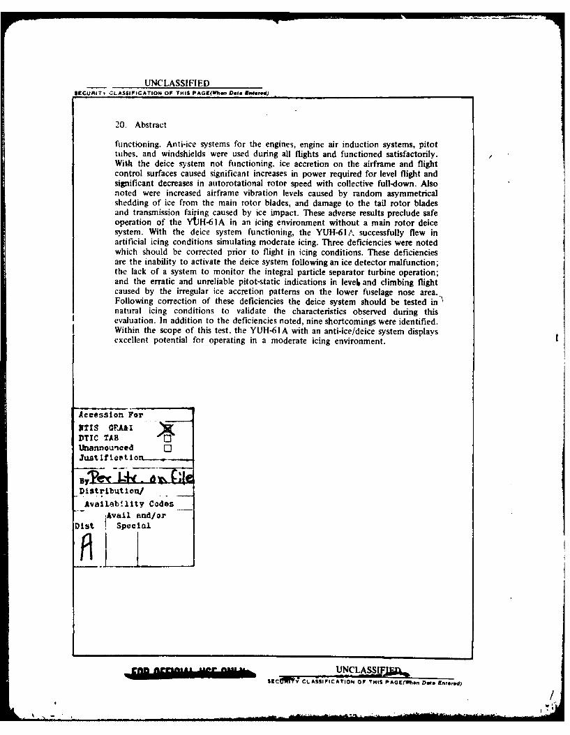
20. Abstract
functioning. Anti-ice systems for the engines, engine air induction systems, pitottubes, and windshields were used during all flights and functioned satisfactorily.With the deice system not functioning, ice accretion on the airframe and flightcontrol surfaces caused significant increases in power required for level flight andsignificant decreases in autorotational rotor speed with collective full-down. Alsonoted were increased airframe vibration levels caused by random asymmetricalshedding of ice from the main rotor blades, and damage to the tail rotor bladesand transmission fairing caused by ice impact. These adverse results preclude safeoperation of the YJH-6 IA in an icing environment without a main rotor deicesystem. With the deice system functioning, the YUH-61A successfully flew inartificial icing conditions simulating moderate icing. Three deficiencies were notedwhich should be corrected prior to flight in icing conditions. These deficienciesare the inability to activate the deice system following an ice detector malfunction;the lack of a system to monitor the integral particle separator turbine operation;and the erratic and unreliable pitot-static indications in level and climbing flightcaused by the irregular ice accretion patterns on the lower fuselage nose area.Following correction of these deficiencies the deice system should be tested in Nnatural icing conditions to validate the characteristics observed during thisevaluation. In addition to the deficiencies noted, nine shortcomings were identified.Within the scope of this test, the YUH-61A with an anti-ice/deice system displaysexcellent potential for operating in a moderate icing environment.
Accession For
NTIS GQPA&IDTIC TAB'nannounced 0
Juat ifiet ion .
Distributiton/
Avallebility CodesAvail and/or
Dist Special
cENn _ CLASSiSEC TYVCLASSIFICATION, OF THIS PAGE(hsn Date Entered)
/.
DEPARTMENT OF THE ARMYHO, US ARMY AVIATION RESEARCH AND DEVELOPMENT COMMAND
P 0 BOX 209. ST. LOUIS, MO 63166
DRDAV-EQ MAR 7 1978
SUBJECT: USAAEFA Project No. 76-09-2, Artificial Icing Test, UtilityTactical Transport Aircraft System (UTTAS), Boeing VertolYUH-61A Helicopter, January 1977
SEE DISTRIBUTION
1. The Directorate for Development and Engineering position on USAAEFA'sConclusions and Recommendations are provided herein. Since the UH-61Awas not selected for production to meet U.S. Army UTTAS requirements, noaction has been taken on this report, however, intended action based onnegotiations of the UTTAS Source Selection Evaluation Board (SSEB), hadit been selected, are briefly noted. Paragraph numbers from the subjectreport are provided for reference.
a. Paragraph 62: The test results are clear regarding unsatisfactoryoperations in moderate icing conditions with the blade deicing systeminoperative, however, in the event of failure of the rotor deice systemin flight, safe continued operation in trace or light ice may well bepossible.
b. Paragraph 65a: Design change to permit the deicing system tooperate even after an ice detector malfunction would be included in anyfuture U11-61 procurement efforts.
c. Paragraph 65b:
(1) This paragraph identifies the lack of a system to monitor IPSturbine operation as a deficiency based on:
(a) The engine's susceptibility to FOD without an operable blower.
(b) The requirement to terminate flight in icing conditions if blowerwas inoperative.
(2) The following points outline our position on why this is not adeficiency:
(a) The requirement for termination of flight if an inoperative blower
was indicated was specifically a conservative test requirement and is not
considered valid for production considerations.
% . ./
DRDAV-EQ MAR 7 1978
SUBJECT: USAAEFA Project No. 76-09-2, Artificial Icing Test, UtilityTactical Transport Aircraft System (UTTAS), Boeing VertolYUH-61A Helicopter, January 1977
(b) No instances of a failed blower of the production configurationhas occurred; however, even so, an anti-icing test point was successfullydemonstrated with the blower inoperative.
(c) No value of FOD effectiveness with or without a failed blower isknown; however, experience with ice ingestion indicated no sizable piece
could get through the swirl vanes, past the splitter lip, through the deswirl
vanes and IGV without being broken up.
(d) Instances of FOD encountered thus far, blower operative, did notdisable an engine beyond some reduced power. The conclusion noted in paragraph65.b will be part of a continuing evaluation, but is not considered imperativeuntil conditions warrant it.
(e) Production maintenance inspections procedures are being establishedwhich will include at least a borescope port on the blower.
d. Paragraph 65c: Correction would be incorporated for future utilizationof the UH-61.
e. Paragraph 66a thru d and f thru i: Correction to these shortcomingswere negotiated by the UTTAS SSEB to be included in UH-61 productionspecifications.
f. Paragraph 66e: We do not agree that this is a shortcoming. Centerwindshield ice protection was deliberately deleted because no adverse impactfrom its non-existence on the CH-47 and S-61 helicopters. The increasedvisibility, if ice protection were present, is insignificant in relation toits cost, due to the large offset angle of each crewmember.
g Paragraphs 69 thru 72 and 74 thru 77: Concur with these recommendations,action would be taken if future utilization of the UH-61 is required.
h. Paragraph 73: This WARNING has a significant drawback since thepurpose of the helicopter is troop assault in which rapid unloading is essential,therefore, it would be applied to peacetime operation only as a CAUTION.
2. This report is another documented example of how essential rotor systemdeicing systems are for adequate airworthiness when operation in moderate ice
is required.
FOR THE COMMANDER:
ALTER A. RATCLIFFColonel, GSDirector of Developmentand Engineering
2
PREFACE
The artificial icing test of the YUH-61A helicopter was conducted jointly by theUnited States Army Aviation Engineering Flight Activity (USAAEFA) and BoeingVertol Company at Fort Wainwright, Alaska. The test aircraft was maintained byUSAAEFA with backup support provided by Boeing Vertol. Aircraft testinstrumentation was supplied, installed, and maintained by Boeing Vertol personnel.
Special acknowledgment is made for the outstanding assistance and supportprovided at Fort Wainwright by MAJ James C. Hoodenpyle, CW2 Jefferson R.Watts, and the officers and men of the 222d Aviation Battalion.
Descriptive material on the Normalair-Garrett ice detector system presented inappendix D is used with permission of the company.
V.'
TABLE OF CONTENTS
Page
INTRODUCTION
Background ........... ........................ 3Test Objectives ........... ...................... 3Description ............ ........................ 4Test Scope ............ ........................ 4Test Methodology ......... ...................... 6
RESULTS AND DISCUSSION
General 7.........................7Deice System Operation .... .................. .7Anti-ice and Heating Systems Operation ..... ............ 9
General ........... ....................... 9Engine Anti-ice .......... .................... 9Engine Air Induction Anti-Ice .................... 10
Engine Inlet (D-ring) Fairing .... ............. .. 10Engine Transmission Fairing .... ............. .. 10
Windshield Anti-Ice ....... .................. .10Pitot-Static Anti-Ice ....... .................. .11Cabin Heater .......... ..................... 12
Integral Particle Separator ....... .................. .. 12Flight Control Surface Ice Accretion and
Shedding Characteristics ....... ............... 12General .... ....................... 12Unheated Blade Phase ...... ................. .. 13Heated Blade Phase ....... ................... 15
Airframe Ice Accretion and Shedding Characteristics ... ....... 17Level Flight Performance ....... .................. .20Autorotational Performance ....... ................. .22Handling Qualities ........ ..................... .22Vibration Characteristics ....... .................. .24Human Factors .......... ...................... 24Ice Detectors ......... ....................... .25
General .... ....................... 25Rosemount Ice Detector ...... ................ .25Normalair-Garrett Ice Detector ...... .............. 26
1
CONCLUSIONS
General. ............ ............. 27
Deficiencies and Shortcomings . . . .. .. .. .. .. . .28
RECOMMENDATIONS. .... ................. 30
APPENDIXES
A. References. ...... ................. 31B. Deice/Anti-Ice Systems Description .. .............. 33C. Helicopter Icing Spray System Description. .. ......... 46D. Instrumentation and Special Equipment .. ........... 48E. Test Techniques and Data Analysis Methods .. ......... 61F. Icing Flight Summaries. .. ...... ........ ... 72G. Test Data .. ........................ 82H. Photographs .... .................... 85
DISTRIBUTION
2

INTRODUCTION
BACKGROUND
1. The United States Army requires an improved operational capability in itsutility transport aircraft to satisfy the demand for increased performance andsurvivability in the mid-intensity combat environment. The utility tactical transportaircraft system (UTTAS) is being developed in response to this requirement andwill replace the current utility helicopter in the Army inventory. On 30 August1972 the United States Army Aviation Systems Command (AVSCOM)* awardeda contract to the Boeing Vertol Company to produce three prototype aircraft andone ground test vehicle. The United States Army Aviation Engineering FlightActivity (USAAEFA) completed an Army Preliminary Evaluation of the BoeingYUH-61A in March 1976. A Government Competitive Test (GCT) was completedin September 1976.
2. The UTTAS shall be capable of operation under climatL conditions up toand including moderate icing (ref 1, app A). As a result, USAAEFA was taskedby an AVSCOM test directive (ref 2) to conduct artificial icing tests of theYUH-61A in accordance with the approved test plan (ref 3).
TEST OBJECTIVES
3. The overall objectives of the UTTAS artificial icing tests were as follows:
a. To provide data to be used for evaluating the ability of the helicopterto effectively operate in a moderate icing environment.
b. To detect, and allow for early correction of, any aircraft deficienciesor shortcomings.
4. Specific objectives of each testing phase are listed below.
a. Unheated blade phase:
(1) Evaluate the effectiveness of the windshield, pitot-static, engine airinduction, and engine anti-ice systems.
(2) Determine the need for additional anti-ice/deice systems.
b. Heated blade phase:
(1) Determine the otential effectiveness of the contractor-provided prototypeanti-ice/deice systems.
*Since redesignated the Army Aviation Research and Development ('ommand(AVRADCOM). 3
FOR OFFICIAL USE ONLY
, /
(2) Provide the UTTAS competitors a limited opportunity to further developanti-ice/deice systems.
DESCRIPTION
5. The UTTAS is a twin-turbine, single-main-rotor helicopter designed fortransporting cargo, II combat troops. and weapons during visual or instrumentmeteorological conditions (VMC or IMC). Nonretractable wheel-type landing gearare provided. The main and tail rotors are both four-bladed. with a capability ofmanual main rotor blade and tail pylon folding. A movable horizontal stabilizeris located on the tail rotor pylon. A more detailed description of the YUH-61A(SN 73-21658) is contained in the prime item development specification (PIDS).operator's manual, and the GCT final report (refs 4, 5. and 6, app A). Theprototype deice system installed on the YUH-61A is designed to provide thecapability to deice the main rotor blades, tail rotor blades, and horizontal stabilizer.The system incorporates electrothermal heating elements installed on the leadingedges of the main and tail rotor blades and the horizontal stabilizer. The heatingelements on the main and tail rotor blades are an integral component of the standardmanufactured blades and were not a kit component installed specifically for theicing test. With the exception of one main rotor blade, the blades had been installedand flown on test aircraft prior to the icing tests. When the deice system is turnedon, its operation is controlled by a deice controller unit based on signals receivedfrom an ice detector and outside air temperature (OAT) sensor. System ON timeis varied as a function of OAT and system OFF time is varied as a function oficing rate. The YIJH-61A also has anti-ice provisions for the pilot and copilotwindshields. pitot tube, engine, engine inlet fairing, and engine transmission fairing.A detailed description of the YUH-61A deice and anti-ice systems is presentedin appendix B. A description of the helicopter icing spray system (HISS) installedon a CH-47C helicopter (SN 68-15814) is presented in appendix C and inreferences 7 and 8. appendix A.
TEST SCOPE
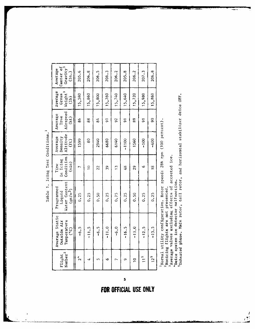
6. In-flight artificial icing, utilizing the HISS. was conducted in the vicinity ofFort Wainwright, Alaska, from 9 October through 3 November 1976. A total of9 icing flights were conducted in 10.6 flight hours, of which 3.2 hours were inthe artificial icing environment. The aircraft was iced at test conditions presentedin table I. Icing summaries for each flight are presented in appendix F. Flightlimitations contained in the operator's manual and the safety-of-flight release (refs 9and 10. app A) were observed during the testing.
4
FOR OFFICIAL USE ONLY
, /
w )> r o) 1 o --- ') Co r- Co
a)41mH0 0 0 0 CD 0 0 0 0
1u10& 0 0 0 0 0 0) 0 0) 0
co 00 '0 CD '0 -zT -1 N4 Co '5-1 O). a ~ CIO Co 0 fl r-. '0 r-. ON 00
'0 w -H
co P o C0 CoT a, OCa o a' a ~ C
co ~ a) c)
lz a)>110ro t4-1 Z 0 C0 0D 0 0 0 0 0 0
.- a C-H41-~ a' CY o -0 0o 0 '0 0 0: cp ( ~ -,q t4 Lt) a' 'D0 - *T C -w z " ' - N1 '0 ' - I I co> ) -4 Z
w 0
'04 J 00H 0u -. H r- 0D Nl a' % o a 0 00 N 4
to E ' .
4__J j.) ou o
~~~~~~ 410 U ~ LI f f
01 0 0 0 0 7 0 oC)- 4
tfl 0 U U - 4 L() 0N 0- 04t 0 ') U14 r_- =
Cc d-4 '0 -r '0 u 'o'0 t N ~ JE-: , .: " ; c c;* ; Ma00
4 o- 0~ 41 o
4J Z c 4
tfl. N-4 t 0 t- a' 0c -D Nn c 4W~~ -, Q) >,a l)-, a
-i N
*
54 u
4~ (1 -k p.- -i -1
TEST METHODOLOGY
7. Artificial icing of thc YUH-6 IA was conducted b l\ ing the test aircraftin a spray cloud generated by the HISS. A detailed discussion of the test sequenceand procedures is contained in reference 3. appendix A. Prior to entering the cloud.the test aircraft was stabilized at the predetermined test conditions and base-linetrim data were recorded. The test aircraft %as then immerscd in the spray cloud.After ice accumulation the test aircraft was again stibili/ed outside the spray cloudat the initial trim airspeed and another data record taken. The ice accretion wasthen documented by photographic and visual observation. Following data recording.a steady-state autorotat',on was performed to determine rotor speed degradationwith ice accretion. Immersion times were based on pilot judgment, systemoperation, power required. vibration, visual observations, duration of the HISS watersupply, and prior test results.
8. A detailed description of test instrumentation and special equipment installedon the test aircraft is presented in appendix D. In addition to the Rosemountice detector integral to the deice system (app B). additional systems manufacturedby Rosemount Engineering Company and Norrnalair-Garrett Ltd, and aUSAAEFA-designed and fabricated visual probe were installed to measure iceseverity and accretion. Brief descriptions of the Rosemount and Garrett systemsare presented in appendix D and a detailed discussion can be found in references I Iand 12, appendix A. The USAAEFA visual ice accretion probe is discussed inparagraph 18. appendix D. and sl.own in photo 6. appendix D.
9. Test techniques and data analysis methods are presented in appendix E. AHandling Qualities Rating Scale (HQRS). the methods used to determine HISS spraycloud parameters, and definitions of icing types and severities are also presentedin appendix E.
6
FOR OFFICIAL USE ONLY
• /
RESULTS AND DISCUSSION
GENERAL
10. An in-flight artificial icing evaluation of the YUH-61A was conducted todetermine the capability of the aircraft to fly in icing conditions without a deicesystem and to determine the potential effectiveness of the contractor-provided deicesystem. The effectiveness of the windshield, pitot-static, engine, and engine airinduction anti-ice systems was also evaluated. The ice accretion and sheddingcharacteristics of the YUH-61A airframe and flight control surfaces weredocumented. The capabilities of two special equipment ice detectors to detect andmeasure icing conditions were evaluated. Ice accretion on the airframe and flightcontrol surfaces during the unheated blade phase caused significant increases inpower required for level flight and significant decreases in autorotational rotor speedwith collective full-down. Additionally, random asymmetrical shedding of ice fromthe main rotor blades caused increased airframe vibration levels and there wasdamage from ice impact on the tail rotor gearbox fairing and tail rotor blades.The aircraft does not possess the capability to safely operate in an icing environmentwithout a main rotor deice system. With the deicing system functioning, theYUH-61A successfully flew in artificial icing conditions for periods of time upto 48 minutes, and displays excellent potential for operating in a moderate icingcondition. Three deficiencies were noted which should be corrected prior to flightin icing conditions. These deficiencies are the inability to activate the deice systemfollowing an ice detector malfunction: the lack of a system to monitor the integralparticle separator (IPS) turbine operation: and the erratic and unreliable pitot-staticindications in level and climbing flight caused by the irregular ice accretion patternson the lower front fuselage area. Nine shortcomings which degraded crew or aircraftoperation were noted. Following correction of the three defiliencies. testing ofthe deice system in natural icing conditions should be conducted to validate theice accretion and shedding characteristics and aircraft performance characteristicsobserved during this evaluation.
DEICE SYSTEM OPERATION
II. The YUH-61A deice system was evaluated for operational characteristics.electrical switching transients, and electrical power requirements during the heatedblade phase. During 2.8 hours of flight time in the artificial icing environment,the deice system automatically cycled 58 times with only two malfunctions. Asystem cycle consisted of four ice accretion signals from the ice detector, followedby twelve electrical power pulses distributed to the deice system heating blankets.The only component change was the deice system ice detector, which malfunctionedduring the first icing flight (para 12). One automatic system shutdown, initiatedby the system fault detection circuitry, occurred (para 13). The heating blankets
7
FOR OFFICIAL USE ONLY
, /
on the main and tail rotor blades were installed during the construction of theblades. These blankets required no maintenance, although the main rotor bladeshad accumulated 163, 115, 21, and zero hours, respectively, and the tail rotorblades had accumulated 409, 409, 210, and 210 hours, respectively, prior to theicing tests.
12. Automatic cycling of the deice system was accomplished by the deicecontroller, which received an icing signal (pulse) from the system ice detector.The pulse signals were sent from the ice detector when a predetermined thicknessof ice was accumulated. The ice detector probe was then readied for another iceaccumulation (icing signal) by electrically heating the probe and shedding the ice.During the first icing flight, ice continuously accumulated on the probe due toa failure of the probe heating element. Therefore, the ice detector was unableto send repeated icing signals to the deice controller as required for systemoperation. The system incorporated no provisions to automatically or manuallyactivate the system if the ice detector malfunctioned. Failure of the ice detectorheating circuit renders the deice system inoperable. The inability to activate thedeice system following an ice detector malfunction is a deficiency.
13. As discussed in the system description in appendix B. the deice system containsfault detection logic which deactivates the system and illuminates theROTOR DEICE caution panel light on the annunciator panel when a fault isdetected. One incident of this light illuminating occurred after a cloud immersionof 30 minutes at -16.5°C and a liquid water content (LWC) of 0.25 grams percubic meter (gminm 3 ). The aircraft immediately exited the cloud and the deicesystem ROTOR/STAB switch was cycled OFF and ON. The caution lightextinguished and the aircraft reentered the icing environment for an additional18 minutes (three system cycles) without further incident. The failure could notbe duplicated and did not occur during the remaining tests. Postflight inspectionof the system and analysis of the available data indicated an electrical powertransient was the probable cause for the momentary system failure. An investigationshould be conducted by Boeing Vertol to determine the cause of the illuminationof the ROTOR DEICE caution light.
14. Engagements and disengagements of the rotor deice system were conductedto evaluate the effects of electrical switching transients. The tests were accomplishedon the ground and in flight with all anti-ice systems and both stability and controlaugmentation systems (SCAS) ON. When the ROTOR/STAB switch was placedON or OFF, the vertical situation indicator exhibited a rapid ±3-degree transientroll attitude oscillation and a ± 150-foot transient oscillation was observed on theradar altimeter needle. Both indicators returned to their original position followingthe momentaiy oscillation with no input to SCAS or airframe. Placing the deiceROTOR/STAB switch ON or OFF while on the ground at 100 percent rotor speedresulted in a mild transient airframe vertical response. This response required nopilot compensation or reaction. In flight, no airframe or SCAS response wasobserved following a deice system engagement or disengagement. No other system
8
FOR OFFICIAL USE ONLY
I
. .. . .. -/

interference problems were observed with operation of the deice system. The mildswitching transients when the deice system is engaged or disengaged are ashortcoming.
15. The electrical power requirements of the deice system were monitored in flightusing the generator load meters and were calculated from recorded data followingeach flight. The electrical power required to operate the main rotor blades rangedfrom 19.1 to 20.3 kilovolt-amperes (KVA). The electrical power required for thetail rotor was 8 to 8.5 KVA and 11.4 to 12 KVA for the horizontal stabilizer.Since electrical power was not sent simultaneously to the main and tail rotorsand the horizontal stabilizer, the maximum load to operate the deice system was20.3 KVA. This electrical power requirement was 50 percent of the maximumcontinuous generator rating (41 KVA) of a single generator and closelyapproximated the Boeing Vertol pretest estimate of 20.7 KVA. Within the scopeof this test, the electrical power requirements of the deice system were satisfactory.
16. The electrical power pulse duration during each cycle of the deice systemwas measured from recorded data. The pulse duration was automatically variedby the deice controller as a function of total air temperature and varied from3.6 seconds at -5°C to I I seconds at -I 5C. The variation of pulse duration observedwas in agreement with Boeing Vertol pretest estimates. No adjustment to the pulseduration was required during this evaluation, since control of heated surface iceaccretion and shedding on the main rotor blade was satisfactory (paras 34 and 36).
ANTI-ICE AND HEATING SYSTEMS OPERATION
General
17. Throughout the tests the anti-ice systems, cabin heating, and associatedsubsystems were continuously evaluated. The operating characteristics of thesesystems were the same for both the heated and unheated phases.
Engine Anti-ice
18. Engine anti-icing was accomplished by a combination of hot axial compressordischarge air and heat transfer from the air/oil cooler in the engine frame. Operationof the system was controlled by the ENG INLET switch located on the overheadswitch panel. A detailed discussion of the system is presented in appendix B. Duringboth phases of testing the system operated without any failures and with nounscheduled maintenance being required. Within the scope of this test, the engineanti-ice system is satisfactory.
9
FOR OFFICIAL USE ONLY
, /
Engine Air Induction Anti-ice
Engine Inlet (D-ring) Fairing:
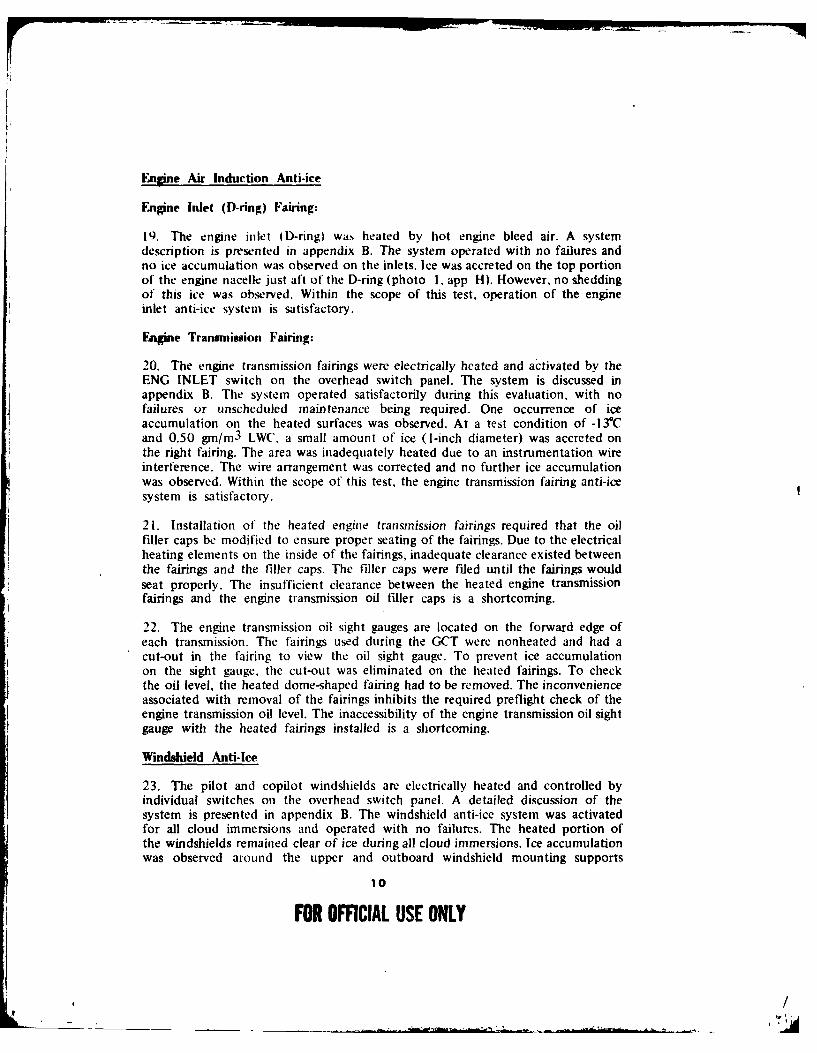
19. The engine inlet (D-ring) was heated by hot engine bleed air. A systemdescription is presented in appendix B. The system operated with no failures andno ice accumulation was observed on the inlets. Ice was accreted on the top portionof the engine nacelle just aft of the D-ring (photo 1, app H). However, no sheddingof this ice was observed. Within the scope of this test, operation of the engineinlet anti-ice system is satisfactory.
Engine Transmninion Fairing:
20. The engine transmission fairings were electrically heated and activated by theENG INLET switch on the overhead switch panel. The system is discussed inappendix B. The system operated satisfactorily during this evaluation, with nofailures or unscheduled maintenance being required. One occurrence of iceaccumulation on the heated surfaces was observed. At a test condition of -13°Cand 0.50 gn/m3 LW(', a small amount of ice (I-inch diameter) was accreted onthe right fairing. The area was inadequately heated due to an instrumentation wireinterference. The wire arrangement was corrected and no further ice accumulationwas observed. Within the scope of this test, the engine transmission fairing anti-icesystem is satisfactory.
21. Installation of the heated engine transmission fairings required that the oilfiller caps be modified to ensure proper seating of the fairings. Due to the electricalheating elements on the inside of the fairings, inadequate clearance existed betweenthe fairings and the filler caps. The filler caps were filed until the fairings wouldseat properly. The insufficient clearance between the heated engine transmissionfairings and the engine transmission oil filler caps is a shortcoming.
22. The engine transmission oil sight gauges are located on the forward edge ofeach transmission. The fairings used during the GCT were nonheated and had acut-out in the fairing to view the oil sight gauge. To prevent ice accumulationon the sight gauge, the cut-out was eliminated on the heated fairings. To checkthe oil level, the heated dome-shaped fairing had to be removed. The inconvenienceassociated with removal of the fairings inhibits the required preflight check of theengine transmission oil level. The inaccessibility of the engine transmission oil sightgauge with the heated fairings installed is a shortcoming.
Windshield Anti-Ice
23. The pilot and copilot windshields are electrically heated and controlled byindividual switches on the overhead switch panel. A detailed discussion of thesystem is presented in appendix B. The windshield anti-ice system was activatedfor all cloud immersions and operated with no failures. The heated portion ofthe windshields remained clear of ice during all cloud immersions. Ice accumulationwas observed around the upper and outboard windshield mounting supports
10
FOR OFFICIAL USE ONLY
, /
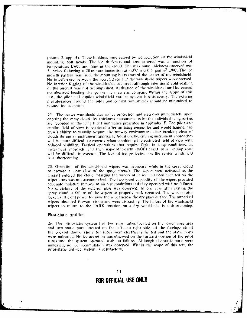
(photo 2, app 1). These buildups were caused by ice accretion on the windshieldmounting bolt heads. The ice thickness and area covered was a function oftemperature, LWC, and time in the cloud. The maximum thickness observed was
3 inches following a 20-minute immersion at -13C and 0.5 gm/ill 3 LWC. The icegrowth pattern was from the mounting bolts toward tile center of the windshield.No interference between the accreted ice and the windshield wipers was observed.No interior fogging of the windshields occurred, although intentional cold soakingof the aircraft was not accomplished. Activation of the windshield anti-ice causedno observed heading change on "'., magnetic compass. Within the scope of thistest, the pilot and copilot windshield anti-ice systen is satisfactory. The exteriorprotuberances around the pilot and copilot windshields should be minimized toreduce ice accretion.
24. The center windshield has no ice protection and iced over immediately uponentering the spray cloud. Ice thickness measurements for the individual icing sortiesare recorded in the icing flight summaries presented in appendix F. The pilot andcopilot field of view is restricted after an icing encounter and would hamper thecrew's ability to visually acquire the runway environment after breaking clear ofclouds during an instrument approach. Additionally, circling instrument approacheswill be more difficult to execute when combining the restricted field of view withreduced visibility. tactical operations that require flight in icing conditions, aninstnlimcnt approach. and then nap-of-the-earth (NOE) flight to a landing zonewill be difficult to executc. The lack of' ice protection on the center windshieldis a shortcoming.
25. Operation of the windshield wipers was necessary while in the spray cloudto provide a clear view of the spray aircraft. The wipers were activated as theaircraft entered the cloud. Starting the wipers after ice had been accreted on thewiper arms was not accomplished. The two-speed capability of the wipers providedadequate moisture removal at ali test conditions and they operated with no failures.No scratching of the exterior glass was observed. In one case after exiting thespray cloud, a failure o1 the wipers to properly park occurred. The wiper motorlacked sufficient power to move the wiper across the dry glass .urface. The unparkedwipers obscured forward vision and were distracting. The failure of the windshieldwipers to return to the PARK position on a dry windshield is a shortcoming.
Pilot-Static Anti-h'e
20. The pitot-static systel had two pitot tubes located on the lower nose areaand two static ports located on the left and right sides of the fuselage aft ofthe cockpit doors. The pitot tubes were electrically heated and the static portswere unheated. No ice accretion was observed on the forward portion of the pitottubes and the system operated with no failures. Although tile static ports wereunheated, no ice accumulation was observed. Within the scope of this test, tilepitot-static anti-ice system is satisfactory.
11
FOR OFFICIAL USE ONLY
/
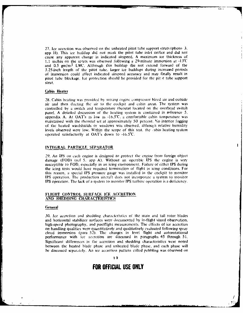
27. Ice accretion was observed on the unheated pitot tube support struts (photo 3.app H). This ice buildup did not mask the pitot tube inlet orifice and did notcause any apparent change in indicated airspeed. A maximum ice thickness of1.1 inches on the struts was observed following a 29-minute immersion at -13°Cand 0.5 gm/inm 3 LWC. Although this buildup diu not extend forward of the3.25-inch length of the pitot tube, larger ice buildups during increased periodsof immersion could affect indicated airspeed accuracy and may finally result inpitot tube blockage. Ice protection should be provided for the pit t tube supportstrut.
Cabin Heater
28. Cabin heating was provided by mixing engine compressor bleed air and outsideair and then ducting the air to the cockpit and cabin areas. The system wascontrolled by a switch and temperature rheostat located on the overhead switchpanel. A detailed discussion of the heating system is contained in reference 5.appendix A. At OAT's as low as -16.5°C, a comfortable cabin temperature wasmaintained with the rheostat set at approximately 50 percent. No interior foggingof the heated windshields or windows was observed, although relative humiditylevels observed were low. Within the scope of this test, the cabin heating systemoperated satisfactorily at OAT's down to -16.5 0C.
INTEGRAL PARTICLE SEPARATOR
29. An IPS on each engine is designed to protect the engine from foreign objectdamage (FOD) (ref 5, app A). Without an operable IPS the engine is ven.susceptible to FOD, especially in an icing environment. Failure of either IPS duringthe icing tests would have required termination of flight in icing conditions. Forthis reason, a special IPS pressure gauge was installed in the cockpit to monitorIPS operation. 'The production aircraft does not incorporate a system to monitorIPS operation. The lack of a system to monitor IPS turbine operation is a deficiency.
FLIGHT CONTROL SURFACE ICE ACCRETIONAND SHEDDING CHARACTERISTICS
General
30. Ice accretion and shedding charactcristics of the main and tail rotor bladesand horizontal stabilizer surfaces were documented by in-flight visual observation.high-speed photography, and postflight measurements. The effects of ice accretionon handling qualities were quantitatively and qualitatively evaluated following spraycloud immersion (para 52). The changes in level flight and autorotationalperformance with ice accretion are discussed in paragraphs 45 through 51.Significant differences in the accretion and shedding characteristics were notedbetween the heated blade phase and unheated blade phase, and each phase willbe discussed separately. An ice accretion pattern called pebbling was observed on
12
FOR OFFICIAL USE ONLY
,I
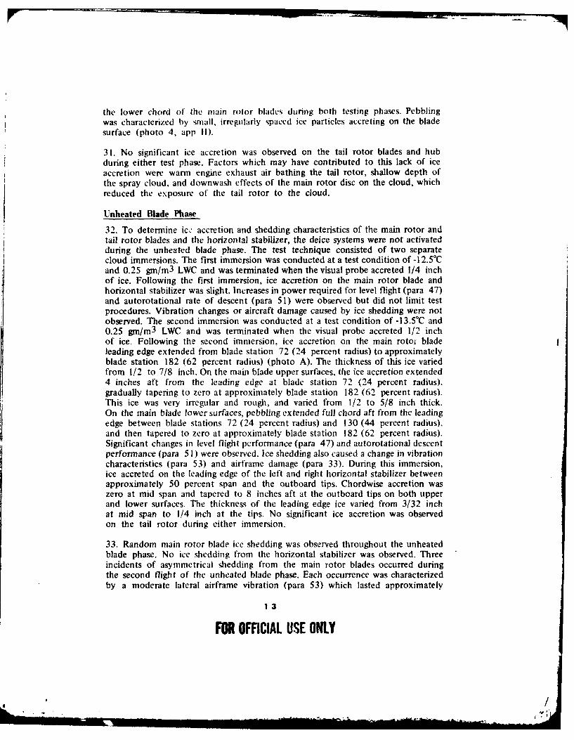
the lower chord of the main rotor blades during both testing phases. Pebblingwas characterized by small, irregularly spaced ice particles accreting on the bladesurface (photo 4, app i1).
31. No significant ice accretion was observed on the tail rotor blades and hubduring either test phase. Factors which may have contributed to this lack of iceaccretion were warm engine exhaust air bathing the tail rotor, shallow depth ofthe spray cloud, and downwash effects of the main rotor disc on the cloud, whichreduced the exposure of the tail rotor to the cloud.
Unheated Blade Phase
32. To determine ic " accretion and shedding characteristics of the main rotor andtail rotor blades and the horizontal stabilizer, the deice systems were not activatedduring the unheated blade phase. The test technique consisted of two separatecloud immersions. The first immersion was conducted at a test condition of -l 2.5°Cand 0.25 gmn/m3 LWC and was terminated when the visual probe accreted 1/4 inchof ice. Following the first immersion, ice accretion on the main rotor blade andhorizontal stabilizer was slight. Increases in power required for level flight (para 47)and autorotational rate of descent (para 51) were observed but did not limit testprocedures. Vibration changes or aircraft damage caused by ice shedding were notobserved. The second immersion was conducted at a test condition of -13.5°C and0.25 gm/m 3 LWC and was terminated when the visual probe accreted 1/2 inchof ice. Following the second immersion, ice accretion on the main rotoi bladeleading edge extended from blade station 72 (24 percent radius) to approximatelyblade station 182 (62 percent radius) (photo A). The thickness of this ice variedfrom 112 to 718 inch. On the main blade upper surfaces, the ice accretion extended4 inches aft from the leading edge at blade station 72 (24 percent radius).gradually tapering to zero at approximately blade station 182 (62 percent radius).This ice was very irregular and rough, and varied from 1/2 to 5/8 inch thick.On the main blade lower surfaces, pebbling extended full chord aft from the leadingedge between blade stations 72 (24 percent radius) and 130 (44 percent radius),and then tapered to zero at approximately blade station 182 (62 percent radius).Significant changes in level flight performance (para 47) and autorotational descentperformance (para 5 1) were observed. Ice shedding also caused a change in vibrationcharacteristics (para 53) and airframe damage (para 33). During this immersion,ice accreted on the leading edge of the left and right horizontal stabilizer betweenapproximately 50 percent span and the outboard tips. Chordwise accretion waszero at mid span and tapered to 8 inches aft at the outboard tips on both upperand lower surfaces. The thickness of the leading edge ice varied from 3/32 inchat mid span to 1/4 inch at the tips. No significant ice accretion was observedon the tail rotor during either immersion.
33. Random main rotor blade ice shedding was observed throughout the unheatedblade phase. No ice shedding from the horizontal stabilizer was observed. Threeincidents of asymmetrical shedding from the main rotor blades occurred duringthe second flight of the unheated blade phase. Each occurrence was characterizedby a moderate lateral airframe vibration (para 53) which lasted approximately
13
FOR OFFICIAL USE ONLY
/tV
, . ,
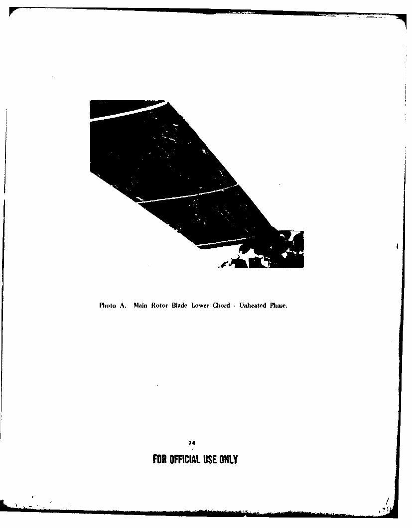
Photo A. Main Rotor Blade Lower Chord -Unheated Phase.
14
FOR OFFICIAL USE ONLY
I minute. Flight control inputs by the pilot were not required to maintain adequateaircraft control during the asymmetrical sheds (HQRS 2). During landing and engineshutdown following this flight, numerous ice particles were observed shedding fromthe main rotor blades. The ice was shed in all directions and presented a potentialhazard to ground personnel in the vicinity of the helicopter. The WARNING shownbelow should be placed in the operator's manual. Damage to the tail rotor gearboxfairing on the vertical fin was observed following this flight. Ice particles alsoimpacted on the tail rotor blades, causing three blade skin deformations. The tailrotor blade strikes did not require blade replacement.
WARNING
Following flight into icing conditions, ice shed from therotor blades and/or other rotating components presentsa hazard to personnel during ground operation andshutdown of the helicopter. Ground personnel shouldremain well clear of the helicopter during landing, groundoperation, and shutdown. Passengers/crewmembers shouldnot exit the helicopter until the rotor has stopped.
Heated Blade Phase
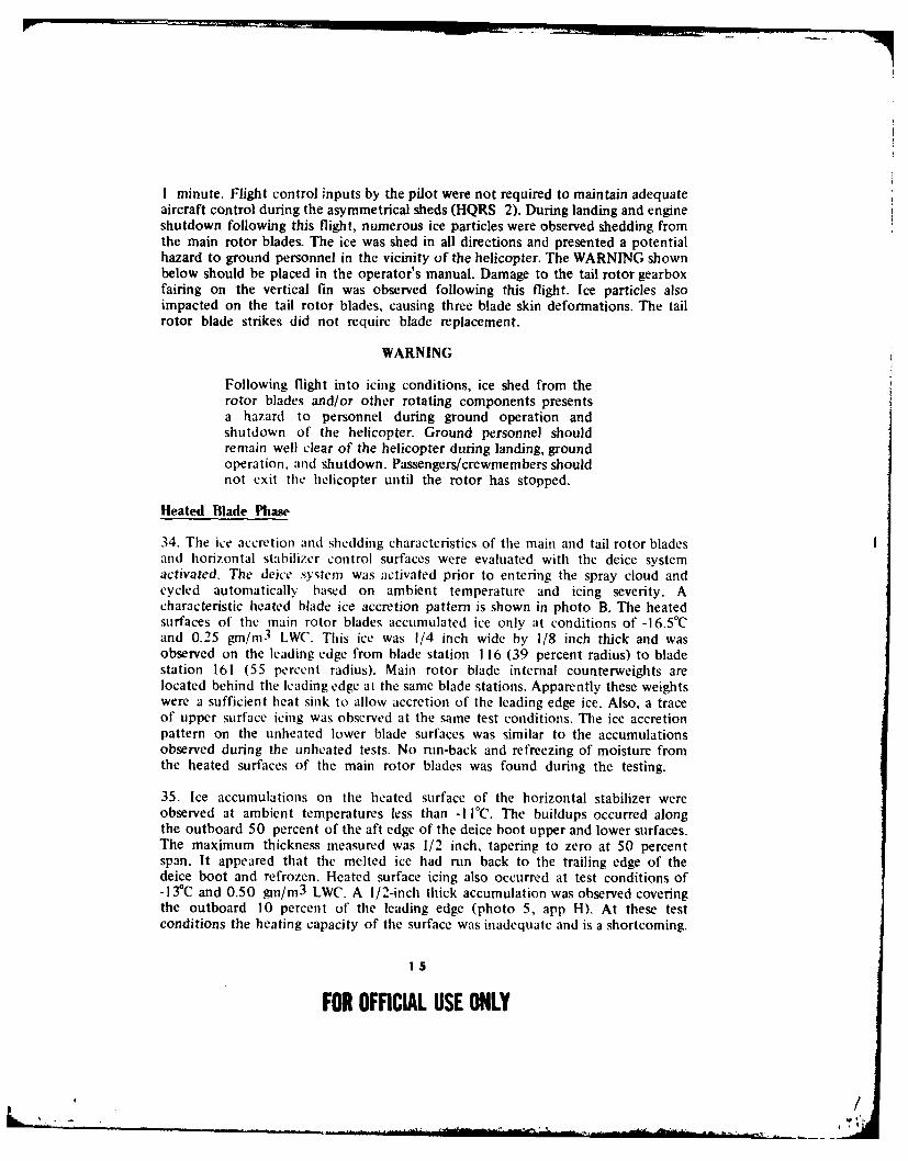
34. The ice accretion and shedding characteristics of the main and tail rotor bladesand horizontal stabilizer control surfaces were evaluated with the deice systemactivated. The deice system was activated prior to entering the spray cloud andcycled automatically based on ambient temperature and icing severity. Acharacteristic heated blade ice accretion pattern is shown in photo B. The heatedsurfaces of the main rotor blades accumulated ice only at conditions of -16.5°Cand 0.25 gm/r 3 LWC. This ice was 1/4 inch wide by 1/8 inch thick and wasobserved on the leading edge from blade station 116 (39 percent radius) to bladestation 161 (55 percent radius). Main rotor blade internal counterweights arelocated behind the leading edge at the same blade stations. Apparently these weightswere a sufficient heat sink to allow accretion of the leading edge ice. Also, a traceof upper surface icing was observed at the same test conditions. The ice accretionpattern on the unheated lower blade surfaces was similar to the accumulationsobserved during the unheated tests. No nm-back and refreezing of moisture fromthe heated surfaces of the main rotor blades was found during the testing.
35. Ice accumulations on the heated surface of the horizontal stabilizer wereobserved at ambient temperatures less than -I I°C. The buildups occurred alongthe outboard 50 percent of the aft edge of the deice boot upper and lower surfaces.The maximum thickness measured was 1/2 inch, tapering to zero at 50 percentspan. It appeared that the melted ice had run back to the trailing edge of thedeice boot and refrozen. Heated surface icing also occurred at test conditions of-13"C and 0.50 gmn/m3 LWC. A 1/2-inch thick accumulation was observed coveringthe outboard 10 percent of the leading edge (photo 5, app I). At these testconditions the heating capacity of the surface was inadequate and is a shortcoming.
15
FOR OFFICIAL USE ONLY
k, /
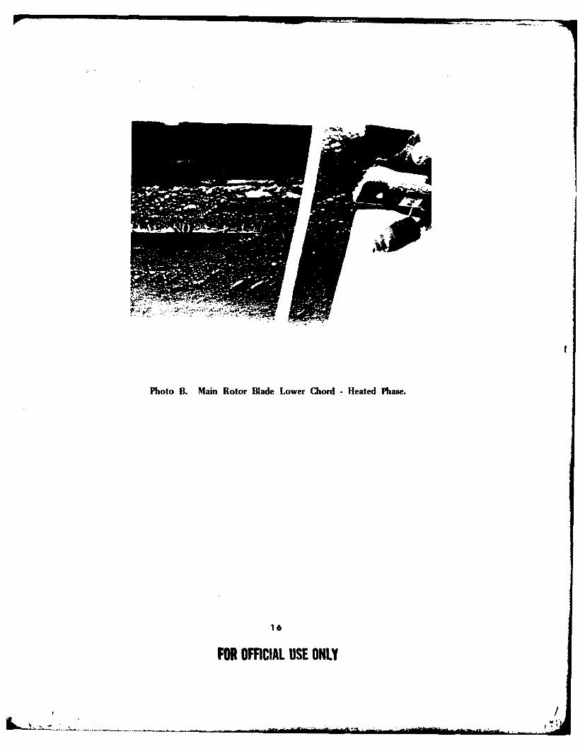
Photo B. Main Rotor Blade Lower Chord - Heated Phase.
16
FOR OFFICIAL USE ONLY
, /

36. Ice shedding during cycling of the deice system caused no observed changesin handling qualities, vibration characteristics, or power management. The iceparticles shed from the heated surfaces were observed to be extremely small andpresented no FOD hazard to the engines, airframe, or rotating flight controlsurfaces.
AIRFRAME ICE ACCRETION ANDSHEDDING CHARACTERISTICS
37. Airframe ice accretion and shedding characteristics were documented by in-flightvisual observation, high-speed photography, and postflight measurements. Theeffects of ice accumulation on handling qualities were quantitatively andqualitatively evaluated (para 52). The changes in level flight and autorotationalperformance with ice accretion are discussed in paragraphs 45 through 51. Thesame airframe accretion and shedding characteristics were noted during both theheated and unheated blade phases.
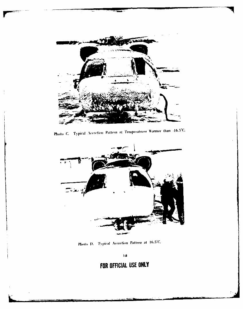
38. The majority of the ice accreted on the airframe occurred in the forwardfuselage area. Negligible ice was accreted on the fuselage sides, fuselage bottom,upper fuselage (except the forward crown). engine nacelles, and tail boom. Therewere two types of glime ice accretion patterns (characteristics) observed. The iceaccretion pattern at temperatures warmer than -16.50 C was characterized by a roughsurface with numerous irregularities (photo C). As the time in the cloud wasincreased, these irregularities grew in size, forming vertical columns of ice whichgrouped together to create. ice ridges. The ice ridges were most pronounced onthe chin bubbles, lower nose area, and pilot foot-steps. The second distinctivepattern was the ice formation at a temperature of -16.5°C. which was characterizedby a generally smooth uniform surface with no ice ridge formations (photo D).The ice particles on the fuselage were smaller and more numerous, which creitedthe smoother, more regular-textured surface.
39. Following an immersion of 29 minutes at -130 C and 0.50 gm/rn 3 LWC, erraticand erroneous ship's system pitot-static indications were observed in level andclimbing flight. The first indication of a pitot-static system error was noted duringthe postcloud level flight performance test. Random airspeed fluctuations of ± I to3 knots were observed on the pilot sensitive airspeed indicator. These airspeedchanges were not seen on the copilot production-type indicator. After the levelflight performance data were obtained, a climb was initiated at 90 knots indicatedairspeed (KIAS) to gain altitude to conduct the autorotational performance tests.As the rate of climb increased to 800 feet per minute (ft/min), the indicatedairspeed decreased to approximately 60 KIAS in a level pitch attitude. At a rateof climb of 1000 ft/min, indicated airspeed rapidly decreased to zero. Thiserroneous airspeed information was received by the SCAS and resulted in an increasein the horizontal stabilizer incidence angle. This caused the aircraft to pitch downand required an aft longitudinal input of approximately 0.5 inch to maintain alevel pitch attitude (HQRS 7). Cruise guide indicator readings of 100 and130 percent were observed at rates of climb of 800 and 1000 ft/min, respectively.
17
FOR OFFICIAL USE ONLY
, /
A~Jr
photo C. Tvpical Accretion Pattern at Temperatures Warmer than -16.7)'C.
Photo 1). Ty'vpical Accretion Pattern at 1 6.51C.
FOR OFFICIAL USE ONLY
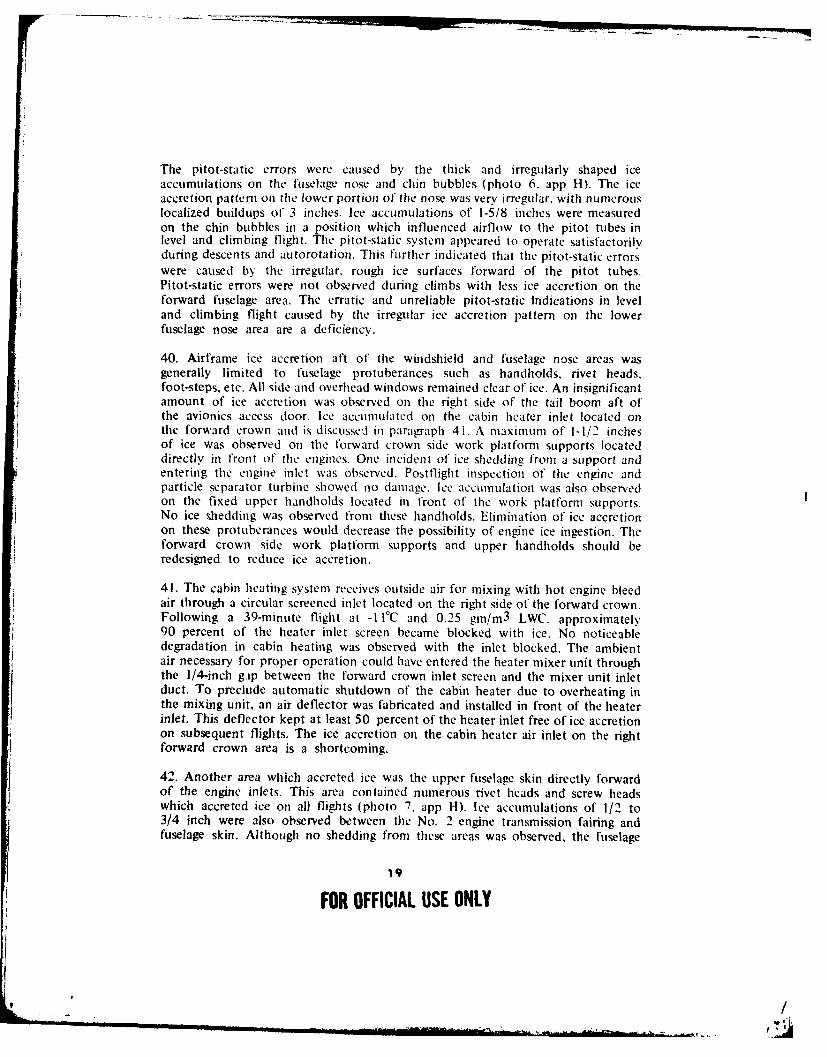
The pitot-static errors were caused by the thick and irregularly shaped iceaccumulations on the fuselage nose and chin bubbles (photo 6. app H). The iceaccretion pattern on the lower portion of the nose was very irregular, with numerouslocalized buildups of 3 inches. Ice accumulations of 1-5/8 inches were measuredon the chin bubbles in a position which influenced airflow to the pitot tubes inlevel and climbing flight. The pitot-static system appeared to operate satisfactorilyduring descents and autorotation. This further indicated that the pitot-static errorswere caused b the irregular. rough ice surfaces forward of the pitot tubes.Pitot-static errors were not observed during climbs with less ice accretion on theforward fuselage area. The erratic and unreliable pitot-static Indications in leveland climbing flight caused by the irregular ice accretion pattern on the lowerfuselage nose area are a deficiency.
40. Airframe ice accretion aft of the windshield and fuselage nose areas wasgenerally limited to fuselage protuberances such as handholds, rivet heads,foot-steps, etc. All side and overhead windows remained clear of ice. An insignificantamount of ice accretion was observed on the right side of the tail boom aft ofthe avionics access door. Ice accumulated on the cabin heater inlet located onthe forward crown and is discusseJ in paragraph 4i. A maximum of 1-1/2 inchesof ice was observed on the forward crown side work platform supports locateddirectly in front of the engines. One incident of ice shedding from a support andentering the engine inlet was observed. Posttlight inspection of the engine andparticle separator turbine showed no damage. Ice accumulation was also observedon the fixed upper handholds located in front of the work platform supports.No ice shedding was observed from these handholds. Elimination of ice accretionon these protuberances would decrease the possibility of engine ice ingestion. Theforward crown side work platform supports and upper handholds should beredesigned to reduce ice accretion.
41. The cabin heating system receives outside air for mixing with hot engine bleedair through a circular screened inlet located on the fight side of the forward crown.Following a 39-minute flight at -1 I°C and 0.25 gm/m 3 LWC. approximately90 percent of the heater inlet screen became blocked with ice. No noticeabledegradation in cabin heating was observed with the inlet blocked. The ambientair necessary for proper operation could have entered the heater mixer unit throughthe 1/4-inch gip between the forward crown inlet screen and the mixer unit inletduct. To preclude automatic shutdown of the cabin heater due to overheating inthe mixing unit, an air deflector was fabricated and installed in front of the heaterinlet. This deflector kept at least 50 percent of the heater inlet free of ice accretionon subsequent flights. The ice accretion on the cabin heater air inlet on the rightforward crown area is a shortcoming.
42. Another area which accreted ice was the upper fuselage skin directly forwardof the engine inlets. This area contained numerous rivet heads and screw headswhich accreted ice on all flights (photo 7, app H). Ice accumulations of 1/2 to3/4 inch were also observed between the No. 2 engine transmission fairing andfuselage skin. Although no shedding from these areas was observed, the fuselage
19
FOR OFFICIAL USE ONLY
II.
skin protuberances forward of the engine inlets should be reduced to decrease thelikelihood of ice ingestion by the engine.
43. Operation of the unheated ship's OAT probe was evaluated prior to and duringcloud immersion. Maximum ice accumulations of 1-3/4 inches were observedcovering 75 percent of the probe surface. No degradation in the OAT probeperformance was noted with ice accretion. Within the scope of this test, the ship'sstandard OAT probe is satisfactory for use in an icing environment.
44. Minimal ice shedding was observed from ice accumulations on the airframe.Generally, ice which shed from the nose area below the windshields departed theairframe outboard and down, away from the aircraft. Numerous ice sheddings fromthe windshield wiper arms did occur. These particles ranged in size from 1/2 to1-1/2 inches in diameter. The trajector\ was normally outboard and aft along thefuselage below the engine inlets. One incident of center windshield shedding wasobserved when the aircraft descended into warmer temperatures. A piece ofapproximately 3/4 square foot in area departed upward and impacted with themain rotor blades. There was no blade damage and no engine ice ingestion wasobserved.
LEVEL FLIGHT PERFORMANCE
45. Level flight performanc,2 data %kcrc obtaiticd during both test phases todetermine the change in engine power required %ith airfratne and flight controlsurface ice accretion. The tests for each phase %%'re conducted at the test conditionsshown in table I. Data were first obtained prior to entering the icing environmentand again after exiting the spray cloud. A summary of the level flight performanceresults for both test phases is presented in table 2
46. During the heated blade phase an increase in engine shaft horsepower (shp)required with ice accretion was noted. The changes in power required were afunction of time in the icing environment, ambient temperature, programmed LWC,and change in gross weight due to fuel birloff and ice accretion. At no timeduring the testing did the power required to safely operate in an icing environmentwith all deice/anti-ice systems operating become a limiting factor. However, thelevel flight performance data show that even with a functioning deice system adegradation in range and endurance can be expected. Within the scope of thistest, a quantitative level flight performance assessment was not made.
47. During the unheated blade phase, significant power-required increases withice accretion were noted. A comparison of the heated and unheated phases atsimilar conditions of temperature and LWC shows that a substantial portion ofthe power increase was attributable to ice accretion on the main rotor blades.These changes in power required represent a significant level flight performancedegradation with ice accretion. The full impact of this degradation on the missionprofile was not determined.
20
FOR OFFICIAL USE ONLY
, , /

~0
0 (1) 0
C14 cn 00r ej .4U4 41 4f4 4) (1) kn&~
0
00i 00rnr- 0'U) ' r- .-
L)04 -,4 -4 u)- . . N G
u ' 0 0 0 C0 0 0% 0m0
c: 1-J 1- .CN T 0 -I Gl -4 %.0 -It Lo
0- r4 r-) CO0 '0 0I
0O4-4--inLID LIPI LW Lo Q) :3
Q-0 4 ' - - AL
Q) ca
'e 14 a)
> 0 4.) c
U 4 0CD- 0 1 a% - n 00 CA 0 3 0
C4 E-4 P. I, -0 -a)0
4j0
4-4O LM C -U' 0 0 c
0) 0U >1
co 0~ 0 4) -u
W W -H 44 -0 a'% %D'.A H
a~ )-'- c: 00w4 0.r
>- (kE4'. ,4 "-4 m w
) 44 a) 0
0n (0 n L) o -4.3 4) -H CO -
d) (1l)C 0 bo
-. (N r-4 U W4 WN~ -
E- 0-4 0 0 V
Q) j4- uow
.21
FOR OFICA US OL
48. Single-engine topping tests were performed to determine the power-availableloss with activation of the anti-ice systems. The tests were conducted at threedifferent temperatures by retarding one engine condition lever (ECL) toSTART/IDLE and increasing collective pitch control until intermediate rated powerwas obtained on the operating engine. Data were obtained for each engine withand without the anti-ice systems operating and are presented in figures 1 and 2.appendix G. The average power-available loss with activation of the anti-ice systemswas 250 slip per engine for .he conditions tested. This represents 16 percent ofthe power available at -100C. sea-level conditions. Within the scope of this test,the engine power-available loss due to activation of the anti-ice systems did notlimit flight operations.
AUTOROTATIONAL PERFORMANCE
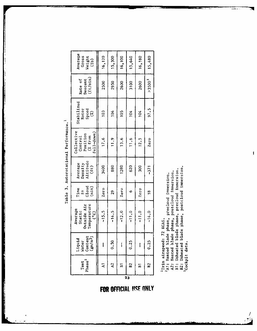
49. Autorotational descents were performed prior to and following spray cloudimmersions to evaluate the effect of airframe and flight control surface ice accretionon autorotational rotor speed and rate of descent. Autorotational descents wereconducted at 72 knots calibrated airspeed -KCAS) and maximum attainable rotorspeed, but not greater than 300 rpm ( 105 percent). Autorotational rate of descent.collective control position, and steady-state rotor speed were recorded to evaluatechanges in autorotational descent characteristics. A summary of autorotationaldescent performance is presented in table 3.
50. During the heated blade phase following a 29-minute immersion at testconditions of -13°C and 0.50 gmn/m3 LWC, autorotational rate of descent increasedfrom 2500 to 2950 ft/min. During this phase, the increase in rate of descent wasnot significant and, within the scope of this test, autorotational descent performanceis satisfactory.
5 1. During the unheated blade phase following an 18-minute immersion at -1 3.5°Cand 0.25 gm/inm 3 LWC, there was a significant increase in autorotational descentrate and a decrease in rotor speed with collective full-down. These changes wereattributed to a loss of aerodynamic efficiency of the main rotor blades and afuselage drag increase caused by ice accretion. Based on the progressive degradationof autorotational performance characteristics observed between the two unheatedblade phase flights, it was concluded that increased immersion times would causefurther rotor speed degradation, such that minimum safe autorotational rotor speed(90 percent) could not be maintained. The aircraft should be restricted from flightin icing conditions when a deice system is not installed and operating.
HANDLING QUALITIES
52. The effects of airframe and flight control surface ice accretion on aircrafthandling qualities were quantitatively and qualitatively evaluated during both testphases. Quantitative evaluation was accomplished by analysis of level flight controlpositions measured prior to, during, and following spray cloud immersion.
22
FOR OFFICIAL USE ONLY
, /[ , _ t .I,*
00 ) 41 C 0 0 0 0D C0M U)c.- 0 0 -.T m
-) C, -r -4
Q 4 .4 .- .
O~.40 0 0 c 0C C 0 0(1 r 0 Lt) 0 0 0 C0
a) u-- Lr) a7% '. D' Lfn41 U)J- 4 'J C, C14 C 4 ej c,
-It -t LI
*dJ. 000 0 CL-
'44 - 4 o
) r4 n -1 0
44 1-4 0 0 -o u PL. z
0
Cu Hi-. 0 0 0 0 4 0 -
$4j a) = j'.. e) c: 0o > Q) 4 Cu 0-H U)
4!0 -H U) w
e o c: 0 0 0
N -aZ-
-40 1-4 u 4-1
$4 Q) - 0) w w
0c .) -H ~ - L) Ld Q 0. 0. 0
0 ~~w 1-11-' - . -.Un)j w i. I I I I I I cn w0 0u 0
m uC 0. Im0 -4Q) 0)
.W -1' - -4 ,-40 cuC) * co .0 .
4We0 V)Lf) 0 4I A*- I * 03 -03 )
0 0 0; la.-a-u14-J -10 Ua- ) Q)) cu Cu a
Cu 4J J ) WCur
N
U) ) ') - C4 ,- CN ,4.......
23
FOR OFFCIAL 11%.F ONLY
Qualitative evaluation was accomplished during and following spray cloudimmersion while performing typical instrument flight maneuvers consisting of cruise,30-degree bank turns, and 500- to 1000-ft/min climbs and descents at 90 knotstrue airspeed (KTAS). The maximum control position change observed with iceaccretion was 4.3 percent (0.3 inch) in the left directional control, which occurredfollowing a 29-minute heated phase immersion at -13°C and 0.50 gm/m 3 LWC.This increase in left directional control corresponded to increased power requiredbecause of the accreted ice. This change was not noticeable to the pilot. Therewas no significant change in lateral or longitudinal control position. The onlyadverse handling quality observed during this evaluation was the aircraft pitch-downdiscussed in paragraph 39. No other adverse handling qualities attributable toairframe or flight control surface ice accretion and shedding were observed during
either test phase.
VIBRATION CHARACTERISTICS
53. The effects of ice accretion and shedding on aircraft vibration characteristicswere evaluated during both test phases. Qualitative evaluation was performed bythe test pilots and engineer. Quantitative data were sensed by accelerometersmounted at various places on the airframe (app D) and recorded on magnetic tape.These data were analyzed as described in paragraph 11. appendix E. During theheated blade phase of testing, no qualitative or quantitative changes in vibrationcharacteristics were observed during deice system operation or following spray cloudimmersion. During the unheated blade phase, the only change in vibrationcharacteristics occurred following asymmetric shedding of accumulated ice fromthe main rotor blades. The most pronounced chan e occurred following 8 minutesof immersion at -13.5°C and 0.25 gm/in- LWC when a moderateI-per-rotor-revolution (I/rev) lateral vibration was experienced. This objectionablevibration subsided approximately I minute later when additional ice was shed fromthe main rotor blade.
HUMAN FACTORS
54. The anti-ice and deice systems control panels were evaluated for location.arrangement, grouping, viewing distance and angles, labeling, and scaling. The pitotheat, engine anti-ice and windshield anti-ice controls were conveniently groupedtogether and clearly labeled on a single panel located on the overhead switch panel.This panel was conveniently arranged with the cabin heating and windshield wipercontrols (photo 8, app H). The deice control panel which contains the generatorload meters and blade deice control switches was located above the anti-ice panelon the overhead switch panel. The deice panel was arranged properly, but dueto the viewing angle from the pilot seats, the generator load meters could notreadily be seen. Observation of the load meter needles is required to monitor deicesystem operation. The inability to easily view the generator load meters on theoverhead switch panel is a shortcoming.
24
FOR OFFICIAL USE ONLY
, /
55. The health indicator test (tlIT) was a mandatory engine check prior to thefirst flight of the day. The test consists of setting an engine compressor speed(NG) based on OAT and comparing the indicated T4.5 with a base-line temperature.The operator's manual contains base-line temperatures for ambient conditions of-10C to +500 C. Outside air temperatures less than -10C were experiencedthroughout the icing tests. The lack of HIT data in the operator's manual fortemperatures less than -IOC precluded the accomplishment of an engine HIT checkand is a shortcoming.
56. No cockpit indication of icing severity conditions was provided. The pilot needsto know the icing severity encountered to prevent exceeding the deicing capabilityof the aircraft. A cockpit icing severity condition indicator should be installed.
ICE DETECTORS
General
57. Two special instrumentation ice detectors were installed on the test aircraftto correlate the icing severity levels experienced by the test aircraft with LWCestablished by the CH-47C spray aircraft. A Rosemount Model 871FA detectorwas provided by USAAEFA and a Normalair-Garrett detector was provided bythe manufacturer. These detectors were not an integral part of the deice systemand were evaluated separately. The ice detectors were mounted on an unheatedstructure located between the pilot door and the right gunner window (fuselagestation (FS) 85, right buttline (BL) 46, water line (WL) 150) (photo 3, app D).The detector location and the unheated structure for attaching the detectors tothe fuselage were factors which caused inaccurate icing severity indications on bothsystems at LWC's greater than 0.25 gmn/m3 .
Rosemount Ice Detector
58, The Rosemount Model 8711A ice detector provided accurate icing severityinformation at an LWC of 0.25 gm/rn 3 , but indicated higher than programmedat LWC's of 0.5 and 0.75 gm/ni3 . At an LWC of 0.25 gm/m3, the detectorindicated an icing severity of trace-to-light, which closely correlated with theprogrammed severity. Indications of moderate-to-heavy icing were observed at anLWC of 0.5 gmn/m3 and heavy to full needle deflection at an LWC of 0.75 gm/m 3 .Except at 0.25 gmn/m3 LWC, the detector indicated icing severity higher thanprogrammed. By comparison, data recorded from the Rosemount ice detectormounted on the fuselage nose showed that icing severity indications correlatedwith the programmed conditions established by the spray aircraft and the visualprobe. The test has shown that the Rosemount Model 871FA ice detector willprovide accurate icing severity information when properly located on the aircraft.
25
FOR OFFICIAL USE ONLY
-/
59. Occasional icing severities of moderate-to-heavy were seen with the aircraftclear of the spray cloud following immersion at LWC's of 0.5 and 0.75 gmnm3 .Additionally, moderate icing indications were periodically noted during nonicingflights. The cause of these erroneous indications was not determined.
Normalair-Garrett lee Detector
60. The Normalair-Garrett ice detector provided accurate icing severity informationat an LWC of 0.25 gmn/m3 . At LWC's of 0.5 and 0.75 gmn/m3, the detectorindicated LWC levels higher than programmed. At a programmed LWC of0.5 gmn/m3 , the detector indicated 0.5 to 2 gmn/m3 , with an average of 0.7 gmn/m3 .At a programmed LWC of 0.75 gmnm3, the detector indicated 1 to 2 gmn/m3 .These higher than programmed LWC indications follow the same trend observedon the Rosemount detector as discussed in paragraph 57. Moisture shed from thewindshield may have contributed to the erroneously high severity indications.
61. The Normalair-Garrett moisture sensing head was housed inside an unheatedstructure which directed air to the detector probe. Ice accumulations on thedetector inlet were observed. The resultant turbulence and restricted airflowpossibly interfered with the proper operation of the system. Additionally, erroneousicing severity indications of 0.6 to I gmn/m3 were observed out of the icingenvironment after ice had accumulated on the probe housing and the fuselagedetector attachment structure. At the selected fuselage location, theNormalair-Garrett ice detector provided accurate indications of icing severity onlyat an LWC of 0.25 gmnm3 .
26
FOR OMCIAL USE ONLY
, /V .'
-. ... .. ... . .. . . .. - " . m i i~ llll l I ., "

CONCLUSIONS
GENERAL
62. The Boeing Vertol YUH-61A does not possess the capability to safely operatein an icing environment without a rotor deice system.
63. Within the scope of this test. the YUH-61A with an nnti-ice/deice systemdisplays excellent potential for operating in a moderate icing environment.
64. The following specific conclusions were reached upon completion of theYUH-61A artificial icing tests:
a. The electrical power requirements of the deice system closelyapproximated the design estimates (para 15).
b. The engine, engine inlet (D-ring) fairing, engine transmission fairing,windshield, and pitot-static anti-ice systems operated satisfactorily (paras 18, 19,20, 23, and 26).
c. The cabin heating system operated satisfactorily at OAT's down to-16.5°C (para 28).
d. Damage to the tail rotor blades and tail rotor transmission fairing wasobserved during the unheated blade phase (para 33).
e. The ship's standard OAT probe operation was satisfactory in an icingenvironment (para 43).
f. During the unheated blade phase significant power-required increases withice accretion were noted (para 47).
g. The average power-available loss with activation of the anti-ice systemswas 250 shp per engine for the conditions tested (para 48).
h. A significant increase in autorotational descent rate and decrease of rotorspeed with collective full-down was noted during the unheated blade phase(para 51).
i. Objectionable lateral vibrations occurred following asymmetric sheddingof ice from the main rotor blades during the unheated blade phase (para 53).
j. The Rosemount Model 871FA ice detector provides accurate icingseverity information when properly located on the aircraft (para 58).
27
FOR OFFICIAL USE ONLY
, /.
k. The Rosemount and Normalair-Garrett ice detectors provided accurateice accretion information only at a test condition of 0.25 gmn/m3 LWC (paras 58and 60).
1. Three deficiencies and nine shortcomings were noted.
DEFICIENCIES AND SHORTCOMINGS
65. The following deficiencies were identified and are listed in order ofimportance:
a. Inability to activate the deice system following an ice detectormalfunction (para 12).
b. Lack of a system to monitor the IPS turbine operation (para 30).
c. Erratic and unreliable pitot-static indications in level and climbing flightcaused by the irregular ice accretion patterns on the lower fuselage nose area(para 40).
66. The following shortcomings were identified and are listed in order ofimportance:
a. The inability to easily view the generator load meters on the overheadswitch panel (para 55).
b. Ice accretion on the cabin heater air inlet on the right forward crownarea (para 42).
c. Inaccessibility of the engine transmission oil sight gauge with the heatedfairings installed (para 22).
d. Mild switching transients when the deice system is engaged or disengaged(para 14).
e. Lack of ice protection on the center windshield (para 24).
f. Insufficient clearance between the heated engine transmission fairings andthe engine transmission oil filler caps (para 2 1).
g. Lack of HIT data in the operator's manual for temperatures less than-lCF( (para 56).
h. Failure of the windshield wipers to return to the PARK position on adry windshield (para 25).
28
FOR OFFICIAL USE ONLY
-g .. . . .

i. Inadequate heating capacity of the horizontal stabilizer heated surfaceat test conditions of -13C and 0.50 gin/m 3 LWC (para 35).
t
29
FOR OFFICIAL USE ONLY
, /• ,.

RECOMMENDATIONS
67. Correct the deficiencies prior to flight in icing conditions.
68. Correct the shortcomings prior to production.
69. Conduct testing of the deice/anti-ice systems in natural icing conditions tovalidate the ice accretion and shedding characteristics and aircraft performancecharacteristics observed during this evaluation.
70. Conduct an investigation to determine the cause of the illumination of theROTOR DEICE caution light (para 13).
71. Minimize the exterior protuberances around the pilot and copilot windshields
(para 23).
72. Provide ice protection for the pitot tube support strut (para 27).
73. Place the following WARNING in the operator's manual (para 33):
WARNING
Following flight into icing conditions, ice shed from therotor blades and/or other rotating components presentsa hazard to personnel during ground operation andshutdown of the helicopter. Ground personnel shouldremain well clear of the helicopter during landing, groundoperation, and shutdown. Passengers/crewmembers shouldnot exit the helicopter until the rotor has stopped.
74. Redesign the forward crown side work platform supports and upper handholds
to reduce ice accretion (para 40).
75. Reduce the fuselage skin protuberances forward of the engine inlets (para 42).
76. Restrict the aircraft from flight in icing conditions when a deicing systemis not installed and operating (para 51).
77. Install a cockpit icing severity condition indicator (para 56).
30
FOR OFFICIAL USE ONLY
_ , /
APPENDIX A. REFERENCES
1. Specification, No. AMC-SS-2222-10000D, UTIAS Project Manager, "SystemSpecification for Utility Tactical Transport Aircraft System," 10 November 1975.
2. Letter, AVSCOM, DRSAV-EQI, 25 May 1976, subject: Utility TacticalTranport Aircraft System (UTTAS), Artificial Icing Test, AVSCOM Test Request,Project No. 76-09.
3. Test Plan, USAAEFA, Project No. 76-09, Artificial Icing Tests, Utility TacticalTransport Aircraft System (UTTAS), Sikorsky YUH-60A Helicopter, BoeingYUH-61A Helicopter, August 1976.
4. Prime Item Development Specification, AMC-CP-222-V I OOOA, Boeing VertolCompany, "UTTAS," Revision 4, March 1976.
5. Technical Manual. Boeing Vertol Company, Contract No. DAA501-73-C-0007,Overator's Manual. Utility Tactical Transport Aircraft System. YUH-61A, 1 March1976, revised 1 July 1976. with Icing Supplement, 27 September 1976.
6. Final Report, USAAEFA, Project No. 74-06-2, Goverment Competitire Test.Utility Tactical Transport Aircraft System (UTTAS), Boeing YUH-61A Helicopter,to be published.
7. Technical Manual, All American Engineering Company. SM 280B, Installation,Operation, and Maintenance Instructions With List of Parts, Helicopter Icing SpraySystem (HISS). 12 November 1973, with Change 1, 15 July 1976.
8. Technical Report. Environmental Research and Technology Inc,Characteristics of a Spray Plmne, April 1976.
9. Letter, AVSCOM. DRSAV-EQI, 27 September 1976, subject: Safety-of-FlightRelease for the YUII-61A Artificial Icing Test.
10. Message, AVSCOM. DRSAV-EQI, 301525Z September 1976, subject: RevisedSafety-of-Flight Release for the YUH-61A Artificial Icing Test.
11. Instruction Manual, Rosemount Engineering Company, No. 8748, Ice DetectorModel 871FA, August 1974.
12. Technical Proposal, Normalair-Garrett Ltd, No. 1029, Issue 5, Ice DetectorSystem (Inferential Type), January 1975.
31
FOR OFFICIAL USE ONLY
,/
13. Technical Report, Calspan Inc, No. CG-5391-M-J, Measurement of theMicrophysical Properties of a Water Cloud Generated by an Airborne Spray System.December 1973.
14. Final Report, USAAEFA, Project No. 75-04, Modified Helicopter Icing Spray
System Evaluation, to be published.
15. Field Manual, FM 1-30, Meteorology for Army Aviators, 31 May 1976.
16. Army Regulation, AR 310-25, Dictionaryi of United States Army Terms (shorttitle: AD), 1 March 1969.
32
FOR OFFICIAL USE ONLY
, /
APPENDIX B.
DEICE/ANTI-ICE SYSTEMS DESCRIPTION
GENERAL
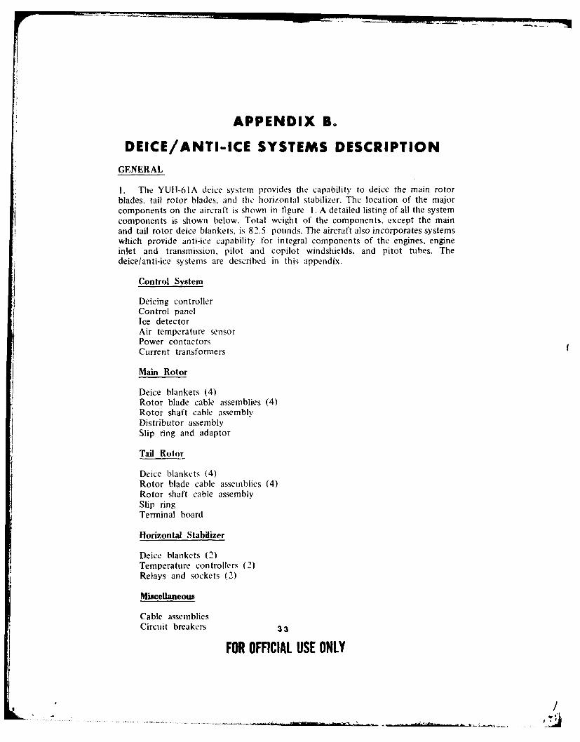
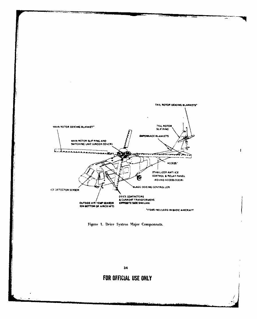
I. The YUH-61A deice system provides the capability to deice the main rotorblades, tail rotor blades, and the horizontal stabilizer. The location of the majorcomponents on the aircraft is shown in figure 1. A detailed listing of all the systemcomponents is shown below. Total weight of the components. except the mainand tail rotor deice blankets, is 82.5 pounds. The aircraft also incorporates systemswhich provide anti-ice capability for integral components of the engines, engineinlet and transmission, pilot and copilot windshields, and pitot tubes. Thedeice/anti-ice systems are described in this appendix.
Control System
Deicing controllerControl panelIce detectorAir temperature sensorPower contactorsCurrent transformers
Main Rotor
Deice blankets (4)Rotor blade cable assemblies (4)Rotor shaft cable assemblyDistributor assemblySlip ring and adaptor
Tail Rotor
Deice blankets (4)Rotor blade cable assemblies (4)Rotor shaft cable assemblySlip ringTerminal board
Horizontal Stabilizer
Deice blankets (2)Temperature controllers (2)Relays and sockets (2)
Miscellaneous
Cable assembliesCircuit breakers 33
FOR OFFICIAL USE ONLY
TAIL ROTOR OEICI G BLANKETS'
MAINa ROTOR DEICING BLANKET' TAIL ROTOR
MA11 MOO SLIPLII' RING ANO
CONTROL & RELAY PANEL
fBfJlND ACCESS DOORk
SLADE DEICING CONTROL LERICE DETECTOR SENSOR ""
~DEICE CONTACTOR S
A CURRENT TRANSFORMERS
OUTSIOf AIR TEMP SENSOR IOPQWI IE SCE SIMILAR$ODN DOM OF AIRCA I
ITEMIS INCLUODO IN "ASIC AIRCRAFT
Fignre 1. Deice System Major Components.
34
FOR OFFICIAL USE ONLY
DEICE SYSTEM
Main Rotor Blades
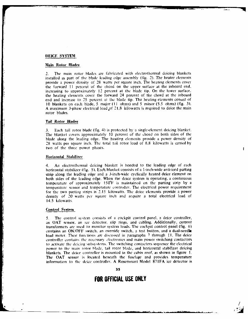
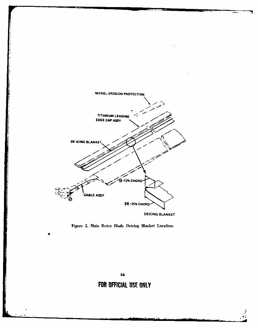
2. The main rotor blades are fabricated with electrothermal deicing blanketsinstalled as part of the blade leading edge assembly (fig. 2). The heater elementsprovide a power density of 28 watts per square inch. The heating elements coverthe forward II percent of the chord on the upper surface at the inboard end,increasing to approximately 12 percent at the blade tip. On the lower surface.the heating elements cover the forward 24 percent of the chord at the inboardend and increase to 25 percent at the blade tip. The heating elements consist of10 blankets on each blade, 5 major (II ohms) and 5 minor (5.5 ohms) (fig. 3).A maximum 3-phase electrical load ,of 21.8 kilowatts is required to deice the mainrotor blades.Tail Rotor Blades
3. Each tail rotor blade (fig. 4) is protected by a single-element deicing blanket.The blanket covers approximately 10 percent of the chord on both sides of theblade along the leading edge. The heating elements provide a power density of28 watts per square inch. The total tail rotor load of 8.8 kilowatts is crried bytwo of the three power phases.
Horizontal Stabilizer
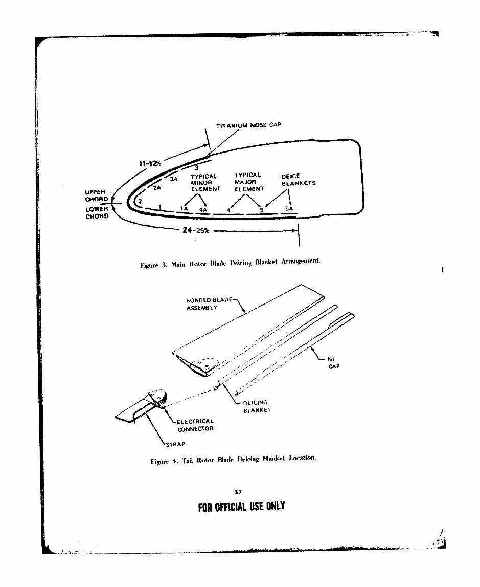
4. An electrothermal deicing blanket is bonded to the leading edge of eachhorizontal stabilizer (fig. 5). Each blanket consists of a I-inch-wide anti-iced partingstrip along the leading edge and a 3-inch-wide cyclically heated deice element onboth sides of the leading edge. When the deice system is operating, a continuoustemperature of approximately 150F is maintained on the parting strip by atemperature sensor and temperature controller. The electrical power requirementfor the two parting strips is 2.15 kilowatts. The deice elements provide a powerdensity of 20 watts per square inch and require a total electrical load of14.5 kilowatts.
Control System
5. The control system consists of a cockpit control panel, a deice controller,an OAT sensor, an ice detector, slip rings. and cabling. Additionally, currenttransformers are used to monitor system loads. The cockpit control panel (fig. 6)contains an ON/OFF switch, an override switch, a test button, and a dual-needleload meter. Their functions are discussed in paragraphs 7 through i1. Tile deicecontroller contains the necessary clectronics and main power switching contactorsto activate tile lcicilig subsystems. The switching contactors sequence tile electricalpower to the main rotor blade, tail rotor blade, and horizontal stabilizer deicingblankets. The deice controller is mounted in the cabin roof, as shown in figure 1.The OAT snsor is located beneath the fuselage and provides temperatureinformation to tile deice controller. A Rosemount Model 871FA ice detector is
35
FOR OFFICIAL USE ONLY
/
NICKEL EROSION PROTECTION
TITANIUM LEADING~EDGE CAP ASSy
DE-ICING BLANKET
C N -12% CHORD
CABLE ASSY
Z-25% CH4ORD
DEICING BLANKET
Figure 2. Main Rotor Blade Deicing Blanket Location.
36
FOR OFFICIAL USE ONLY
TITANIUM NOSE CAP
BIONDE BLARDLANET
UPE ELEEN ELMN
LOWE /N ZAN
CHOCT .....L
ACA
Figiire 4. 'rail Rotor Blade lDeicirtg Blanket Location.
37
HOA OFFCIAL USE ONLY
OEICEO AREAS
(ANTI-ICED AREAOON4IANT 160"PI
NOR SPnNYAL STAGOIZtE1
Of ICING GLANOKET
Figure 5. hforizontal Stabilizer Deicing Blanket Location.
0 DEICE TIST 0
OFF 125 125 STB10i LA ROTOR
-75 75- OFF-50 % s0o-
Li-2 o25 y
w ON1)OVERRIDE OEMNI GIN 2()
Figure 6. Cockpit Control Panel.
3B
FOR OFFICIAL USE ONLY
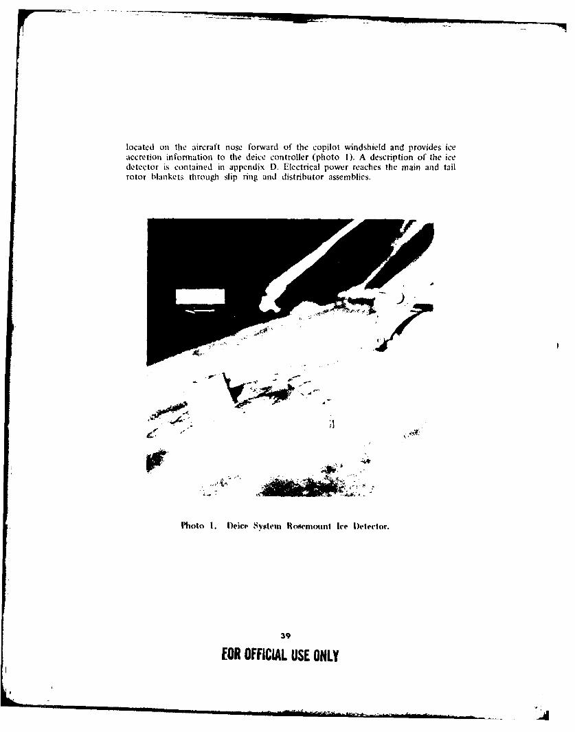
located on the aircraft nose forward of the copilot windshield and provides iceaccretion information to the deice controller (photo 1). A description of the icedetector is contained in appendix D. Electrical power reaches the main and tailrotor blankets throughi slip ring and distributor assemblies.
Photo 1. D)eice System Rosemtount Ice D~etector.
39
EOR OFFICIAL USE ONLY

IvI oleo--
ollec11. O 1111
Ye- $.#I4
Figure 7. Deicing System Schematic.
System Operation
6. A system schematic is shown in figure 7. The sequence of a typical deicecycle is shown in figure 8. Generally, the system allows ice accretion and thendeices, based on OAT and ice accretion rate.
7. The ROTOR/STAB switch on the cockpit control panel is placed ON toenergize the deice system. This switches all the normal aircraft electrical loads tothe No. I generator and energizes the ice detector and the horizontal stabilizerparting strips. All the electrical power necessary to operate the deice system issupplied by the No. 2 generator.
8. In the event of failure of the No. 2 generator, the OVERRIDE switch isplaced in the ON position and the No. I generator is used to furnish the requiredelectrical power for deice system operation. If this occurs, nonessential electricalrequirements may be curtailed to remain within single generator output capacity.The ice detector senses the presence of ice by monitoring the natural frequencyof a magnetostrictive element. The deice system ice detector is similar in operationto the special Rosemount instrumentation discussed in paragraph 1 I, appendix D.Basically, as ice is accreted on the detectors, the natural frequency lowers. Whenthe frequency is lower than a preset limit (0.020 inch of ice), a discrete signafis sent to the deice controller unit. The accreted ice is then heat purged fromthe detector and the controller stores an ice count of I. Ice is again allowed toaccrete on the detector until a second ice pulse occurs. Upon receipt of the secondpulse, the controller unit sends a power pulse to the four tail rotor blade heating
40
FOR OFFICIAL USE ONLY
/-~ I *
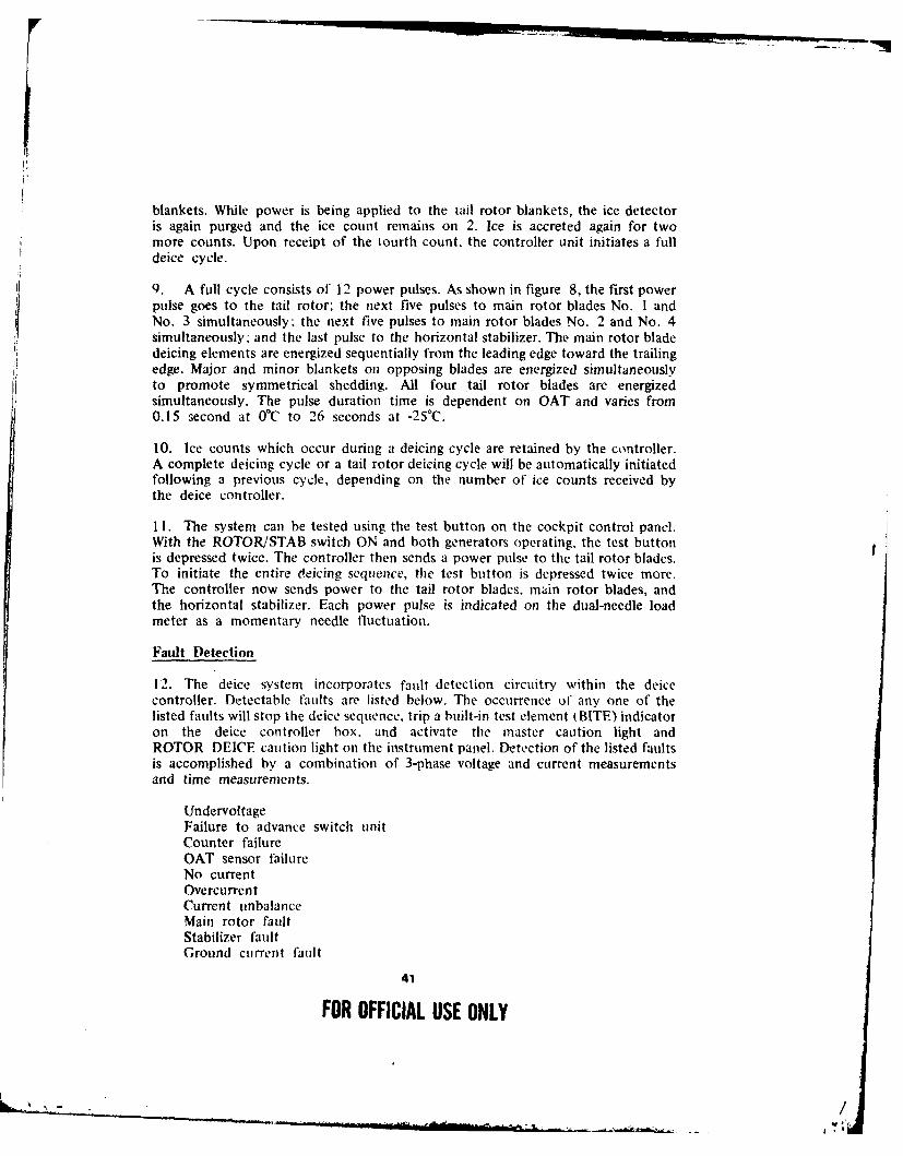
blankets. While power is being applied to the tail rotor blankets, the ice detectoris again purged and the ice count remains on 2. Ice is accreted again for twomore counts. Upon receipt of the lourth count, the controller unit initiates a filldeice cycle.
9. A full cycle consists of 12 power pulses. As shown in figure 8, the first powerpulse goes to the tail rotor; the next five pulses to main rotor blades No. I andNo. 3 simultaneously; the next five pulses to main rotor blades No. 2 and No. 4simultaneously: and the last pulse to the horizontal stabilizer. The main rotor bladedeicing elements are energized sequentially from the leading edge toward the trailing
edge. Major and minor blankets on opposing blades are energized simultaneouslyto promote symmetrical shedding. All four tail rotor blades are energizedsimultaneously. The pulse duration time is dependent on OAT and varies from0.15 second at 0°C to 26 seconds at -25'C.
10. Ice counts which occur during a deicing cycle are retained by the controller.A complete deicing cycle or a tail rotor deicing cycle will be automatically initiatedfollowing a previous cycle, depending on the number of ice counts received bythe deice controller.
11. The system can be tested using the test button on the cockpit control panel.With the ROTOR/STAB switch ON and both generators operating, the test buttonis depressed twice. The controller then sends a power pulse to the tail rotor blades.To initiate the entire deicing sequence, the test button is depressed twice more.The controller now sends power to the tail rotor blades, main rotor blades, andthe horizontal stabilizer. Each power pulse is indicated on the dual-needle loadmeter as a momentary needle fluctuation.
Fault Detection
12. The deice system incorporates fault detection circuitry within the deicecontroller. Detectable faults are listed below. The occurrence of any one of thelisted faults will stop the deice sequence, trip a built-in test element (BITE) indicatoron the deice controller box, and activate the master caution light andROTOR DEICE caution light on the instrument panel. Detection of the listed faultsis accomplished by a combination of 3-phase voltage and current measurementsand time measurements.
UndervoltageFailure to advance switch unitCounter failureOAT sensor failureNo currentOvercurrentCurrent unbalanceMain rotor faultStabilizer fauiltGround current fault
41
FOR OFFICIAL USE ONLY
..... __ __ __ __ _ *, /
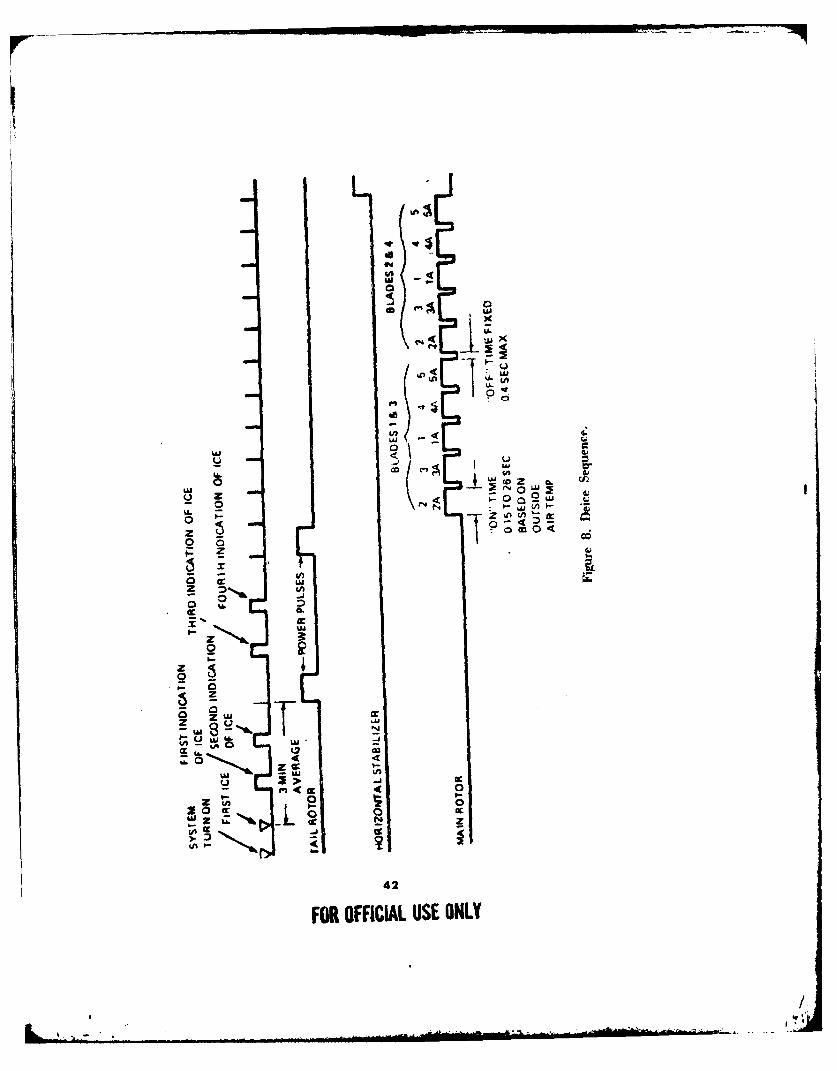
us
00
0
0
00
#-- T
10 0
42
FOR OFFICIAL USE ONLY

blankets. While power is being applied to the tail rotor blankets, the ice detectoris again purged and the ice count remains on 2. Ice is accreted again for twomore counts. Upon receipt of the fourth count, the controller unit initiates a fulldeice cycle.
9. A full cycle consists of 12 power pulses. As shown in figure 8, the first powerpulse goes to the tail rotor: the next five pulses to main rotor blades No. 1 andNo. 3 simultaneously: the next five pulses to main rotor blades No. 2 and No. 4simultaneously. and the last pulse to the horizontal stabilizer. The main rotor bladedeicing elements are energized sequentially from the leading edge toward the trailingedge. Major and minor blankets on opposing blades are energized simultaneouslyto promote symmetrical shedding. All four tail rotor blades are energizedsimultaneously. The pulse duration time is dependent on OAT and varies from0.15 second at 0°C to 26 seconds at -25CC.
10. Ice counts which occur during a deicing cycle are retained by the controller.A complete deicing cycle or a tail rotor deicing cycle will be automatically initiatedfollowing a previous cycle, depending on the number of ice counts received bythe deice controller.
11. The system can be tested using the test button on the cockpit control panel.With the ROTOR/STAB switch ON and both generators operating, the test buttonis depressed twice. The controller then sends a power pulse to the tail rotor blades.To initiate the entire deicing sequence, the test button is depressed twice more.The controller now sends power to the tail rotor blades, main rotor blades, andthe horizontal stabilizer. Each power pulse is indicated on the dual-needle loadmeter as a momentary needle fluctuation.
Fatdt Detection
12. The deice system incorporates fault detection circuitry within the deicecontroller. Detectable faults are listed below. The occurrence of any one of thelisted faults will stop the deice sequence, trip a built-in test element (BITE) indicatoron the deice controller box. and activate the master caution light andROTOR DEICE caution light on the instrument panel. Detection of the listed faultsis accomplished by a combination of 3-phase voltage and current measurementsand time measurements.
UndervoltageFailure to advance switch unitCounter failureOAT sensor failureNo currentOvercurren tCurrent unbalanceMain rotor faultStabilizer faultGround current fault
41
FOR OFFICIAL USE ONLY
/
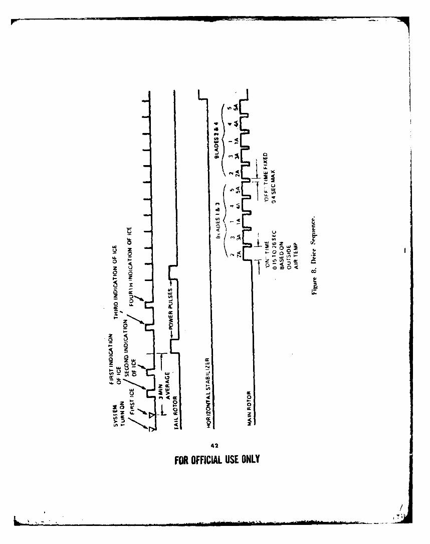
*Is3t4L
wx
4a-j
L i
0 ?-~- CV)
An~O
2 _;
4 attoE
-d a
42
FOR OFFICIAL USE ONLY
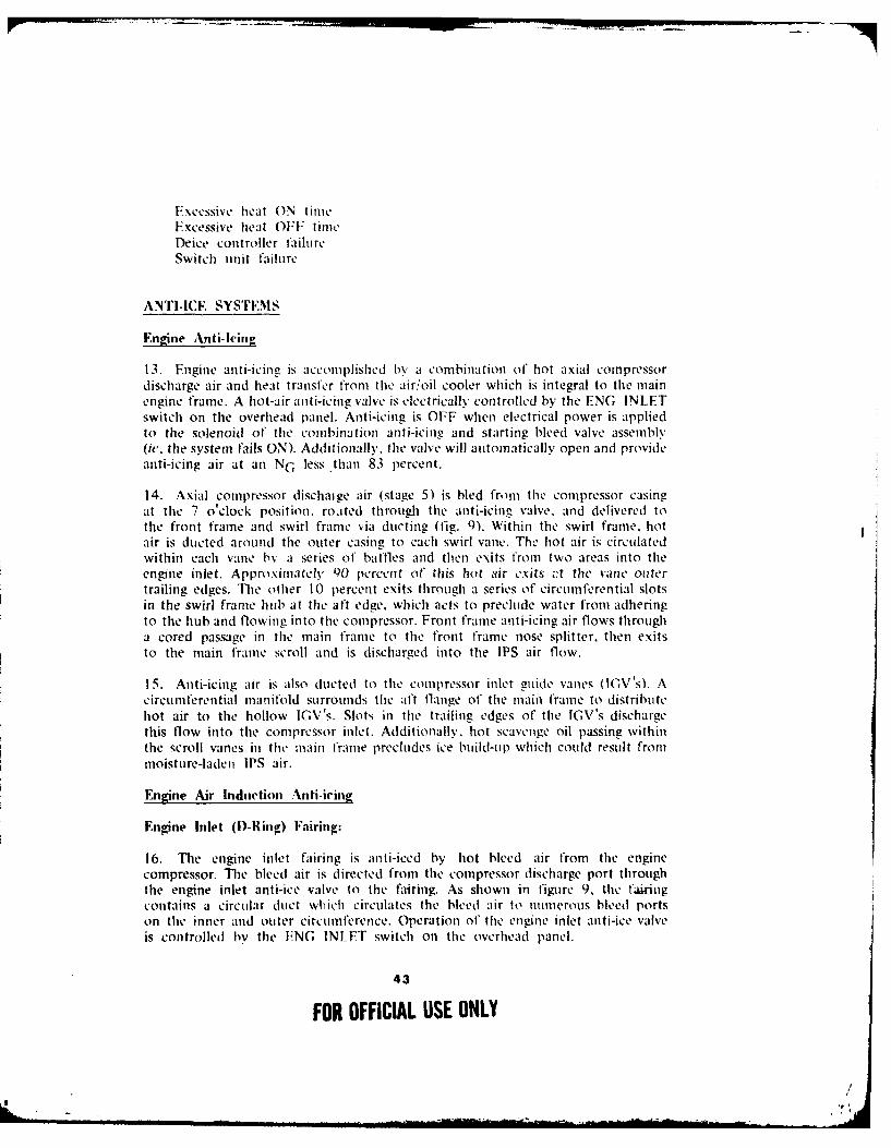
Excessive heat ON tieExcessive heat OFF time
Deice controller failureSwitch unit failure
ANTI-ICE SYSTEMS
Engine Anti-heing
13. Engine anti-icing is accomplished by a combination of hot axial compressordischarge air and heat transfer from the air/oil cooler which is integral to the mainengine frame. A hot-air anti-icing valve is electrically controlled by the ENG INLETswitch on the overhead panel. Anti-icing is OFF when electrical power is appliedto the solenoid of the combination anti-icing and starting bleed valve assembly(i,. the system fails ON). Additionally. the valve will automatically open and provideanti-icing air at an NG less than 83 percent.
14. Axial compressor dischaige air (stage 5) is bled fromr the compressor casingat the 7 o'clock position. roated through the anti-icing valve, and delivered tothe front frame and swirl frame via ducting (fig. 9). Within the swirl frame, hotair is ducted around the outer casing to each swirl vane. The hot air is circulatedwithin each vane by a series of batfles and then exits from two areas into theengne inlet. Approximately 90 percent of this hot Air exits .t the vane outertrailing edges. The other 10 percent exits through a series of circumferential slotsin the swirl frame hub at the aft edge, which acts to preclude water from adheringto the hub and flowing into the compressor. Front frame anti-icing air flows througha cored passage in the main frame to the front frame nose splitter, then exitsto the main frame scroll and is discharged into the IPS air flow.
15. Anti-icing air is also ducted to the compressor inlet guide vanes IV s). Acircumferential nanifold surrounds tile aft flange of the main frame to distributehot air to the hollow IGV's. Slots in the trailing edges of the IGV's dischargethis flow into the compressor inlet. Additionally,. hot scavenge oil passing withinthe scroll vanes in the main frame precludes ice build-up which could result frommoisture-laden IPS air.
Engine Air Indnction Anti-icing
Engine Inlet (D-Ring) Fairing:
16. The engine inlet fairing is anti-iced by hot bleed air from the enginecompressor. The bleed air is directed from the compressor discharge port throughthe engine inlet anti-ice valve to the fairing. As shown in figure 9, the fainngcontains a circular duct which circulates the bleed air to numerous bleed portson the inner and outer circumference. Operation of the engine inlet anti-ice valveis controlled by the ENG INLET switch on the overhead panel.
43
FOR OFFICIAL USE ONLY

000
.........
FOR OFICIL US ONL
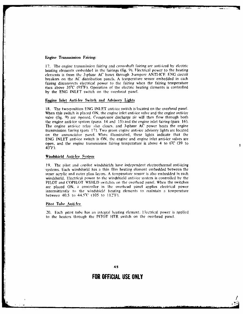
Engine Transmission Fairing:
17. The engine transmission fairing and cross-shaft fairing are anti-iced by electricheating elements embedded in the fairings (fig. 9). Electrical power to the heating
elements is from the 3-phase AC buses through 3-ampere ANTI-ICE ENG circuitbreakers on the AC distribution panels. A temperature sensor embedded in each
~fairing disconnects electrical power to the fairing when the fairing temperature
rises above 35°C (95F). Operation of the electric heating elements is controlledby the ENG INLET switch on the overhead panel.
~Engine Inlet Anti-lee Switch and Advisory Lights
18. The two-position ENG INLET anti-ice switch is located on the overhead panel.When this switch is placed ON, the engine inlet anti-ice valve and the engine anti-icevalve (fig. 9) are opened. Compressor discharge air will then tiow through both
the engine anti-ice system (paras 14 and 15) and the engine inlet fairing (para 16).The engine anti-ice relay also closes, and 3-phase AC power heats the enginetransmission fairing (para 17). Two green engine anti-ice advisory lights are located
on the annunciator panel. When illuminated, these lights indicate that theENG INLET anti-ice switch is ON. the engine and engine inlet anti-ice valves areopen, and the engine transmission fairing temperature is above 4 to 6°C (39 to
430F).
Windshield Anti-Ice System
19. The pilot and copilot windshields have independent electrothermal anti-icing
systems. Each windshield has a thin film heating element embedded between theinner acrylic and outer glass layers. A temperature sensor is also embedded in eachwindshield. Electrical power to the windshield anti-ice system is controlled by the
PILOT and COPILOT WSHLD switches oil the overhead panel. When the switchesare placed ON. a controller in the overhead panel applies electrical powerintermittently to the windshield heating elements to maintain a temperature
between 40.5 to 44.5'C (105 to 112'F).
Pitot Tube Anti-Ice
20. Each pitot tube has an integral heating element. Electrical power is appliedto the heaters through the PITOT HTR switch on the overhead panel.
45
FOR OFFICIAL USE ONLY
/*
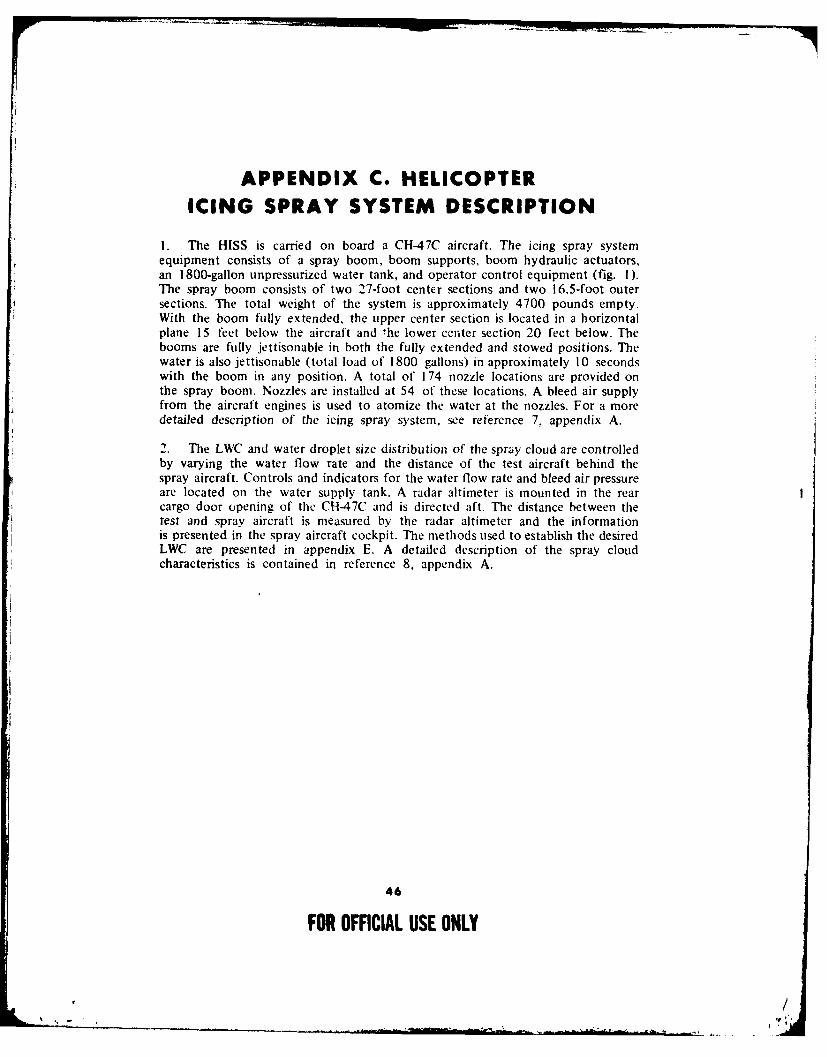
APPENDIX C. HELICOPTERICING SPRAY SYSTEM DESCRIPTION
I. The HISS is carried on board a CH-47C aircraft. The icing spray systemequipment consists of a spray boom, boom supports, boom hydraulic actuators,an 1800-gallon unpressurized water tank, and operator control equipment (fig. I).The spray boom consists of two 27-foot center sections and two 16.5-foot outersections. The total weight of the system is approximately 4700 pounds empty.With the boom fully extended, the upper center section is located in a horizontalplane 15 feet below the aircraft and the lower center section 20 feet below. Thebooms are fully jettisonable in both the fully extended and stowed positions. Thewater is also jettisonable (total load of 1800 gallons) in approximately 10 secondswith the boom in any position. A total of 174 nozzle locations are provided onthe spray boom. Nozzles are installed at 54 of these locations. A bleed air supplyfrom the aircraft engines is used to atomize the water at the nozzles. For a moredetailed description of the icing spray system, see reference 7, appendix A.
2. The LWC and water droplet size distribution of the spray cloud are controlledby varying the water flow rate and the distance of the test aircraft behind thespray aircraft. Controls and indicators for the water flow rate and bleed air pressureare located on the water supply tank. A radar altimeter is mounted in the rearcargo door opening of the CH-47C and is directed aft. The distance between thetest and spray aircraft is measured by the radar altimeter and the informationis presented in the spray aircraft cockpit. The methods used to establish the desiredLWC are presented in appendix E. A detailed description of the spray cloudcharacteristics is contained in reference 8, appendix A.
46
FOR OFFICIAL USE ONLY
!/
, ,l
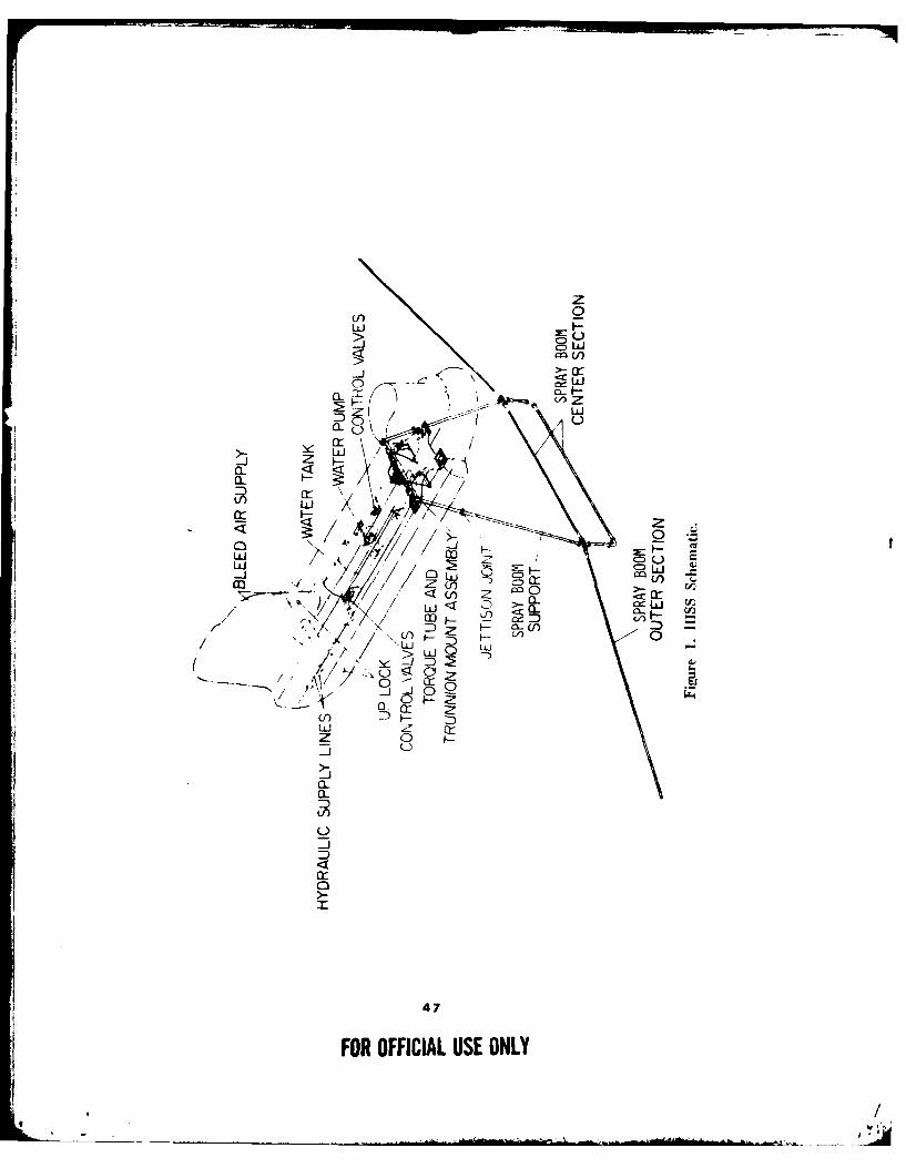
cLLL
0: ~LJ
z i.-
-J a-
( -
CL!
<~ >jC13D
a - - F
-- J
0 F
47
FOR OFFICIAL USE ONLY
tl/

APPENDIX D.
INSTRUMENTATION AND SPECIAL EQUIPMENTINSTRUMENTATION
1. In addition to, or instead of, standard aircraft instruments, sensitive calibratedinstrumentation was installed aboard the test aircraft and maintained by thecontractor. Data were recorded from the cockpit instrumentation and speciallyinstalled instrumentation system. Data were recorded on flight data cards andmagnetic tape (PCM and FM). Selected parameters were observed real time viaair-to-ground telemetry. Flight crew comments were recorded on a portable taperecorder.2. The sensitive instrumentation, calibrated ship's system instrumentation, and
related special equipment installed are listed below.
Pilot Station
Data recorder switchEvent switch
Pilot Panel
AirspeedAltitude (ship's system)Altitude (radar)Rotor speed (digital)Rotor speed (ship's system)Engine torque (both engines)Engine turbine gas temperature (both engines)Engine gas generator speed (both engines)Control position:
LongitudinalLateralDirectionalCollectiveTail rotor slider
Horizontal tail positionCenter-of-gravity normal acceleration
Copilot/Enineer Station
Instrumentation controls and lightsOn-board camera controls and lightsData recorder switchEvent switchVisual ice accretion probe
48
FOR OFFICIAL USE ONLY
, /
Copilot/Engineer Panel
AirspeedAltitudeRotor speedEngine torque (both engines)Free air temperatureMain rotor blade temperatureFuel used (both engines)Deice system ice detector signal lightRosemount icing rateNormalair-Garrett icing conditionIntegral particle separator duct differential
pressure (both engines)Time code displayRun number
Diital (PCM) Data Parameters
AirspeedAltitude (ship's system)Altitude (radar)Rate of climbFree air temperatureRotor speedEngine gas generator speed (both engines)Engine power turbine speed (both engines)Engine output shaft torque (both engines)Engine turbine gas temperature (both engines)Fuel flow (both engines)Fuel used (both engines)Integral particle separator duct diftereitial
pressure (both engines)Control position:
LongitudinalLateralDirectionalCollectiveEngine condition lever (both engines)
Tail rotor sliderYaw compensator actuator positionHorizontal tail positionMain rotor shaft bending
49
FOR OFFICIAL USE ONLY
, /
Main rotor and tail rotor cameras:Correlation pulseRun commandFailure signalOut of phase signalFilm used
Engine transmission nose fairing temperature(both engines)
Engine transmission fairing fold temperature(both engines)
Main rotor blade blanket temperatureGenerator No. 1:
FrequencyVoltage (A, B, and C phase)Current (A, B, and C phase)
Deice/anti-ice systems electrical parameters:Main rotor voltage (A phase)Main rotor current (A phase)Tail rotor voltage (A-B and B-C phase)Tail rotor current (A aid C phase)Horizontal stabilizer voltage (left and right side)Horizontal stabilizer current (left and right side)Engine transmission fairing voltage (No. I engine)Engine transmission fairing current (No. I engine)Windshield voltage (single-phase)Windshield current (single-phase)
Rosemount icing rate (instrumentation system)Rosemount icing rate (ship's system)Normalair-Garrett icing conditionPitch attitudeRoll attitudeTime codeRun numberEvent marker
Analog (FM) Data Parameters
Main rotor blade camera correlationEvent markerVoice
5O
FOR OFFICIAL USE ONLY
.!- ~
Vibration (accelerometers):Pilot seat (vertical, lateral, and longitudinal)Copilot seat (vertical, lateral, and longitudinal)Instrument panel (right side vertical and lateral)Instrument panel (left side vertical)Center of gravity (vertical, lateral, and longitudinal)Main rotor transmission (vertical, lateral, and longitudinal)Tail rotor transmission (vertical, lateral, and longitudinal)
3. In addition to standard aircraft instruments, sensitive calibratedinstrumentation was installed aboard the CH-47C spray aircraft. Thisinstrumentation was used to establish the desired test conditions during the icingflights and is listed below.
AirspeedAltitudeFree air temperatureDew pointWater flow rateBleed air pressureRadar distance (separation between test and spray aircraft)
SPECIAL EQUIPMENT
Camera Svstems
4. Two 16mm high-speed, hand-held motion pictre cameras were used todocument ice accretion characteristics of the test aircraft. One camera was locatedon board the CH-47C spray aircraft and was used while the test aircraft was inthe spray cloud. The other camera was located on board the chase aircraft andwas used to document the test aircraft both in the spray cloud and after exitfrom the cloud, Additionally, 35mm slide and black and white still cameras wereused for documentation both in the air and on the ground following each icingflight.
5. In addition to the chase and HISS high-speed photography, documentationof main and tail rotor condition was achieved using nonrotating 16mm high-speedcameras mounted on board the test aircraft. The main rotor blade camera waslocated in the cargo compartment and viewed the lower surface of the main rotorblades through the right-hand forward cargo door window (photo I). A secondcamera, mounted on the left side of the tail boom at the fold hinge, was usedto photograph the leading edge of the tail rotor blades and a section of the left-handhorizontal stabilizer (photo 2). A camera control panel was mounted just aft ofthe cockpit center console with one master power switch and a run switch(ON-OFF) for each camera. With the master power switch ON, power was suppliedto the camera motors, electronics, and heaters.
51
FOR OFFICIAL USE ONLY
-.-
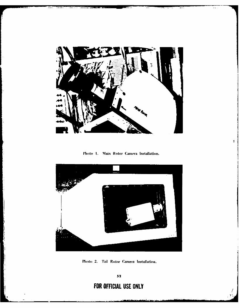
PMoto 1. Main Rotor Camera Installation.
Mhoto 2. Tail Rotor Camera Installation.
52
FOR OFFICIAL USE ONLY

6. The cameras, manufactured by Photo-Sonic Inc, were 16mm Model IPLcameras with phase lock kits and 1200-foot film magazines, Shutter speeds of 16 to500 frames per second could be selected. The cameras were synchronized tophotograph the blades at fixed aircraft azimuths. Synchronization was achievedby triggering the camera shutter through the phase lock kit with a multiplexedand phase compensated I/rev signal. The main rotor camera had the capabilityof photographing blades at four or eight frames per rotor revolution. Shutter speedsup to 1 / 1800 second were used at four frames per revolution. The tail rotor camerahad the capability for synchronization at one or two frames per tail rotor revolution.Design characteristics are listed below.
Temperature -65 to +160FVibration 5 to 17 Hz at 0.7-inch
double amplitude17 to 4000 Hz at 10g
Acceleration 2 5g (three major axes)
7. The main rotor blade camera was mounted on a square cross-section beamattached to the vertical aircraft support structure at FS 129 and 201 on the rightside of the cabin interior. The span of the beam was the span of the cargo dooropening. A Winter Engineering Company Model 1610B mount with two degreesof adjustment (pitch and yaw) and quick-disconnect features was attached to thebeam for camera mounting. A 5.3rm lens was used on the main rotor camera,which provided a field of view from inboard of the pendulum vibration absorbersto the blade tips.
8. The tail rotor camera was mounted in a water-tight box attached to theleft-hand side of the tail boom at the tail fold hinges. A secondary supportattachment was made at the first vertical aircraft support forward of the fold hinge.The camera was mounted inside the box on a Winter Engineering Company mount.A heated window provided by Pittsburg Plate Glass was used to ensure a clearviewing surface.
Icing Detectors
General:
9. Two icing detectors were installed on the test aircraft to correlate the icingseverity levels experienced by the test aircraft with the LWC established by theCH-47C spray aircraft. A third ice detector was installed as an integral componentof the aircraft deice system (para 5, app B). A visual ice accretion probe wasalso installed on the test aircraft to observe icing rates. These items are describedin the following paragraphs.
53
FOR OFFICIAL USE ONLY
j ' (/.
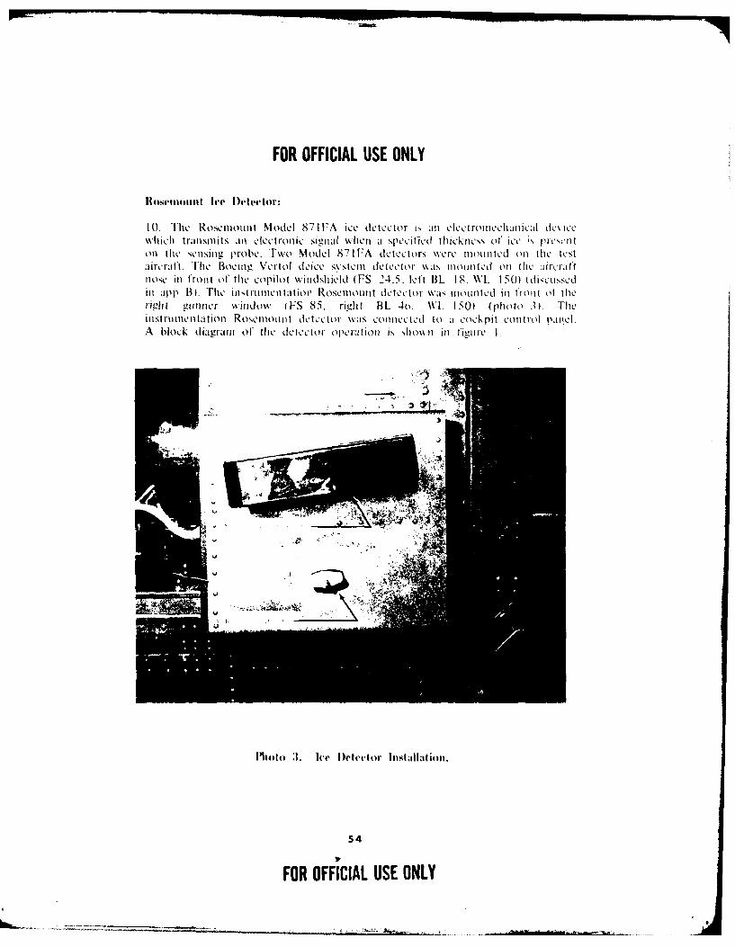
FOR OFFICIAL USE ONLY
Rosentmiit Ice D~etector:
1 0. The Rosemiont Model 87 lEA ice detc ctor is anl elct romncchan ical dce cwhich transmits anl electron ic sigl'A 1When a speciftied thick ness of ice ;', pr1,Cnon [lt: sensins, probe. Two Model 871F A detectors were monn1tcd Onl file ICStaircraft. The Bo0CMIn VCrtol dCicQ S\SWtcm d tCctot' waZs mon n tde~ onil aI Arcra ftnose inl front of' thc copilot windshield (WS 24.5, lcft 13L 18. \\'I 150) I di';~S'Cnsdin app B). Thc inst rumentatlion Roscmonn t11 dctCCior- \VI mon n tlcd inl front oft herigh Itgnncir wkindow ( FS 85. righ t 13L 40. WL 1 50) (photo .30. Theinst ru mentatlion Rosemon t dctCt icc Cor wasco Cc to a cockpit control pan.lA block d iagrain of the detctfc or opera tion is shown in figuire I.
544
FOR OFFICIAL USE ONLY
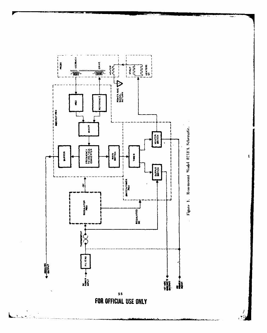
I I
F-- ilLC_
wz,
:L I
I . .. --
ii I
Iccc
atS
L --------- --- -ONLY-4
Ig -
!FS-- - - - - - - - - . . . .. . . . . . . . . . . . .
9"-- ~ -
FO OFCA UEOL

I I. The operation of the two detectors is identical. The sensing element of theice detector is an axially vibrating probe whose natural frequency changes withice accumulation. Probe v' 'ition is achieved with the magnetostrictive oscillator(MSO). The reference os .... ator signal is summed with the signal from the MSOto produce a difference frequency (the output of the mixer). Thefrequency-to-voltage converter changes the difference frequency to a voltage, andwhen this voltage reti,'hes a preset value corresponding to the accumulation of0.020 inch (0.5mm) of ice, an output signal is provided to the timer. The timerinitiates the probe heating cycle which purges the probe of the accumulated ice.A constant-voltage output signal is provided which the Boeing Vertol deice systemuses to trigger the control unit (para 9, app B). The signal from the Rosemountdetector illuminates a red light on the cockpit control panel and is recorded onmagnetic tape. After the probe heating cycle is completed the probe is ready toaccrete ice and th,, sequence is repeated.
12. The frequency-to-voltage converter of the MSO also provides a variable-voltageanalog output corresponding to ice thickness. The Rosemount detector signal wasdifferentiated and displayed in the cockpit as an icing severity on the RosemountModel 51 2P icing rate meter 'photo 4). The Boeing Vertol detector analog outputwas recorded on magnetic tape for data analysis purposes.
Photo 4. Special Equpipment (Rosemouil) Ice l)eiertor Indicalor Panel.
56
FOR OFFICIAL USE ONLY
, /
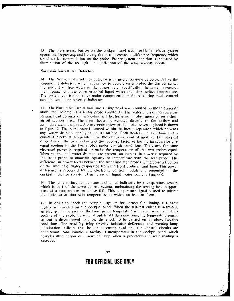
13. The press-to-test button ol the cockpit panel was provided to check systemoperation. Depressing and holding the button creates a differnnce frequency whichsimulates ice accuniula-ion on the probe. Proper system operation is indicated byillumination of the rec light and dellection of the icing stverity needle.
Nornalair-Garrett Ice Detector:
14. The Normalair-Garrett ice detector is an inferential-type detector. Unlike theRosemount detector, which allows ice to accrete on a probe. the Garrett sensesthe amount of free water in the atmosphere. Specifically, the system measuresthe impingement rate of supercooled liquid water and icing surface temperature.
The system consists of three major components: moisture sensing head, controlmodule, and icing severity indicator.
15. The Normalair-Garrett moisture sensing head was mounted on the test aircraftabove the Rosemount detector probe (photo 3). The water and skin temperatureensing head consists of two cylindrical heater/sensor probes mounted on a short
airfoil section mast. The front heater is exposed directly to the airflow andimpinging water droplets. A cross-section view of the moisture sensine head is shownin figure 2. The rear heater is housed within the inertia separator, which preventsany water droplets impinging on its surface. Both heaters are maintained at aconstant electrical temperature by the electronic control module. The physicalproperties of the two probes and tile recovery factor of the inertia separator giveequal cooling to the two probes under dry air conditions. Therefore. the sameelectrical power is required to make the temperature of the two probes equal.When supercooled water droplets are present, an increase in power is required bythe front probe to maintain equality of temperature with the rear probe. Thedifference in power levels between the front and rear probes is therefore a fractionof the amount of water evaporated from the front probe in unit time. This powerdifference is processed by the electronic control module and presented on thecockpit indicator (photo 5) in terms of liquid water content (ginm3 ).
16. The icing surface teninerature is obtained indirectly by a temperature sensor.which is part of the servo control system, maintaining the sensing head supportmast at a temperature set above OWC. This temperature signal is used to inhibitthe indicator at that skin temperature at which no ice can form.
17. In order to check the complete system for correct functioning, a self-testfacility is provided on the cockpit panel. When the self-test switch is activated,an electrical imbalance of the front probe temperature is created, which simulatescooling of the probe by water droplets. At the same time, the temperature sensorcLit-out is disconnected to allow the check to be carried out in above freezingconditions. The resulting icing severity indicator deflection and warning lampillumination indicate that both the sensing head and the control circuits areoperational. Additionally, a facility is incorporated in the cockpit panel whichprovides illumination ol a warning lamp when a predetermined scale reading isexceeded.
57
FOR OFFICIAL USE ONLY
, /
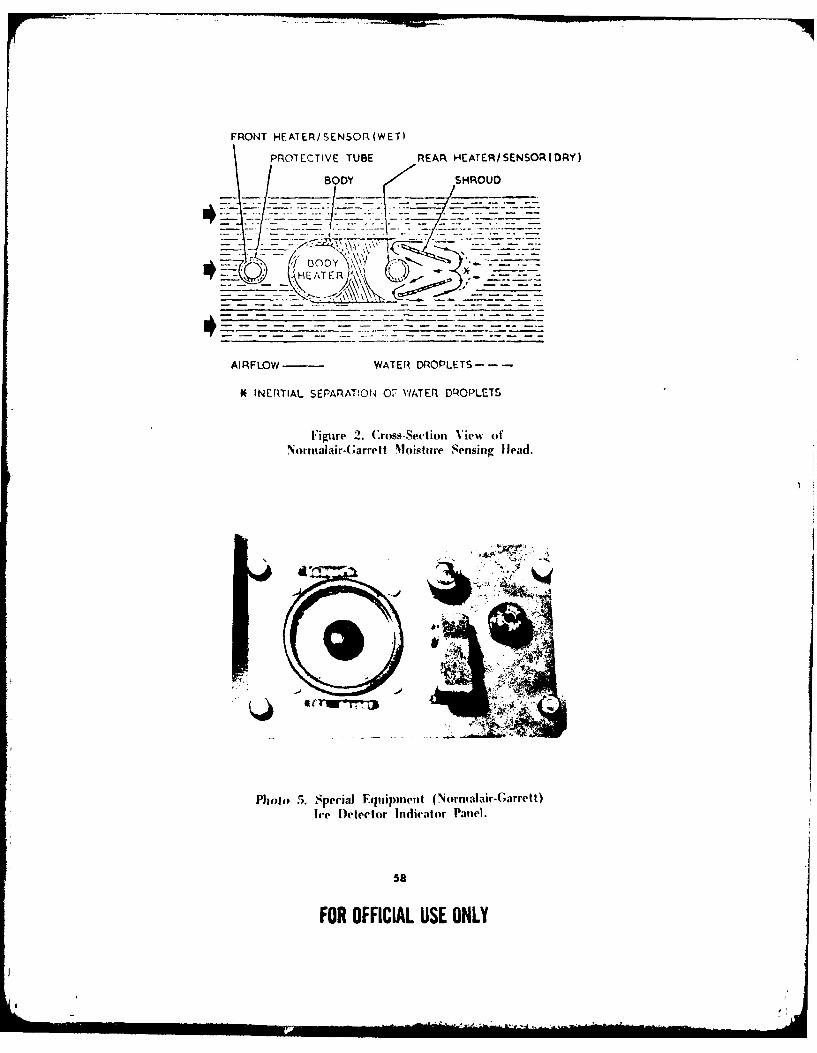
FRONT HEATER/ SENSOR (WET)
PROTECTIVE TUBE REAR HE ATER/ISENSOR (DRY)
BODY SHROUD
13 DDY '- I-______( IHE TER)~\ ___
AIRFLOW WATER DROPLETS - - -
SINERTIAL SEPARAT!ON4 OF WATER DROPLETS
Figure 2. Cross-Section View ofNormtalair-Garre It Moisitire Sensing [lead.
Photo 5. Special Equipmen t (N ornialair-Garrett)Ice D~etector Ind(icator Paviel.
58
FOR OFFICIAL USE ONLY
Visual Ice Accretion Probe:
18. A USAAEFA-designed and fabricated visual ice accretion probe was installedon the copilot door below the window (photo 6). This probe consisted of a3.5-inch-wide airfoil section rigidly mounted on a support shaft. A 1.75-inch-longrod extended forward from the leading edge of the airfoil section and was markedin 1/4-inch increments. Using this probe, the rate and thickness of ice accretionwas observed by the copilot during icing test flights.
Telemetry and Data Reduction System
19. A portable telemetry monitoring (TM) and data reduction system wasfabricated to allow on-site data analysis. It consisted of the following equipment:
Nems-Clarke Type R10376 solid state TM receiverEMR-Schlumberger Model 720 PCM bit synchronizerEMR-Schlumberger Model 2731 PCM frame synchronizerEMR-Schlumberger Model 713 programmable word selectorHewlett-Packard MIodel 5245L electronic counterHewlett-Packard Model 4204A oscillatorTektronix Type 422 oscilloscopeAmpex Model PR 2200 tape transportClevite Model 9200 datum time code translatorGould Model 260 brush recorders (2 each)EMR-Schlumberger Model 4150 proportional bandwidth
subcarrier discrimanator (12 each)EMR-Sclluniberger Model 4150 constant bandwidth
subcarrier discriminator (12 each)Bell ald Ilowc!li dtlagrapli Model 5-134 oscillograph
20. The TM rcccivcr hiad j linc-ol-sighlt range of approximately 20 to 30 nauticalmiles and mon tolrd sicn;sls on a 1435- to 1540-MIlz band. The system convertedthese signals into a i a: timen d ilplav of 12 PCM data channels on the brushrecorders and 6 f:M da ti chanlnels on the oscillograph. The channels monitoredduring a flight were chosen by the project engineer from among any of the channelsbeing recorded by the :jirborne magnetic tape system. The channels displayed couldbe changed at a. time dring tie flight.
21. The package allowed for postfliglt strip-out of the flight tape. Each timethe flight tape wa\ nn throughi the system 12 PCM and 6 FM channels couldbe processed. The electronic counter allowed actual PCM data counts to becompared with pen movements. The flight tape could be reni until all desireddata channels were stripped out. The system allowed for a tape search for a specifiedtime slice and a digilal display of tile data.
59
FOR OFFICIAL USE ONLY
/,. ,,]
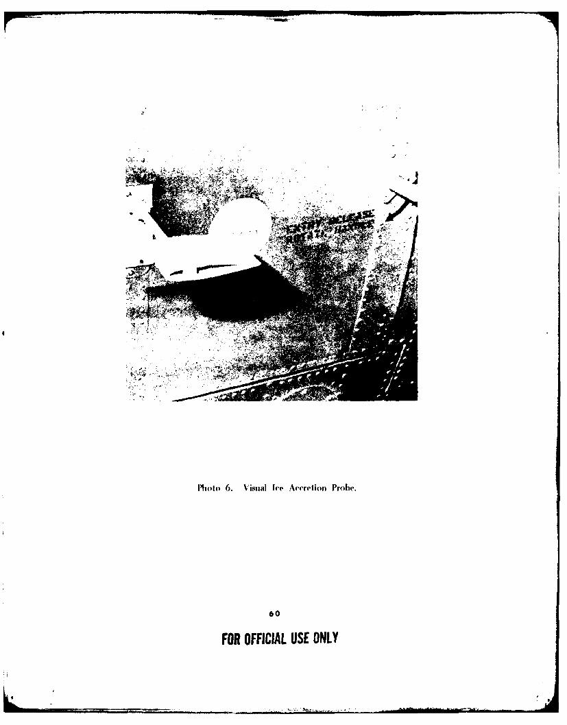
t
PMoto 6. V~isual Ice Acretioni Probe.
60
FOR OFFICIAL USE ONLY
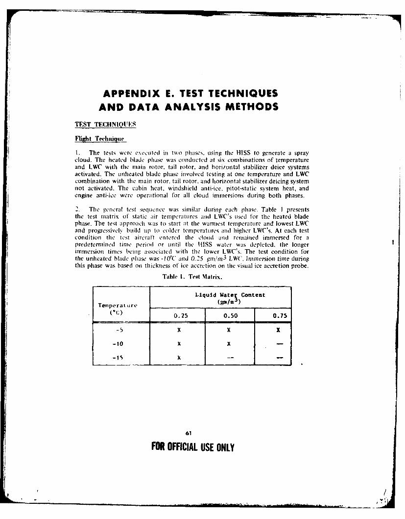
APPENDIX E. TEST TECHNIQUESAND DATA ANALYSIS METHODS
TEST TECHNIQUES
Flight Technique
I. The tests were executed in two phases, using tile HISS to generate a spraycloud. The heated blade phase was conducted at six combinations of temperatureand LWC with the main rotor, tail rotor, and horizontal stabilizer deice systemsactivated. The unheated blade phase involved testing at one temperature and LWCcombination with the main rotor, tail rotor, and horizontal stabilizer deicing systemnot activated. The cabin heat, windshield anti-ice, pitot-static system heat, andengine anti-ice were operational for all cloud immersions during both phases.
2. The general test seqtucnce was similar during each phase. Table I presentsthe test matrix of static air temperatures and LWC's used for the heated bladephase. The test approach was to start at the warmest temperature and lowest LWCand progressively build uip to colder temperatures and higher LWC's. At each testcondition the test aircraft entered the cloud and remained immersed for apredetermined time period or until the HISS water was depleted, the longerimmersion times being associated with the lower LWC's. The test condition forthe unheated blade phase was -I OC and 0.25 gin/O 3 LWC. Immersion time duringthis phase was based on thickness of ice accretion on the visual ice accretion probe.
Table 1. Test Matrix.
Liquid Watel Content
Temperature (m/(C) 0.25 0.50 0.75
-5 X X X
-10 X X -
-15 X -- -
61
FOR OFFICIAL USE ONLY
, /
3. At each test temperature, an engine stall check was conducted. The enginestall check was performed with the engine inlet anti-ice ON and cabin heater ON.From a stable level flight condition, the appropriate ECL was rapidly retardedto START/IDLE. The ECL was then rapidly advanced back to FLT after the enginehad stabilized at idle. Testing continued if there were no stalls. Prior to each cloudimmersion, level flight performance data at 90 KTAS were obtained with thedeice/anti-ice systems ON and OFF.
4. The test aircraft entered the cloud from a position below and 200 feet behindthe HISS. Stand-off distance information was provided by a rear-facing radaraltimeter mounted on the HISS. After the immersion time had elapsed, the aircraftexited the cloud to document the ice accretion and perform specific engineeringtests. Level flight performance data at 90 KTAS were obtained with thedeice/anti-ice systems ON. If ice had accreted on the main or tail rotor blades,an autorotation was conducted to determine rotor speed degradation. The aircraftthen returned to Fort Wainwright for postflight ice accretion measurements.Subsequent flights were flown at either the same temperature and a higher LWCor at a colder temperature and the lowest untested LWC.
5. During the unheated blade phase, no attempt was made by the pilot to inducemain rotor blade shedding. The primary reason was to avoid producing anasymmetrical shed.
HISS Flow Rate Calculation Method
6. Water flow rate of the HISS, to establish the desired icing severity level foreach test flight, was determined using the following technique. The CH-47C sprayaircraft used installed calibrated instruments to establish airspeed, altitude, andstatic air temperature for the desired test condition. The frost point was obtainedby utilizing a Cambridge thennoelectric dew-point hygrometer. The frost point wasthen converted to a dew point using table 2, which was furnished by the instrumentmanufacturer.
Saturation vapor pressure (millibars) for the dew point and static air temperaturewas obtained from table 3.
Relative humidity was then computed using the values obtained from table 2 andequation 1:
PS
Rh = -S x 100 (1)PW
62
FOR OFFICIAL USE ONLY
w /- t'

Table 2. Cambridge Thernoeleetric I)ew PointI yagroneter Conversion Vahlies (Degrees Centigrade).
Frost few Frost Dew Fros t Dew Frost DewPoint Point Point Point Point Point Point Point
-0.0 -0.1 -6.5 -7.3 -13.0 -14.5 -19.5 -21.1-0.5 -0.7 -7.0 -7.9 -13.5 -15.0 -20.0 -22.2-1.0 -1.2 -7.5 -8.4 -14.0 -15.6 -20.5 -22.8-1.5 -1.8 -8.0 -9.0 -14.5 -16.2 -21.0 -23.3-?.0 -2.3 -8.5 -9.5 -15.0 -16.7 -21.5 -23.9-2.5 -2.9 -9.0 -10.1 -15.5 -17.3 -22.0 -24.5-3.0 -3.4 -9.5 -10.6 -16.0 -17.8 -22.5 -25.0-3.5 -4.0 -10.0 -11.2 -16.5 -18.4 -23.0 -25.6-4.0 -4.5 -10.5 -11.7 -17.0 -18.9 -23.5 -26.1-4.5 -5.1 -11.0 -12.3 -17.5 -19.5 -24.0 -26.7-5.0 -5.6 -11.5 -12.8 -18.0 -20.0 -24.5 -27.2-5.5 -6.2 -12.0 -13.4 -18.5 -20.6 -25.0 -27.8-6.0 -6.7 -12.5 -13.9 -19.0 -21.1 -25.5 -28.3
Table 3. Saturation Vapor Pressure Over Water.(Millibars)
o('C~. ' .**... . ., .7 .8
-. ,7k K. '7 1. 7.' 79", ( 1 77 3 0.771 0. 76 1 0.7574 0.7506 J. 7 7 is-0477.88!' l.7,, .7l 1 .1,.8 ). , t1 0.82l1 0.8.1 0.h 71,,
-27 d).97(1.* ,. '*.. , , .t ''.G
*9l9 '.1 l 77 .7 ';2 O.77l74 (I.'4018 7 .9'80 4. ~-2 .. ,, , , ... I." '7. 1. .' ., .M ,1.0,.7I, LA747777 0o974' ) 9'l(7 (7 . 4.1 0..7 1 40", 77-I 7.. .'. I. . I. ., 1 II 0.0.0 9F2 ,
1.'2 7.2141 1 1.
-7,'.Z . '
.,, . ) . I .. *" ; .I1 ,, '' . 797771 .. 1t. . 7. ,,
7'w! , ' . 7 t I ," ' I . . M , . . .1.... 1. ' B. 8 . . .
- 1,, I .". , . . , lS2 . 7 . ,- 1 .J $* -.. "1 7 - j . A- . .. 1. 7 I 1, 2.40712 , ' -
-. 9.. ,,, I . .. *, '., ', ' . - .7t 41,, j gt .
63
FOR OFFICIAL USE ONLY, /.- ,, . . .7 7 '77
63.,
Where:
Rh = Relative humidity (percent)
PVS = Saturation vapor pressure for dew point (millibars)
PW = Saturation vapor pressure for static air temperature(millibars)
7. The decay LWC, which is the spray cloud evaporation rate, was then computedusing equation 2.
LWC = G(100 - Rh) (2)D 4.5G 0
Where:
LWCD = Decay liquid water content (percent/second)
G Thermodynamic function (centimeter2/second)
Rh = Relative humidity (percent) (obtained from equation 1)
= 60 x 10-8 centimeter"/second (constant)
The value for the thermodynamic function G used in equation 2 was obtainedfrom figure 1 using the static air temperature indicated bv the HISS aircraft.Pressure dependence of G is small, so that values for 1000 millibars given infigure I were satisfactory for the test altitudes (ref 13, app A).
The programmed LWC based on the desired test condition was then corrected forevaporation using the decay LWC calculated above and equation 3.
LWCD D (3)
LWCc = - I.68 89VT) (LWCp) + (,1413)
Where:
LWCc = Corrected liquid water content (gm/n 3 )
LWCD Decay liquid water content (percent/second)
64
FOR OFFIC!AL USE ONLY
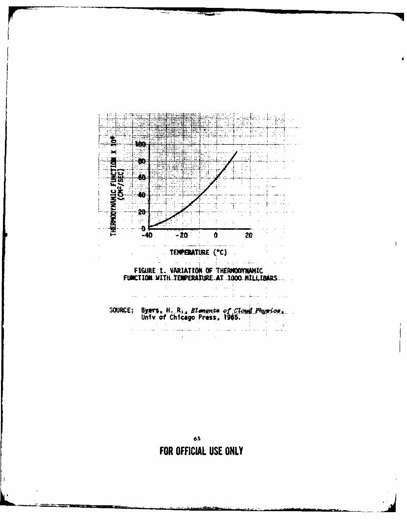
VTT
0ff4
-40. -26-: a 20
TEMPATURE (-Q
FIGUR~E t:. VMRATIOI4 (W THEMMONMIC
FUNCTIOUt WITfLt -EA~UrT IOMMI4MTSRS-
SOMiRE; jym ,--R . g x.n# oZ4lywoUniv of Mko Pressi, 1965.
65
FOR OFFICIAL USE ONLY
D = 200 feet (constant distance between test and sprayaircraft maintained during this test)
1.6889 = Conversion factor (ft/sec/kt)
Vt = 90 knots (constant test airspeed)
LWCp = Programmed liquid water content (gm/m 3 )
8. The corrected LWC and figure 3 (ref 14, app A) were then used to determinethe required water flow rate. The flow rate obtained from figure 2 and a constantbleed air pressure of 15 pounds per square inch (gauge) were used to establishthe spray cloud.
DATA ANALYSIS METHODS
9. The icing severity was a function of time in the spray cloud, temperature.and LWC. The programmed icing severity was compared with the Rosemount andGarrett ice detectors. Ice accretion was measured in flight using the visual probeand high-speed photography. Additionally, postflight ice accretions were measuredimmediately upon landing when practicable.
1 0. Ice shedding characteristics were qualitatively assessed by crewmembers in thetest, spray, and chase aircraft. In addition to the high-speed motion pictures takenfrom the chase and spray aircraft, cameras were mounted on the main and tailrotor blades of the test aircraft. A description of the test aircraft cameras ispresented in appendix D. Film obtained from the cameras mounted on the testaircraft did not have sufficient sharpness or clarity to permit an analysis of iceaccretion and shedding on the main or tail rotor blades. This was caused by thelow ambient light conditions and the unsatisfactory view angles from the locationwhere the cameras were mounted.
11. Vibration levels were qualitatively assessed during each flight. An FM magnetictape recorder was used to quantify the vibration data. Data obtained from themagnetic tape system were analyzed using a Spectral Dynamics 301 spectralanalyzer. The spectral analyzer was used to convert the data from the time domain(acceleration as a function of time) to the frequency domain (acceleration as afunction of frequency).
12. Level flight performance degradation due to ice accretion was assessed b.comparing the engine power required to maintain constant airspeed and allitudebefore and after ice accumulation. Shaft horsepower was calculated usingequation 4.
2 i
SliP = NR x , x 33,000
66
FOR OFFICIAL USE ONLY
#/

50
40
30
L.
20
NOTES: 1. DUAL BOOM CONFIGURATION.2. 200 FOOT STANDOFF DISTANCE.3. 90 KTAS.
10
0 0.2 0.4 0.6 0.8
CORRECTED LIQUID-WATER CONTENT (gmtm)
FIGURE 2. WATER FLOW RATE CHART
67
FOR OFFICIAL USE ONLY
Where:
SHP = Calculated shaft horsepower (hp)
NR = Main rotor rotational speed (rev/min)
Q = Engine output shaft torque (ft-lb)
K = Gearing constant between engine and main rotor (67.65)
13. The engine power required to operate the anti-ice/deice systems was alsodetermined by performing engine toppings at various test static air temperatures.The engine topping data were plotted in terms of referred shp versus referred gastemperature (T4 .5 ). Referred shp was calculated using equation 5:
RSHP = 05 (5)
Where:
RSHP = Referred shaft horsepower
SHP = Test shaft horsepower
8 = {1 - (6.875586 x 10⁻⁶ )(Hp)} 5"2 5 5 8 5
Hp = Test pressure altitude (ft)
OATstatic + 273.15o 288.15
OATstatic = Test static air temperature CC)
14. Autorotational performance degradation due to main and tail rotor iceaccretion was evaluated. The collective position required to stabilize at a rotorspeed of 300 rpm (105 percent) was measured before and after ice accumulation.The tapeline rates of descent were calculated using equation 6:
R/Dt ape1in = (,.t- ) ' (6)',4
68
FOR OFFICIAL USE ONLY
,I./
Where:
R/Dtapelinc Tapeline rate of descent (ft/min)
Aitp--S- = Change in pressure altitude per given time (ft/min)
Tt = Test ambient air temperature (K)
Ts = Standard ambient air temperature (°K)
15. The effect of ice accretion on the test aircraft handling qualities wasqualitatively assessed by the pilot. An HQRS was used to augment pilot commentsand is presented as figure 3. Control positions were quantitatively measured andcomparisons made between no-ice base-line data and data recorded after iceaccretion.
16. Icing characteristics were described using the following definitions of icingtypes and severity (ref 15, app A):
a. Icing type definitions:
(!) Rime ice: An opaque granular deposit of ice formed by the rapid freezingof small supercooled water droplets.
(2) Clear ice: A semitransparent smooth deposit of ice formed by the slower
freezing of larger supercooled water dropiets.
(3) Glime ice: A mixture of clear ice and rime ice.
b. Icing severity definitions:
(I) Trace icing: Ice becomes perceptible. Rate of accumulation slightlygreater than rate of sublimation. It is not ha/ardous even though deicing equipmentis not used, unless encountered for an extended period of time (over I hour).
(2) Light icing: The rate of accumulation may create a problem if flightis prolonged in this environment (over 1 hour). Occasional use of deicing/anti-icingequipment removes/prevents accumulation. It does not present a problem if thedeicing/anti-icing equipment is used.
(3) Moderate icing: The rate of accumulation is such that even shortencounters become potentially hazardous and use of deicing/anti-icing equipmentor diversion is necesszury.
69
FOR OFFUCIAL USE ONLY
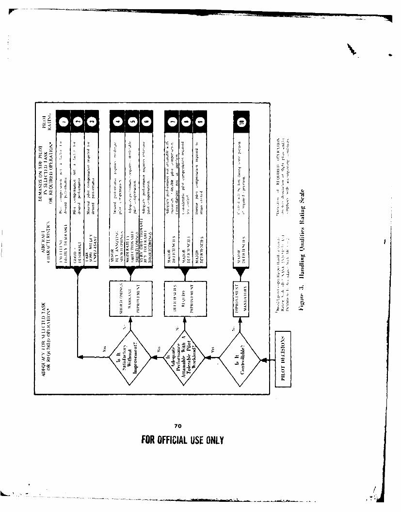
5 s
--U.- S -
- --
- - , . .
70
FOR O I U SE .
\- -\ -/ \ -
.. . CC / \
- O
FOUFIILUEOL
3- ,~ ~i z ~z S /!,., ....... .... .......................
,.',
(4) Severe icing: The rate of accumulation is such that deicing/anti-icingequipment fails to reduce or control the hazard. Immediate diversion is necessarx.
17. Results were categorized as deficiencies or shortcomings in accordance withtile following definitions (ref 16, app A):
Deficiency: A defect or malfunction discovered during the life cycle of anequipment that constitutes a safety hazard to personnel: will result in seriousdamage to the equipment if operation is continued, indicates improper designor other cause of an item or part, which seriously impairs the equipment'soperational capability. A deficiency normally disables or immobilizes tileequipment; and if occurring during test phases. will serve as a bar to typeclassification action.
Shortcoming: An imperfection or malfunction occurring during the life cycleof equipment, which should be reported and which must be corrected toincrease efficiencv and to render the equipment completely serviceable. It willnot cause an immediate breakdown, jeopardize safe operation. or materiallyreduce the usability of the material or end product. If occurring during testphases. the shortcoming should be corrected if it can be done without unduelvcomplicating tile item or inducing another undesirable characteristic such asincreased cost. weight, etc.
71
FOR OFFICIAL USE ONLY
I,

APPENDIX F. ICING FLIGHT SUMMARIES
72
- /,. --
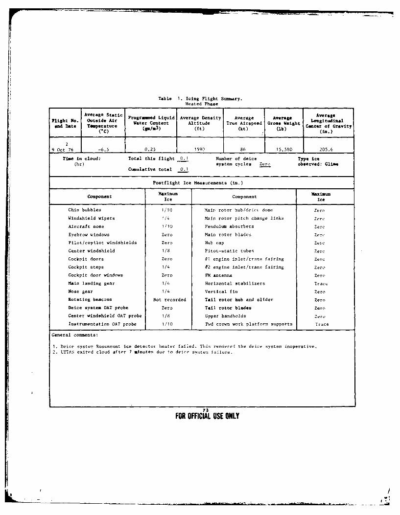
Table 1. Icing Flight Summary.Heated Phase
Average Static Averagelightrogred Liquid Average Density Average Average Lou itudialand Date Temperature Water Content Altitude True Airspeed Gros* Weight o
(C) (W=3) (ft) (kt) (lb) Center of Gravity00 (i.)
29 Oct 76 -6.5 0.25 1590 86 15,580 205.6
Time in cloud: Total this flight 0.1 Number of deice Type ice(hr) system cycles Zero observed: Glime
Cumulative total 0.1
Postflight Ice Measurements (in.)
Component Maximum Component MaximumIce Ice
Chin bubbles 1/10 Mair rotor hub/deice dome Zero
Windshield wipers 1/4 Main rotor pitch change links Zere
Aircraft nose 1/10 Pendulum absorbers Zero
Eyebrow windows Zero Main rotor blades Zero
Pilot/copilot windshields Zero Hub cap Zero
Center windshield 1/8 Pitot-static tubes Zero
Cockpit doors Zero #1 engine inlet/trans fairing Zero
Cockpit steps 1/4 #2 engine inlet/trans fairing Zero
Cockpit door windows Zero FM antenna Zero
Main landing gear 1/4 Horizontal stabilizers Trace
Nose gear 1/4 Vertical fin Zero
Rotating beacons Not recorded Tail rotor hub and slider Zero
Deice system OAT probe Zero Tail rotor blades Zero
Center windshield OAT probe 1/8 Upper handholds Zero
Instrumentation OAT probe 1/10 Fwd crown work platform supports Trace
General comments:
1. Deice system Rosemount ice detector heater failed. This renderel the deice system inoperative.2. LTTAS exited cloud after 7 minutes due to deice system failure.
73
FOR OFFICIAL USE ONLY
, /,
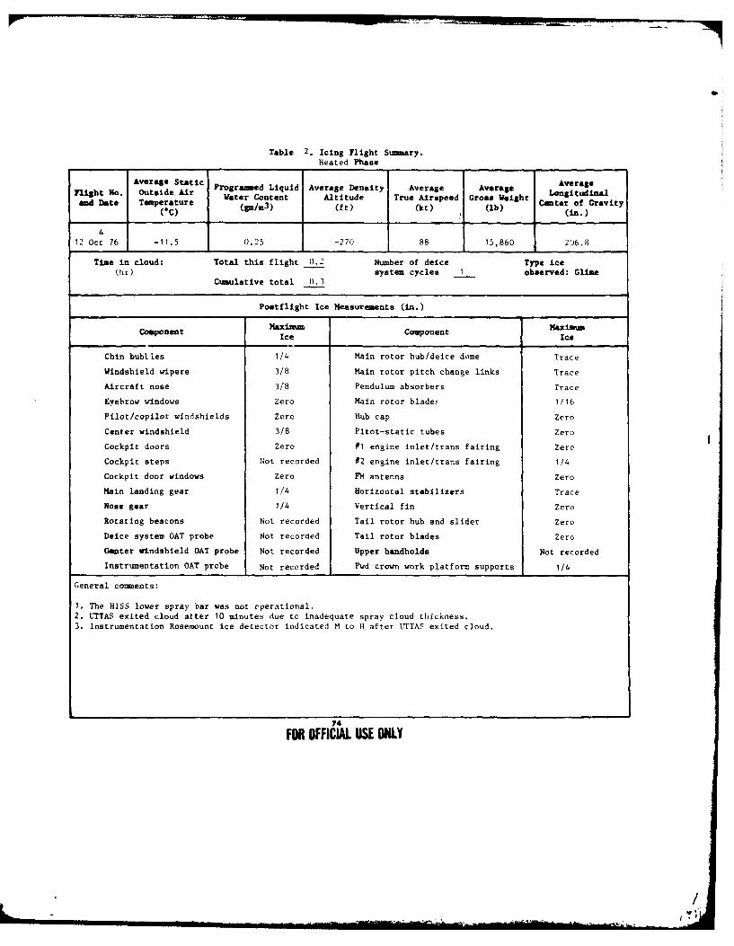
Table 2. Icing Flight Snmary.Heated Phase
Average Static Averageflight No. Outside Air Programed Liquid Average Density Average Average Aongnight No. Outsi e Water Content Altitude True Airspeed Gross Weight Longitudinaland Date Tnperature (m/m3) (ft) (kt) (Ib) Center of Gravity
(C).)
412 Oct 76 -11.5 0.25 -270 88 15,860 206.8
Tine in cloud: Total this flight 0.2 Number of deice Type ice(hr) system cycles 1 observed: Gline
Cumulative total 0.3
Postflight Ice Measurements (in.)
Maximum MaximimComponent Ice Component Ice
Chin bubtles 1/4 Main rotor hub/deice dome Trace
Windshield wipers 3/8 Main rotor pitch change links Trace
Aircraft nose 3/8 Pendulum absorbers Trace
Eyebrow windows Zero Main rotor blades 1/16
Pilot/copilot windshields Zero Hub cap Zero
Center windshield 3/8 Pitot-static tubes Zero
Cockpit doors Zero #1 engine inlet/trans fairing Zero
Cockpit steps Not recorded #2 engine inlet/trans fairing 1/4
Cockpit door windows Zero FM antenna Zero
Main landing gear 1/4 Horizontal stabilizers Trace
Nose gear 1/4 Vertical fin Zero
Rotating beacons Not recorded Tail rotor hub and slider Zero
Deice system OAT probe Not recorded Tail rotor blades Zero
Genter windshield OAT probe Not recorded Upper handholds Not recorded
Instrumentation OAT probe Not recorded Fwd crown work platform supports 1/4
General comments:
1. The HISS lower spray bar was not cperational.2. LUTTAS exited cloud after 10 minutes due to inadequate spray cloud thickness.3. Instrumentation Rosemount ice detector indicated M to H after LTTAS exited cloud.
74
FOR OFFICIAL USE ONLY
, /. ( .
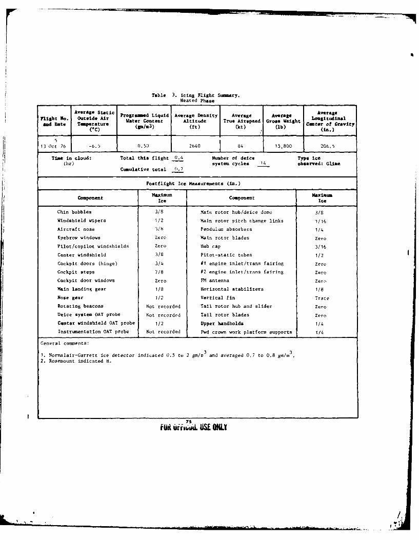
Table 3. Icing Flight Summary.Heated Phase
Average Static Programed Liquid Average Density Average Average AverageWater Content Altitude True Airspeed Gross Weight Cent Gi ty
ad bate Temperature ()(b) Ce-ter of Gravity(c) (S/m3) (ft) (kt) (lb)(in)
513 Oct 76 -6.5 0.50 2640 84 15,800 206.5
Time in cloud: Total this flight 0.4 Number of deice Type ice(hr) system cycles 14 observed: Glme
Cumulative total 0.7
Postflight Ice Measurements (in.)
Maxi~unMaximumComponent Maximum Component Ice
IceIc
Chin bubbles 3/8 Main rotor hub/deice domc 3/8
Windshield wipers 1/2 Main rotor pitch change links 1/16
Aircraft nose 3/8 Pendulum absorbers 1/4
Eyebrow windows Zero Main rotor blades Zero
Pilot/copilot windshields Zero Hub cap 3/16
Center windshield 3/8 Pitot-static tubes 1/2
Cockpit doors (hinge) 3/4 #1 engine inlet/trans fairing Zero
Cockpit steps 7/8 #2 engine inlet/trans fairing Zero
Cockpit door windows Zero FM antenna Zero
Main landing gear 1/8 Horizontal stabilizers 1/8
Nose gear 1/2 Vertical fin Trace
Rotating beacons Not recorded Tall rotor hub and slider Zero
Deice system OAT probe Not recorded Tail rotor blades Zero
Center windshield OAT probe 1/2 Upper handholds 1/4
Instrumentation OAT probe Not recorded Fwd crown work platform supports 1/4
General comments:
1. Normalair-Garrett ice detector indicated 0.5 to 2 gm/m3 and averaged 0.7 to 0.8 gm/m
3
2. Rosemount indicated H.
75lI ir wi . S ONLY
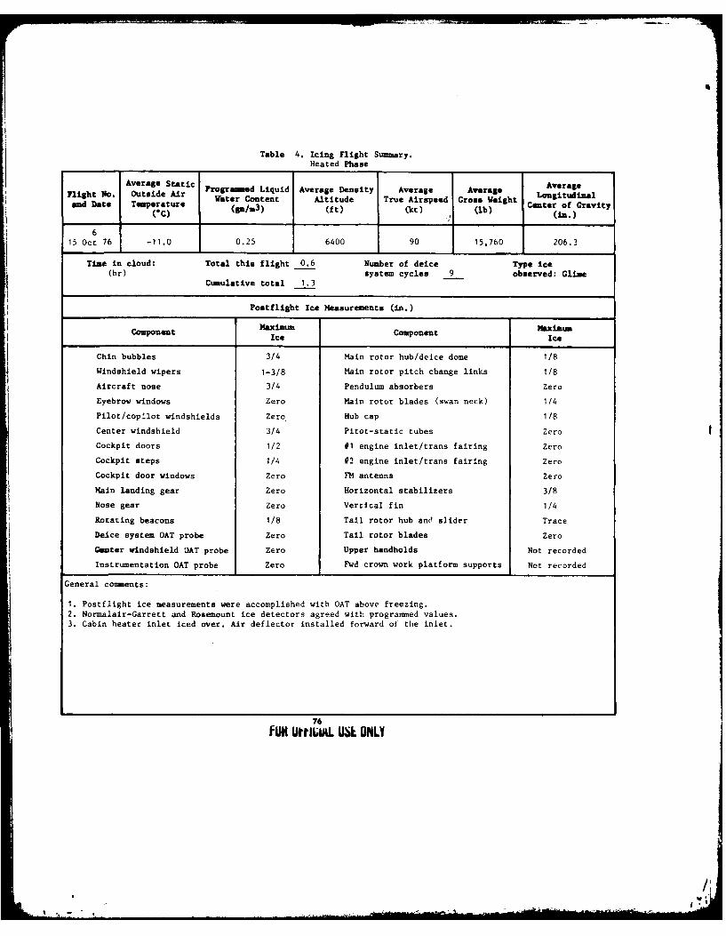
Table 4. Icing Flight Summary.Heated Phase
Average Static Programed Liquid Average Density Average Average Average
right No. Outside Air LongitudnatWater Content Altitude True Airspeed Gross Weightand Date Temperature (ft)er of Gravity(C)
6
15 Oct 76 -11.0 0.25 6400 90 15,760 206.3
Time in cloud: Total this flight 0.6 Number of deice Type ice(hr) system cycles 9 observed: Clime
Cumulative total 1.3
Postflight Ice Measurements (in.)
Component Maximum ComponentiIce Ice
Chin bubbles 3/4 Main rotor hub/deice dome 1/8
Windshield wipers 1-3/8 Main rotor pitch change links 1/8
Aircraft nose 3/4 Pendulum absorbers Zero
Eyebrow windows Zero Main rotor blades (swan neck) 1/4
Pilot/copilot windshields Zero Hub cap 1/8
Center windshield 3/4 Pitot-static tubes Zero
Cockpit doors 1/2 #1 engine inlet/trans fairing Zero
Cockpit steps 1/4 #2 engine inlet/trans fairing Zero
Cockpit door windows Zero FM antenna Zero
Main landing gear Zero Horizontal stabilizers 3/8
Nose gear Zero Vertical fin 1/4
Rotating beacons 1/8 Tail rotor hub ane slider Trace
Deice system OAT probe Zero Tail rotor blades Zero
Center windshield OAT probe Zero Upper handholds Not recorded
Instrumentation OAT probe Zero Fwd crown work platform supports Not recorded
General comments:
1. Postflight ice measurements were accomplished with OAT above freezing.2. Normalair-Garrett and Rosemount ice detectors agreed with programmed values.3. Cabin heater inlet iced over. Air deflector installed forward of the inlet.
76fUW UtILIu. USL ONLY
-,mom

Table 5. Icing Flight Summry.Heated Phase
Average Static o LAverageFlight No. Outside Ar Prograed Liquid Average Density Average AVrage LonIt naland Date Tmperature Water Content Altitude True Airspeed Gross Weight
(C) (pa/z3) (ft) (kt) (lb) Center of Gravity
1 (00(in.)
16 Oct 76 -6.0 0.75 6260 1 92 15,740 206.2
Time in cloud: Total this flight 0.2 Number of deice Type ice
(hr) Cumu5 system cycles observed: GlimeCumulative total 1.5
Postflight Ice Measurements (in.)
Component imu Component MaximumIce Ice
Chin bubbles Zero Main rotor hub/deice dome 1/4
Windshield wipers 1/2 Main rotor pitch change 'links Trace
Aircraft nose 3/4 Pendulum absorbers Zero
Eyebrow windows Zero Main rotor blades Zero
Pilot/copilot windshields Zero Hub cap 1/4
Center windshield 1/4 Pitot-static tubes Zero
Cockpit doors Runback #1 engine inlet/trans fairing Zero
Cockpit steps 7/16 92 engine inlet/trans fairing 112
Cockpit door windows Zero FM antenna Zero
Main landing gear Zero Horizontal stabilizers 1/4
Nose gear Zero Vertical fin 1/8
Rotating beacons Zero Tail rotor hub and slider Zero
Deice system OAT probe Zero Tail rotor blades Zero
Omter windshield OAT probe Not recorded Upper handholds 1/2
Instrumentation OAT probe Zero Fwd crown work platform supports 1/4
General comments:
1. Postflight ice measurements were accomplished with OAT above freezing.2. Normalair-Garrett and Posemount indications were erratic.3. Switching transient data obtained.4. Engine toppings accomplished.
77
FOR OEUIAL USE ONLY
A
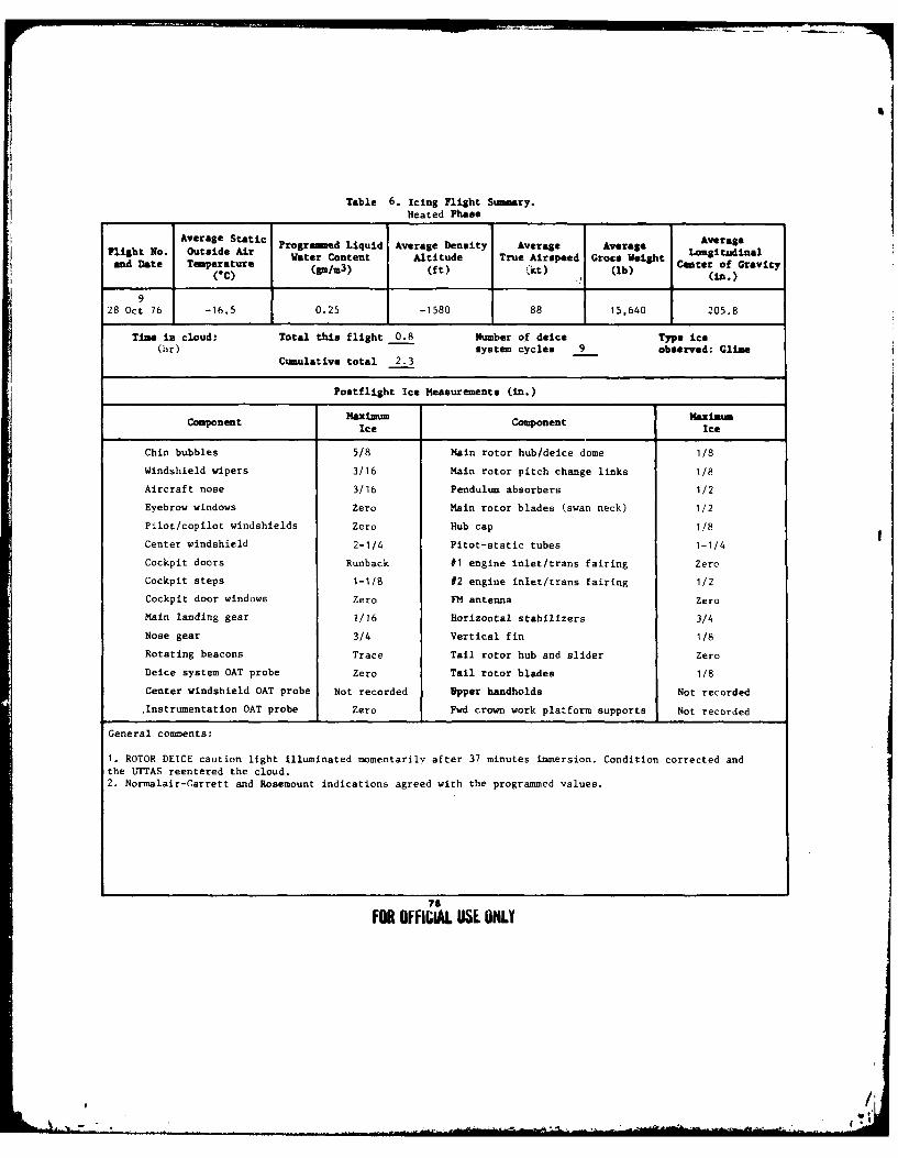
rS
Table 6. Icing Flight Summary.Heated Phase
Average Static AveragePlight No. Outside Air Programed Liquid Average Density Average Average LongitudinalandigteNo. Tou te Water Content Altitude True Airspeed Grote Weight Cter of Gravityand Date Temperature (g/ter (ft 1 0 (lb)
(C) (pl1 3 ) (ft) kt) (lb) (in.).1
928 Oct 76 -16.5 0.25 -1580 88 15,640 205.8
Time in cloud: Total this flight 0.8 Number of deice Type ice(hr) system cycles 9 observed: Clime
Cumulative total 2.3
Postflight Ice Measurements (in.)
Maximum CopnetMxim=mComponent IceComponent Ice
Chin bubbles 5/8 Main rotor hub/deice dome 1/8
Windshield wipers 3/16 Main rotor pitch change links 1/8
Aircraft nose 3/16 Pendulum absorbers 1/2
Eyebrow windows Zero Main rotor blades (swan neck) 1/2
Pilot/copilot windshields Zero Hub cap 1/8
Center windshield 2-1/4 Pitot-static tubes 1-1/4
Cockpit doors Runback #1 engine inlet/trans fairing Zero
Cockpit steps 1-1/8 #2 engine inlet/trans fairing 1/2
Cockpit door windows Zero FM antenna Zero
Main landing gear 1/16 Horizontal stabilizers 3/4
Nose gear 3/4 Vertical fin 1/8
Rotating beacons Trace Tail rotor hub and slider Zero
Deice system OAT probe Zero Tail rotor blades 1/8
Center windshield OAT probe Not recorded Upper handholds Not recorded
.Instrumentation OAT probe Zero Fwd crown work platform supports Not recorded
General comments:
1. ROTOR DEICE caution light illuminated momentarily after 37 minutes immersion. Condition corrected andthe TrTAS reentered the cloud.2. Normalair-Garrett and Rosemount indications agreed with the programmed values.
79
FOR OFFIIAL USE,, ONLY
, .5,

Table 7. Icing Flight Sary.Heated Phase
Avlght N:. Aerage Static Programed Liquid Average Density Average Average Lora lFlgh N. utid Ar Water Content Altitude True Airspeed Gros Weight Lniuia
and Date Temperature Center of Gravity(6c) (gm/m
3) (ft) (kt) (ib) (in)
1029 Oct 76 -13.0 0.50 1300 87 15,720 206.2
Time in cloud: Total this flight 0.5 Number of deice Type ice(hr) system cycles 17 observed: Glime
Cumulative total 2.8
Postflight Ice Measurements (in.)
MfaximuU Maxim--
Component Ice Component Ice
Chin bubbles 1-5/8 Main rotor hut/deice dome 1/4
Windshield wipers 11/16 Main rotor pitch change links 1/4
Aircraft nose 2 Pendulum absorbers 1
Eyebrdw windows 3 Main rotor blades (swan neck) 1/2
Pilot/copilot windshields Zero Hub cap 1/4
Center windshield 2 Pitot-static tubes 1-7/8
Cockpit doors (hinges) 1-1/2 #I engine inlet/trans fairing Zero
Cockpit steps 1-1/2 #2 engine inlet/trans fairing 1
Cockpit door windows 1/8 FM antenna Zero
Main landing gear 1/8 Horizontal stabilizers 1/2
Nose gear 1-3/4 Vertical fin 1/4
Rotating beacons Trace Tail rotor hub and slider Zero
Deice system OAT probe Trace Tail rotor blades Zero
Center windshield OAT probe 1-3/4 Upper handholds 3/4
Instrumentation OAT probe 1-3/4 Fwd crown work platform supports 1-1/2
General comments:
1. Pre- and postcloud autorotation accomplished with no significant degradition in performance.2. Erratic and inaccurate airspeed indications in level and climbing flighL.3. Normalair-Garrett and Rosemount ice detectors in('icated higher than programmed.4. Left side of lower spray bar inoperative.
79
FOR OFFICIAL USE ONLY
'i
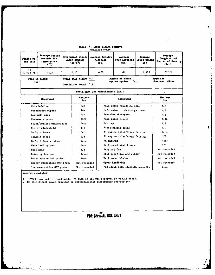
Table 8. Icing Flight Sumary.
Unheated Phase
Average Static Programed Liquid Average Density Average Average AverageFlight No. Ouside Air Water Content Altitude True Airspeed Gross Weight Longitudinal
and Date Temperature (a/3) (it) (ht) (lb) Center of Gravity(0C) ., (in.)
... . 11
30 Oct 76 -12.5 0.25 -620 89 15,980 207.3
Time in cloud: Total this flight 0.1 Number of deice Type ice(hr) system cycles Zero observed: Clime
Cumulative total 2.9
Postflight Ice Measurements (in.)
Component ime Component imuIce Ice
Chin bubbles 1/8 Main rotor hub/deice dome 1/8
Windshield wipers 1/4 Main rotor pitch change links 1/8
Aircraft nose 1/4 Pendulum absorbers I/8
Eyebrow windows Zero Main rotor blades 1/16
Pilot/copilot windshields Zero Hub cap 1/8
Center windshield 1/8 Pitot-static tubes 1/
Cockpit doors Zero #1 engine inlet/trans fairing Zero
Cockpit steps 3/8 #2 engine inlet/trans fairing 1/8
Cockpit door windows Zero F14 antenna Zero
Main landing gear Zero Horizontal stabilizers 1/8
Nose gear 1/8 Vertical fin Not recorded
Rotating beacons Trace Tail rotor hub and slider Not recorded
Deice system OAT probe Zero Tail rotor blades Not recorded
Center windshield OAT probe Not recorded Upper handholds Not recorded
Instrumentation OAT probe Not recorded 1wd crown work platform supports Zero
General comments:
1. LIUTAS remained in cloud umtil 1/4 inch of ice was observed on visual probe.
2. No significant power required or autorotational performance degradation.
so
FOR OffiuAlk SE ONLY
f I.
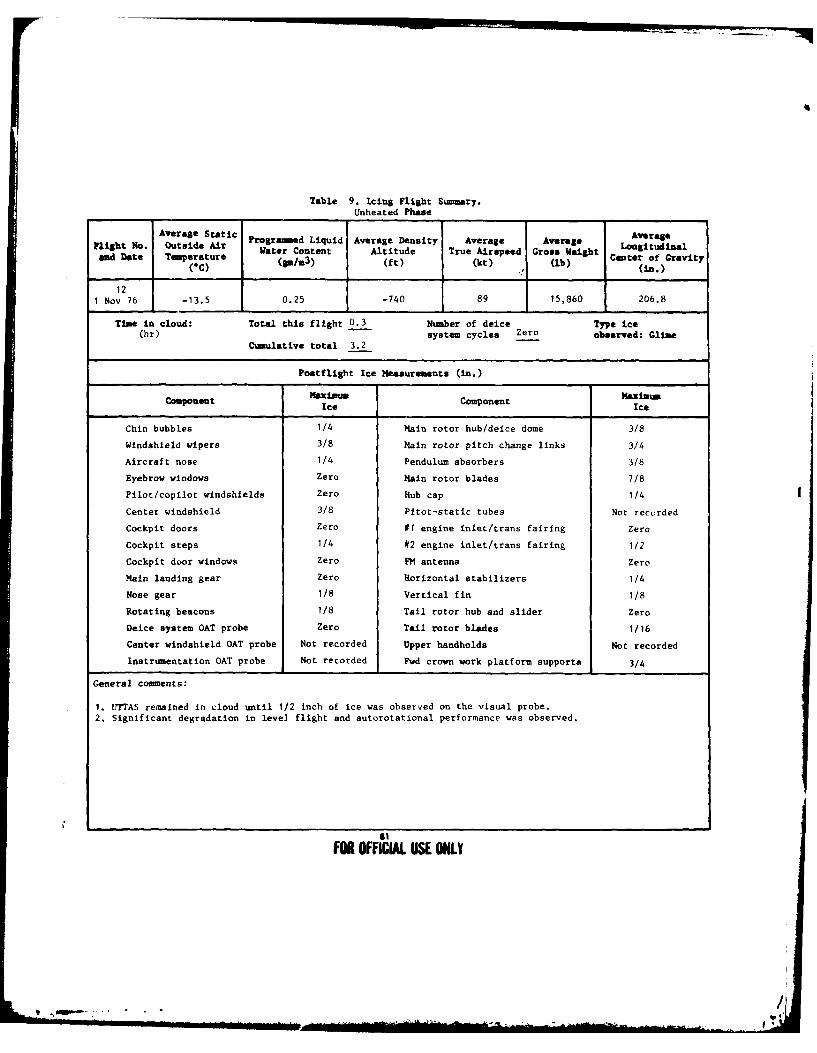
Table 9. Icing Flight Summary.Unheated Phase
Average Settc AveragefAlrht No. Outside Ai Programed Liquid Average Density Average Average Averand Date Tuperature Water Content Altitude True Airspeed Gross Weight Lnerudinai
(*C) (p/3) (ft) (kt) (lb) (In.)
121 Nov 76 -13.5 0.25 -740 89 15,860 206.8
Time in cloud: Total this flight 0.3 Number of deice Type ice(hr) system cycles Zero observed: Glise
Cumulative total 3.2
Postflight Ice Measurements (in.)
CoMponent Component maximumCopnetIce Ice
Chin bubbles 1/4 Main rotor hub/deice dome 3/8
Windshield wipers 3/8 Main rotor pitch change links 3/4
Aircraft nose 1/4 Pendulum absorbers 3/8
Eyebrow windows Zero Main rotor blades 7/8
Pilot/copilot windshields Zero Hub cap 1/4
Center windshield 3/8 Pitot-static tubes Not recorded
Cockpit doors Zero #1 engine inlet/trans fairing Zero
Cockpit steps 1/4 #2 engine inlet/trans fairing 1/2
Cockpit door windows Zero PH antenna Zero
Main landing gear Zero Horizontal stabilizers 1/4
Nose gear 1/8 Vertical fin 1/8
Rotating beacons 1/8 Tail rotor hub and slider Zero
Deice system OAT probe Zero Tail rotor blades 1/16
Center windshield OAT probe Not recorded Upper handholds Not recorded
Instrumentation OAT probe Not recorded Pwd crown work platform supports 3/4
General comments:
1. UTTAS remained in cloud until 1/2 inch of ice was observed on the visual probe.2. Significant degradation in level flight and autorotational performance was observed.
F 1FOR OFFICIAL USE ONLY
I.

APPENDIX G. TEST DATA
82
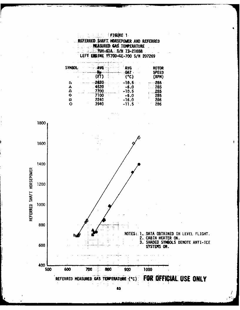
REPEREDi MMMt ORSPOM AND REEREAWURV GA0EW'ERATURE
i~m~& ~ii471-2165&LE iEF RE. Yl .4- 700 S/N 207269
SYpBOL - ,- AVG ROTOR-- -- i -6--- -MT-' SPEED
r, .... . --2Wa20---.. . .-10.5- "--285
4~2O-6.0 285
o' -6.0o 2240 -16.0 286o 3940 -11.5 286
1800
1600
1400
L:J
" 1200
"1000
L6LJ
800 ..::,:.NOTES:. ..... DATA OBTAINED IN LEVEL FLIGHT.
600 2. CABIN HEATER ON.3. SADE SYMBOLS DENOTE ANTI-ICE
600 .. SYS S ON.
400
S00 600 700~ S0 .00 10,00
REFERRED M°UREFDR GAS T TOE(C) 'FOR' OFFICIAL; USE ONLY63 /
C , '9 I

REF ERR EDS RHAPT" 408W E61AND AE&tED-MEA,5UREDAA GAS K~PATURE.. I.,
YUH-61A :!,'S/N;7A'- 216'58 1IAR IGHT Etll"INE VTO .... ......~7
SYMBOL AVGAV tOHp. OAT
FTY; (RPM-)2620.:;1 :S
A4520 -60 857700 ~,10.5 87100 o-6.0 -285-
O2240 -16.0 286:o3940 :.- -11.5- 286 -
1800
11400
000
8. 100
c4 00
00 60 70 80 90 10
REFR0E SYSTEMSS EPEATR r O ON.CA UEOL
4004

APPENDIX H. PHOTOGRAPHS
as
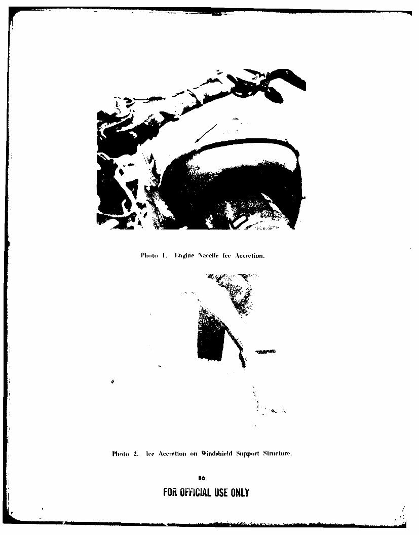
Photo 1. Engine Nacelle Ice Accretion.
Photo 2. l-e Accretion on Windshield Suipport Structure.
86
FOR OFFIIAL USE ONLY
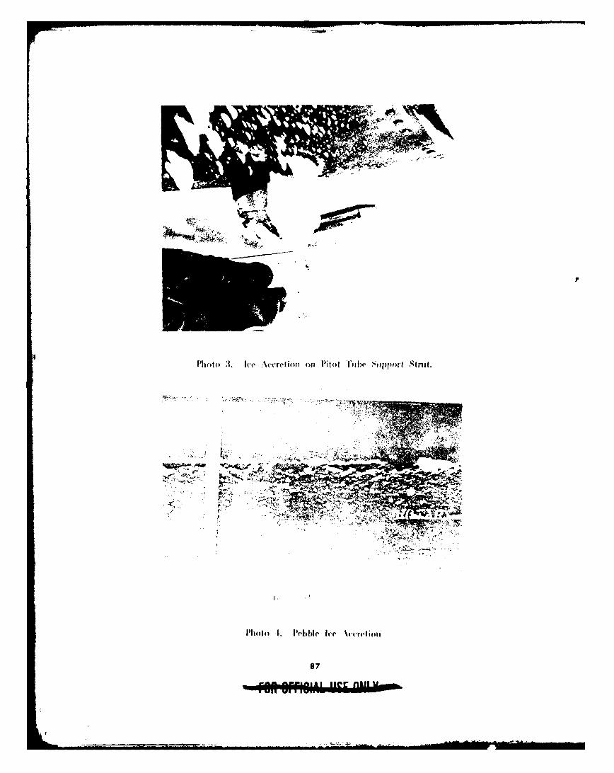
Phto~( 3, Ice Accrefit ml Pil~tf lhil SoppEorI Stnd.
I'Ioto t1. P~ebbleI Ice \('(retliotl
87
-W iil