Embed Size (px)
Citation preview
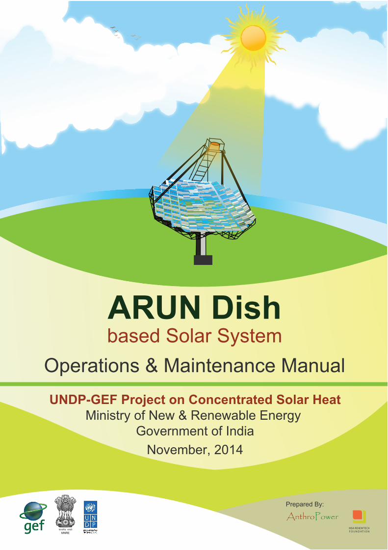
ARUN Dishbased Solar System
Operations & Maintenance Manual
lR;eso t;rsMNRE
November, 2014
UNDP-GEF Project on Concentrated Solar HeatMinistry of New & Renewable Energy
Government of India
MSA RENEWTECHF O U N D AT I O N
Prepared By:
1
Contents
Acknowledgement 3
About This Manual 5
1.0 General Description 6
2.0 Specifications 72.1 System Specification 72.2 Sub-System Specifications 72.3 Module Specification 10
3.0 Safety Information 113.1 General Safety Risks and Precautions 123.2 Use of Personal Protective Equipment (PPE) 123.3 General precautions during operation and maintenance 123.4 Chemicals used and health related precautions 133.5 IBR (Indian Boiler Regulations) Safety Regulations 143.6 How a Paraboloid Dish Works 153.7 How Tracking Works 153.8 How the Control System of the Dish Works 173.9 How the Circulation System Works 17
4.0 Operating the System 174.1 Start-up Sequence 174.2 Start-up Precautions 184.3 Normal Operation, Monitoring and Error Control 184.4 Exceptions and Backup 204.5 Shutdown Sequence 204.6 Shutdown Sequence in Manual Mode 20
5.0 Maintenance 215.1 Predictive Maintenance 215.2 Preventive Maintenance 215.3 Consumable Replacement 225.4 Routine Maintenance 225.5 Troubleshooting 225.6 Do’sandDon’ts 23
Appendix 1: Arun Solar Controller 24
Appendix 2: Valves and Fittings 25
Appendix 3: Pressure Selection for Expansion Tank 26
Appendix 4: Maintenance Activities 27
Appendix 5: Maintenance Record Form 29
Standard Task Procedure: Cleaning of ARUN Dish 30

2
3
Acknowledgement
This manual is the result of extensive input from Clique Solar Pvt. Ltd. We express our sincere gratitude to the following individuals from the company:
• Shri Ashok Paranjape
• Dr. Shireesh B. Kedare
• Shri Abhishek Bhatewara
• Shri Anil Pednekar

4
5
About This Manual
This document describes a ARUN Dish system and the procedures needed to operate and maintain it successfully. The document is intended primarily for instructors, supervisors and engineers to train the site level technicians.
The document maintains a focus on the practical day-to-day tasks of operating ARUN Dish. The design of the system and the engineering considerations behind its operation are not covered unless they have a direct bearing on operational decisions.
6
1.0 General Description
Heatfromsun’srayscanbeharnessedtoprovideheattoavarietyofapplicationssuchascooking,cooling,industrialprocessheating,desalinationandgeneratingelectricity.Butingeneral,Sun’sraysaretoo diffuse to be of direct use in these applications. So solar concentrators are used to collect and concentratesun’sraystoheatupaworkingfluidtotherequiredtemperaturethemakeSun’sheatsuitable for these applications
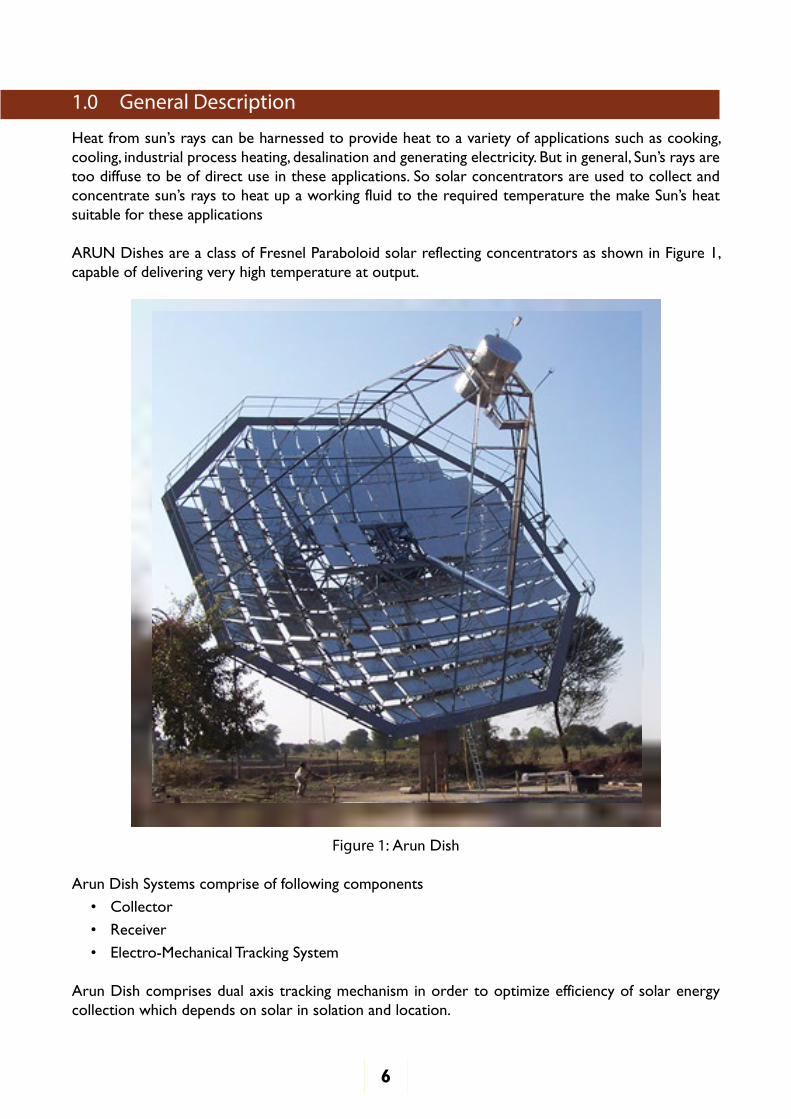
ARUN Dishes are a class of Fresnel Paraboloid solar reflecting concentrators as shown in Figure 1, capable of delivering very high temperature at output.
Figure 1: Arun Dish
Arun Dish Systems comprise of following components
• Collector
• Receiver
• Electro-Mechanical Tracking System
Arun Dish comprises dual axis tracking mechanism in order to optimize efficiency of solar energy collection which depends on solar in solation and location.
7
2.0 Specifications
2.1 System SpecificationA system to generate heat from ARUN Dish consists of a number of sub-systems and components. However, it is easy to see what the entire system does by specifying just a few basic parameters. These parameters are explained in Table 1 below.
Table 1: System Specification
Sr. No Specification Example Values Description
1 Nominal Rating Arun 160: 6 Lkcal/dayArun 100: 4 Lkcal/dayArun 30: 1 Lkcal/day
The heat output provided on a clear sunny day
2 Basic Module Fresnel Paraboloid reflecting concentrator tracking the Sun on two axes
The basic unit for collecting, concentratingandcapturingsun’sheat
3 Working Fluid Water/ oil The fluid through which heat from the sun is transferred to the end application
4 System Temperature Range
180°C(Asperrequiredapplication, can go upto 350°C)
The temperature range at which the working fluid operates
5 End Use Application Industrial process steam The final use to which the system is put
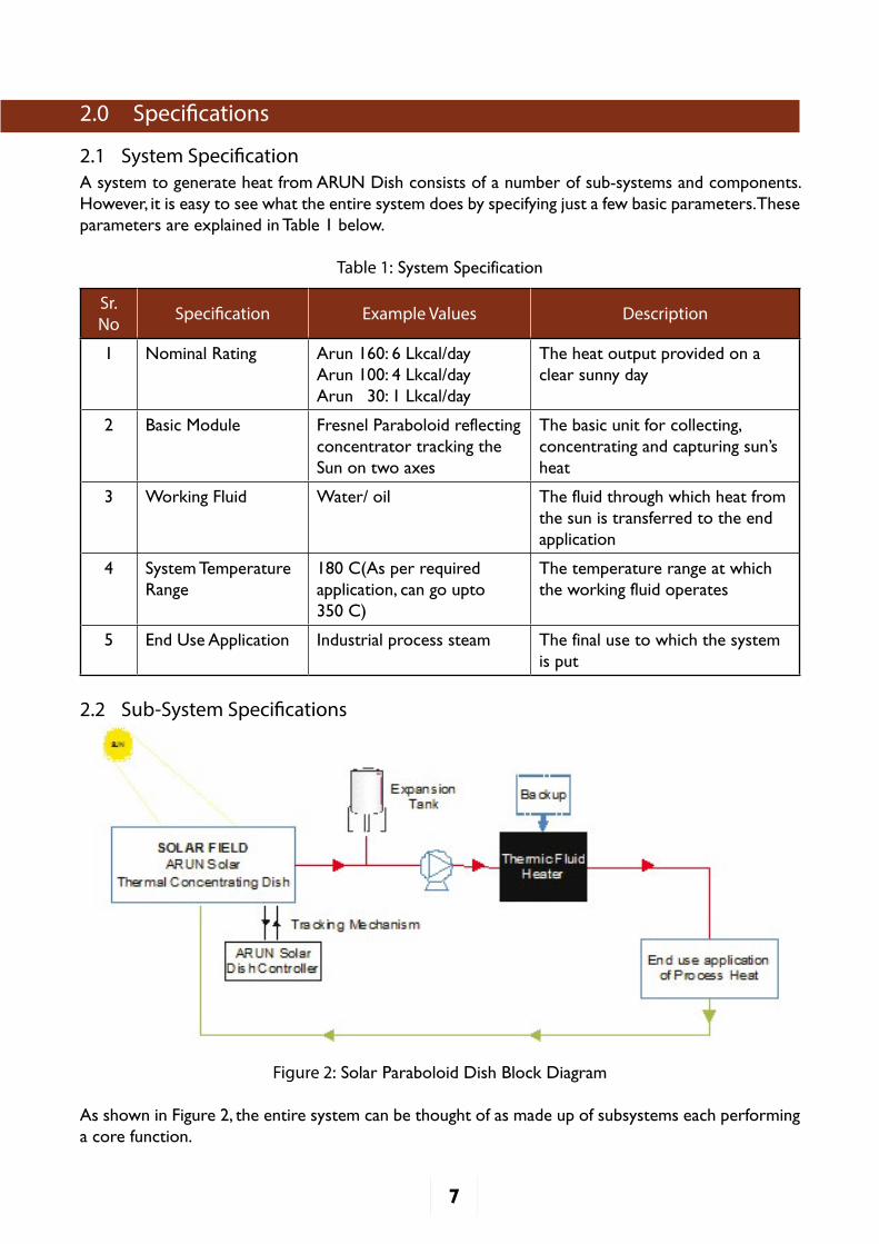
2.2 Sub-System Specifications
Figure 2: Solar Paraboloid Dish Block Diagram
As shown in Figure 2, the entire system can be thought of as made up of subsystems each performing a core function.
8
The receiving subsystem collects solar radiation in the solar field from paraboloid reflecting collectors and transfers it to working fluid such as water or oil.
The tracking subsystem acts as a support to the receiving subsystem. It maximizes the solar energy captured by movingsolar collectors towards the sun throughout the day and throughout the seasons.
The circulation subsystem carries fluid and transfers the heat received by it to the end use application. Fluid circulates in the system at a certain desired rate to quickly and efficiently transfer the received heat from solar field to end use application. Circulation subsystem has a number of components such as pipes, pumps and valves to control fluid flow and temperature.
Finally, the control Mechanism is the brain behind tracking and circulation system. It sends signals to these systems to control the tracking of the receiver based on pressure and temperature of the circulating fluid.
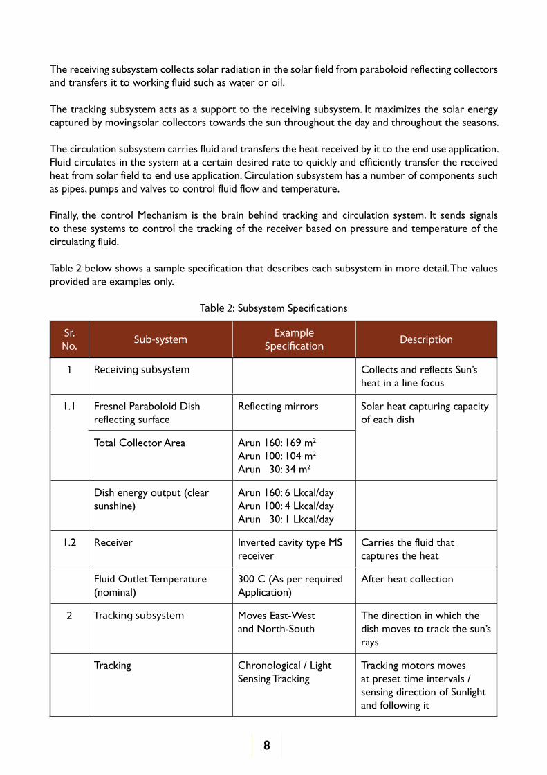
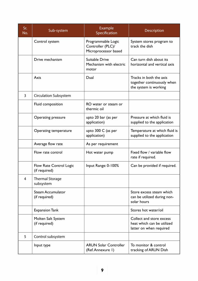
Table 2 below shows a sample specification that describes each subsystem in more detail. The values provided are examples only.
Table 2: Subsystem Specifications
Sr. No. Sub-system Example
Specification Description
1 Receiving subsystem CollectsandreflectsSun’sheat in a line focus
1.1 Fresnel Paraboloid Dish reflecting surface
Reflecting mirrors Solar heat capturing capacity of each dish
Total Collector Area Arun 160: 169 m2
Arun 100: 104 m2
Arun 30: 34 m2
Dish energy output (clear sunshine)
Arun 160: 6 Lkcal/dayArun 100: 4 Lkcal/dayArun 30: 1 Lkcal/day
1.2 Receiver Inverted cavity type MS receiver
Carries the fluid that captures the heat
Fluid Outlet Temperature (nominal)
300°C(AsperrequiredApplication)
After heat collection
2 Tracking subsystem Moves East-Westand North-South
The direction in which the dishmovestotrackthesun’srays
Tracking Chronological / Light Sensing Tracking
Tracking motors moves at preset time intervals / sensing direction of Sunlight and following it
9
Sr. No. Sub-system Example
Specification Description
Control system Programmable Logic Controller (PLC)/ Microprocessor based
System stores program to track the dish
Drive mechanism Suitable Drive Mechanism with electric motor
Can turn dish about its horizontal and vertical axis
Axis Dual Tracks in both the axis together continuously when the system is working
3 Circulation Subsystem
Fluid composition RO water or steam or thermic oil
Operating pressure upto 20 bar (as per application)
Pressure at which fluid is supplied to the application
Operating temperature upto300°C(asperapplication)
Temperature at which fluid is supplied to the application
Average flow rate As per requirement
Flow rate control Hot water pump Fixed flow / variable flow rate if required.
Flow Rate Control Logic(if required)
Input Range: 0-100% Can be provided if required.
4 Thermal Storage subsystem
Steam Accumulator(if required)
Store excess steam which can be utilized during non-solar hours
Expansion Tank Stores hot water/oil
Molten Salt System(if required)
Collect and store excess heat which can be utilized latter on when required
5 Control subsystem
Input type ARUN Solar Controller (Ref. Annexure 1)
To monitor & control tracking of ARUN Dish
10
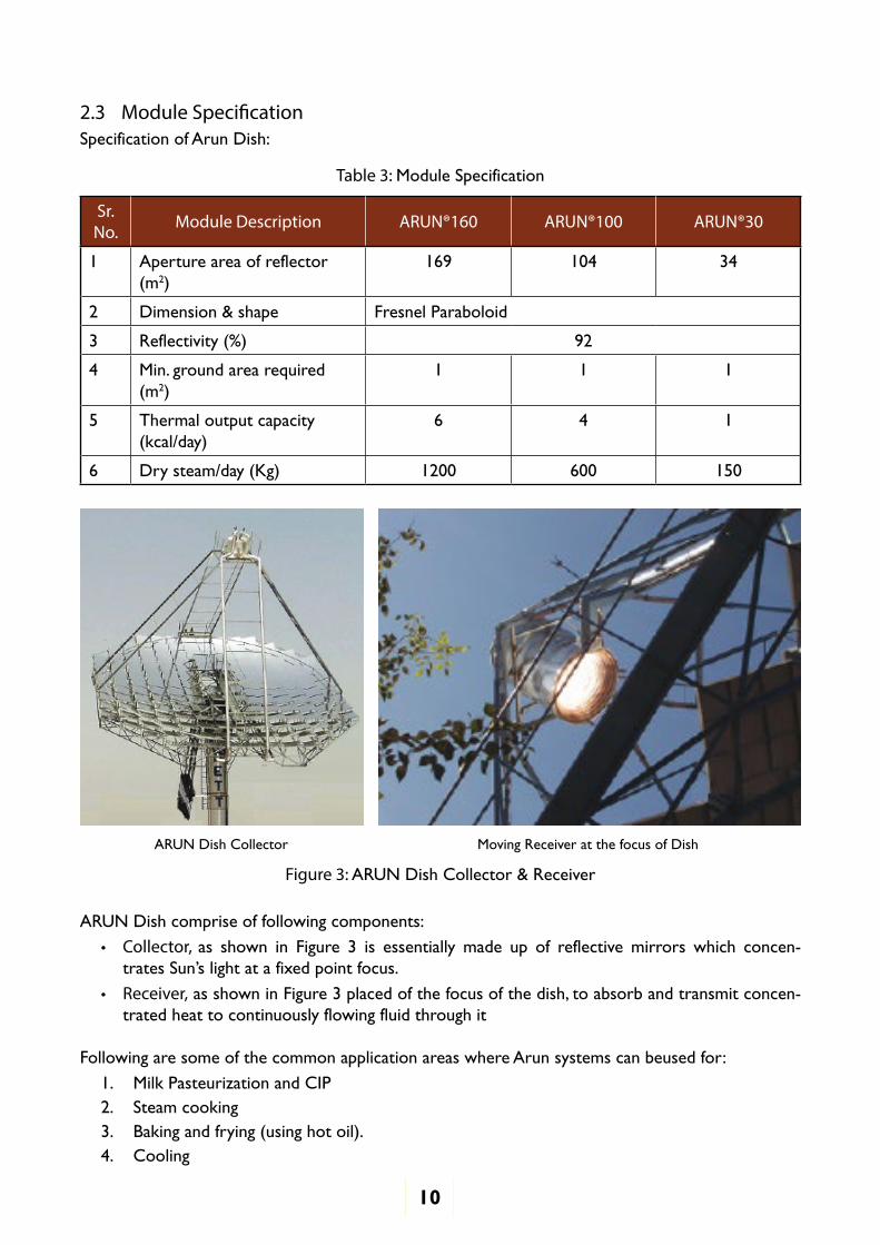
2.3 Module SpecificationSpecification of Arun Dish:
Table 3: Module Specification
Sr. No. Module Description ARUN®160 ARUN®100 ARUN®30
1 Aperture area of reflector (m2)
169 104 34
2 Dimension & shape Fresnel Paraboloid
3 Reflectivity (%) 92
4 Min. ground area required (m2)
1 1 1
5 Thermal output capacity (kcal/day)
6 4 1
6 Dry steam/day (Kg) 1200 600 150
ARUN Dish Collector Moving Receiver at the focus of Dish
Figure 3: ARUN Dish Collector & Receiver
ARUN Dish comprise of following components:
• Collector, as shown in Figure 3 is essentially made up of reflective mirrors which concen-tratesSun’slightatafixedpointfocus.
• Receiver, as shown in Figure 3 placed of the focus of the dish, to absorb and transmit concen-trated heat to continuously flowing fluid through it
Following are some of the common application areas where Arun systems can beused for:
1. Milk Pasteurization and CIP2. Steam cooking3. Baking and frying (using hot oil).4. Cooling
11
5. Desalination / Effluent Drying6. Process Heating7. Power Generation8. Laundry9. Hot air for powder coating / paint curing
The role of each module is explained in more detail below:
ARUN Dish
• Fresnel Paraboloid reflecting concentrator, which concentrates sunlight at a focus point which moves with the Sun
• Works on dual-axis tracking mechanism, concentrate sunlight at a point focus
Receiver
• Inverted cavity type MS receiver
• Collects concentrated sunlight and transmits the energy to fluid through it
Expansion Tank
• Maintains the pressure of circulating fluid in a closed system, allowing water to expand with rising temperature
• Pressure is maintained by adding nitrogen, which also eliminates corrosion by inhibiting expo-sure of water vapor to oxygen
• Minimizes pressure surge(to reduce water hammering effect)to save pipeline from damage
Hot Water Pump
• Pumps water to the solar field, and maintain water flow rate in the circulation system
• Flow rate of water circulating in closed system is maintained / controlled through the SCADA system (if required) / controller.
Thermal Storage Tank
• Uses buffering technique, i.e. it store excess heat generated by the Solar field, which can be utilizedduring non-solar hrs
• Stores a phase change material which can transform from solid to liquid state to store heat, and vice-versa to loose heat gained by it
Water treatment System (if required)
• The feed water needs to be treated to avoid scaling inside the circulation systems. Dosing Sys-tems add controlled volume of concentrated chemicals to feed water.
3.0 Safety Information
An understanding of safety involves three aspects:
• A general awareness of safety risks on the site
• Knowledge of protective equipment that should be available on-site and the specific scenarios when they should be used
• Safety precautions that should be followed for every activity that is undertaken on-site
12
This section provides general coverage of all of the above aspects. In addition, the safety risks and precautions related to every task can be found in the Standard Task Procedures in the annexure.
NOTE: This is a generalized discussion of safety aspects on ARUN Dishes. By no means is this a comprehensive treatment of all safety risks and precautions. For a more complete understanding of safety, please refer to the manufacturer manual or OSHA guidelines.
3.1 General Safety Risks and Precautions• Thefluidisatatemperatureabove110°C,whichisscaldingtemperature.Soanycontactwith
fluid should be avoided• Pipes and other metal parts carrying the fluid would be at the same temperature and hence are
insulated. However, at any exposed portion near insulated hose pipes, the temperature can be high enough to cause skin burns
• Fluid pressure maybe pressurized which is higher than atmospheric pressure. Thus, on any open-ing / breakage / crack etc., the fluid can come out as a jet and come into contact with the body
• Take care that there is no inflammable material near the focus• Avoid looking at reflective surfaces with naked eyes for long duration• If liquid circulating in the system has health hazards, use protective uniform and mask to avoid
inhalation or exposure to it
3.2 Use of Personal Protective Equipment (PPE)
Note: Please refer to the manufacturer’s manual for the specific make and grade of each piece of equipment to be used.
• Hand gloves of appropriate thickness and insulation to protect against hot surfaces• Rubber hand gloves to protect against electrical shock• Industrial safety shoes while walking on site• Safety Goggles• Welding Goggles to look at receiver• Protective Helmet• Safety harness while working on dishto prevent falls
3.3 General precautions during operation and maintenance
Pipe line and equipment
• Ensure isolating valves are closed to stop the flow of fluid before attending to a module / com-ponent
• Drain hot fluid first through drain valve and depressurize through vent valves before opening any equipment to avoid any chance of contact
• Wear hand gloves while removing insulation to avoid skin contact with hot surfaces• Loosen screws and connections only when the system is not under pressure• When ever fluid is to be drained by opening flanges or coupling, before opening drainage valves
stand slightly away from the pipeto avoid fluid spills from hitting you
Collector and Receiver
• Reflection from collector surface could be intense and can cause harm to your eyes. Protective filtered goggles should be worn while working on reflective surfaces in the sun
13
Expansion Tank
• Close top/bottom needle valves oflevel gauge before removing level gauge to prevent contact with hot fluid
• It generally stores liquid at high pressure, and hence a safe distance must be maintained from vent (outlet), used to control expansion tank pressure
• If the insulation of tanks is to be removed, then always use gloves to remove glass wool, as it is an irritant to the skin and can cause severe itching on your hand
Thermal storage tank has a phase change material, which melts and turns fluid at a certain temperature. Take care to avoid any contact with it.
3.4 Chemicals used and health related precautions
Soft Water
• May have been treated for specific purpose
• Safety relief valve should be in upright position at a height away from the reach of system operator
Thermic Fluid
• Thermic Fluid may be pressurized and is working at high temperature range hence precaution needs to be taken while operating and maintaining the system, as any human contact with the hot system thermic fluid can cause fatal injuries
• Maintain good ventilation around equipment area to provide quick cooling of any leaks, also it will disperse any unreacted vapors
• Safety Relief Valve should be connected to a vessel to discharge thermic fluid safely, as fluid may be toxic and unsafe for release to environment
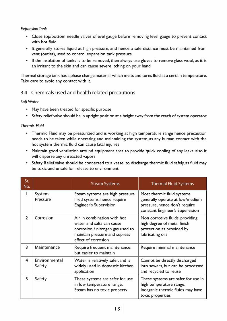
Sr. No. Steam Systems Thermal Fluid Systems
1 System Pressure
Steam systems are high pressure fired systems, hence require Engineer’sSupervision
Most thermic fluid systems generally operate at low/medium pressure,hencedon’trequireconstantEngineer’sSupervision
2 Corrosion Air in combination with hot water and salts can cause corrosion / nitrogen gas used to maintain pressure and supress effect of corrosion
Non corrosive fluids, providing high degree of metal finish protection as provided by lubricating oils
3 Maintenance Require frequent maintenance, but easier to maintain
Require minimal maintenance
4 Environmental Safety
Water is relatively safer, and is widely used in domestic kitchen application
Cannot be directly discharged into sewers, but can be processed and recycled to reuse
5 Safety These systems are safer for use in low temperature range.Steam has no toxic property
These systems are safer for use in high temperature range.Inorganic thermic fluids may have toxic properties
14
3.5 IBR (Indian Boiler Regulations) Safety Regulations
Steam boilers exceeding 22.75 Liters capacity and steam pipelines where steam pressure exceeds 3.5 Kg/cm2 come under the scanner of IBR regulations.
All valves and fittings should be as per IBR specifications with test certification for each valve. During repair work technician should follow IBR Regulations and specifications for tasks such as procuring material, welding and plumbing works near Steam Boilers and Steam Pipelines. Operator should refer tomanufacturer’sspecificationsforvalve/fittingtobereplaced.
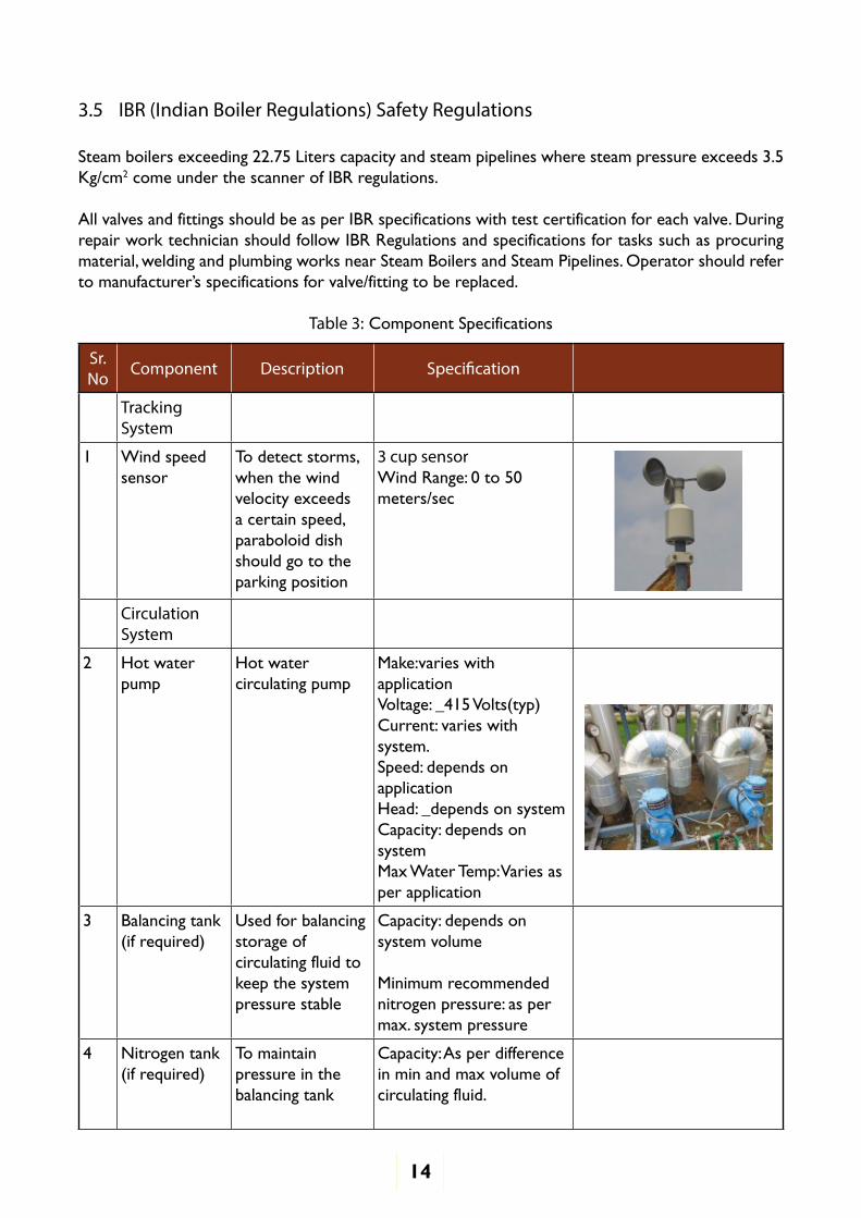
Table 3: Component Specifications
Sr. No Component Description Specification
Tracking System
1 Wind speed sensor
To detect storms, when the wind velocity exceeds a certain speed, paraboloid dish should go to the parking position
3 cup sensorWind Range: 0 to 50 meters/sec
Circulation System
2 Hot water pump
Hot water circulating pump
Make:varies with applicationVoltage: _415 Volts(typ)Current: varies with system. Speed: depends on applicationHead: _depends on system Capacity: depends on systemMax Water Temp: Varies as per application
3 Balancing tank(if required)
Used for balancing storage of circulating fluid to keep the system pressure stable
Capacity: depends on system volume
Minimum recommended nitrogen pressure: as per max. system pressure
4 Nitrogen tank(if required)
To maintain pressure in the balancing tank
Capacity: As per difference in min and max volume of circulating fluid.
15
Sr. No Component Description Specification
5 Valves Used for flow control
Valve pressure rating: suitable for system pressure_ barMaximum temperature: suitable for system temperature C
Material: CS or Stainless steel
Manual or Automatic (controlled by PLC)
End connection used:Flange or thread end
Open bonnet (for water and steam) or closed bonnet (for thermic oil)
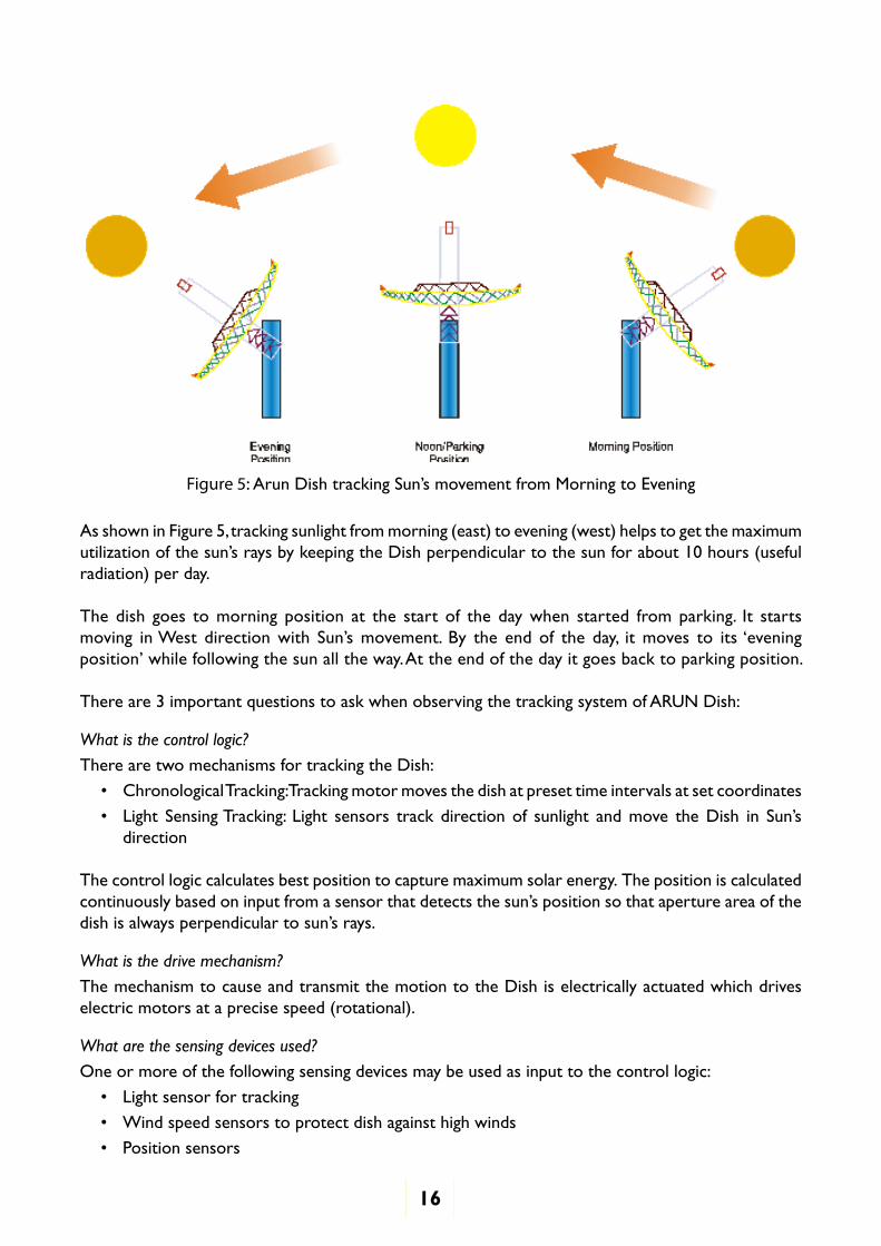
3.6 How a Paraboloid Dish WorksFresnel Paraboloid Collector concentrates solar radiation over a small region (focus). The dish is positionedsuchthat itsapertureplane isperpendicular to thesun’srays.Figure3 illustrateshowARUN Dish tracks sun in a single axis to transfer energy to fluid circulating through receiver.
Figure 4: Arun Dish consisting of a Fresnel Paraboloid collector to reflect light and receiver where heat is absorbed
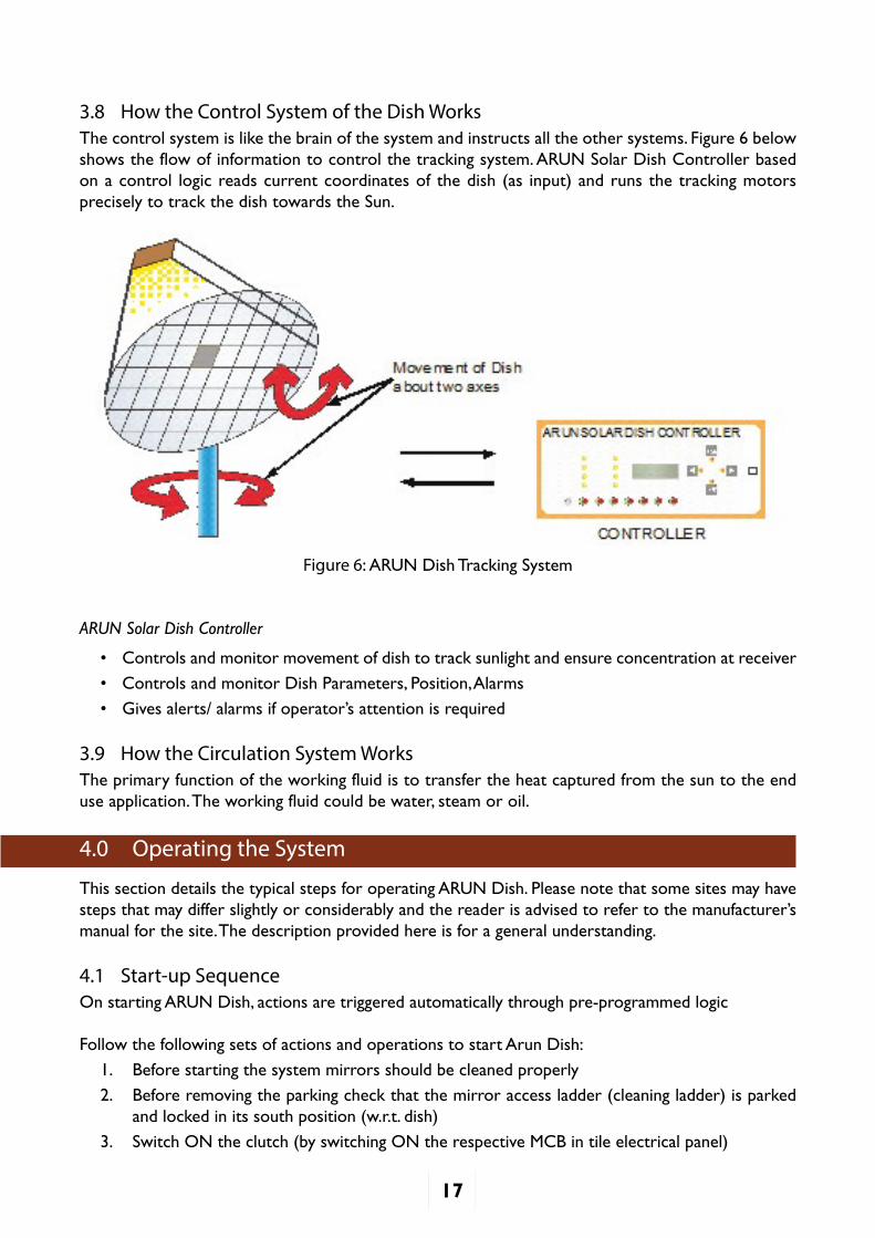
3.7 How Tracking WorksInARUNDish,collectorconcentratesunlightonreceiver tube formingapointfocus.Withsun’smovement from east to west (diurnal) and north to south (seasonal), the collector continuously tracksabouttwoaxis,trackingsun’sradiationandmaintainingthefocusofcollectoronreceiver.Figure 5 below illustrates this concept.
16
Figure 5:ArunDishtrackingSun’smovementfromMorningtoEvening
As shown in Figure 5, tracking sunlight from morning (east) to evening (west) helps to get the maximum utilizationofthesun’sraysbykeepingtheDishperpendiculartothesunforabout10hours(usefulradiation) per day.
The dish goes to morning position at the start of the day when started from parking. It starts moving inWest directionwith Sun’smovement. By the endof the day, itmoves to its‘eveningposition’whilefollowingthesunalltheway.Attheendofthedayitgoesbacktoparkingposition.
There are 3 important questions to ask when observing the tracking system of ARUN Dish:
What is the control logic?
There are two mechanisms for tracking the Dish:
• Chronological Tracking: Tracking motor moves the dish at preset time intervals at set coordinates
• Light SensingTracking: Light sensors track directionof sunlight andmove theDish in Sun’sdirection
The control logic calculates best position to capture maximum solar energy. The position is calculated continuouslybasedoninputfromasensorthatdetectsthesun’spositionsothatapertureareaofthedishisalwaysperpendiculartosun’srays.
What is the drive mechanism?
The mechanism to cause and transmit the motion to the Dish is electrically actuated which drives electric motors at a precise speed (rotational).
What are the sensing devices used?
One or more of the following sensing devices may be used as input to the control logic:
• Light sensor for tracking
• Wind speed sensors to protect dish against high winds
• Position sensors
17
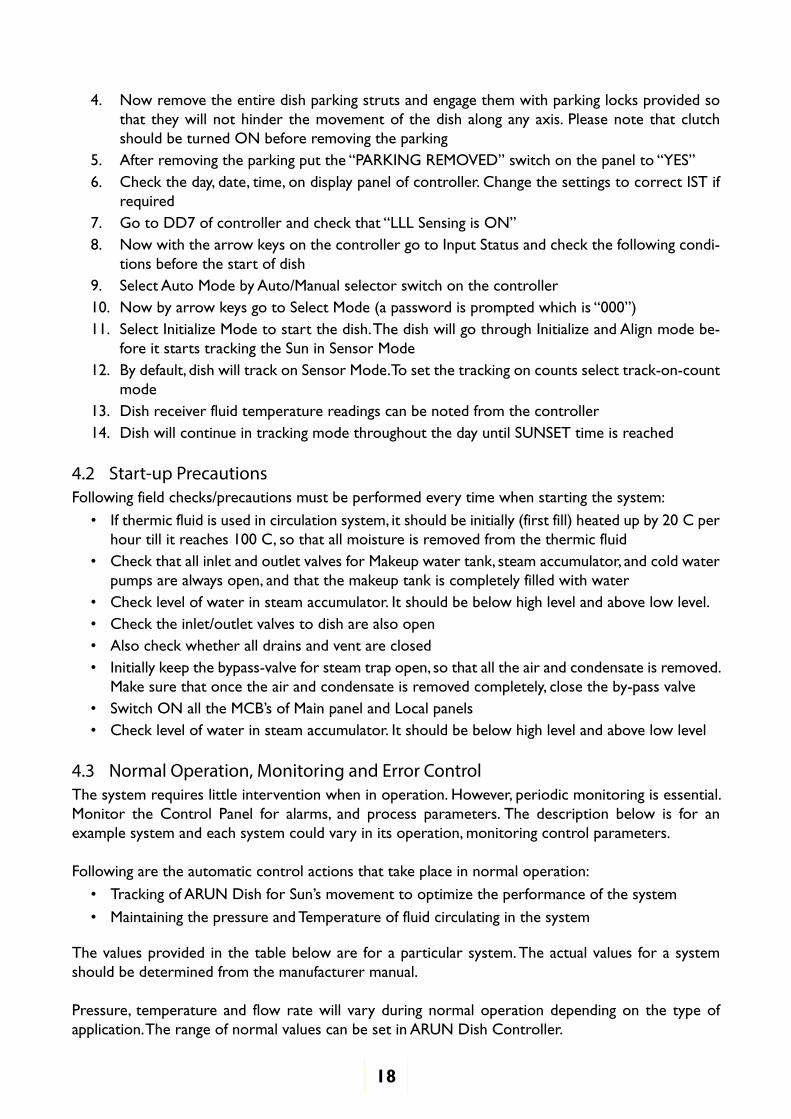
3.8 How the Control System of the Dish WorksThe control system is like the brain of the system and instructs all the other systems. Figure 6 below shows the flow of information to control the tracking system. ARUN Solar Dish Controller based on a control logic reads current coordinates of the dish (as input) and runs the tracking motors precisely to track the dish towards the Sun.
Figure 6: ARUN Dish Tracking System
ARUN Solar Dish Controller
• Controls and monitor movement of dish to track sunlight and ensure concentration at receiver
• Controls and monitor Dish Parameters, Position, Alarms
• Givesalerts/alarmsifoperator’sattentionisrequired
3.9 How the Circulation System WorksThe primary function of the working fluid is to transfer the heat captured from the sun to the end use application. The working fluid could be water, steam or oil.
4.0 Operating the System
This section details the typical steps for operating ARUN Dish. Please note that some sites may have stepsthatmaydifferslightlyorconsiderablyandthereaderisadvisedtorefertothemanufacturer’smanual for the site. The description provided here is for a general understanding.
4.1 Start-up SequenceOn starting ARUN Dish, actions are triggered automatically through pre-programmed logic
Follow the following sets of actions and operations to start Arun Dish:
1. Before starting the system mirrors should be cleaned properly
2. Before removing the parking check that the mirror access ladder (cleaning ladder) is parked and locked in its south position (w.r.t. dish)
3. Switch ON the clutch (by switching ON the respective MCB in tile electrical panel)
18
4. Now remove the entire dish parking struts and engage them with parking locks provided so that they will not hinder the movement of the dish along any axis. Please note that clutch should be turned ON before removing the parking
5. Afterremovingtheparkingputthe“PARKINGREMOVED”switchonthepanelto“YES”6. Check the day, date, time, on display panel of controller. Change the settings to correct IST if
required7. GotoDD7ofcontrollerandcheckthat“LLLSensingisON”8. Now with the arrow keys on the controller go to Input Status and check the following condi-
tions before the start of dish9. Select Auto Mode by Auto/Manual selector switch on the controller10. NowbyarrowkeysgotoSelectMode(apasswordispromptedwhichis“000”)11. Select Initialize Mode to start the dish. The dish will go through Initialize and Align mode be-
fore it starts tracking the Sun in Sensor Mode12. By default, dish will track on Sensor Mode. To set the tracking on counts select track-on-count
mode13. Dish receiver fluid temperature readings can be noted from the controller14. Dish will continue in tracking mode throughout the day until SUNSET time is reached
4.2 Start-up PrecautionsFollowing field checks/precautions must be performed every time when starting the system:
• Ifthermicfluidisusedincirculationsystem,itshouldbeinitially(firstfill)heatedupby20°Cperhourtillitreaches100°C,sothatallmoistureisremovedfromthethermicfluid
• Check that all inlet and outlet valves for Makeup water tank, steam accumulator, and cold water pumps are always open, and that the makeup tank is completely filled with water
• Check level of water in steam accumulator. It should be below high level and above low level.• Check the inlet/outlet valves to dish are also open• Also check whether all drains and vent are closed• Initially keep the bypass-valve for steam trap open, so that all the air and condensate is removed.
Make sure that once the air and condensate is removed completely, close the by-pass valve• SwitchONalltheMCB’sofMainpanelandLocalpanels• Check level of water in steam accumulator. It should be below high level and above low level
4.3 Normal Operation, Monitoring and Error ControlThe system requires little intervention when in operation. However, periodic monitoring is essential. Monitor the Control Panel for alarms, and process parameters. The description below is for an example system and each system could vary in its operation, monitoring control parameters.
Following are the automatic control actions that take place in normal operation:
• TrackingofARUNDishforSun’smovementtooptimizetheperformanceofthesystem
• Maintaining the pressure and Temperature of fluid circulating in the system
The values provided in the table below are for a particular system. The actual values for a system should be determined from the manufacturer manual.
Pressure, temperature and flow rate will vary during normal operation depending on the type of application. The range of normal values can be set in ARUN Dish Controller.
19
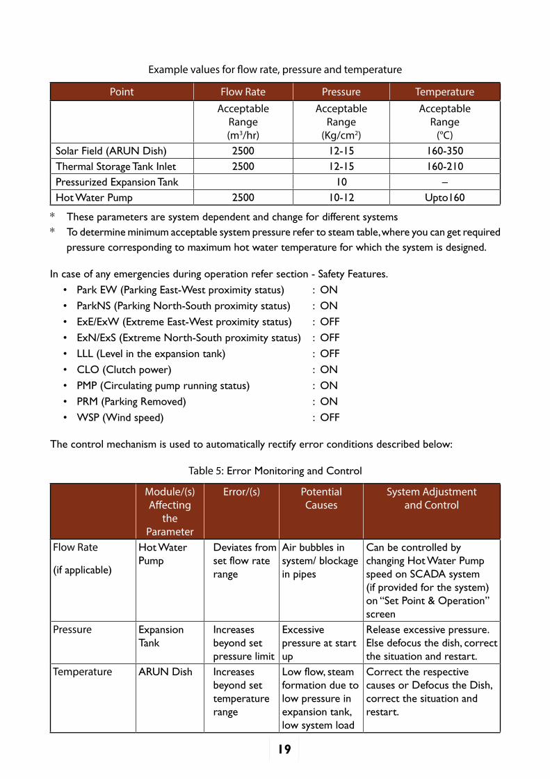
Example values for flow rate, pressure and temperature
Point Flow Rate Pressure Temperature
Acceptable Range(m3/hr)
Acceptable Range
(Kg/cm2)
Acceptable Range
(°C)Solar Field (ARUN Dish) 2500 12-15 160-350Thermal Storage Tank Inlet 2500 12-15 160-210Pressurized Expansion Tank 10 –Hot Water Pump 2500 10-12 Upto160
* These parameters are system dependent and change for different systems* To determine minimum acceptable system pressure refer to steam table, where you can get required
pressure corresponding to maximum hot water temperature for which the system is designed.
In case of any emergencies during operation refer section - Safety Features.
• Park EW (Parking East-West proximity status) : ON
• ParkNS (Parking North-South proximity status) : ON
• ExE/ExW (Extreme East-West proximity status) : OFF
• ExN/ExS (Extreme North-South proximity status) : OFF
• LLL (Level in the expansion tank) : OFF
• CLO (Clutch power) : ON
• PMP (Circulating pump running status) : ON
• PRM (Parking Removed) : ON
• WSP (Wind speed) : OFF
The control mechanism is used to automatically rectify error conditions described below:
Table 5: Error Monitoring and Control
Module/(s) Affecting
the Parameter
Error/(s) Potential Causes
System Adjustment and Control
Flow Rate
(if applicable)
Hot Water Pump
Deviates from set flow rate range
Air bubbles in system/ blockage in pipes
Can be controlled by changing Hot Water Pump speed on SCADA system (if provided for the system) on“SetPoint&Operation”screen
Pressure Expansion Tank
Increases beyond set pressure limit
Excessive pressure at start up
Release excessive pressure.Else defocus the dish, correct the situation and restart.
Temperature ARUN Dish Increases beyond set temperature range
Low flow, steam formation due to low pressure in expansion tank, low system load
Correct the respective causes or Defocus the Dish, correct the situation and restart.
20
4.4 Exceptions and Backup• Temperature of Thermic Fluid increases above set temperature• When temperature of thermic fluid crosses set temperature limit, Arun Dish
automatically defocuses from the receiver
• Power FailureTracking System has a ~ 45 minute power backup UPS to handle power cut which defocuses the dish during power cut.
• Storm / High Winds3 Cup Anemometer measures the wind velocity. Upper limit for wind is set to 10 m/s. Above this limit, Arun Dish goes in Parking Positionto protect it from structural damage.
• Not Using System for Long TimeKeep the dish secured in Parking Position
If circulation system contains water and atmospheric temperature reaches below freezing temperature, drain out water
If circulation system contains oil and atmospheric temperature reaches below pour point of oil, drain outoil into appropriate storage.
4.5 Shutdown SequenceFollow the following sets of actions to shutdown Arun Dish System:
1. When the dish reaches near sunset position, it will automatically enter the parking mode and thedishwillbebroughttoparkingposition.Alsoonecanselect‘ParkingMode’forthesameoperation.
2. When it gets parking on both axes (sensed from the parking proximity switches), the dish will stop.Thiscanbeseenoncontrollerwhenit’sLEDglowsgreenorevenseeninInputStatus.
3. Now engage all the parking sturts. (If parking sturts do not match properly then move the dish forward/reverse by selecting manual mode. (Ref. manual mode selection instructions to oper-ate the dish in manual mode)).
4. Now switch OFF circulating and make up water pumps.
5. Switch OFF the main electrical panel.
6. Record the flow meter reading to know the quantity of steam delivered
7. Close the outlet valve on steam delivery line.
8. At the end, open the by-pass valve of steam trap to avoid vacuum formation
4.6 Shutdown Sequence in Manual Mode1. Repeat steps 1-7 of section 1.2
2. Now select Manual mode by Auto/Manual selector switch on the controller.
3. Use FWD-REV push buttons on the controller to rotate the dish as desired.
4. There are two sets of FWD-REV buttons on the controller for each axis respectively.
5. Press both Buttons simultaneously to stop the motor
NOTE: FWD for vertical motor: towards WEST, REV for vertical motor: towards EAST, FWD for horizontal motor: towards SOUTH, REV for horizontal motor: towards NORTH
21
5.0 Maintenance
5.1 Predictive MaintenanceThe system is designed to provide easy isolation for maintenance or emergency repairs. To isolate any module, close down respective Gate Valves for it and do the maintenance.
You can contribute to trouble-free and reliable performance of your solar system by regularlyperforming following checks to determine whether maintenance is required or not:
• Annually, check for scaling at inner linings of Circulation System.
Scalinganditseffectonsystem’sperformancehastobevisuallydetermined.
This maintenance task is generally outsourced because it is rarely performed and requires descaler systems and industrial descaling chemicals
• Quarterly, check for pressure at nitrogen cylinder - Whenever pressure in N2 cylinder dropsbe-
low 26 Kg/cm2 replace it
• Weekly, check for leakages in the system. Perform this operation when you spot leakages in circulation line
Identify the point of leakage and remove insulation for that component
Repair/Replace component with leakage
Leave insulation material (mineral wool) open to dry off, and then put it back
• Annually, inspect Sensors in the System
Level Transmitter (Ultrasonic/DP Type): Check connection and tightness of wiring. Clean Level Transmitter
RTD and Thermowell: Check connection and tightness of wiring. Check oil and fill if required
Pressure/Temperature Transmitter: Check connection and tightness of wiring
• Annually, check pressureat output of safety relief valve and adjust it to required set pressure
• Half yearly, inspect solenoid valves
Check their operation, overheating during operations
Clean the valves
• Weekly, Check Dish Tracking Mechanism-Dish Motors, Gear Box, Sprockets, Shafts, Bushes
Check oiling and greasing
Check for vibration and noise
Check for heating problem and tighten loose parts
Replace bearing if required
• Monthly check for functioning of Dosing Systems
Check for leakage of hazardous substances
Clean and rinse the pump
Check for screwed connections of piping and containers, and tighten if necessary
Carry out a visual inspection of pressure test
Check for electrical lines and components for visible damages (loose connections, damaged cables, etc.)
22
5.2 Preventive MaintenanceFollowing preventive maintenance must be undertaken as per schedule to avoid system failures to get trouble-free and reliable performance:
• Weekly, lubricate chain block pulley with grease/oil, but not too much as that will attract dust. Lubrication should be done specially after rainy season
• Monthly, replace water in circulation system with fresh soft water from RO system
Note: If thermic fluid/oil is used in circulation system don’t clean with water; either usecompressed air, or flush fluid from the tank to clean piping system
• Annually, undertake structural painting and repair of the dish to improve life span of the system
• Annually, replace soft water resin in RO water purifier
• In every three years, clean pressurized expansion tanks
Preventive maintenance of the Arun Dishes improves efficiency and reliability of the system. Maintenance period is based on measured values from Solar System Data Log. Data Log helps the trained service technician to identify and troubleshoot any potential problems with in a system.
5.3 Consumable ReplacementFollowing are the consumable parts in the system which needs standby stock:
• Nitrogen cylinder (Optional)
• Gaskets(sizeaspermanufacturer’sspecifications)
• Teflon Tape
• Lubricant Oil and Grease
Note: Please refer to manufacturer for recommended consumable item specifications.
5.4 Routine MaintenanceThe system requires some simple and small-scale activities for general upkeep of the system. The following tasks must be regularly performed when using the system:
• Weekly, clean Arun Dish System
Use parking locks to lock the ladder.
Climb up use Sprayer to wipe of dust
Clean the Dish in early morning before starting the system
• Weekly, dust off the Pyrometer with a dry soft cloth
• Monthly,cleanScreeninY-Strainerswithbrushorbysoakingitinacleansolution
• Twice a year, clean RO system Cartridge Filler
For module wise maintenance activity schedule refer to Appendix 4.
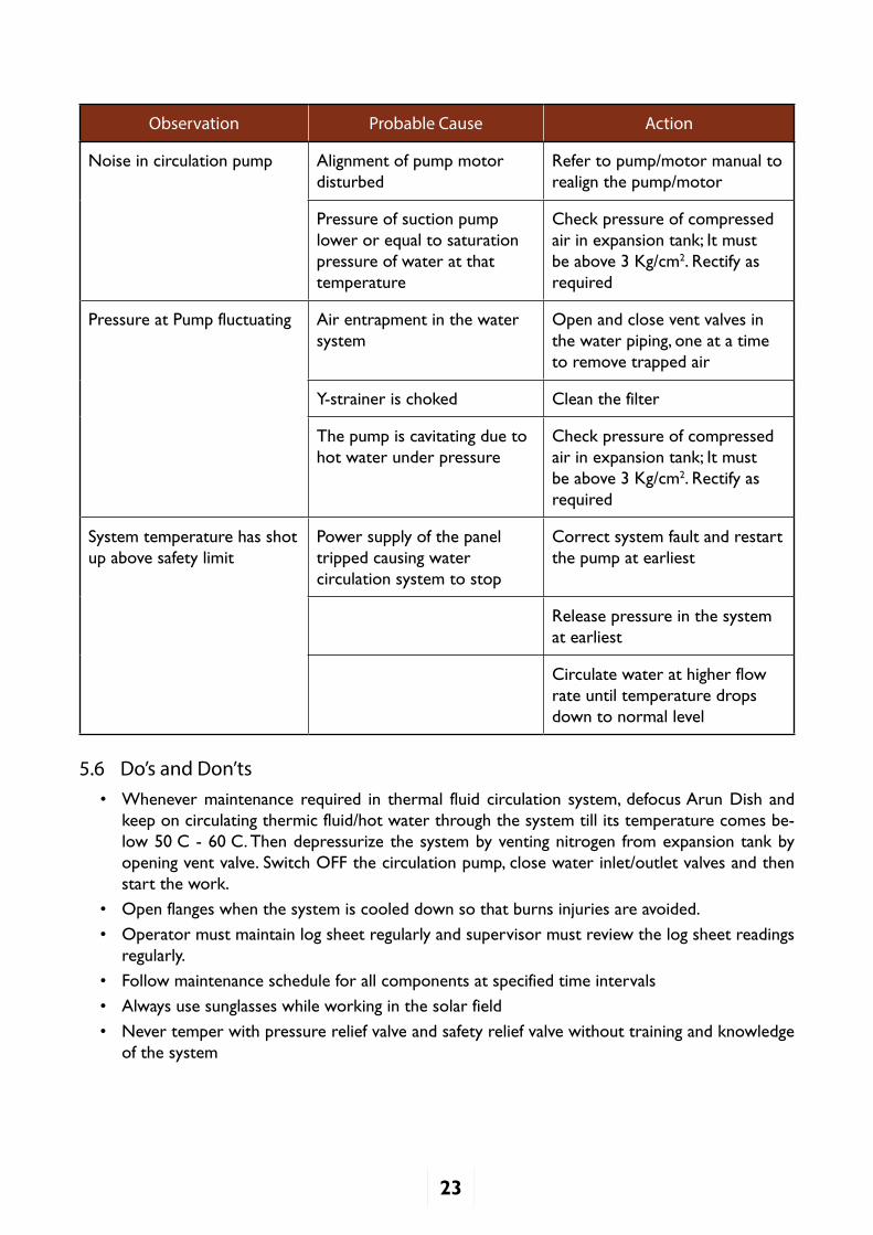
5.5 Troubleshooting
A few process related troubleshooting points are given below. Refer to respective manual for troubleshooting of components:
23
Observation Probable Cause Action
Noise in circulation pump Alignment of pump motor disturbed
Refer to pump/motor manual to realign the pump/motor
Pressure of suction pump lower or equal to saturation pressure of water at that temperature
Check pressure of compressed airinexpansiontank;Itmustbe above 3 Kg/cm2. Rectify as required
Pressure at Pump fluctuating Air entrapment in the water system
Open and close vent valves in the water piping, one at a time to remove trapped air
Y-strainerischoked Clean the filter
The pump is cavitating due to hot water under pressure
Check pressure of compressed airinexpansiontank;Itmustbe above 3 Kg/cm2. Rectify as required
System temperature has shot up above safety limit
Power supply of the panel tripped causing water circulation system to stop
Correct system fault and restart the pump at earliest
Release pressure in the system at earliest
Circulate water at higher flow rate until temperature drops down to normal level
5.6 Do’s and Don’ts• Whenever maintenance required in thermal fluid circulation system, defocus Arun Dish and
keep on circulating thermic fluid/hot water through the system till its temperature comes be-low50°C-60°C.Thendepressurizethesystembyventingnitrogen fromexpansiontankbyopening vent valve. Switch OFF the circulation pump, close water inlet/outlet valves and then start the work.
• Open flanges when the system is cooled down so that burns injuries are avoided.
• Operator must maintain log sheet regularly and supervisor must review the log sheet readings regularly.
• Follow maintenance schedule for all components at specified time intervals
• Always use sunglasses while working in the solar field
• Never temper with pressure relief valve and safety relief valve without training and knowledge of the system
24
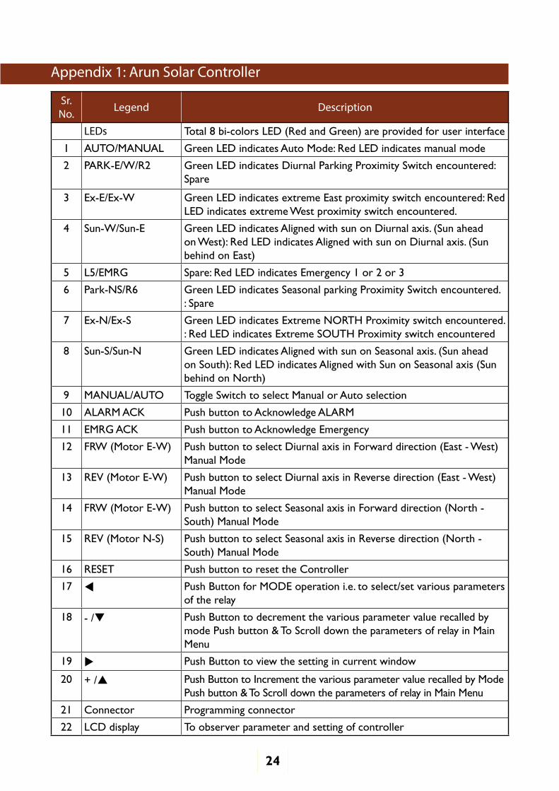
Appendix 1: Arun Solar Controller
Sr. No. Legend Description
LEDs Total 8 bi-colors LED (Red and Green) are provided for user interface
1 AUTO/MANUAL Green LED indicates Auto Mode: Red LED indicates manual mode
2 PARK-E/W/R2 Green LED indicates Diurnal Parking Proximity Switch encountered: Spare
3 Ex-E/Ex-W Green LED indicates extreme East proximity switch encountered: Red LED indicates extreme West proximity switch encountered.
4 Sun-W/Sun-E Green LED indicates Aligned with sun on Diurnal axis. (Sun ahead on West): Red LED indicates Aligned with sun on Diurnal axis. (Sun behind on East)
5 L5/EMRG Spare: Red LED indicates Emergency 1 or 2 or 3
6 Park-NS/R6 Green LED indicates Seasonal parking Proximity Switch encountered. : Spare
7 Ex-N/Ex-S Green LED indicates Extreme NORTH Proximity switch encountered. : Red LED indicates Extreme SOUTH Proximity switch encountered
8 Sun-S/Sun-N Green LED indicates Aligned with sun on Seasonal axis. (Sun ahead on South): Red LED indicates Aligned with Sun on Seasonal axis (Sun behind on North)
9 MANUAL/AUTO Toggle Switch to select Manual or Auto selection
10 ALARM ACK Push button to Acknowledge ALARM
11 EMRG ACK Push button to Acknowledge Emergency
12 FRW (Motor E-W) Push button to select Diurnal axis in Forward direction (East - West) Manual Mode
13 REV (Motor E-W) Push button to select Diurnal axis in Reverse direction (East - West) Manual Mode
14 FRW (Motor E-W) Push button to select Seasonal axis in Forward direction (North - South) Manual Mode
15 REV (Motor N-S) Push button to select Seasonal axis in Reverse direction (North - South) Manual Mode
16 RESET Push button to reset the Controller
17 Push Button for MODE operation i.e. to select/set various parameters of the relay
18 - / Push Button to decrement the various parameter value recalled by mode Push button & To Scroll down the parameters of relay in Main Menu
19 Push Button to view the setting in current window
20 + / Push Button to Increment the various parameter value recalled by Mode Push button & To Scroll down the parameters of relay in Main Menu
21 Connector Programming connector
22 LCD display To observer parameter and setting of controller
25
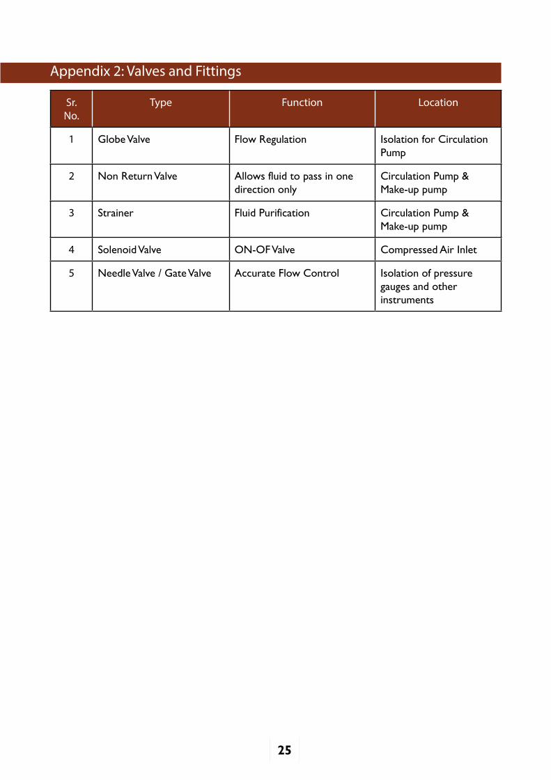
Appendix 2: Valves and Fittings
Sr. No.
Type Function Location
1 Globe Valve Flow Regulation Isolation for Circulation Pump
2 Non Return Valve Allows fluid to pass in one direction only
Circulation Pump & Make-up pump
3 Strainer Fluid Purification Circulation Pump & Make-up pump
4 Solenoid Valve ON-OF Valve Compressed Air Inlet
5 Needle Valve / Gate Valve Accurate Flow Control Isolation of pressure gauges and otherinstruments
26
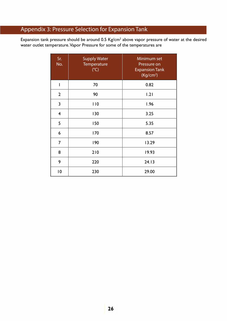
Appendix 3: Pressure Selection for Expansion Tank
Expansion tank pressure should be around 0.5 Kg/cm2 above vapor pressure of water at the desired water outlet temperature. Vapor Pressure for some of the temperatures are
Sr. No.
Supply WaterTemperature
(°C)
Minimum set Pressure on
Expansion Tank(Kg/cm2)
1 70 0.82
2 90 1.21
3 110 1.96
4 130 3.25
5 150 5.35
6 170 8.57
7 190 13.29
8 210 19.93
9 220 24.13
10 230 29.00
27
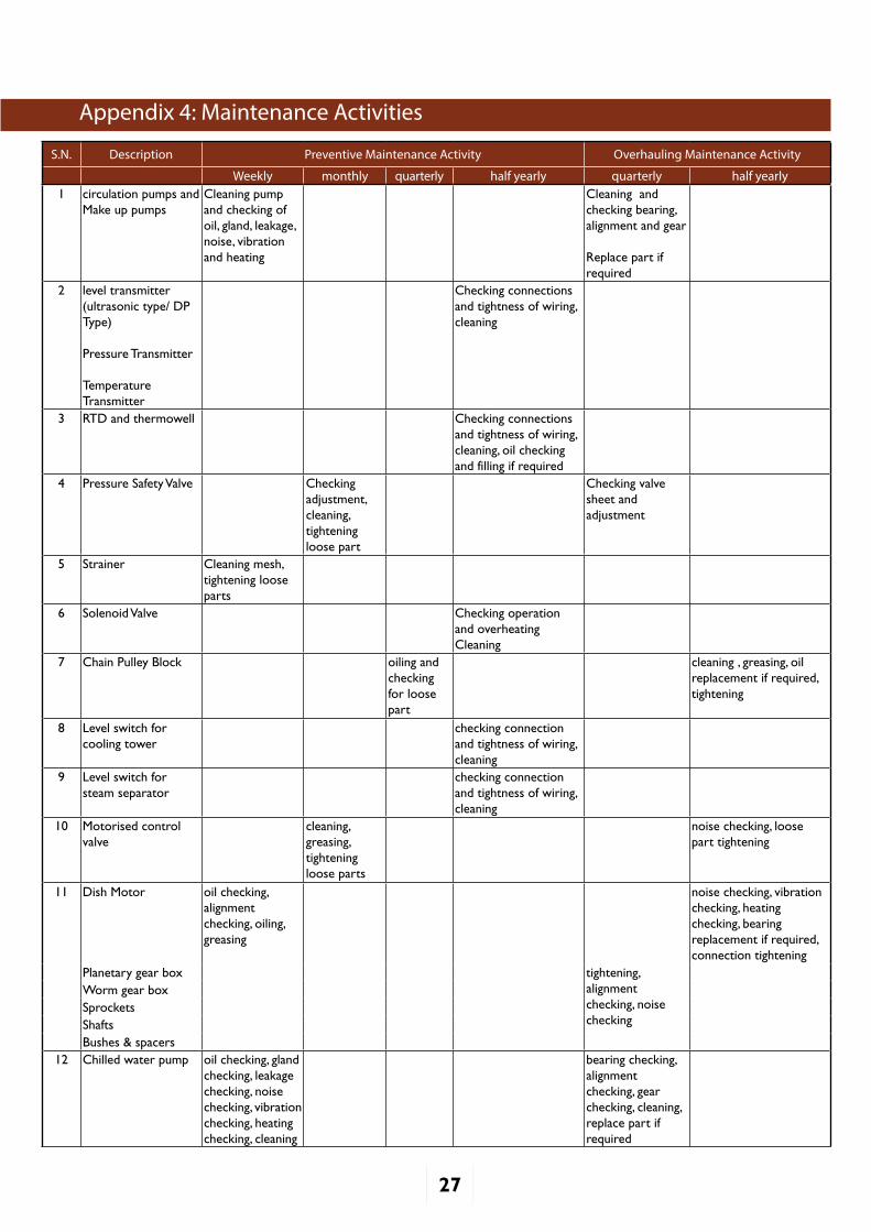
S.N. Description Preventive Maintenance Activity Overhauling Maintenance Activity
Weekly monthly quarterly half yearly quarterly half yearly1 circulation pumps and
Make up pumpsCleaning pump and checking of oil, gland, leakage, noise, vibration and heating
Cleaning and checking bearing, alignment and gear
Replace part if required
2 level transmitter (ultrasonic type/ DP Type)
Pressure Transmitter
Temperature Transmitter
Checking connections and tightness of wiring, cleaning
3 RTD and thermowell Checking connections and tightness of wiring, cleaning, oil checking and filling if required
4 Pressure Safety Valve Checking adjustment, cleaning, tightening loose part
Checking valve sheet and adjustment
5 Strainer Cleaning mesh, tightening loose parts
6 Solenoid Valve Checking operation and overheatingCleaning
7 Chain Pulley Block oiling and checking for loose part
cleaning , greasing, oil replacement if required, tightening
8 Level switch for cooling tower
checking connection and tightness of wiring, cleaning
9 Level switch for steam separator
checking connection and tightness of wiring, cleaning
10 Motorised control valve
cleaning, greasing, tightening loose parts
noise checking, loose part tightening
11 Dish Motor oil checking, alignment checking, oiling, greasing
noise checking, vibration checking, heating checking, bearing replacement if required, connection tightening
Planetary gear box tightening, alignment checking, noise checking
Worm gear box Sprockets Shafts Bushes & spacers
12 Chilled water pump oil checking, gland checking, leakage checking, noise checking, vibration checking, heating checking, cleaning
bearing checking, alignment checking, gear checking, cleaning, replace part if required
Appendix 4: Maintenance Activities
28
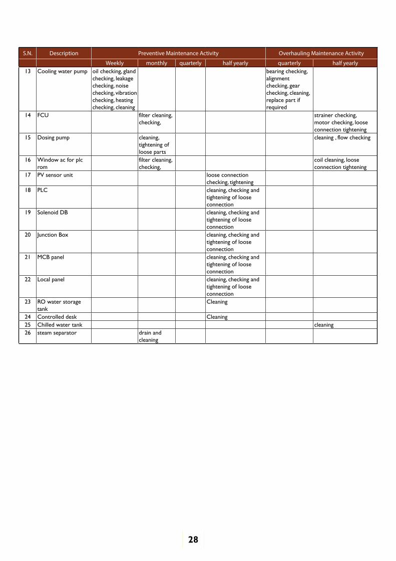
S.N. Description Preventive Maintenance Activity Overhauling Maintenance Activity
Weekly monthly quarterly half yearly quarterly half yearly13 Cooling water pump oil checking, gland
checking, leakage checking, noise checking, vibration checking, heating checking, cleaning
bearing checking, alignment checking, gear checking, cleaning, replace part if required
14 FCU filter cleaning, checking,
strainer checking, motor checking, loose connection tightening
15 Dosing pump cleaning, tightening of loose parts
cleaning , flow checking
16 Window ac for plc rom
filter cleaning, checking,
coil cleaning, loose connection tightening
17 PV sensor unit loose connection checking, tightening
18 PLC cleaning, checking and tightening of loose connection
19 Solenoid DB cleaning, checking and tightening of loose connection
20 Junction Box cleaning, checking and tightening of loose connection
21 MCB panel cleaning, checking and tightening of loose connection
22 Local panel cleaning, checking and tightening of loose connection
23 RO water storage tank
Cleaning
24 Controlled desk Cleaning 25 Chilled water tank cleaning26 steam separator drain and
cleaning
29
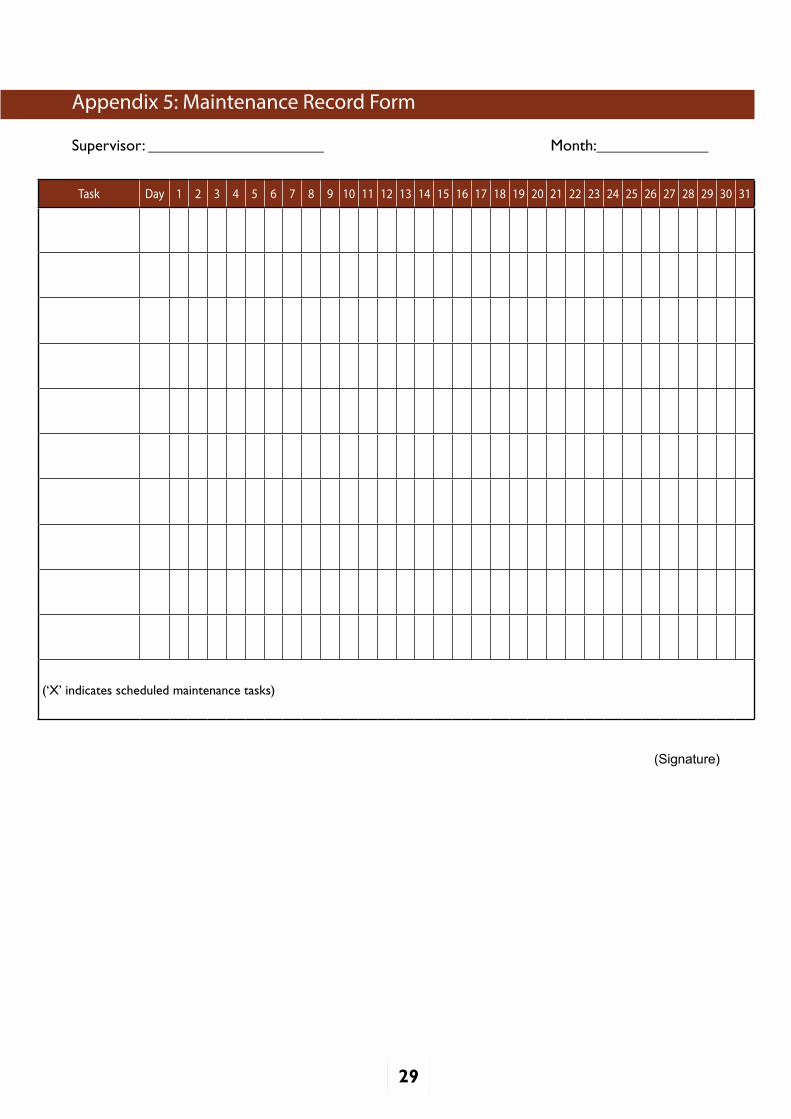
Task Day 1 2 3 4 5 6 7 8 9 10 11 12 13 14 15 16 17 18 19 20 21 22 23 24 25 26 27 28 29 30 31
(‘X’indicatesscheduledmaintenancetasks)
Appendix 5: Maintenance Record Form
Supervisor: ______________________ Month:______________
(Signature)
30
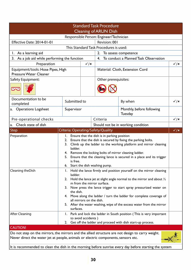
Standard Task ProcedureCleaning of ARUN Dish
Responsible Person: Engineer/TechnicianEffective Date: 2014-01-01 Revision: 001
This Standard Task Procedures is used:1. As a learning aid 2. To assess competence3. As a job aid while performing the function 4. To conduct a Planned Task Observation
Preparation / /Equipment/tools: Hose Pipes, High Pressure Water Cleaner
Material: Cloth, Extension Cord
Safety Equipment: Other prerequisites:
Documentation to be completed Submitted to By when /
a. Operations Logsheet Supervisor Monthly, before following Tuesday
Pre-operational checks Criteria /a. Check state of dish Should not be in working conditionStep Criteria: Operating/Safety/Quality /Preparation 1. Ensure that the dish is in parking position
2. Ensure that the dish is secured by fixing the parking bolts. 3. Climb up the ladder to the working platform and mirror cleaning
ladder.4. Remove the locking bolts of mirror cleaning ladder. 5. Ensure that the cleaning lance is secured in a place and its trigger
is free.6. Start the dish washing pump.
Cleaning theDish 1. Hold the lance firmly and position yourself on the mirror cleaning ladder.
2. Holdthelancejetatslightanglenormaltothemirrorandabout½m from the mirror surface.
3. Now press the lance trigger to start spray pressurized water on the dish.
4. Move along the ladder / turn the ladder for complete coverage of all mirrors on the dish.
5. After the water washing, wipe of the excess water from the mirror surfaces.
After Cleaning 1. Park and lock the ladder in South position ( This is very important to avoid accidents )
2. Get off the ladder and proceed with dish start-up process.
CAUTION!Do not step on the mirrors, the mirrors and the allied structure are not design to carry weight.Never direct the water jet at people, animals or electric components, sensors etc.
It is recommended to clean the dish in the morning before sunrise every day before starting the system

Prepared by
D-66, 60 Feet Road, First Floor (Above Corporation Bank), Near Chattarpur Temple, New Delhi - 110074 Email: [email protected] Website: www.anthropower.in