Embed Size (px)
Citation preview
29
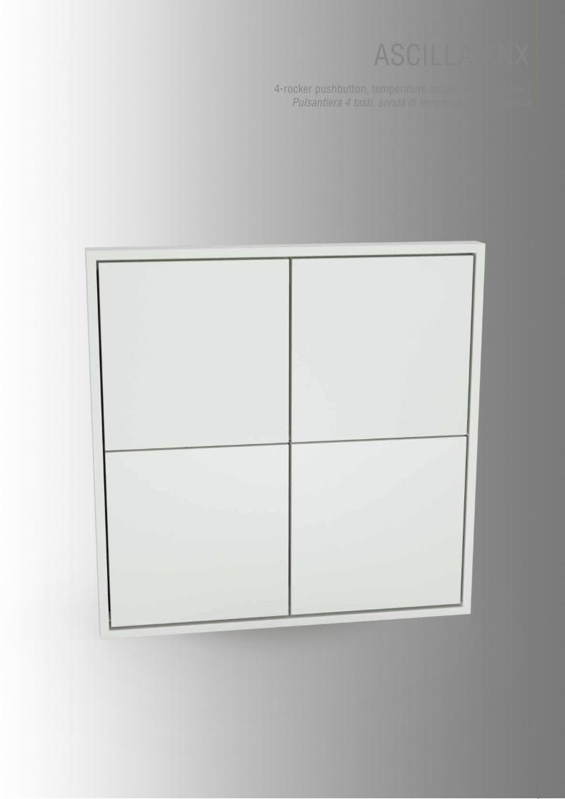
ASCILLA KNX4-rocker pushbutton, temperature and brightness probe /
Pulsantiera 4 tasti, sonda di temperatura e luminosità
30
DATASHEET /SCHEDE TECNICHE
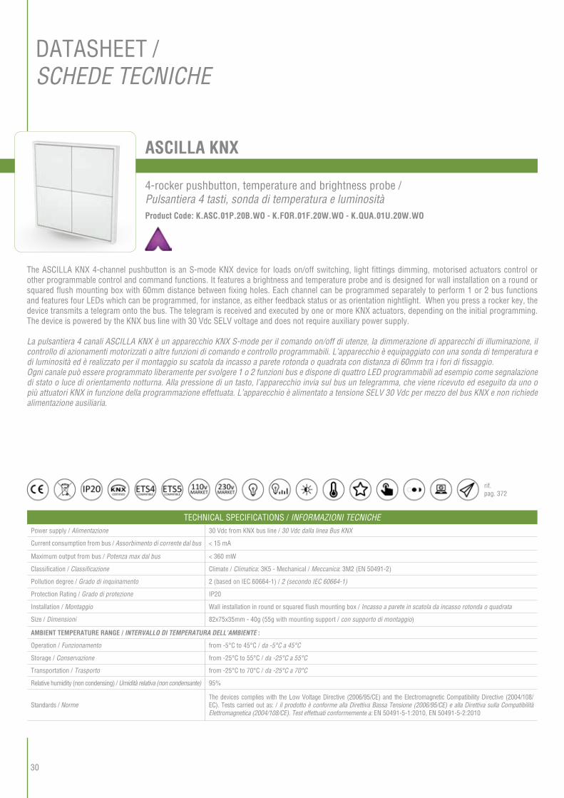
ASCILLA KNX
TECHNICAL SPECIFICATIONS / INFORMAZIONI TECNICHEPower supply / Alimentazione 30 Vdc from KNX bus line / 30 Vdc dalla linea Bus KNX
Current consumption from bus / Assorbimento di corrente dal bus < 15 mA
Maximum output from bus / Potenza max dal bus < 360 mW
Classification / Classificazione Climate / Climatica: 3K5 - Mechanical / Meccanica: 3M2 (EN 50491-2)
Pollution degree / Grado di inquinamento 2 (based on IEC 60664-1) / 2 (secondo IEC 60664-1)
Protection Rating / Grado di protezione IP20
Installation / Montaggio Wall installation in round or squared flush mounting box / Incasso a parete in scatola da incasso rotonda o quadrata
Size / Dimensioni 82x75x35mm - 40g (55g with mounting support / con supporto di montaggio)
AMBIENT TEMPERATURE RANGE / INTERVALLO DI TEMPERATURA DELL’AMBIENTE :
Operation / Funzionamento from -5°C to 45°C / da -5°C a 45°C
Storage / Conservazione from -25°C to 55°C / da -25°C a 55°C
Transportation / Trasporto from -25°C to 70°C / da -25°C a 70°C
Relative humidity (non condensing) / Umidità relativa (non condensante) 95%
Standards / NormeThe devices complies with the Low Voltage Directive (2006/95/CE) and the Electromagnetic Compatibility Directive (2004/108/EC). Tests carried out as: / il prodotto è conforme alla Direttiva Bassa Tensione (2006/95/CE) e alla Direttiva sulla Compatibilità Elettromagnetica (2004/108/CE). Test effettuati conformemente a: EN 50491-5-1:2010, EN 50491-5-2:2010
The ASCILLA KNX 4-channel pushbutton is an S-mode KNX device for loads on/off switching, light fittings dimming, motorised actuators control or other programmable control and command functions. It features a brightness and temperature probe and is designed for wall installation on a round or squared flush mounting box with 60mm distance between fixing holes. Each channel can be programmed separately to perform 1 or 2 bus functions and features four LEDs which can be programmed, for instance, as either feedback status or as orientation nightlight. When you press a rocker key, the device transmits a telegram onto the bus. The telegram is received and executed by one or more KNX actuators, depending on the initial programming. The device is powered by the KNX bus line with 30 Vdc SELV voltage and does not require auxiliary power supply.
La pulsantiera 4 canali ASCILLA KNX è un apparecchio KNX S-mode per il comando on/off di utenze, la dimmerazione di apparecchi di illuminazione, il controllo di azionamenti motorizzati o altre funzioni di comando e controllo programmabili. L’apparecchio è equipaggiato con una sonda di temperatura e di luminosità ed è realizzato per il montaggio su scatola da incasso a parete rotonda o quadrata con distanza di 60mm tra i fori di fissaggio.Ogni canale può essere programmato liberamente per svolgere 1 o 2 funzioni bus e dispone di quattro LED programmabili ad esempio come segnalazione di stato o luce di orientamento notturna. Alla pressione di un tasto, l’apparecchio invia sul bus un telegramma, che viene ricevuto ed eseguito da uno o più attuatori KNX in funzione della programmazione effettuata. L’apparecchio è alimentato a tensione SELV 30 Vdc per mezzo del bus KNX e non richiede alimentazione ausiliaria.
Product Code: K.ASC.01P.20B.WO - K.FOR.01F.20W.WO - K.QUA.01U.20W.WO
4-rocker pushbutton, temperature and brightness probe / Pulsantiera 4 tasti, sonda di temperatura e luminosità
rif. pag. 372
31
FEATURES- On/off switching of loads (individually or groups)- Dimming of light fittings- Control of motorised actuators (shutters, blinds with one or two programmable buttons)- Scenes recalling and saving- Transmission of values onto the bus (temperature, brightness, etc.)- Switching to forced operation (lock)- Measuring of temperature and light brightness in the room with integrated sensors (offset adjustment and cyclical transmission, brightness adjustment, two programmable thresholds)- Different functions programmable by short-/long-pressing a rocker key- Simultaneous sending of up to 8 settable values per key
CARATTERISTICHE- Comando On/OFF di utenze elettriche singole e a gruppi- Dimmerazione di apparecchi di illuminazione- Controllo di motorizzazioni (tapparelle, tende con uno o due tasti impostabili)- Richiamo e memorizzazione di scenari- Invio di valori sul Bus (temperature, luminosità, etc.)- Commutazione a funzionamento forzato (lock)- Rilevamento della luminosità e della temperatura ambiente mediante sensori integrati (regolazione offset ed invio ciclico, taratura luminosità, due soglie impostabili)- Differenti funzioni programmabili per pressione breve/pressione prolungata di un tasto- Invio simultaneo per ogni pulsante fino ad 8 valori impostabili
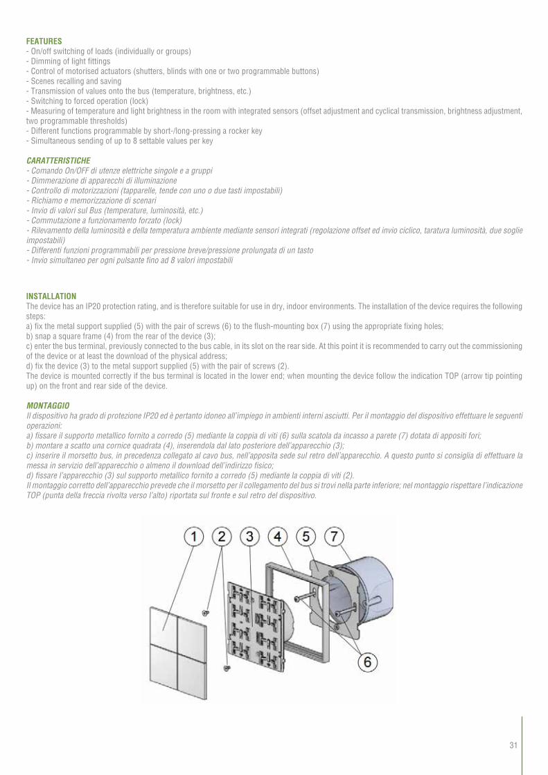
INSTALLATIONThe device has an IP20 protection rating, and is therefore suitable for use in dry, indoor environments. The installation of the device requires the following steps:a) fix the metal support supplied (5) with the pair of screws (6) to the flush-mounting box (7) using the appropriate fixing holes;b) snap a square frame (4) from the rear of the device (3);c) enter the bus terminal, previously connected to the bus cable, in its slot on the rear side. At this point it is recommended to carry out the commissioning of the device or at least the download of the physical address;d) fix the device (3) to the metal support supplied (5) with the pair of screws (2).The device is mounted correctly if the bus terminal is located in the lower end; when mounting the device follow the indication TOP (arrow tip pointing up) on the front and rear side of the device.
MONTAGGIOIl dispositivo ha grado di protezione IP20 ed è pertanto idoneo all’impiego in ambienti interni asciutti. Per il montaggio del dispositivo effettuare le seguenti operazioni:a) fissare il supporto metallico fornito a corredo (5) mediante la coppia di viti (6) sulla scatola da incasso a parete (7) dotata di appositi fori;b) montare a scatto una cornice quadrata (4), inserendola dal lato posteriore dell’apparecchio (3);c) inserire il morsetto bus, in precedenza collegato al cavo bus, nell’apposita sede sul retro dell’apparecchio. A questo punto si consiglia di effettuare la messa in servizio dell’apparecchio o almeno il download dell’indirizzo fisico;d) fissare l’apparecchio (3) sul supporto metallico fornito a corredo (5) mediante la coppia di viti (2). Il montaggio corretto dell’apparecchio prevede che il morsetto per il collegamento del bus si trovi nella parte inferiore; nel montaggio rispettare l’indicazione TOP (punta della freccia rivolta verso l’alto) riportata sul fronte e sul retro del dispositivo.

34
SWITCHING AND CONNECTION ELEMENTSThe device is equipped with 4 for independent switching mechanisms, 2 programmable LEDs per channel, a programming LED and a programming button.Switching elements:- Button (3) for switching between normal and programming operating mode- Mechanisms (4) for independent switching of loads (individual or groups) to be completed with square or rectangular rocker keys- Red LED (2) to signal active operating mode (on = programming, off = normal operation)- Freely programmable white and red LEDs; e.g. for controlled loads feedback status and orientation nightlight
ELEMENTI DI COMANDO E CONNESSIONEIl dispositivo è dotato di quattro meccanismi per l’azionamento indipendente, di due LED programmabili per ogni canale, di un pulsante e di un LED di programmazione.Elementi di comando:- Pulsante (3) per la commutazione fra le modalità di funzionamento normale e programmazione - Meccanismi (4) per il comando indipendente dei gruppi di utenze da completare mediante tasti quadrati o rettangolari - LED rosso (2) per l’indicazione della modalità attiva (acceso = programmazione, spento = funzionamento normale) - LED bianchi e rossi liberamente programmabili; e.s. per segnalazione di stato delle utenze comandate e per luce di orientamento notturna
1) Connection terminal block for KNX bus line / Morsetto di connessione per linea KNX2) Programming LED / LED di Programmazione3) Programming button / Pulsante di programmazione4) Rocker keys housing (e.g.: square rocker 40x40 mm) / Alloggio per montaggio dei pulsanti (ad esempio: tasti quadrati 40x40 mm)5) LED Guide Light / Luce guida per LED

35
CONNECTION OF THE KNX BUS LINEThe device is connected to the KNX bus line using the (black/red) terminal block supplied and inserted into the slot on the rear side of the device housing.KNX terminal block features:- spring clamping of conductors- 4 conductor seats per polarity- terminal suitable for KNX bus cable with single-wire conductors and diameter between 0.6 and 0.8 mm- recommended wire stripping approx. 5 mm- colour code: red = + (positive) bus conductor, black = - (negative)bus conductor.
CONNESSIONE DELLA LINEA BUS KNXIl collegamento alla rete bus avviene mediante il morsetto KNX compreso nella fornitura e inserito nell’apposito alloggiamento situato sul retro del dispositivo.Caratteristiche del morsetto KNX:- Serraggio a molla dei conduttori - 4 sedi conduttore per ogni polarità - Idoneo per cavo bus KNX con conduttore unifilari di diametro compreso fra 0.6 e 0.8 mm - Spellatura conduttore consigliata. 5 mm - Codifica colori: rosso = + conduttore bus (positivo), nero = - conduttore bus (negativo).
CONFIGURATION AND COMMISSIONINGConfiguration and commissioning of the device require the use of the ETS® (Engineering Tool Software) program V4 or later releases. These activities must be carried out according to the building automation system design done by a qualified planner.Commissioning:Commissioning of the device requires the following activities:- make the electrical connections as described above;- switch the bus supply voltage on;- switch the device operation mode to programming mode by pressing the programming button located on the back of the device. In this operation mode the programming LED is on;- download physical address and configuration to the device with the ETS® program. Once the download is complete, the deviceautomatically switches back to normal mode; in this mode the programming LED is turned off. The bus device is now programmed and ready for use.
CONFIGURAZIONE E MESSA IN SERVIZIO La configurazione e la messa in servizio del dispositivo richiedono l’utilizzo del programma ETS® (Engineering Tool Software) V4 o versioni successive. Queste attività devono essere effettuate in conformità al progetto dell’impianto di automazione dell’edificio realizzato a cura di un professionista abilitato.Messa in servizio:Per la messa in servizio dell’apparecchio sono necessarie le seguenti attività: - eseguire I collegamenti elettrici come indicato sopra; - dare tensione al bus; - commutare il funzionamento del dispositivo in modalità di programmazione premendo l’apposito pulsante situato sul retro dell’apparecchio. In questa modalità di funzionamento il LED di programmazione è acceso; - scaricare nel dispositivo l’indirizzo fisico e la configurazione mediante il programma ETS®. Al termine del download il funzionamento dell’apparecchio ritorna automaticamente in modalità normale; in questa modalità di funzionamento il LED di programmazione è spento. L’apparecchio bus è programmato e pronto al funzionamento.
CONNECTION DIAGRAM / SCHEMA DI COLLEGAMENTO

36
PUSHBUTTON COMBINABLE WITH FRAME / TIPOLOGIA PULSANTIERA ABBINABILE A CORNICEBelow a list of the available types of pushbuttons combinable with frame / A seguito sono indicati i tipi di pulsantiera disponibili abbinabili a cornice.
FRAMELESS PUSHBUTTON / TIPOLOGIA PULSANTIERA SENZA CORNICEBelow a list of the frameless pushbuttons available / A seguito sono indicati i tipi di pulsantiera disponibili senza cornice.
FINISHES / FINITUREBelow a list of the colours available for Vivo Ascilla KNX pushbutton / A seguito sono indicati i colori della pulsantiera Vivo Ascilla KNX.
Pure White - StandardBianco Puro - Standard
Pure White - Soft TouchBianco Puro - Soft Touch
Black - StandardNero - Standard
Silver Grey / Grigio argento
Aluminum / Alluminio
Metal finishes / Finiture in Metallo
Plastic finishes / Finiture in Plastica
ASCILLA FRAMECod. K.ASC.01P.20B.WO
ASCILLA NO FRAME BLACKCod. K.ASC.02P.20B.WO
ASCILLA NO FRAME WHITECod. K.ASC.02P.20W.WO
Black - Soft TouchNero - Soft Touch
Hematite / Ematite
Nickel / Nichel
Graphite / Grafite
Titanium / Titanio Carbon / Carbonio

37
FRAME COLOURS / COLORAZIONE CORNICIBelow a list of the colours and relative codes for the plastic and metal frames available /A seguito sono indicati i colori con relativi codici delle cornici disponibili in plastica e metallo
Pure White - StandardBianco Puro - StandardCod. K.FOR.01F.20W.WO
Standard BlackNero StandardCod. K.FOR.01F.20B.WO
Aluminum / AlluminioCod. K.FOR.01F.21A.WO
Silver Grey / Grigio argentoCod. K.FOR.01F.20G.WO
Nickel / NichelCod. K.FOR.01F.21D.WO
Hematite / EmatiteCod. K.FOR.01F.20H.WO
Titanium / TitanioCod. K.FOR.01F.21E.WO
Carbon / CarbonioCod. K.FOR.01F.21F.WO
Graphite / GrafiteCod. K.FOR.01F.20C.WO
Cod. K.ASC.01P.20B.WO - K.FOR.01F.20C.WO - K.RIT.01U.20B.WO Cod. K.ASC.02P.20W.WO - K.RIT.01U.20W.WO
Metal finishes / Finiture in Metallo
Plastic finishes / Finiture in Plastica

38
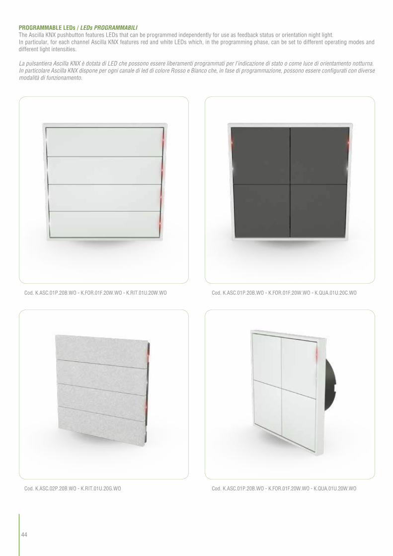
Cod. K.ASC.01P.20B.WO - K.FOR.01F.20W.WO - K.QUA.01U.20C.WO Cod. K.ASC.01P.20B.WO - K.FOR.01F.20B.WO - K.QUA.02U.20W.WO
Cod. K.ASC.02P.20W.WO - K.QUA.01U.20W.WO
Cod. K.ASC.02P.20W.WO - K.RIT.01U.20W.WO
Cod. K.ASC.02P.20B.WO - K.QUA.01U.20G.WO
Cod. K.ASC.02P.20B.WO - K.RIT.01U.20G.WO
Cod. K.ASC.02P.20B.WO - K.QUA.01U.20B.WO
Cod. K.ASC.02P.20B.WO - K.RIT.01U.20B.WO
Here are a few examples / A seguito alcuni esempi:

40
SQUARE BUTTON COLOURS / COLORAZIONE PULSANTI QUADRATIBelow the colours of the square buttons available with relevant codes /A seguito sono indicati i colori con relativi codici dei pulsanti quadrati disponibili
Pure White - StandardBianco Puro - StandardCod. K.QUA.01U.20W.WO
Pure White - Soft TouchBianco Puro - Soft TouchCod. K.QUA.02U.20W.WO
Black - StandardNero - StandardCod. K.QUA.01U.20B.WO
Silver / ArgentoCod. K.QUA.01U.20G.WO
Black - Soft TouchNero - Soft TouchCod. K.QUA.02U.20B.WO
Hematite / EmatiteCod. K.QUA.01U.20H.WO
Graphite / GrafiteCod. K.QUA.01U.20C.WO
Cod. K.ASC.01P.20B.WO - K.FOR.01F.20W.WO - K.QUA.01U.20W.WO
Cod. K.ASC.01P.20B.WO - K.FOR.01F.20B.WO - K.QUA.01U.20B.WO
Cod. K.ASC.01P.20B.WO - K.FOR.01F.20C.WO - K.QUA.01U.20C.WO
Here are a few examples / A seguito alcuni esempi:
Aluminum / AlluminioCod. K.QUA.01U.21A.WO
Nickel / NichelCod. K.QUA.01U.21D.WO
Titanium / TitanioCod. K.QUA.01U.21E.WO
Carbon / CarbonioCod. K.QUA.01U.21F.WO
Metal finishes / Finiture in Metallo
Plastic finishes / Finiture in Plastica

41
RECTANGULAR BUTTON COLOURS / COLORAZIONE PULSANTI RETTANGOLARIFollowing are indicated the colors of the available rectangle buttons / A seguito sono indicati i colori con relativi codici dei pulsanti rettangolari disponibili
Pure White - StandardBianco Puro - StandardCod. K.RIT.01U.20W.WO
Pure White - Soft TouchBianco Puro - Soft TouchCod. K.RIT.02U.20W.WO
Black - StandardNero - StandardCod. K.RIT.01U.20B.WO
Silver / ArgentoCod. K.RIT.01U.20G.WO
Black - Soft TouchNero - Soft TouchCod. K.RIT.02U.20B.WO
Hematite / EmatiteCod. K.RIT.01U.20H.WO
Graphite / GrafiteCod. K.RIT.01U.20C.WO
Cod. K.ASC.01P.20B.WO - K.FOR.01F.20B.WO - K.RIT.01U.20B.WO
Cod. K.ASC.01P.20B.WO - K.FOR.01F.20G.WO - K.RIT.01U.20G.WO
Cod. K.ASC.01P.20B.WO - K.FOR.01F.20C.WO - K.RIT.01U.20C.WO
Here are a few examples / A seguito alcuni esempi:
Aluminum / AlluminioCod. K.RIT.01U.21A.WO
Nickel / NichelCod. K.RIT.01U.21D.WO
Titanium / TitanioCod. K.RIT.01U.21E.WO
Carbon / CarbonioCod. K.RIT.01U.21F.WO
Metal finishes / Finiture in Metallo
Plastic finishes / Finiture in Plastica
44
Cod. K.ASC.01P.20B.WO - K.FOR.01F.20W.WO - K.RIT.01U.20W.WO
Cod. K.ASC.02P.20B.WO - K.RIT.01U.20G.WO
Cod. K.ASC.01P.20B.WO - K.FOR.01F.20W.WO - K.QUA.01U.20C.WO
Cod. K.ASC.01P.20B.WO - K.FOR.01F.20W.WO - K.QUA.01U.20W.WO
PROGRAMMABLE LEDs / LEDs PROGRAMMABILIThe Ascilla KNX pushbutton features LEDs that can be programmed independently for use as feedback status or orientation night light.In particular, for each channel Ascilla KNX features red and white LEDs which, in the programming phase, can be set to different operating modes and different light intensities.
La pulsantiera Ascilla KNX è dotata di LED che possono essere liberamenti programmati per l’indicazione di stato o come luce di orientamento notturna.In particolare Ascilla KNX dispone per ogni canale di led di colore Rosso e Bianco che, in fase di programmazione, possono essere configurati con diverse modalità di funzionamento.

46
TECHNICAL DRAWINGS / DISEGNI TECNICI
Drawing not to scale. Dimensions in millimeters / Disegno non in scala. Quote in millimetri
NOTESWhen placing the order, please report the full code identifying colour, button type and frame, if any.
NOTE In fase di ordine del prodotto è necessario indicare il codice esteso che ne definisce colorazione, tipologia di pulsanti e eventuale cornice.