Embed Size (px)
Citation preview
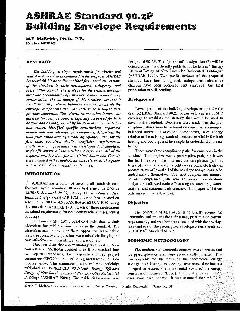
ASHRAE Standard 90.ZP Building Envelope Requirements M.F. McBride, Ph.D., PoE. Member ASHRAE
ABSTRACT
The building envelope requirements for single- and multi-family residences contained in the proposed ASHRAE Standard 9O.2P were distinguished from previous versions of the standard in their development, stringency, and presentation format. The strategy for the criteria development was a combination of consumer economics and energy conservation. The advantage of this strategy was that it simultaneously produced balanced criteria among all the envelope components and was 25% more stringent than previous standards. The criteria presentation format was different for many reasons. It explicitly accounted for both heating and cooling, varied by location of the air distribution system, identified specific constructions, separated above-grade and below-grade components, determined the total fenestration area by a trade-off equation, and, for the first time, contained shading coifficien! requirements. Furthemwre, a procedure was developed that simplifies trade-offs among all the envelope components. All of the required weather data for the Ullited States and Canada were included in the standard/or easy reference. This paper reviews each of these significant features.
INTRODUCTION
ASHRAE has a policy of revising all standards on a five-year cycle. Standard 90 was first issued in 1975 as ASH RAE Standard 90-75, Energy Conservation in New Building Design (ASHRAE 1975). H was then updated on schedule in 1980 as ANSIIASHRAE/IES 90A-1980, using the same title (ASHRAE 1980). Each of these publications contained requirements for both commercial and residential buildings.
On January 29, 1984, ASHRAE published a draft addendum for public review to revise the standard. The addendum encountered significant opposition in the public review process. Many questions were raised challenging the cost-effectiveness, consistency, application, etc.
H became clear that 0 new strategy was needed. As a consequence, ASHRAE decided to split the standard into two separate standards, fonn separate standard project committees (SPC 90.1 and SPC 90.2), and start the revision process anew. The commercial standard was officially published as ASHRAEIIES 90.1-1989, Energy Efficient Design of New Buildings Except New Low-Rise Residential Buildings (ASHRAE 19890). The residential standard was
designated 90.2P. The "proposed" designation (P) will be deleted when it is officially published. The title is "Energy Efficient Design of New Low-Rise Residential Buildings" (ASHRAE 1990). Two public reviews of the proposed standard have been completed, independent substantive clianges have been proposed and approved, but final publication is still pending.
Background
Development of the building envelope criteria for the draft ASHRAE Standard 90.2P began with a series of SPC meetings to establish the strategy that would be used to develop the standard. Decisions were made that the prescriptive criteria were to be based on consumer economics, balanced across all envelope components, save energy relative to the existing standard, account explicitly for both heating and cooling, and be simple to understand and easy to use.
There were three compliance paths for envelopes in the standard. The simplest was a prescriptive path, but it was the least flexible. The intermediate compliance path in teons of complexity and flexibility was a complete trade-off procedure that allowed all of the envelope components to be traded among themselves. The most complex and comprehensive compliance path was an annual hour-by-hour analysis that allowed trade-offs among the envelope, waterheating, and equipment efficiencies. This paper will focus only on the prescriptive path.
Objective
The objective of this paper is to briefly review the economics and present the stringency, presentation format, requirements, and weather data associated with the development and use of the prescriptive envelope criteria contained in ASHRAE Standard 90.2P.
ECONOMIC METHODOLOGY
The fundamental economic concept was to ensure that the P!escriptive criteria were economically justified. This was implemented by requiring lhe incremental energy savings, both heating and cooling, over some time horizon to equal or exceed the incremental costs of the energy con~ervation measure "(ECM), both materials and labor, over ,Some time horizon. It was assumed that the ECM
Merle F. McBride is a research associate with Owens~Corning Fiberg-las Corporation, Granville, OH.
would be totally financed as part of the home mertgage. The t",conomic methodology can be stated as
Incremental Energy Cost Savings Over Time;" (I) Incremental Costs of ECM Over Time
In equation form, it is
where
FYSh --
Ph Sh FYSc
Pc Sc !J.FC
S2
FYSh . Ph 'Sh + FYS,
'Pc'S,;" !J.FC·Sz (2)
incremental first-year energy savings for heating, Btn/ttl; price of fuel for heating, $/Btu; ec.onomic scalar for heating, dimensionless; incremental first-year energy savings for cooling, Btn/ftz; price of fuel for cooling, $IkWh; economic scalar for cooling, dimensionless; incremental first cost of ECM, $/ftz; economic scalar for ECM, dimensionless.
Economic scalars, Sh and SCI are simply the "modified" uniform present-worth factors corresponding to the time horizon (life), with discount rate and fuel escalation rates assumed. ("Modified" means that the dollar value of energy savings may not be constant from year to year but increases over time at some projected rate of change.) Representative values range from 7 to 22. The economic scalar, Sz, is the present-worth factor that accounts for the financing costs (mortgage, points, and down payment) and tax savings associated with the cost of the ECM. Maintenance and replacement costs were assumed to be zero for all envelope ECM over the economic life used in the analysis. Representative values of S2 range from 0.6 to 1.2. The distinct advantage of the economic scalar methodology is the ability to represent various cost-effectiveness criteria in_ a consistent set of equations.
On a unit area basis, the first-year heating savings is
where
!J.U
HLF HDD65 AFUE
HDE
FYSh
= Ll.U·HLF·HDD65 AFUE'HDE
(3)
incremental change in V-value for materials, Btn/ft2. OF; heating load factor, h/day; heating degree-days base 65°F, °F·day; annual fuel utilization efficiency, dimensionless; heating distribution efficiency, dimensionless.
This equation can be modified to apply to otber types of heating systems by substituting the appropriate overall coefficient of performance for the AFUE variable. For example, a beat pump could be analyzed by substituting the
heating season performance factor (HSPF) for the AFUE. One would also have to incorporate the appropriate conversion factors at the same time.
On a unit area basis. the first-year cooling savings is
!J.U·CLF 'CDH74 FYSc = (4)
SEER'CDE
where
cooling load factor, dimensionless; CLF CDH74 = SEER CDE
cooling degree-hours base 74°F, °F·h; seasonal energy efficiency ratio, BtuhlW; cooling distribution efficiency, dimensionless.
Combining Equations 2, 3, and 4 produces
!J. U' HLF . HDD65 • Ph 'Sh
AFUE·HDE !J.U·CLF·CDH74·P 'S
+ SEER .CDE c c;" !J.FC 'S2'
(5)
Equation 5 represents the complete equation used to set the criteria. It is simply an equation for a straight line when the inequality sign is replaced with an equal sign. Conversion factors have been intentionally omitted from all equations. Additional details on the economic development are available (McBride and Powell 1990; McBride 199Ib).
Intercept Equations
Starting with a specified increase in the EeN, for example, a change in insulation levels, the first costs were fixed and the unknowns became tbe climates, both HDD65 and CDH74, tbat were necessary to satisfy Equation 5. These heating and cooling values were easily determined by solving for each variable independently. The calculated values of HDD65 and CDH74 were called intercepts and appeared on the criteria curves (CDH74 vs. HDD65) as the points where the criteria line intersects the horiwntal and vertical axes. The heating intercept equation is
where
HDD65 = !J.FC· AFUE . HDE Sh
!J. U ·HLF 'Ph'S2
(6)
Sh/S2 economic scalar ratio (SRh) for heating, dimensionless,
and the cooling intercept equation is
where
CDH74 = !J.FC·SEER 'CDE Sc
!J.U·CLF·P ._ c S2
(7)
S/S2 economic scalar ratio (SRc) for cooling, dimensionless.
Implementation
In order to calculate the intercepts, specific values had to be substituted into Equations 6 and 7. Cost data at the consumer level were assembled for construction materials and fuels across the country. National averages were used for the standard development. Construction costs were assembled as an ASHRAE research project and then reviewed, changed, and augmented by the SPC. The fuel costs used were determined by weighting the fuel costs for 73 locations by the number of single-family housing starts. The weighted national values were $0.527/thenn for natural gas and $0.0786lkWh for electricity.
A central forced-air gas furnace (AFUE = 0.68) and air conditioner (SEER = 8.5) were assumed as the representative equipment. Heating distribution efficiencies (HDE) were set at 75 % and the cooling distribution efficiencies (CDE) at 80%.
The heating and cooling scalar ratios were both set equal to 18. This value was selected to achieve a 25 % energy reduction from the current standard using a national energy model (McBride and Powell 1990). Furthermore, a scalar ratio of 18 was defendable when assuming representative economic input parameters (McBride 1991b).
The heating and cooling load factors were derived from detailed hourly computer simulations. Load factors were developed for both heating and cooling seasons and for all components above and below grade (McBride et a1. 1991; Christian and Strzepek 1987).
Using all of these parameters, an optimization technique was developed and used to select the specific constructions as the criteria. Details on the optimization technique have been documented (McBride 1991a).
The final results are presented in Table 5-3 for singlefamily houses and in Table 5-6 for multi-family structures. Breakpoints are presented in Table 5-6 which account for the thermal impact of higher internal loads to exterior envelope areas for multi-family structures (McBride et a1. 1991).
Balance
"Balance" was the term applied to the envelope requirements to mean that each component had to satisfy the same economic hurdle. The economic hurdle was that each component would meet the same scalar ratio as used in Equation 5, which represented a totally different concept than in previous versions of the standard.
Balance was an issue at two levels. One level existed between Jrutior envelope components, such as ceilings, walls, floors, and fenestration. Economic balance avoided the potential problem of requiring too stringent a level for one component while making another component's requirement too lenient.
The second level existed between options within a major component, such as frame and masonry walls. Previous versions of the standard had a single wall require-
727
ment and required equal energy performance for trade-off calculations. The economic balance concept advocated separate wall requirements, one for frame walls and another for masonry walls, because the materials and applications were different, which means their costs were different. Therefore, each wall would have to meet the same scalar ratio requirement, but the frame wall would use less energy.
STRINGENCY
The stringency issue was defined by requmng the prescriptive criteria in the new standard to be 25 % more energy efficient than the existing standard. The 25 % requirement was a value set by the 90.2 committee. The intent was to save a significant amount of energy. A value less than 25 % was not considered worth the effort to develop a new standard, and values greater than 25 % were considered too bold for a single revision.
There was a distinct relationship between the desired 25 % energy savings and the scalar ratio. As expected, a low scalar ratio would not save any energy relative to the existing standard. Conversely, selecting a scalar ratio too high would not survive the consensus review process. Determining the relationship and selecting a scalar ratio of 18 was accomplished by developing a national energy model (McBride and Powell 1990). Once the scalar ratio was determined, it was used to determine the energy-saving opportunities of foundations (Christian 1988).
PRESENTATION FORMAT
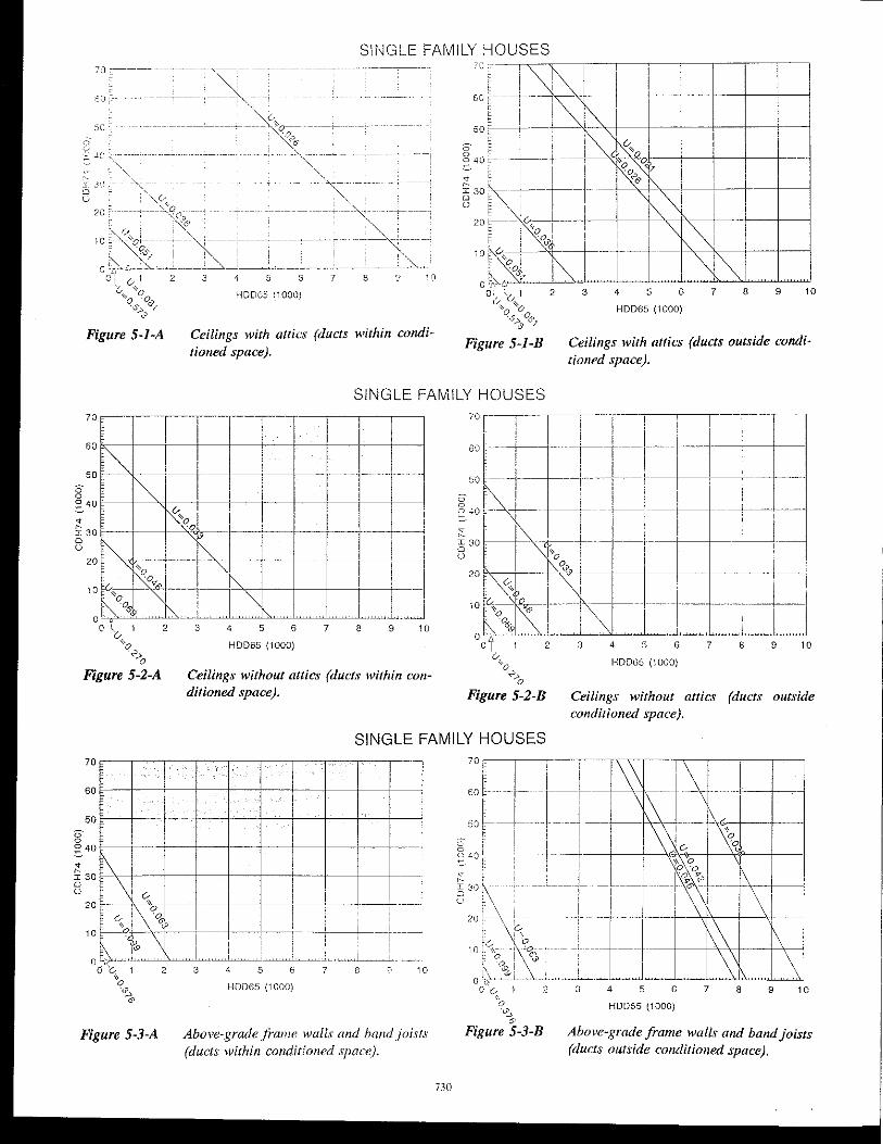
The presentation format for the prescriptive envelope criteria was graphical. A typical example is Figure 5-1-AlB. The criteria figure numbers correspond directly with the draft standard. (All figures begin with the number five because they are contained in section five of the draft standard.)
The horizontal axis is heating degree-days base 650F (HDD65) and the vertical axis is cooling degree-hours base 74 OF (CDH74). This format explicitly accounts for both the heating and cooling dependence. The negative slope of the criteria lines is a direct indication of the coolirtg impact. Accounting for the cooling dependence represents a significant improvement over previous versions of the standard.
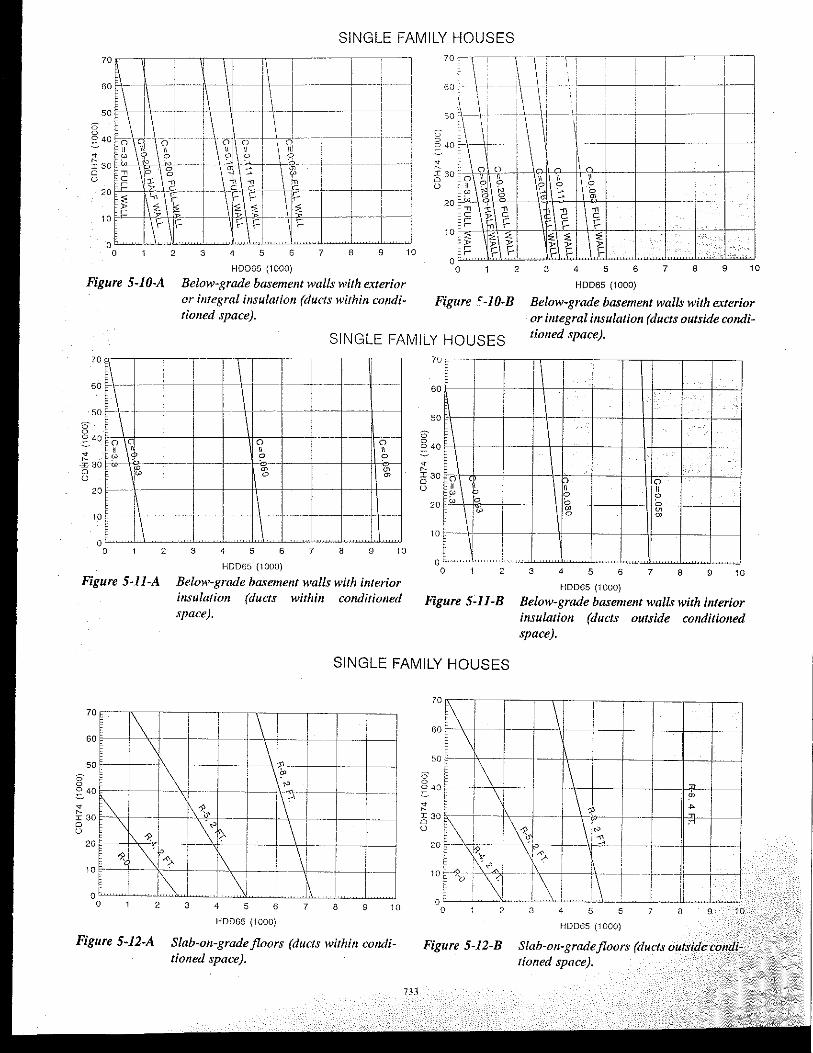
The diagonal lines identify the prescriptive requirements as distinct bands. The requirement is unifonn within a specific band and only changes in adjacent bands. The criteria are expressed in various terms depending upon the component. Thermal transmittance (U) values were used for above-grade components, including the inside and outside air film coefficients at winter design conditions. Thermal conductance (C) values were used for below-grade components to avoid the problem of accounting for the surrounding soil. Thermal resistance (R) values were used for slab insulations.
This format had several advantages. It was easy to use, simple to understand, avoided any proprietary products as criteria, and allowed alternative materials and manufacturers to be specified in demonstrating compliance.
In each figure the first or least stringent requirement was the uninsulated base-case construction. The base case for fenestration was single glazing with an aluminum frame. Each successive band represented an increase in the stringency of the criteria until HDD65 reached a value of 10,000. Above 10,000 HDD65, the criteria were presented in tables because there was no significant cooling dependence.
Determination 01 Compliance
To use the figure, one simply locates the city or location of interest by the intersection of the HDD65 and CDH74 values as a single point. The point falls either within a band or on a diagonal line that defines the requirements. When the point is located clearly between the requirement lines, compliance is easily determined. However, when the point lies close to or on a require~ent line, it may be difficult to graphically determine the correct requirement. Compliance can be determined by calculating the relative climate ratio (RCR) as presented in Equation 8. This applies to all requirement lines, including fenestration shading coefficients.
where
IHDD65
ICDH74
HDD65c CDH74c RCR = Ti'fi"",,",'" +
IHDD65 ICDH74 (8)
heating degree-days base 65°F for the city or location being evaluated, cooling degree-hours base 74°F for the city or location being evaluated,
= beating intercept of a specific requirement line from tbe appropriate table (5-3 or 5-6), cooling intercept of a specific requirement line from the appropriate table (5-3 or 5-6).
Then determine which requirement the city or location shall meet using the following:
Single-Family Housing
(a) If RCR > 1.0, then the city or location is above the line.
. (h) If RCR < 1.0, then the city or location is below the line.
(c) If RCR = 1.0, then the city or location is on the line and must meet the more stringent requirement.
728
Multi-Family Structures
(a) If RCR > 1.0, then the city or location is above the line.
(h) If RCR < 1.0 and CDH74c > BPCDH74, then the city or location is above the line.
(c) If RCR < 1.0 and CDH74c < BPCDH74, then the city or location is below the line.
(d) If RCR = 1.0, then the city or location is on the line and must meet the more stringent requirement.
where
BPCDH74 breakpoint cooling degree-hours base 74°F.
PRESCRIPTIVE ENVELOPE REQUIREMENTS
Initially, prescriptive envelope requirements were developed for every type of component the SPC could envision. This led to 128 figures, which were deemed too many. To simplify the standard, many components were consolidated.
Examples of the consolidation include above-grade frame walls and band joists; above-grade concrete, masonry, or log walls with exterior or integral insulation; abovegrade concrete, masonry, or log walls with interior insulation; concrete or masonry walls adjacent to unconditioned space; all basement walls (shallow, deep, and all-weather wood); below-grade basement walls with interior insulation; crawl space walls (concrete, masonry, and frame); and all fenestration (windows, sliding glass doors, and skylights). The consolidation was justified in many cases because the differences in the criteria were small. In other cases, the consolidation was either a judgment or political decision based on the affected industries.
The prescriptive envelope requirements also varied depending upon the type of residence: single-family houses, manufactured housing, and multi-family structures. Each will be reviewed in detail.
Mandatory Requirements
There are mandatory calculation requirements regarding thermal bridges and anomalies that all buildings must follow in demonstrating compliance. Parallel and series paths must be analyzed for wood-framing members and webs in masonry construction. Fenestration must account for the thermal performance of the center-of-glass, edge-of-glass, and frame (ASHRAE 1989). Metal framing members can be analyzed by either using the zone method (ASHRAE 1989) or Equations 9 through 11 and the parallel path correction factor from Table 5-1.
1 Uj = R'
1
(9)
(10)
where
R,
total thermal transmittance of the envelope assembly, Btulh·ft2. of; total resistance of the envelope assembly, h·ft2.oF/Btu; thermal resistance of the series elements (for i =
1 to n), excluding the parallel path element(s), h·ft2.oF/Btu; equivalent resistance of the element containing the parallel path, h·ft2.oF/Btu.
The value of Re is defmed by Equation 11:
Re = (R-value of insulation) 'Fe (11)
where
Fe correction factor from Table 5-1, dimensionless.
Laboratory- or field-measured data can be substituted for the required calculations provided they are obtained from one of the following test methods:
(a) guarded hot plate (b) heat flow meter (c) guarded hot box (d) calibrated hot box
(ASTM CI77-85) (ASTM C518-85) (ASTM C236-87)
(ASTM C976-90)
Single-Family Houses
All of the envelope criteria are presented in Figures 5-1-AlB through 5-16-AlB for locations below 10,000 HDD65. For locations above 10,000 HDD65, the criteria are presented in Table 5-2. The intercepts used to prepare the figures are presented in Table 5-3.
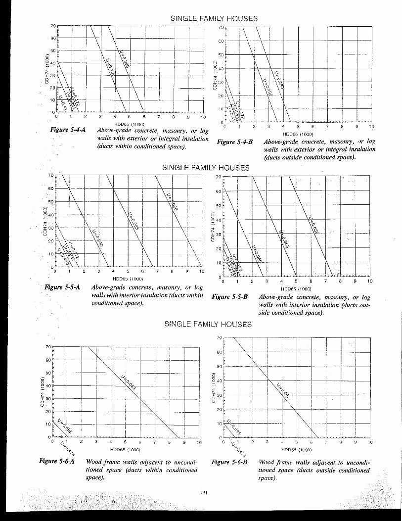
There were several unique features of the criteria. Different criteria were developed for ceilings with attics and ceilings without attics (flat or cathedral) and accounted for the location dependence of the air distribution system. Concrete or masonry walls had different criteria depending upon the location of the inSUlation (exterior or integral and interior, both above grade and below grade). Criteria were developed for surfaces adjacent to unconditioned spaces (frame or masonry walls and frame floors). Separate criteria for doors were developed depending upon the
materials (architectural wood or thermally insulating materials). Fenestration shading criteria were developed for the first time in the standard.
The top half (A) of each figure represents the air distribution system located within the cundidoned space, while the bottom half (B) of each figure represents the air distribution system located outside the conditioned space. Houses with the air distribution system located within the conditioned space had less stringent criteria than those where the air distribution system was outside the conditioned space. The use of dual figures served two purposes. First, separate figures clearly delineated the impact of the location of the air distribution system. Second, they served as a simple trade-off system because no calculations were required.
In addition to the prescriptive thermal requirements, a limit was imposed on the amount of fenestration area that was allowed in the prescriptive compliance path. The initial value was set at 15 % of the conditioned floor area, and no more than 8 % could exist on any single orientation. The final criterion eliminated a prescriptive requirement and requires the trade-off procedure to be used to determine the allowed fenestration area. The basis for the trade-off analysis is that the fenestration is 18% of the conditioned floor area and uniformly distributed on the four cardinal orientations. Furthermore, no area limitations were imposed by orientation.
Manufactured Housing
Initially, criteria figures for manufactured housing were developed in the same fomlat as for single-family houses. During the first public review, comments were received that did not support that format. Instead, the traditional format of a Ua -value for the entire envelope was preferred. The Vo would be defined for zones that follow state boundaries, similar to the procedure used by the Department of Housing and Urban Development in the federal standard (P.L. 93-383). The SPC worked with the manufactured housing industry and converted to the U 0 format. The stringency developed in the initial format was retained. The fmal zones are presented in Figure 5-17. Hawaii and U.S. possessions are included in Zone I while Alaska is Zone III. The criteria are presented in Table 5-4.
TABLE 5-1 Wall Sections with Metal Studs-Parallel Correction Factors
~
Size of Gauge of Spacing of Cavity correction I studs studs Studs, in. Insulation Factor
R-Value (Fc)
2 x 4 1B - 16 16 a.c. R-.ll 0.50
2 x 4 1B - 16 24 c.c. R-ll 0.60
2 x 6 18 - 16 16 o.c. R-19 0.40
2 x 6 18 - 16 24 c.c. R-19 0.45
729
Slr~GLE FAMILY HOUSES
o . ,~, 0 ::: ..:;; ~ - ---- - - - --- - ----------
Figure 5-1-A
H0065 (1000)
Ceilings with attics (ducts within cOIuii(ioned space).
Figure 5-1-B
6 7 8 9 10
HDD65 (1000)
Ceilings with attics (ducts outside conditiolled space).
SINGLE FAMILY HOUSES -- ~-r--'~-'----,
HDD65 (1000)
Ceilings without attics (ducts within conditioned space).
HDD6S (1000)
Ceilings without attics conditioned .\pace).
10
(ducts outside
SINGLE FAMILY HOUSES
60~-~~-~~-+--+~'-~-~-~-~-~
50~-t--,---+--+---t--~-~-~--+-~
Figure 5-3-A
... + __ L __ I I , !
-t--+----t----j ..... J~.~.:. ... !
7 8 10
HOD65 (1000)
Above-gratle frame walls and band joists (ducts within conditioned space).
730
70 E I ' . 1 I i
60t+
T-f--
50 ~---~ [--i--+---f'\ '! I
~. 40 t- --l----l--l-----"-, ~,-+----';'<"----l----I
2 3 4 5 6 7 8 9 10
HDD55 (1000)
Above-grade frame walls aad baad joists (ducts outside conditioned space).
SINGLE FAMILY HOUSES
::r-t --+--[-'\ -1- -+--I~]-- I l)- III\J '"J ---l ~~ II j ! .•. i /" i + I \!-_.~ __ -+-I::f-----c'f-'--=f--_
c. ~ ~ tt' 'I L: 20! '-c--, !Dk! I 10 0,:- <;;,)' - I II 1o~.~.t;4-:--li ..... 1 .. -----+--1-o "~~~ ~Lc~, ,~I . ~"P.~ ~
o 2 3 4 5 6 7 8 9 10 0 ~ __ }~\:~ _, __ , "~_~I \ I . '-' ""'"u, "CM.~,"""~~~ Figure 5-4-A
60
50
" o . o 40E--:::. t:
2
Figure 5-5-A
HOD6S (1000) 0 1 2 3 4 5 6 7 8 9 10
Above-grade concrete, masonry, or log HOD6S (1000)
walls with exterior or integral insulation Figure 54-B Above-grade concrete, masonry, or log (ducts within conditioned space). walls with exterior or integral insulation
(ducts outside conditioned space).
SINGLE FAMILY HOUSES
i --I
I . ,
j , --,-
- -~--~---I
-I--I---t-
3 4 5 6 7 8 9 10
HDD65 (1000)
Above-grade concrete, masonry, or log walls with interior insulation (duels within conditioned space).
70
60
50
0 0 040
q ~
I30 0 ()
20
10
Figure 5-5-8
SINGLE FAMILY HOUSES
HOD6S (1000)
Above-grade concrete, masonry, or log walls with interior insulation (ducts outside conditioned space).
1- ----i (/ , __ '1°0.
I
(/
~ ~'" I 2
Figure 5 -6-A
I I , !
""~. 3 4 5 6 7 8 9 10
HDD65 (1000)
Wood frame walls adjacellf to ullconditioned space (ducts within conditioned space).
73J
Figure 5-6-8 Wood frame walls adjacent to u/lcoadilianed space (ducts outside conditioned space).
SINGLE FAMILY HOUSES
Figure 5-7-A HDD65 {1000)
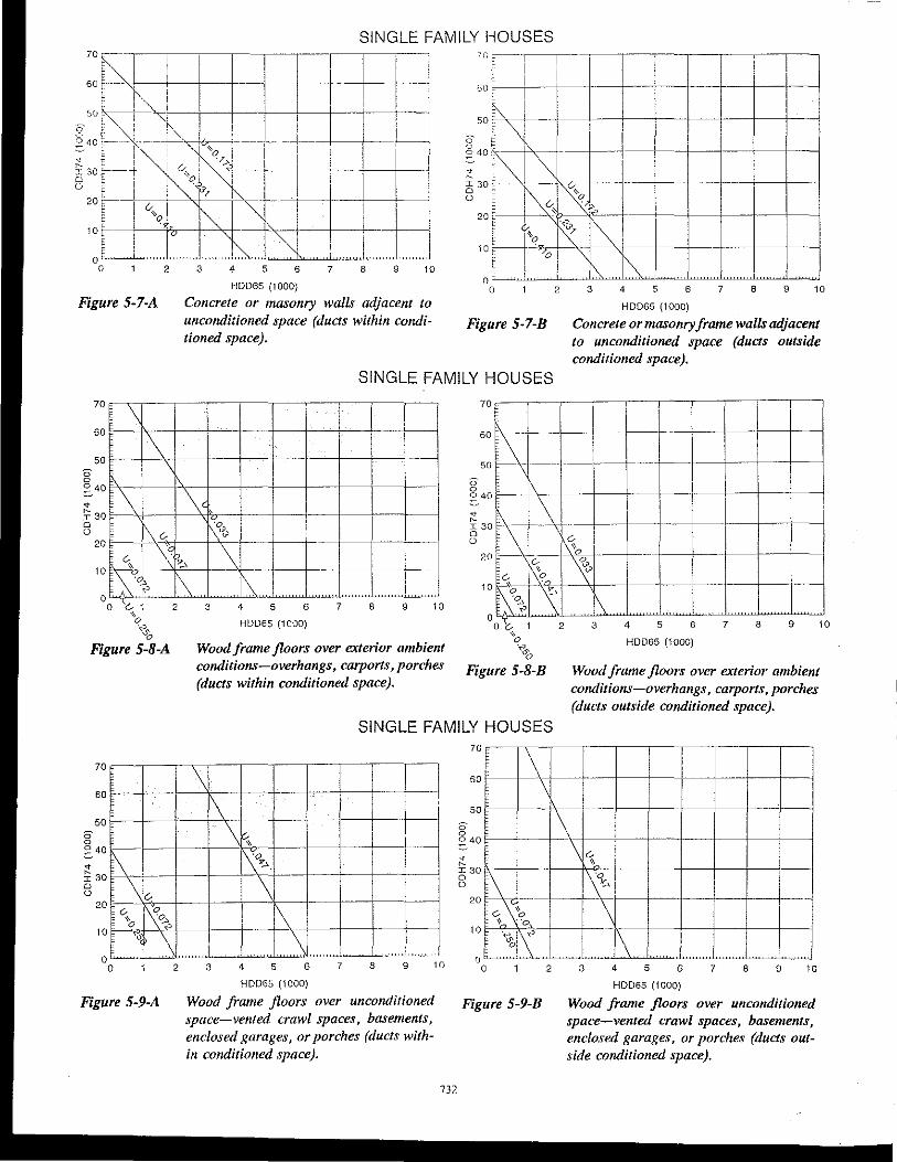
Concrete or masonry walls adjacent to uncorulitioned space (ducts within corulitioned space).
>30
50
• ~ I30 o o
20
10
o
--~
i ~
~ I c I ,
1 c C \J !.
=1···· ~ ~.d=~-~ 1 t ~ i ,~ '- (/1.
f I ~,i--"'~ ,-----r- 't" I~ :: v B E I'\J I
~-TV70! " "~ , I I 1\ ~ ,,' !, ~
o 2 3 4 5 6 7
HOD6S (1000)
.~
, 8 9 10
Figure 5-7-8 Concrete or masonry frame walls adjacent to uncorulitioned space (ducts outside corulitioned space).
SINGLE FAMILY HOUSES
70
'\ \
60
50
" o ~ 40
~
j: 30 o
\ \" o
20
10
0
1\ '" ~\:9~
rS:~ ,c~~ [\
o \::, 1 2 '0
'''' "'0 Figure 5-8-A
1\"'0l \ !-
1\ i I 3 4 5 6 7 8 9 10
HDD65 (1 cao)
Wood frame floors over exterior ambient conditions-overhangs, carports, porches (ducts within corulitioned space).
HDD65 (1000)
Wood frame floors over exterior ambient cotulitions-overhangs, carports, parches (ducts outside cOllditioned space).
SINGLE FAMILY HOUSES
70
60
50
" o
~\ ~ 40
~
j: 30 o o \",
20
'" , 10 W~
o o
"0
~ ~ Figure 5-9-A
\ 1\ !
i~ \ ~ r-"~
I~--1---"" r--
~
\ T i
1\+- r r--" r--
\1 I " L,~~
2 3 4 5 6 7 8 9 10
HDD65 (1000)
Wood frame floors over uncorulirioned space-vented crawl spaces, basements, enclosed garages, or porches (ducts within corulitiolled space).
732
70
60
50
" o ~ 40
• ~ I30 o o
20
10
"
~ f \1 I \ , 1'\
-_.- ~-~ "-, E r-- \ ! '" , 0
~~ " I~ i, ~ I t~ f%ts:" " , 1\ o 2 3 4 5 6 7 8 9 10
Figure 5-9-B HDD65 (1000)
Wood frame floors over unconditioned space-vented crawl spaces, basements, enclosed garages, or porches (ducts outside corulitioned space).
° 2
Figure 5-10-A
Figure 5-11-A
60 f---f-'\-I
0-o
2
SINGLE FAMILY HOUSES
I
-1
3 4 5 6 7 8 9
HOD65 (1000)
Below-grade basement walls with exterior or integral insulation (ducts Wilhill cOllditiolled space).
10
70 c r--:-TT-\ I I :~
60 \-~ ---\-\-i, .-+--+-t--L-~ I
SO ~_J --~ :_:-_- '{-__i,----+: - 1
\I 0
" m
~ C .-.-
'" F 2 3 4 5 6 7 8 9 10
HOD65 (1000)
Figure <-1O-B
SINGLE FAMILY HOUSES
Below-grade basement walls with exterior or illlegral insulation (ducts outside conditioned space).
HOD6S (1000)
Below-grade basement walls with interior insulation (ducts within conditioned space).
70
60
50
0-o ~ 40
;': I30 o u
20
10
o
, I t
-
1
~\ ~\ ~ go, 10
-~ \ I~ ,-I r 1 I F-"..C
o 2
Figure 5-11-B
, I ,
---
-
q <;) \I , " " ~ rn
0 m
3 4 5 6 7 8 9 10
HOD6S (1000)
Below-grade basement walls with interior insulation (ducls outside conditioned space).
SINGLE FAMILY HOUSES
-tl I ! ! •
----:---
3 4 5 6 7 8 9 10
HOD6S (1000)
, 1-+' --1 +- - --t----il--t--------I
~,lc tlf: f_I~' . ~)~--! r-' r-+--l I~ 8 ~ I i ~ i 1~1; I I' Ij II
20 ~--- --i-- .- ___ I -- "t---,-~-- r-'d--l---f- _~_I __ .
t ~?! : ~ I !! I I 10~~O~~ - I ~jtt---tJ~LJ o o 2 3 4 5 5 7 a 9 10
HDD65 (lOOO)
Figure 5-12-A Slab-all-grade floors (ducts within cmU/itlolled space).
Figure 5-12-B Slab-on-gradefloors (ducts outside conditioned space).
SINGLE FAMILY HOUSES
70 T I I 1 I 70 C\~I ---r-II ----'-----'-------'1 ------,---,~---,
60 ~ 1\ I ~1 t I ~ -l 60 t_:t,'-- I --r--l-+--+---f-~ 50[-L\+-l- i i---t ; I i 50~-'
~4r}~ __ 1 __ 1 -: __ J J5-_L _ ~ ___ ~J_-----1 __ ' g ~ ---+-\-.-~.-t-! _+ __ 1_--+-_--+-_--j ~ ~\ I 1\ n: i j"§,-__ -i _________ L_~: ____ ._. ~---_____i ~ 40 ~-- , ! 01 I, 8::i-~~~J'~~-'---i\T-~r--!-- :-1 8:: t --~[l=-~~! 1+-
10 C~\"'I--tl -1----1---+t--:-----:----;---1 t~, D% 1 " oLL \ ,..Lj,_.~_L' .L~ 10r~r,'-1 . f----+--j---I---+--a 1 2 3 4 5 6 7 8 9 10 0 L,~LL.LLL~L;b..L~LL~..ul~~~~
HDD65 (1000) 0 2 3 4 5 6 7 8 9 10
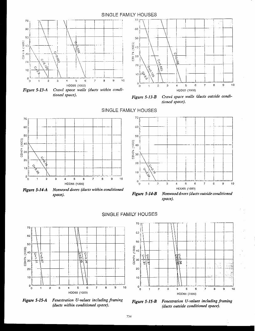
Figure 5-13-A Crawl space walls (ducts within cOlldi- HOD65 (1000)
tioned space), Figure 5-13-B Crawl space waLL, (ducts outside cOfrdi-tioned space),
SINGLE FAMILY HOUSES
70 r-!
-~t-f---
1
60
50
70 r--§ ~-'----i -'-1----'----'1--'--' -'--'----'---'11 60 [ ---+-11
1
- '--1 I
g ~ 40
~ ~
I30 o
1\ I -,- ++ ---i-+- I
l I
50 ~- ! ---+,--+-+-+-+---J l I' g :: i _____ _
~ 40
~30:-~,-I+ c---- --f----+----j \ "-
o
'\ "-0-0
20
-19 1\ 0 o 2
Figure 5-I4-A
70
60
50
g ~ 40
~ ~
I30 o o
20
10 0
,
o
\
e c 11 ~ ~ ~
Figure 5-15-A
.
2
"----,-
1 -
+-3 4 5 6 7 8 9 10
HDD65 (1000)
Nonwood doors (ducts within conditioned space).
ollll' LLJ 2°1-~ ~r-I-i--t-I 1 11,---1----1 10 [--''oN''"' I ! - I-+-I··----I---I' -1--
o§ f \1 . II I L1~ ~,~~ o 2 3 4 5 6 7 8 9 10
HDD65 (1000)
Figure 5-14-B Nonwooddoors (ducts outside conditioned space).
SINGLE FAMILY HOUSES
\ ----
I
, e e I
~l~ {>e --w, '
i I.
3 4 5 6 7 8 9
HDD65 (1000)
Fenestration U-values including framing (ducts within conditioned space).
1
10
734
70 II ! I \! I I cT- --I--I-I--+-t--f------ ---50f--- -- --r--W--- ---1---1---1---1
a E i ~ 4o!---- -----+-+-+-+--1---1 :! ~ c: c Ir, e" I 30 l.l1-b'Ol' ---+--- f--------\( '?'--I--+--+--+--+-~ 8 I~ . ~ ;' 20~++--~--+_~4_-+--4_--t-~---f-~
Figure 5-15-B
HDD65 (1000)
Fenestration U-values including framing (ducts outside conditioned space).
SINGLE FAMILY HOUSES
I ! i
!
I , i I , , 2 3 , 5 6 7
HOD6S (1000) HOD6S (1000)
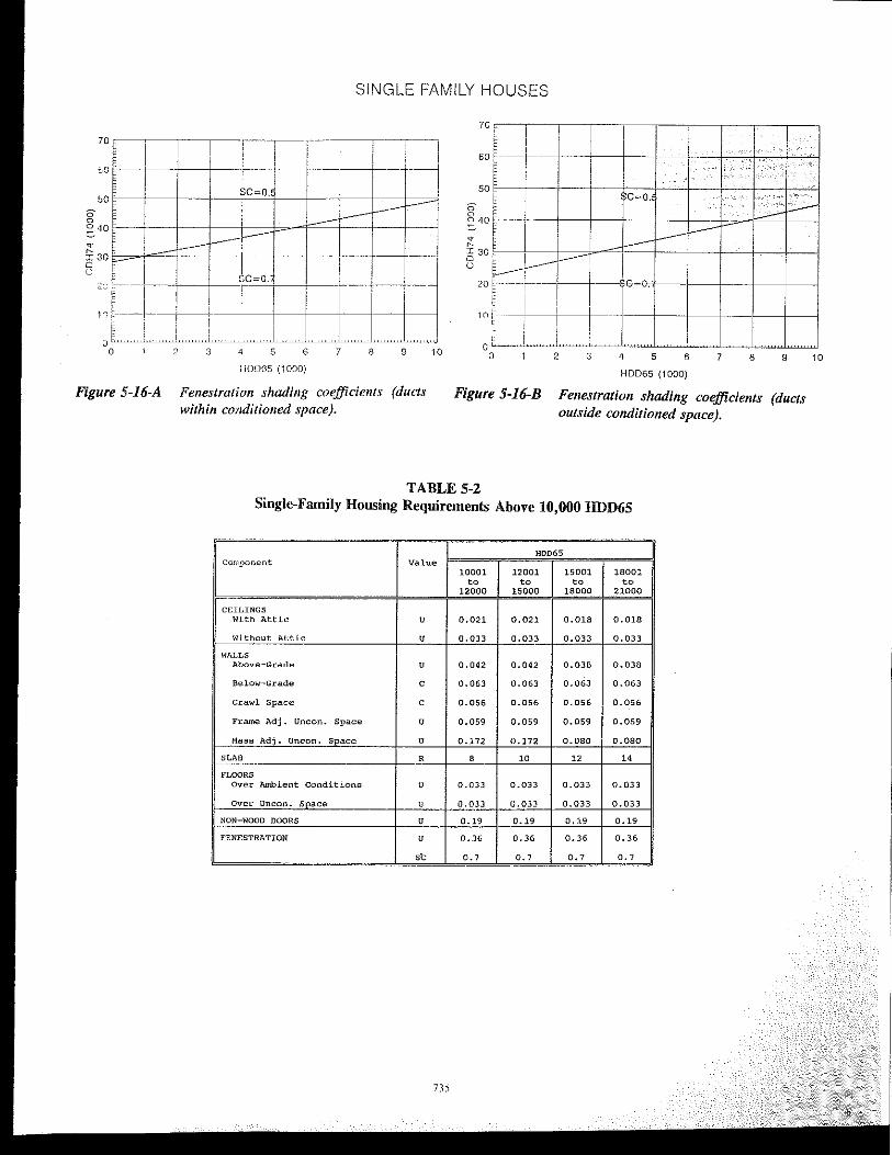
Figure 5-16-A Fenestration shading coefficients (ducts within cOllditioned ~pace).
Figure 5-16-B Fenestration shading coefficients (ducts outside conditioned space).
TABLE 5-2 Single-Family Housing Requirements Above 10,000 HDD65
HDDGS Component Value
10001 12001 15001 18001 to to to to
12000 15000 18000 21000
CEILINGS With Attic U 0.021 0.021 0.018 0.018
without Attic U 0.033 0.033 0.033 0.033
WALLS Above-Grade U 0,042 0.042 0.038 0.038
Below-Grade C 0.063 0.063 0.063 0.063
Crawl SpacE! C 0.056 0.056 0.056 0.056
Frame Adj. Unecn. Space U 0.059 0.059 0.059 0.059
Mass Adj. Unecn. Space U 0.172 0.172 0.080 0.080
SLAB R 8 10 12 14
FLOORS Over Ambient Conditions U 0.033 0.033 0.033 0.033
Over Unean. Space u 0.033 0.033 0.033 0.033
NON WOOD DOORS U 0.19 0.19 0, :;9 0.19
FENESTRATION U 0.36 0.36 0.36 0.36
," 0.7 0.7 0.7 0.7
735
,ole. 5-}
FIG. 0->
FIG. ,-,
FIG. ,-, INTG. INS.
FIG. H INS.
FIG. 5-6
FIG. 5-7
FIG. H
FIG. ,-,
FIG. 5-10
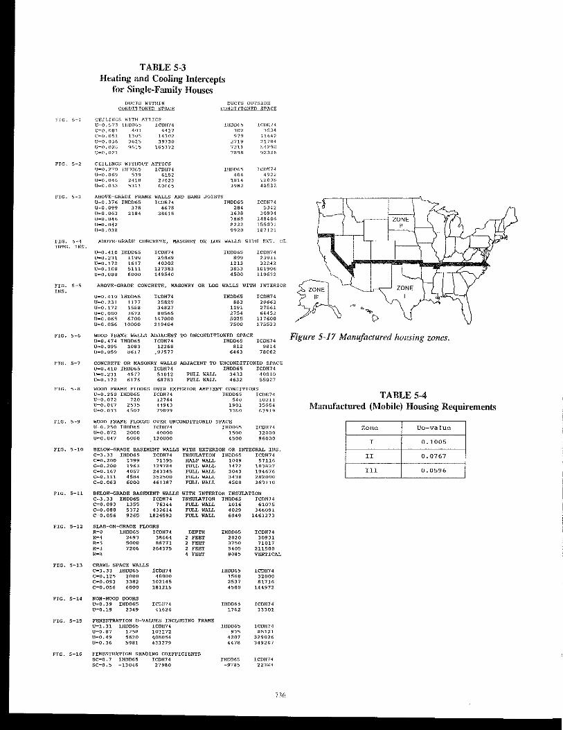
TABLE 5-3 Heating and Cooling Intercepts
for Single-Family Houses DUCl'S WITHIN DUCTS ou'rSlDE
CONQJ .. TTONED SPACJ; £,ONDI1'IONED SPA~E
,:Ell,HIC" I'ilTH A'l"1lCS u=o 573 IHD;)6~ ICDH74 LHDD65 ICD!174 u=o. on '" 4417 '" 3534 U~[). [)Sl 130<; 14302 no 11447 U=O.OJ6 3625 39730 2719 31784 U=O.026 9615 105172 7211 84298 V=0.071 7898 92326
CEILINGS WITHOUT ATTICS U=0.270 IHDD65 ICDH74 IHODGS ICDH74 U=O.06~ m 6152 '" 4972 U=0.046 2418 27623 1.814 22098 U=0.033 5311 60665 3983 4()53?
ABOVE-GAADE FRAME WALLS AND """ JOISTS U=0.376 IHDDGS ICDH74 IHODGS ICDH74 U=0.099 m 6678 '" 5342 U=O.06] 2184 386;(1 1638 30894 U=0.046 7868 148406 U"'0.042 8222 :155091 U=0.038 9920 187121
ABOVE-GRADE CONCRETE, MASONRY OR LOG WALLS WITH EXT.
U=O.410 IHOD65 ICOH74 IH0065 ICDH74 U=0.231 1199 29889 '" 23911 U=O.I72 1617 40302 1213 32242 U=0.100 5111 127383 3833 10190(, U=0.080 6000 149540 4500 119632
OR
ABOVE-GRADE CONCRETE, MASONRY OR LOG WALLS WITH INTERIOR
U,O;0.410 tH0065 U=0.231 1177 U=O.l72 1588 U=0.080 3672 U=0.065 6700 U=0.056 10000
WOOD FRAME WALLS U=0.474 IH0065 U=0.095 1083 U=0.059 8617
tCDH74 25829 34827 80565
147000 219404
ADJACENT ICOH74
12268 .97577
IHD065
'" 1191 2754 5025 7500
TO UNCONDITIONED SPACE IHDD65
on 6463
ICOH74 20663 27861 64452
117600 175523
1CDH74 9814
78062
CONCRETE OR MASONRY WALLS ADJACENT TO UNCONDITIONED SPACE U=0.410 tHDD65 ICDH74 IH006S ICOH74 U=0.231 4577 51012 FULL WALL 3433 40810 U=0.172 6176 68783 FULL WALL 4632 55027
WOOD FRAME FLOORS OVER EXT8RIOR AMBIENT CONDITIONS U=0.250 IH0065 ICOHH TH0065 ICDH7~ U=O.072 no 12764 '" 10211 U=0.047 2535 44943 1901 3590,4 U=0.033 4507 79899 3380 63919
WOOD FRAM' FLOORS OVER UNCONDITIONED SPACE U-0.250 IH0065 ICDH74 IH0065 ICOHH U=O.072 2000 40000 1500 32000 U=0.047 6000 120000 4500 96000
BELOW-GRADE BASEMENT WALLS WITH EXTERIOR OR INTEGRAL INS. C=3.33 IHOD65 tCDH74 INSULATION IHOD65 ICDH7~
C=0.200 1399 71395 HALF WALL 1049 57116 C=0.200 1963 129784 FULL WALL 1472 103827 C=0.167 4057 243345 FULL WALL 3043 194676 C=0.111 4584 352500 FULL WALL 3438 282000 C=0.063 6000 461387 FULL WALL 4500 369110
FIG. 5-11 BELOW-GRADE BASEMENT WALLS WITH INTERIOR INSULATION C=3.33 1H0065 ICOH74 INSULATION IHDD65 ICOH74 C=0.093 1355 76344 FULL WALL 1016 61075 C=0.080 5372 432614 FULL WALL 4029 346091 C"'0.056 9265 1826592 FULL WALL 6949 1461273
FIG. 5-12 SLAB-ON-GRADE FLOORS
FIG. 5-13
FIG. 5-14
FIG. 5-15
R=O IHOD65 ICOH74 R=4 2693 38664 R=5 5000 88771 R=3 7206 264375 R=8
CRAWL SPACE WALLS C=3.33 IHDD65 C""0.125 2000 C",0.093 3382 C=0.056 6000
NON-WOOD DOORS U=0.39 IHOD65 U=0.19 2349
ICDH74 40000
102145 181215
ICDl!74 ~ 1626
DEPTH 2 FEET , FEET 2 FEE'I' 4 FEET
FENESTRATION U-VALUES INCLUDING FRAME U=1. 31 IHOD6S ICOH74 U=0.87 1258 103172 U=0.49 5620 4;08054 U=0.36 5981 433279
FIG. 5-16 FENESTRATION SHADING COEFFICIENTS SC=O. 7 IHOD65 ICDH74 SC=0.5 -13046 27980
IH0065 2020 3""/50 5405 8085
TH0065 1500 2537 4500
IH006S 1762
IH0065
'" 4207 4478
tHOD65 -9785
ICDH74 30931 71017
211500 VERTICAL
ICDH74 32000 81"116
144972
ICDH74 33301
ICDH74 85121
329026 349207
ICDH74 22384
,G ."" ()
Figure 5-17 Manufactured hOl!si1lg 201les,
TABLE 5-4 Manufactured (Mobile) Housing Requirements
Zone Ua-value
I 0.1005
II 0.0767
III 0.0596
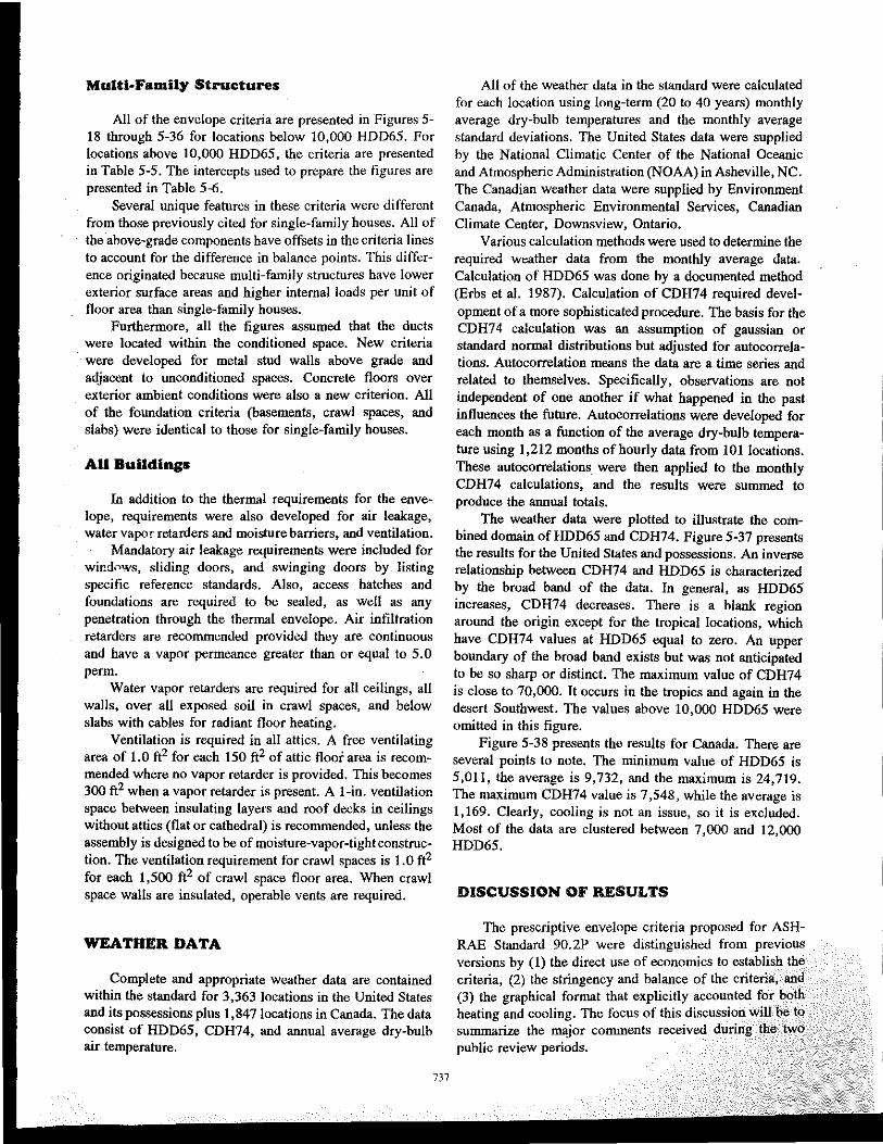
Multi.Family Structures
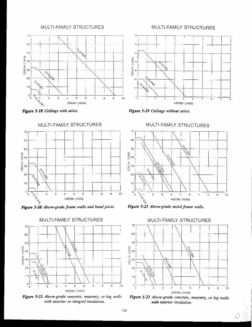
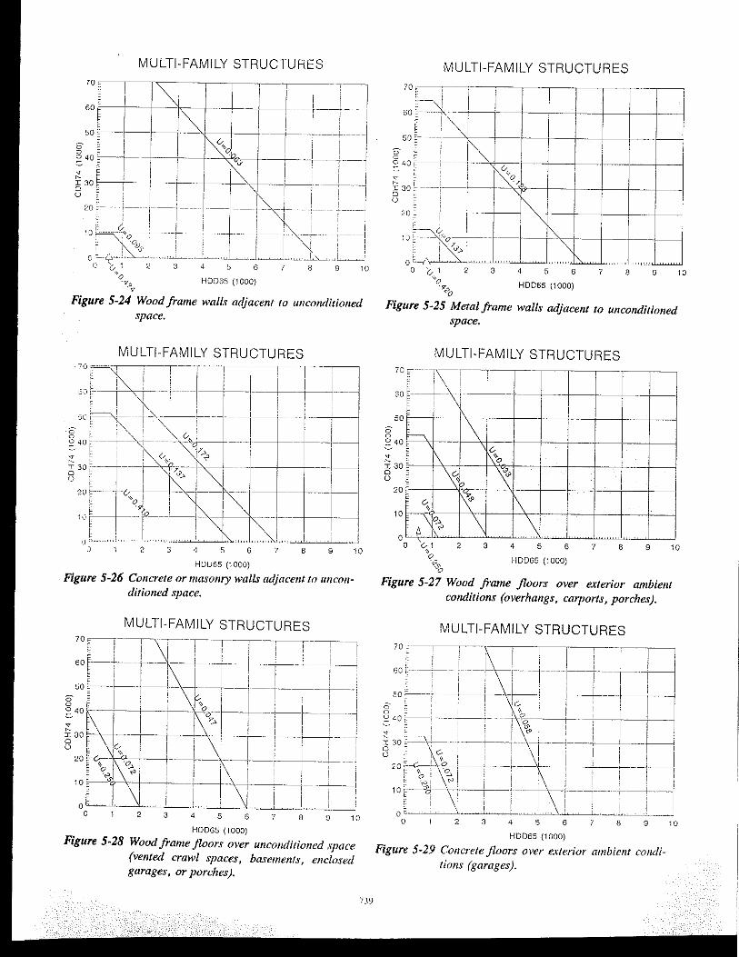
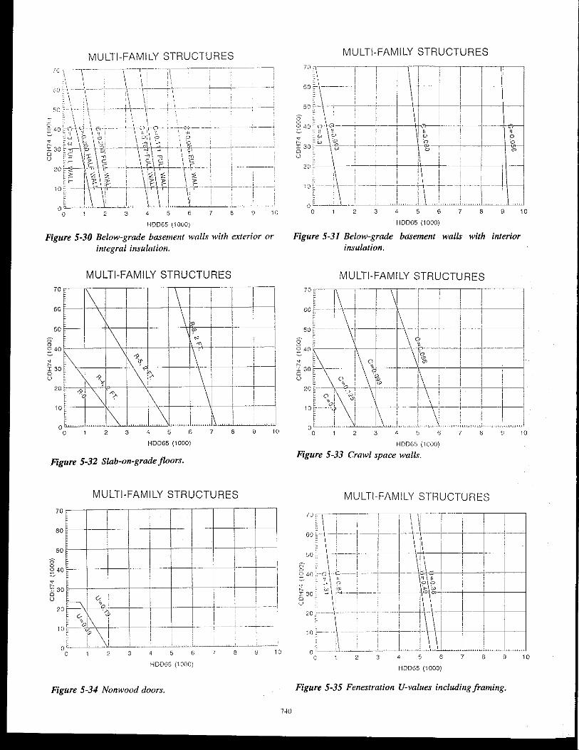
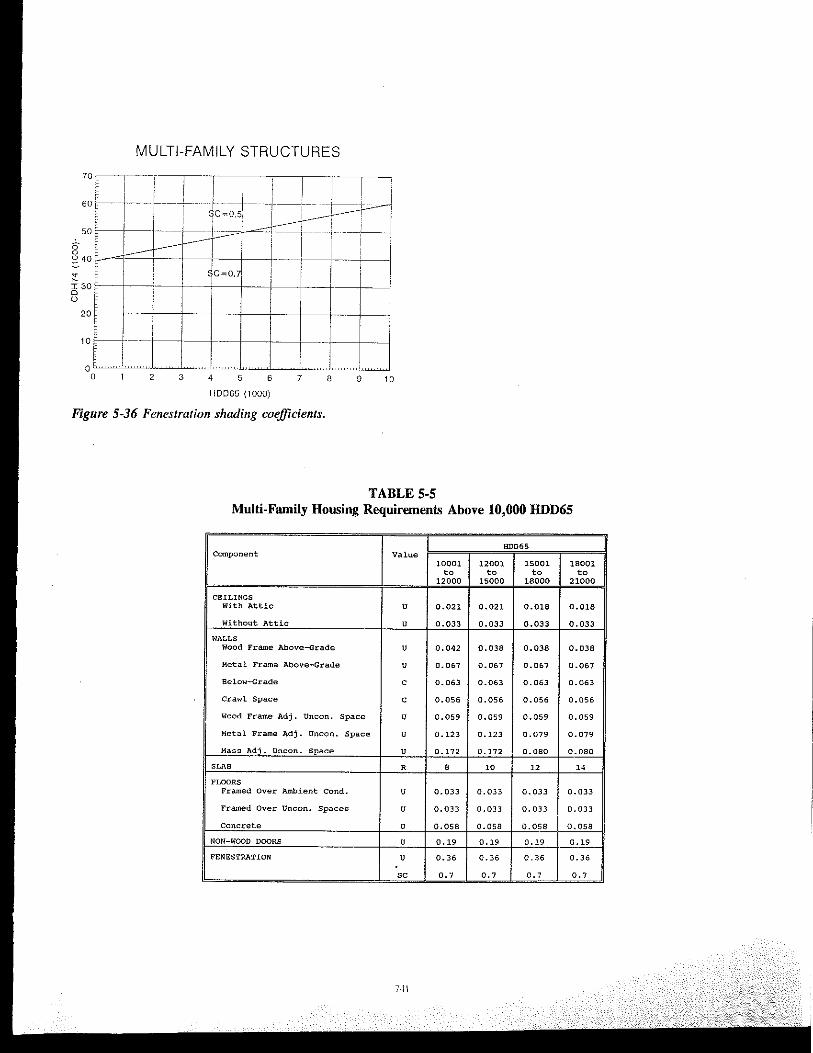
All of the envelope criteria are presented in Figures 5-18 through 5-36 for locations below 10,000 HDD65. For locations above 10,000 HDD65, the criteria are presented in Table 5-5. The intercepts used to prepare the figures are presented in Table 5-6.
Several unique features in these criteria were different from those previously cited for single-family houses. All of the ahove-grade components have offsets in the criteria lines to account for the difference in balance points. This difference originated because multi-family structures have lower exterior surface areas and higher internal loads per unit of floor area than single-family houses.
Furthermore, all the figures assumed that the ducts were located within the conditioned space. New criteria
. were developed for metal stud walls ahove grade and adjacent to unconditioned spaces. Concrete floors over exterior ambient conditions were also a new criterion. All of the foundation criteria (basements, crawl spaces, and slabs) were identical to those for single-family houses.
AU Buildings
In addition to the thermal requirements for the envelope, requirements were also developed for air leakage, water vapor retarders and moisture barriers. and ventilation.
Mandatory air leakage requirements were included for wind0'Vs, sliding doors, and swinging doors by listing specific reference standards. Also, access hatches and foundations are required to be sealed, as well as any penetration through the thermal envelope. Air infiltration retarders are recommended provided they are continuous and have a vapor permeance greater than or equal to 5.0 perm.
Water vapor retarders are required for all ceilings, aU walls, over all exposed soil in crawl spaces, and below slabs with cables for radiant floor heating.
Ventilation is required in all attics. A free ventilating area of 1.0 ft2 for each 150 ft2 of attic floor area is recommended where no vapor retarder is provided. This becomes 300 ft2 when a vapor retarder is present. A I-in. ventilation space between insulating layers and roof decks in ceilings without attics (flat or cathedral) is recommended, unless the assembly is designed to be of moisture-vapor-tightconstruction. The ventilation requirement for crawl spaces is 1.0 ft2 for each 1,500 ft2 of crawl space floor area. When crawl space walls are insulated, operable vents are required.
WEATHER DATA
Complete and appropriate weather data are contained within the standard for 3,363 locations in the United States and its possessions plus 1,847 locations in Canada. The data consist of HDD65, CDH74, and annual average dry-bulb air temperature.
737
All of the weather data in the standard were calculated for each location using long-term (20 to 40 years) monthly average dry-bulb temperatures and the monthly average standard deviations. The United States data were supplied by the National Climatic Center of the National Oceanic and Atmospheric Administration (NOAA) in Asheville, NC. The Canadian weather data were supplied by Environment Canada, Atmospheric Environmental Services, Canadian Climate Center, Downsview, Ontario.
Various calculation methods were used to determine the required weather data from the monthly average data. Calculation of HDD65 was done by a documented method (Erbs et al. 1987). Calculation of CDH74 required development of a more sophisticated procedure. The basis for the CDH74 calculation was an assumption of gaussian or standard normal distributions but adjusted for autocorrelations. Autocorrelation means the data are a time series and related to themselves. Specifically, observations are not independent of one another if what happened in the past influences the future. Autocorrelations were developed for each month as a function of the average dry-bulb temperatUre using 1,212 months of hourly data from 101 locations. These autocorrelations were then applied to the monthly CDH74 calculations, and the results were summed to produce the annual totals.
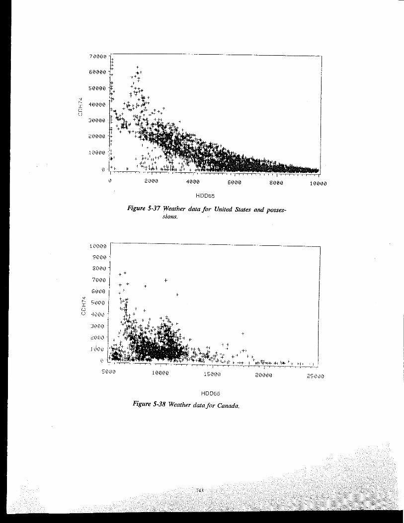
The weather data were plotted to illustrate the combined domain ofHDD65 and CDH74. Figure 5-37 presents the results for the United States and possessions. An inverse relationship between CDH74 and HDD65 is characterized by the broad band of the data. In general, as HDD65 increases, CDH74 decreases. There is a blank region around the origin except for the tropical locations, which have CDH74 values at HDD65 equal to zero. An upper boundary of the broad band exists but was not anticipated to be so sharp or distinct. The maximum value of CDH74 is close to 70,000. It occurs in the tropics and again in the desert Southwest. The values above 10,000 HDD65 were omitted in this figure.
Figure 5-38 presents the results for Canada. There are several points to note. The minimum value of HDD65 is 5,011, the average is 9,732, and the maximum is 24,719. The maximum CDH74 value is 7,548, while the average is 1,169. Clearly, cooling is not an issue, so it is excluded. Most of the data are clustered between 7,000 and 12,000 HDD65.
DISCUSSION OF RESULTS
The prescriptive envelope criteria proposed for ASHRAE Standard 90.2P were distinguished from previous versions by (1) the direct use of economics to establish the criteria, (2) the stringency and balance of the criteria, and (3) the graphical format that explicitly accounted for both heating and cooling. The focus of this discussion will be to summarize the major comments received during the two public review periods.
MULTI-FAMILY STRUCTURES
MULTI-FAMILY STRUCTURES
20 ~"o \~ '0 \
10 iP&
h. \ 0~~~~~~~~~~~~~~~~~~~~~'0 o 61 2 3 4 5 6 7 8 9
" q,;........ HDD65 (1000)
~
Figure 5-20 Above-grade frame walls and band joists.
MULTI-FAMILY STRUCTURES
i -I +--+~+--4---,\(~---i~+-+,---t-1
l-~~----! . I
-j----l---,-,
2 3 4 5 6 7 6 9 10
HDD65 (1000)
Figure 5-22 Above-grade concrete, masonry, or log walls with exterior or integral insulation.
738
MULTI-FAMILY STRUCTURES
HOD65 (1000)
Figure 5-19 Ceilings without attics.
MULTI-FAMILY STRUCTURES
-+---+-t-P
50 ~----,
6
MULTI-FAMILY STRUCTURES
7 6
HOD6S (1000)
9 10
9 10
Figure 5-23 Above-grade concrete, masonry, or log walls with interior insulation.
MULTI-FAMILY STRUCTURES
'0 c ________ <!~ -- --~ __
~Ol ~ ,,'°09 ; !;S. C ~--L;.:,-,--!,-- "i __
I.} (" 1 2
'0 ''';>7
3 4 5 6 7 8
HOD6S (1000)
Figure 5-24 Wood frame walls (l[fjacent to unconditioned space.
MULTI-FAMILY STRUCTURES
,O~~ l-r- 1
r
[ll-1-r--1l
1
eel[-- ' 'tt-I-·-----I-I-I,--r-~ !;, Ii,
, " , I '
I 30 c---+----i-- f-;---I--, --- . -----
8 20~.-.--I-ud-,>~-~ i t f-',:H-J--tl-' ---l"-"LJJ
J 1 2 3 4 5 6 7 S 9 10
HD065 (1000)
Figure 5-26 Concrete or masonry walls adjacent to unconditioned space.
MULTI-FAMILY STRUCTURES 70 ~~----------r-~ ---, -·---,--------"------r--------,------,---r--~'---------;
f: i ' ' I ' i I ! I I ~ I I r i 1 ! ! ; i !
60 ~---+-·----t,-'---!--'----+-- ----,---,+ -'-;~----'i---- :-------1
- 50 r+-I-+--t~j--i~+-+--~-I ~ 40 ~-'~-i ----+--,--)-----' \~o;+-- i -----1 ~-~---i-l ~ 30 c--+-+--~I- --! --+--+--'-~----i 8 ~ i~\ I ! i I Iii ! I
20 !:--6;:--, '0 ' -------1----;---; ---T--r-~~: -,- --~' - -, ---: L3J.~ 0;,: I· '--+. I Ii, I , " +- I i ,; i ' I
) - I Tl ,--I - 11--- l --I o 2 3 4 5 6 7 8 9 10
HOD6S (1000)
Figure 5-28 Wood frame floors over unconditioned space (vented crawl spaces. basements. enclosed garages, or porches).
739
MULTI-FAMILY STRUCTURES
70C--,----,---,---,---,---~--,---,_--,_--,
~ ill j I
::r~~ll i_T .~ § )~---I~~-~t-I -t-I---t-----t- 1
~ 30 ; ····-,~-H~--""o -i+-lt-' --+---+--+-+----1
u 2: 0o~ [+-~,,-+,~ --+---l-Jj J-<~~l" .... =r .. '1 c .~ o (.,1 2 3 4 5 6 7
'0 '9'';:>0 HDD65 (1000)
8 9
Figure 5-25 Metal frame walls ~acent to unconditioned space.
MULTI-FAMILY STRUCTURES 70 - --! __ : I
++-F I .
i t I iii I f'-___ -+-____ 1--1---, ' " !
. , ,
~l-r f-\.~
60
50
c. l"c I,\q , "\ ~ I ~
& c. ~ ri p--, \ \ . 6 "
20
10
o
10
o C. 1 2
" 3 4 5 6 7 8 9 10
o ." "'0 HD065 (1000)
Figure 5-27 Wood frame floors over exterior ambient conditions (overhangs, carports, porches).
MULTI-FAMILY STRUCTURES
:: i-' ... uu~ i T -1---+- I-I I ~ 50c~,-L-+--t-!~---i----~~i- ·-1
g ~ i: i 'b i I I i I I 2 40,-.. --, . --.-.- -, -·OT---r----' r I -1
~ 30 ,- \ GL-~--i.~~ i-JI---+-~i ~H, il 0;:: \%' I ~ I : i ,
20 ~~t-- \S--t-~r---"~i---; _ ... ---:----T--]---'Il
j-~ \i~: ---:.~-t \i--~-=~~ .1---1 o 1 2 0 4 5 6 8 9 10
H0065 (1000)
Figure 5-29 Concrete floors over exterior ambient conditions (garages).
MULTI-FAMILY STRUCTURES
I,: ;~-\--\\- __ ~\-TI,_,,=~I\, _' -===~ _____ -, ,-w ~ ---- \-- :\ \'
:;0 ~ - \ ----~-\-----: -- ---t-t--- \i---- ----J--~ ___ ; -- --------.. -----'< , , ; \ \
S 40 ~I-\('--' \ (':t ~--I,--O-.'-O--,- 0- --::., L h \ \ \1 : \\ '\ ~\
~ -~ \~" \~ i \~I:: ~ ~30~S\%: ~- -T--\-~~-+ 4 ~~-~--
V '0 ~- \~~-\-f;--l--'-\~l~ ~: -\~~ ---~- ' ,-""" I r: ~ I~ r:- I ~
10 t --l \-'Ir-: --\ -~\" -1--' ! :
~ I I ~ i: Otl......~ _---.L ___ l~ _ ~..l~'-c'_~ o 1 2 3 4 5 6 8 9 10
HDD65 (1000)
Figure 5-30 Below-grade basement walls with exterior or integral insulation.
6
HOD6S (1000)
Figure 5-32 Slab-an-grade floors.
7 8
MULTI-FAMILY STRUCTURES
70
60
50 8 ~ 40
" ~ I30 o o
! I IT
1 !
i -
I I I 1 , , ! I ,
I
-
E I ~ J-, \'0 I -----t- ----, ~::b i , ~ , , , :: ~'ol- L ~-- L- 1 t ----. -oi __ ,"_L_:~, _,~:_, __ I _~I, ,, ____ 1 ____ 1 ~" __ ;...._' __ _
o 1 2 3 5 6 8 9 10
HOD6S (1000)
Figure 5-34 Nonwood doors.
740
MULTI-FAMILY STRUCTURES
",q-'---TE' '-1- I I I ' , [:1 , i ! : ! I I I 60,-I---L,' -I i i- -1'-i-------!----1--e--'\' , " ,!
5C[\-' '~+-I tl ! I g :: .; I I I i
~ 40 >,':- 'i " ' I ,'i!~-', ---'1--- 1 'iH 'T :w? I Ii' ~:: I ?
§ 30-'"-\~---i--:---~---j, ~ i ::~ ~ I
20 'c- --r -"-;~ tti-,: --f-----t --1 : I ,1 I I I
':~JtT-l-~--H-t-- '-:---:-o 1 2 3 4 5 6 7 8 9 10
HDD6S (1000)
Figure 5-31 Below-grade basement walls with interior insulation.
MULTI-FAMILY STRUCTURES
70:-1--1 --T -r-' 1--[ 1
60'e. ---I - --1- ---+-T14 ' . i
o 50~--~--1 i-- I ---11
ui-i--i---1 ~ 40 ,-I ~- - 'ri --r---j---r-1--1 ~ 30 [- "-~,jl- - -i- --~------ '----,-____t_ I u ~ (1 i ~ iii
20 [------"'c-i- -1""--;- L ' , , j r '/ ' ,I I I ~ (1 i ~' , I t \0>' U] I: i I f--10[-'<i---r--' - -1- -~--'----~ ~. ,I ~
o ~.-.. L. 'C_~;~, ~' ~, cl~ ~~. ,~'" ,-,- " __ "" o 2 3 4 5 6 7 8 9 10
HDD65 (1000)
Figure 5-33 Crawl space walls.
MULTI-FAMILY STRUCTURES
70 :,- \----; ,I \--'1[---:--- i ~ i I __ II \ I i
60[ i-------l ---r~-'\ ! ! 1 Ii !
50 -- \ :---1-'--1 t - :---i -1--I --r-~40~\ ~ --- +- ~~\i'I--: --l-
;;: ,-:-'-\? I '; e I I ' I
::c: 30 ~--~-Y'~ -------1-- \0 01 -1 ----+--+--+--j g \ i \ II iii I j
20. - ---\.- - ---!----t- --t---+i----j--f.-----j
':_\ __ ~_, __ -1--:\ l,~L~"~i ~~"" 012345678
HOD65 (1000)
9 10
Figure 5-35 Fenestration U-values including framing.
MULTI-FAMILY STRUCTURES
70 ;: T I-r 60 E---- f----1- -J" -+- --I---~- ---~: --+ !
501 I j--biC"O~:-l---: ___ j
10 r-r----i-----i---l- --i---c---+--- ~ t .. o ~~~~"~~~.. . i . o 2 3 4 5 6 7 8 9 10
HDD65 (lOOO)
Figure 5-36 Fenestration shading coefficients.
TABLE 5-5 Multi-Family Housing Requirements Above 10,000 HDD65
HDD65 Component Value
10001 12001 15001 18001 to to to to
12000 15000 18000 21000
CEILINGS with .... ttic u 0.021 0.021 0.018 0.018
Without Attic U 0.033 0.033 0.033 0.033
WALLS Wood Frame Above-Grade U 0.042 0.038 0.038 0.038
Metal Frame Above-Grade U 0.067 0.067 0.067 0.067
Below-Grade C 0.063 0.063 0.063 0.063
Crawl Space C 0.056 0.056 0.056 0.056
Wood Frame Adj. Uncon. Space U 0.059 0.059 0.059 0.059
Metal Frame Adj. Uncon. Space U 0.123 0.123 0.079 0.079
Mass Adj. Uncon. Space U 0.172 0.172 0.080 0.080
SLAB R 8 10 12 14
}o'LOORS
Framed Over Ambient Cond. U 0.033 0.033 0.033 0.033
Framed Over Uncon. Spaces U 0.033 0.033 0.033 0.033
concrete U 0.058 0.058 0.058 0.058
NON WOOD DOORS U 0.19 0.19 0.19 0.19
FENESTRATION U 0.36 0.36 0,36 0.36
sc 0.7 0.7 0.7 0.7
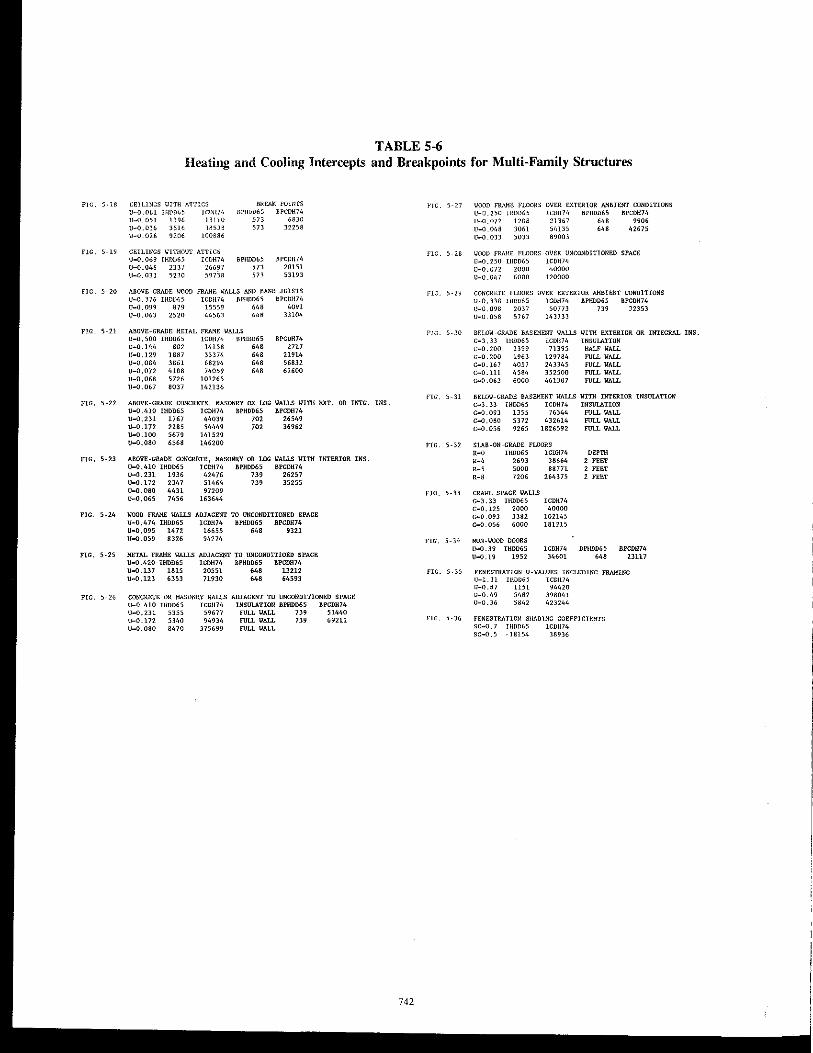
TABLE 5-6 Heating and Cooling Intercepts and Breakpoints for Multi-Family Structures
r'IG. 5·]8 CE1UNGS \.lITH ATTICS BREAK FOHns
U-0.061 IHl'D65 it'U1I)4 U_0.051 1196 13Li.U U-O.036 3516 U-0.026 9206
lR5J~
100886
llPlIDD65 BPGDH74
on 683C on 32258
FlG. 5-19 CEILINGS I<ITHOUT ATTICS U-0.069 [HOOGS ICOH74 BPIID065 I.IPCOIl74 U-O.046 2331 26697 on 20151 U-O.033 52JO 59738 573 53193
FIG. 5-20 ABOVE-GRADE \/000 FRJ>.JiE \,tALLS AND BAND JOISTS
FIG. 5-21
U-o.376 1110065 lCOH74 /lPHOD65 BPCDH74 U_0.099 879 15559 648 4091 U-0.063 2520 4456.1 648 33104
AIIOVE-GRADE METAL FRA'1E WALLS U_0.500 IHDD65 ICOH74 BPH0065 U-0.144 '" 14158 '" U-0.129 1887 33374 '" U-o.OM 3861 68291, '" U-O,072 41118 710059 '" U_0.068 5726 101265 U-O.067 8037 142136
IIPCOH74 2717
21914 56832 62600
FIG. 5_22 AIIOVE-GRADE CONCRETE, MASONRY OR LOG VALLS VITH EXT. OR INIG. INS. U-0.410 lHDD65 IGDH74 BPHDD65 BPCDH74 U-0.231 1767 44039 702 26549 U_O.I72 2185 54449 702 36962 U-0.I00 5679 141529 U-0.080 6568 146200
FIG. 5-23 ABOVE-GRADE CONCRETE, MASONRY OR LOG WALLS YITH INTERIOR INS. U-0.41O IHDD55 ICDll74 BPHDD55 BPCDH74 U-O.231 1936 42476 739 26257 U-O.I72 2347 51464 739 35255 U_0.080 4431 97209 0_0,065 7456 163644
FIG. 5-24 WOOD FRAME IlALLS ADJACENT TO UNCONDIT10NED SPACE U-0.474 IHDD65 ICDH]4 BPHOD65 BPCDH74 U-0.095 1472 16655 648 9321 U-{l.059 8325 94274
FIG. 5-25 METAL FRAME IlALLS ADJACENT TO UNCONDITIOED SPAGE U-0.420 IHDD65 ICDII74 BPIIDD6S BPCDH74 u-o.137 1815 20551 648 13212 U_O .123 6353 71930 648 64593
FIG. 5-26 CONCRETE OR MASONRY WALLS ADJACENT TO UNCONDITlON8D SPACE U-0.410 IH0D65 ICDH710 lNSUlJ\.TlON BPHD06S BPCDH?4 U-{l.231 5355 59677 FULL WALL 739 51440 U-O.I72 5340 94934 FlILL VALL 739 69211 U-O.080 8470 375699 FULL VALL
742
j'IG. 5-27
flG. 5-28
flC. ,·29
11000 FRAME FLOORS OVER D.:TERTOR MillEN'!' CONDITIONS U-O.2S0 IHOD6~ lCOH74 BPHDD65 BPCD!!74 U_O.072 120B 2]367 61<8 9906 U_O,048 3061 51,135 , .. 42675 U_O.033 5033 89003
ImOll FRAME FLOORS OV£R UNCONOITIONED SPACE U_O.2~O lHDD65 lCOll74 U-O.072 2000 40000 U-O.OI,] 6000 120000
CONCIIETE FLOORS OVER EXTE'JUOR i'.ttBIENT CONDITIONS U-O,DB I11DD65 ICDH74 IIPflDD65 IIPCDfl74 U-0.098 203] 50773 739 32353 U_0.05S 5767 143733
BELOW-GRADE BASEMENT WALLS IH11I EXTIlRIOR OR INTEGRAL INS. C_3.D UlD065 ICOl!74 INSUlATION C_0.200 1399 71395 HALF WALL C-0.200 1963 129784 roLL WALL C--0.167 4057 243345 FULL VALL C_O.lll 4584 C-0.063 6000
352500 46138]
FULL VALL FULL VALL
FIG. 5-31 8ELOW-GRADE BASEMENT VALLS Vl111 INTIlRIOR INSUlATION C-3.33 IHOD6S ICOH74 INSULATION c-o.093 1355 76344 FULL WALL C-0.080 5372 432611, FlILL IIALL C_0.056 9265 1826592 FULL IIALL
FIG. 5·32 SlJ\.8-0N-GRADE FLOORS
'-0 IHD06S ICDH74 DEPTH ,-' 2693 38664
2 "" ,-; 5000 88771 2 FEET ,-, 1206 264375 2 FEET
FIG. 5-33 CRAWL SPACE IlALl.S C--3.33 IHDD65 ICDH74 C_0.125 2000 40000 C-0.093 3382 102145 C_0.056 6000 181215
FIG, 5-34 NON -woon DOORS U-0.39 IHD065 ICDH74 Bl'IlDD65 BPCDH74 \1-0.19 1952 34601 '" 23117
FIG. 5·35 FENESTBATION U-VALUES INCLUDING FRAMING U-1. 31 IUDD65 ICOU74 11-0.8) 1151 94420 [1-0.49 5462 398041 U-0.36 SlI4l 423244
FIG. 5·36 FENESTRATION SHADING COEFFICH-:NTS SC-0.7 TlUJD65 lCOll74 SC_O.S _1815!, 311936
7130ee
60000
sooeo 'T
" 4BOOB I 0 u
30000
20000
o
10000
9000
8000
7000
6000
" " I 0 u 4000
, +
2000 4000 6000 8000
HDD65
Figure 5-37 Weather data for United States aad possesSiOllS.
+ + + + 0' +
+
10000 15000
HDD65
Figure 5-38 Weather data for Callada.
743
20000
10000
25000
E .... nomi ...
The concept of using economics to set the criteria was universally supported. The controversy was in the application. Critical issues were the scalar ratio of 18, the basis for the material costs, and the use of national averages for the materials and fuels. Strong and valid comments were made that the scalar mtio should be lower (10) and that it should be higher (30). The primary driving force to lower it was affordability. Conversely, societal forces in terms of incremental power generation costs, pollution, retrofit costs, and long useful lives (50 years) all advocated a higher value. The final decision was to retain the scalar ratio at 18 since it was a delendable middle ground and it achieved the desired 25 % energy savings relative to the existing standard.
The basis for the material costs was challenged as not being representative. However, the SPC had initiated a formal research project that identified costs for ten regions around the country. Then the SPC augmented those costs with its own data. The fmal decision was to use national average values for the construction costs.
Arguments made on the construction costs were also made on the cost of fuels. Using national averages ignored the large variation that exists around the country. Determining a weighted average based on housing starts was an effort to account for the regional differences.
Achieving balance through economics was initiated to avoid problems, but some persisted. Above-grade frame and mass walls were an example. Two opposing forces govern the performance of walls. First, the load factors were different for cooling (frame walls = 1.0, mass walls with exterior or integral insulation = 0.82, and mass walls with interior insulation = 0.79). The lower cooling load factors for mass walls accounted for their thermal inertia. The heating load factors for all walls were identical (21.0). Second, the costs to insulate these walls were different, so their criteria were different. In frame walls it was easy to insulate the cavity, so it was cost-effective to have higher levels of thermal resistance than in mass walls. The net effect would be for mass walls to use more than three times the energy of frame walls in regions below 1,200 HDD65; between 40% and 80% more cooling energy in regions between 1,200 and 2,200 HDD65; and between 25% and 115% more energy in the 2,200 to 6,000 HDD65 region. Above 6,000 HDD65, all walls use the same cooling energy, but the actual values were diminished because cooling seasons were shorter.
Stringency
The stringency of a 25 % energy savings in the new standard was not a controversial issue. Once the prescriptive criteria were developed, it was clear that current construction materials and practices would achieve it.
744
Presentation Fonnat
The graphical format for the standard was well received. It met the goals of being easy to understand and simple to use. Explicitly accounting for the impact of cooling in the prescriptive criteria was recognized as a significant improvement. Specifying the criteria through the use of bands or regions recognized that only certain construction combinations can actually be built using currently available materials. Challenges were made to the use of dual requirements in single-family homes, depending upon the location of the air distribution system. This was intended to be a simple trade-off procedure but was interpreted as a ban on air distribution systems located outside the conditioned space.
Requirement.
The prescriptive requirement on fenestration area was a major controversial issue. The basis for the criteria cannot be analytically derived-it was a judgment decision. Strong opinions were held on opposite sides. A resolution was achieved, which is the ultimate goal of a consensus standard.
Prescriptive requirements for manufactured housing were developed even though the federal law is preemptive. The levels proposed were significantly lower than the 1974 HUD Title VI levels: Uo-0.157 in Zone I, Uo-0.126 in Zone II, and Uo-O.I04 in Zone III, which convert into a national average of Uo-0.145. The HUD zones matched the ASHRAE zones relative to the states included in each zone. However, the ASHRAE Uo-values (national average Uo-
0.092) were very similar to those proposed by HUD in their revision that is currently in progress: Uo-0.132 for Florida as Zone I, Uo-O.109 in Zone 2, Uo-0.096 in Zone 3, and Uo-0.079 in Zone 4, which led to a national average of Uo-
0.098 (Conner et aJ. 1992). The four new HUD zones represent different states than the 1974 zones, but the general trend is lower Vo -values in colder climates.
There were several differences in the multi-family structure prescriptive requirements relative to single-family houses. The most significant difference was the absence of dual curves depending upon the location of the air distribution system. It was the opinion of the SPC that multi-family structures tend to have air distribution systems located in the conditioned space because of adjacent and stacked dwelling units. Other differences were the inclusion of metal studs as wall construction options and concrete floors. These are typically required to meet fire codes. Breakpoints in the, above-grade components arose because of the differences in their thermal behavior. Finally, all of the below-grade criteria were identical to the single-family houses because neither data nor analytical capability were available to indicate they were difterent.
Weather Data
Weather data, for demonstrating compliance, were incorporated into the standard for the first time, receiving general acceptance. Inclusion of weather data for both the United States and Canada with a large number of locations eliminated any arguments that the data were too limited. Some felt the data may have been too abundant, but the SPC retained them all. Individual states that intend to adopt the standard could streamline the extensive data if necessary. However, the states would have had more difficulty in adding locations because CDH74 is not available or published elsewhere.
CONCLUSIONS
A strategy was developed and then utilized to generate the prescriptive envelope criteria for single- and multifamily residences in ASHRAE Standard 90.2P. The strategy was to economically justify the development of the criteria, achieve a 25 % energy savings relative to the current standard, explicitly account for both heating and cooling, and present the criteria in a graphical format. Many of these features were instituted for the first time in the standard. After the standard was developed, it was submitted for a public review. Revisions were made in response to the comments, so the second draft was then submitted to a public review. Comments on the second draft led to development of independent substantive changes that are currently being reviewed.
Economic Development
Economics was used to serve two purposes in the development of the prescriptive envelope criteria. First, it ensured the criteria were cost-effective. Second, it ensured that all of the envelope criteria were in balance. Both of these features were considered significant and beneficial.
Stringenc)'
The envelope criteria were developed to save 25 % more energy than those in the existing standard. This was a target set by the SPC. It was achieved through development of the national energy model.
Presentation Format
The presentation format incorporated two major cbanges from previous versions of the standard. First, it explicitly incorporated both heating and cooling dependence, which was considered a significant improvement. Second, the criteria were presented in terms of bands rather than as a continuum. The only similarity with previous versions of the standard was that it still had a graphical approach, which was easy to understand and simple to use.
745
Requirements
The requirements varied dependi'O" upon the type of residence. Single-family houses had dual criteria depending upon the location of the air distribul..iull system. The criteria were more stringent when the air distribution system was located outside of the conditioned space. Separate criteria were developed for above-grade walls and below-grade walls to avoid the problem of accounting for the surrounding soil. Shading coefficient requirements were developed for the first time in the standard.
The requirements for manufactured homes were presented in the traditional Uo-value concept with state borders acting as the division between the thermal zones.
The requirements for multi-family structures were separated from single-family structure requirements for all envelope components. Furthermore, the criteria lines contained breakpoints that accounted for the impact of smaller exposed envelope surface areas and higher internal loads.
Weather Data
Extensive tables of weather data were developed and included in the standard for the first time. A new weather variable, cooling degree-hours to base 74 OF, was developed for use in the standard. The tables contained 3,363 locations in the United States and possessions. Canada was included for the first time by incorporating 1,847 locations.
ACKNOWLEDGMENTS
As chairman of the SPC 90.2 Envelope Panel, I want to express my appreciation to everyone who contributed to the development of the envelope criteria. There are too many individuals to name, but they include all 90.2 SPC members, especially those on the Envelope Panel. Further appreciation is extended to the National Association of Home Builders' Research Foundation for their efforts in developing a cost data base and to all of the commenters on the public review drafts. The time and talents of everyone were essential and it greatly simplified my role to have their collective expertise and eager participation. I also extend my appreciation to Owens-Coming Fiberglas for its fmancial support and to my colleagues for their assistance. FinalJ y, the assistance of Su Crotinger was essential in preparing the final manuscript.
REFERENCES
ASHRAE. 1975. ASHRAE Standard 90-75, Energy efficient design of new buildings. Atlanta: American Society of Heating, Refrigerating and Air-Conditioning Engineers, Inc.
ASHRAE. 1980. ANS[IASHRAEI[ES Standard 9OA-1980, Energy '!fficient design of neW buildings. Atlanta:
American Society of Heating, Refrigerating and AirConditioning Engineers, Inc.
ASHRAE. 1989a. ASHRAEIIES Standard 90.1-1989, Energy efficient design of new buildings except new low-rise residential buildillgs. Atlanta: American Society of Heating, Refrigerating and Air-Conditioning Engineers, Inc.
ASHRAE. 1989b. 1989 ASHRAE hmulbook-Fundamentals, chapters 20, 22, and 27. Atlanta: American Society of Heating, Refrigerating and Air-Conditioning Engineers, Inc.
ASHRAE. 1990. BSR/ASHRAE Standard 90.2P, Second Public Review Draft, Energy efficient design of new low-rise residential buildings. Atlanta: American Society of Heating, Refrigerating and Air-Conditioning Engineers, Inc.
ASTM. 1985a. AS1M C 177-85, Standard test method for steady-state heat flux measurements and thermal transmission properties by means of the guarded-hotplate apparatus. Philadelphia: American Society for Testing and Materials.
ASTM. 1985b. AS1M C 518-85, Standard test method for steady-state heat flUX measurements and thermal transmission properties by means of the heat flow meter apparatus. Philadelphia: American Society for Testing and Materials.
ASTM. 1987. AS1M C 236-87, Standard test method for steady-state thermal peiformance of building assemblies by means of a guarded-hot-box. Philadelphia: American Society for Testing and Materials.
ASTM. 1990. AS1M C 976-90, Standard test method for thermal peiformance of building assemblies by means of a calibrated hot box. Philadelphia: American Society for Testing and Materials.
Christian, J.E. 1988. Foundation futures: Energy saving opportunities offered by ASHRAE Standard 90.2P. ASHRAE Transactions 94(2): 979-1002.
Christian, J.E., and W.R. Strzepek. 1987. Procedure for determining the optimum foundation insulation levels
746
for new, low-rise residential buildings. ASHRAE Transactions 93(1): 909-938.
Code of Federal Regulations 24 CFR, 3280, National Manufactured Housing Construction and Safety Standards Act of 1974 as amended, Public Law 93-383, Title VI, U.S. Dept. of Housing and Urban Development. Washington, DC: U.S. Government Printing Office.
Conner, C.C., A.D. Lee, R.G. Lucas, and A.T. Taylor. 1992. Revision of the energy conservation requirements in the manufactured home construction and safety standards. Prepared for the U.S. Department of Housing and Urban Development under a Related Services Agreement with the U.S. Department of Energy, Contract DE-AC06-76RLO 1830. Richland, WA: Pacific Northwest Laboratory.
Erbs, D.G., S.A. Klein, and W.A. Beckman. 1983. Determination of degree-days and ambient temperature bin data from monthly average temperatures. ASHRAE Journal, June, pp. 60-65.
McBride, M.F. 1991a. ASHRAE Standard 90.2 envelope criteria optimization technique. ASHRAE Transactions 97(1): 337-344.
McBride, M.F. 1991b. The use of economic analysis in developing an energy standard: Lessons learned. Insulation Materials: Testing and Applications, 2d vol., ASTM STP 1116, R.S. Graves and D.C. Wysocki, eds., pp. 73-91. Philadelphia: American Society for Testing and Materials.
McBride, M.F., and F.l. Powell. 1990. Overview of the ASHRAE Standard 90.2 development process and criteria. Rotterdam, The Netherlands, International crn W67 Symposium on Energy. Moisture, Climate in Buildings, September 3-6, Seminar 1.5.
McBride, M.F., B.A. Wilcox, and J.E. Christian. 1991. ASHRAE Standard 90.2 envelope load factors and trade-off procedures. ASHRAE Transactions 97(2): 928-940.