Embed Size (px)
Citation preview

Title Only
IDENTIFICATION AND TEST OF LOW GLOBAL WARMING POTENTIAL ALTERNATIVES TO HFC-245FA IN ORGANIC RANKINE CYCLES
ASME ORC 2013OCTOBER 8 2013
Pierre Huck, GE Global Research-Munich, GermanyAnna Lis Laursen, GE Global Research-Niskayuna, NY, USAJalal Zia, GE Global Research-Niskayuna, NY, USALance Woolley, GE Power and Water-Cerritos, CA, USA
Copyright© 2013 General ElectricGE Public

@#GECON&*2
October 8, 2013
Motivation
Identify low global warming potential (GWP) alternatives to HFC-245fa
November 2012: EU commission proposal revising the F-Gas regulation:• Cap and phase-down on the amount of high Global Warming Potential
(GWP) fluids placed on the EU market in terms of mass of CO2 equivalent • HFC-245fa has a GWP (100 years) of 1030 in the regulation• Availability of HFC-245fa may decrease and its cost might increase
Copyright© 2013 General ElectricGE Public

@#GECON&*3
October 8, 2013
Outline
• Properties of the Three Candidate Fluids• Cycle Simulations• Cycle model and boundary conditions• Modeling results and downselection based on
net electrical power• Experimental Assessment• Testing procedure• Experimental results
• Conclusion and Next Steps
Copyright© 2013 General ElectricGE Public

@#GECON&*4
October 8, 2013
Properties of Candidate Fluids
* Presented by Zyhowski et al., First International Seminar on ORC Power Systems, Delft, 2011+ Hodneborg et al., Global warming potentials and radiative efficiencies of halocarbons and related compounds: a comprehensive review, Rev. Geophys., 51, 300-378, 2013
Aspen HYSYS fluid model accuracy checked against NIST Refprop/supplier data
Fluid FormulaMol.
weight
Critical temperature
Normal boiling point
Atm.lifetime
Global warming
potential, 100 years, net
Flammability under
ASHRAE Std34
Permissible Exposure Limit
[-] [-] [g/mol] [°C] [°C] [-] [-] [-][ppm] TWA
8hrs
HFC-
245faCF3-CH2-CHF2 134.1 154.0 15.1
7.6
years*930* (858+) 1 400
HCFO-
1233zd(E)CHCl=CH-CF3 130.5 165.6 18.3
0.1
years*7* (<1+) 1 800
HFO-
1234yfCH2=CF-CF3 114.0 94.7 -29.5
11
days*4* (<1+) 2L 500
HFO-
1234ze(E)CHF=CH-CF3 114.0 109.4 -19.0
14
days*6* (<1+) 2L 800
3 hydrofluoroolefin alternatives to HFC-245fa investigated
Copyright© 2013 General ElectricGE Public
@#GECON&*5
October 8, 2013
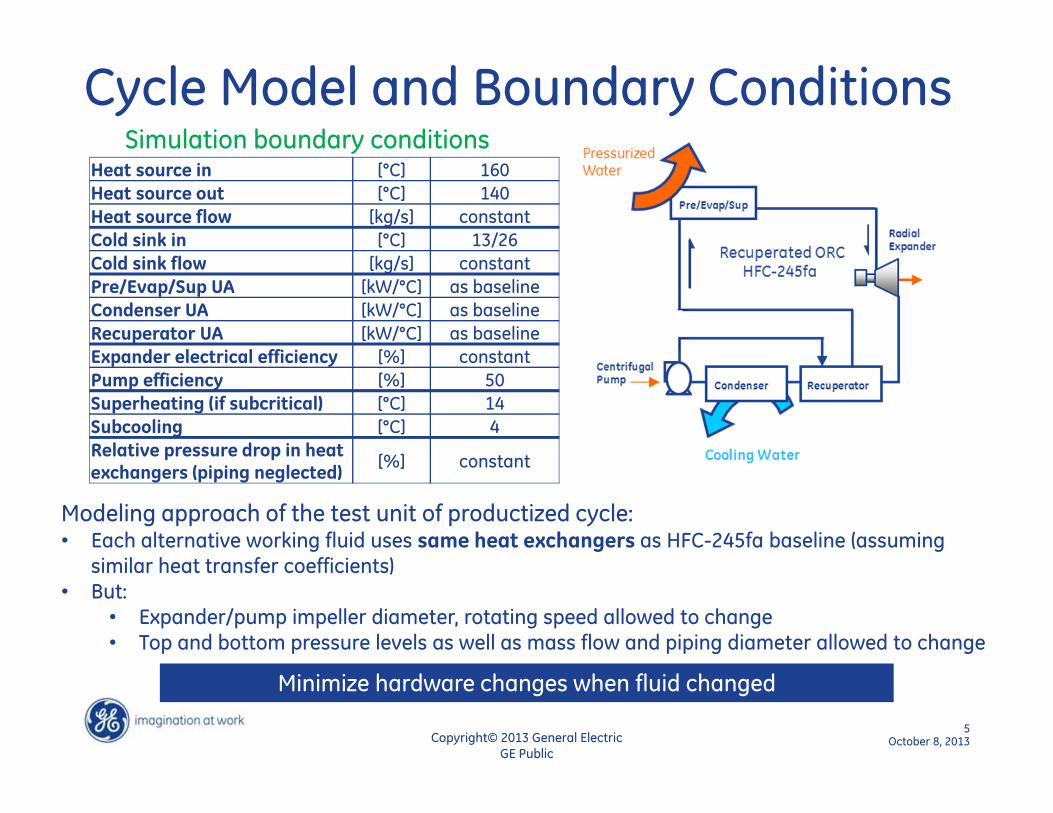
Cycle Model and Boundary Conditions
Heat source in [°C] 160
Heat source out [°C] 140
Heat source flow [kg/s] constant
Cold sink in [°C] 13/26
Cold sink flow [kg/s] constant
Pre/Evap/Sup UA [kW/°C] as baseline
Condenser UA [kW/°C] as baseline
Recuperator UA [kW/°C] as baseline
Expander electrical efficiency [%] constant
Pump efficiency [%] 50
Superheating (if subcritical) [°C] 14
Subcooling [°C] 4
Relative pressure drop in heat exchangers (piping neglected)
[%] constant
Simulation boundary conditions
Modeling approach of the test unit of productized cycle:• Each alternative working fluid uses same heat exchangers as HFC-245fa baseline (assuming
similar heat transfer coefficients)• But:
• Expander/pump impeller diameter, rotating speed allowed to change• Top and bottom pressure levels as well as mass flow and piping diameter allowed to change
Minimize hardware changes when fluid changed
Copyright© 2013 General ElectricGE Public

@#GECON&*6
October 8, 2013
Modeling Results-Net Power Output
• HCFO-1233zd(E) results in slight cycle net electrical power increase (2%)
• HFO-1234yf and HFO-1234ze(E) result in significant cycle net electrical power decrease. More adequate for HFC-134a replacement
Heat sink temperature at 26°C. Similar trend at 13°C
Only HCFO-1233zd(E) further considered
Copyright© 2013 General ElectricGE Public

@#GECON&*7
October 8, 2013
Modeling Results-Detailed Comparison
HCFO-1233zd(E) is an attractive alternative to HFC-245fa.Drop-in replacement seems possible.
Assumption was validated experimentally
• Increase of cycle net electrical power mostly driven by lower pumping power (slight increase of mass flow at lower top pressure)
• Limited changes in key expander parameters
Fluid [-] HFC-245fa HCFO-1233zd(E)
Cycle net electrical power [%] 100.0 102.2
Expander shaft power [%] 100.0 100.6
Pump shaft power [%] 100.0 89.2
Mass flow total [%] 100.0 102.2
Expander
Expander inlet temperature [%] 100.0 99.6
Expander inlet pressure [%] 100.0 84.6
Condenser
Volume flow inlet [%] 100.0 118.9
Outlet pressure (26°C cooling water)
[bar] 2.45 2.09
Outlet pressure (13°C cooling water)
[bar] 1.47 1.26
Fluid [-] HFC-245fa HCFO-1233zd(E)
Inlet area: mass flow/(density*speed of sound)
[%] 100.0 121.6
Pressure ratio [-] 7.8 7.7
Wheel diameter: Qout^0.5/H^0.25 [%] 100.0 107.4
Speed: H^0.75/Qout^0.5 [%] 100.0 94.7
• Maximum volume flow increased: larger pipe diameter required
• Minimum operating pressure above atmospheric: no air ingestion
Copyright© 2013 General ElectricGE Public

@#GECON&*8
October 8, 2013
Testing Procedure
• Use of a test unit of a productized ORC• Drop-in test: all components, including radial
expander, remained unchanged and as designed as for HFC-245fa
• Operational safety controls adjusted because of fluid property differences
Operating Regime Low Normal High
Cycle net grid power 71%, 86% 100%, 114% 124%, 133%
Expander inlet temperature 97% 100% 111%
Expander rotating speed 95% 100% 105%
• Test matrix covering large operating range for HFC-245fa and HCFO-1233zd(E)
Drop-in replacement test.Different from simulation approach
Cooling water temperature and mass flow kept constant
Copyright© 2013 General ElectricGE Public

@#GECON&*9
October 8, 2013
Experimental Results 1/2
• Pressure level lower with HCFO-1233zd(E)• 1.5bar lower at expander inlet for the same
inlet temperature
• 0.5bar lower at expander outlet
• Expander pressure ratio higher with HCFO-1233zd(E)• Based on saturation properties, HFC-245fa PR
between two isotherms should be higher
• But HCFO-1233zd(E) operates w/ lower
superheating (relatively higher inlet pressure)
and lower condensing temperature than HFC-
245fa (relatively lower outlet pressure, over-
dimensioned condenser)
• Expander electrical efficiency more than 5% pts higher with HCFO-1233zd(E)• Higher pressure ratio allows operating in a
higher adiabatic efficiency region of the
expander curve than with HFC-245fa
• Operating HFC-245fa in this region would
result in a lower overall cycle net efficiency
Copyright© 2013 General ElectricGE Public

@#GECON&*10
October 8, 2013
Experimental Results 2/2
Additional results• Dynamic behavior: similar time to reach steady-state (+/-5kW electrical power over 5
minutes) from start-up and shut-down to steady-state• Fluid thermal stability: post-analysis with gas chromatography–mass spectrometry
showed no sign of decomposition (limited run time of 72 hours) • Material compatibility: silicone o-rings and seals used for HFC-245fa maintained integrity
(limited run time)
• Grouping depending on expander inlet temperature
• Statistical analysis on complete population of experimental points incl. uncertainties concluded there is no significant difference in cycle net electrical efficiency between HFC-245fa and HCFO-1233zd(E) • Although HCFO-1233zd(E) expander
electrical efficiency higher, parasitic
load also higher
• Larger volume flow in same pipes
result in relative increase of pressure
drop and pumping power
Low and medium expander inlet temperature
High expander inlet temperature
Copyright© 2013 General ElectricGE Public

@#GECON&*11
October 8, 2013
Conclusion and Next Steps• Cycle simulation effort down-selected HCFO-1233zd(E) as the working fluid that
best matched the performance of HFC-245fa • Experimental results showed that HFO-1233zd(E), when used as a drop-in
replacement fluid in a cycle originally designed for HFC-245fa, consistently results in similar cycle net electrical efficiency
• As a low GWP and non-flammable working fluid, HCFO-1233zd(E) is therefore a viable candidate as a drop-in replacement fluid to HFC-245fa for the considered productized unit
Next steps• Long term testing• ORC optimized for HCFO-1233zd(E)
• Simulation and experiments indicates it could outperform HFC-245fa• Thermal stability and material compatibility at higher temperature
• HCFO-1233zd(E) was run at a maximum of 150°C• Comparison w/ other proposed LGWP fluids
• Other hydrofluoroolefins• Hydrofluoroketones
Copyright© 2013 General ElectricGE Public

@#GECON&*12
October 8, 2013
AcknowledgmentWe would like to acknowledge Ryan Hulse and Gary Zyhowski at Honeywell for their support throughout simulation and experimental investigations. Additional GE members that supported the experiments: Edip Sevincer, Huijuan (June) Chen, Ajilli Hardy and Chiranjeev Kalra, Rick Piel, Matteo Giovanetti, Tom Rising, Vinoth Rengarajanand Edward Fichtel.
Disclaimer“This report was prepared as an account of work sponsored by an agency of the United States Government. Neither the U.S. Government nor any agency thereof, nor any of their employees, makes any warranty, express or implied, or assumes any legal liability of responsibility for the accuracy, completeness, or usefulness of any information, apparatus, product, or process disclosed, or represents that its use would not infringe privately owned rights. Reference herein to any specific commercial product, or process, or serviceable by trade name, trademark, manufacture, or otherwise does not necessarily constitute or imply its endorsement, recommendation, or favoring by the U.S. Government or any agency thereof. The views and opinions of authors expressed herein do not necessarily state of reflect those of the U.S. Government or any agency thereof.”
Copyright© 2013 General ElectricGE Public

@#GECON&*13
October 8, 2013
Thank you.
Copyright© 2013 General ElectricGE Public