Embed Size (px)
DESCRIPTION
ASME Y14.5 2009 Manual
Citation preview
Copyright © 2004 - 2009 by Multi Metrics, Inc. Menlo Park, CA All Rights Reserved
by
Bill Tandler
A SmartGD&T™ Workshop
SmartGD&TIntroductory Remarks
TM
for the
Carl Zeiss CMM User Group Meeting 2009

Copyright © 2004 - 2009 by Multi Metrics, Inc. Menlo Park, CA All Rights Reserved
Workshop Overview
1. What is GD&T? – A Reminder2. Fundamental GD&T Concepts3. Feature Control Frames: Structure & Decoding4. The Datum Reference Frame Establishment
Process in Concept and using CMM Software
SmartGD&T™
Copyright © 2004 - 2009 by Multi Metrics, Inc. Menlo Park, CA All Rights Reserved
What is GD&T ?

Copyright © 2004 - 2009 by Multi Metrics, Inc. Menlo Park, CA All Rights Reserved
Grim, Depressing & Troublesome
Many people think “GD&T” stands for
or
Greatest Design Tool ever !

Copyright © 2004 - 2009 by Multi Metrics, Inc. Menlo Park, CA All Rights Reserved
Perfectly!
and it’s the only tool we have for
managing imperfect geometry
But of course, GD&T stands for
Geometric Dimensioning & Tolerancing

Copyright © 2004 - 2009 by Multi Metrics, Inc. Menlo Park, CA All Rights Reserved
Most people would say . . .The main purpose of GD&T is to communicate Design intent unambiguously to manufacturing and inspection.
Definition
but in fact . . .The primary purpose of GD&T, is to ensure that what we communicate is worth communicating . . . . namely represents functional, assemblable parts.

Copyright © 2004 - 2009 by Multi Metrics, Inc. Menlo Park, CA All Rights Reserved
In fact ….
without GD&Tall coordinate metrology must remain
Pure Inventionon the part of the inspector

Copyright © 2004 - 2009 by Multi Metrics, Inc. Menlo Park, CA All Rights Reserved
How about the GD&T tool kit?It consists of:
Geometry Control ToolsFeature Control FramesBasic Dimensions, andDatum Feature Labels

Copyright © 2004 - 2009 by Multi Metrics, Inc. Menlo Park, CA All Rights Reserved
1. Tolerance ZonesBounded regions of space within which feature components are required to lie.
2. Tolerance ValuesThe sizes of tolerance zones.
3. DatumsReference points, lines and planes.
4. Coordinate SystemsFrames of reference for orienting and locating tolerance zones.
5. Basic DimensionsTools for orienting and locating tolerance zones.
6. Geometry Control ToolsA symbolic language for imposing the perfect imaginary world on the imperfect real world.
TZ Wall ThicknessTZ Diameter
TZ Thickness
The Perfect Imaginary World of GD&T
Tube-like
Cylindrical
Slab-like

Copyright © 2004 - 2009 by Multi Metrics, Inc. Menlo Park, CA All Rights Reserved
The imperfect actual part!
The actual part embedded in its associated tolerance zones
The coordinate system and tolerance zone “forest” defined by the GD&T Code
The encoded CAD Model GD&T at Work

Copyright © 2004 - 2009 by Multi Metrics, Inc. Menlo Park, CA All Rights Reserved
1. Datum Features2. Datum Feature Simulators3. Datums4. Datum Reference Frames5. Basic Dimensions6. Material Condition Modifiers7. Actual Values
Fundamental Concepts

Copyright © 2004 - 2009 by Multi Metrics, Inc. Menlo Park, CA All Rights Reserved
Physical Datum FeaturesImportant Concepts
Definition:
Datum Features are specially labeled, imperfect, physical features of a real part, which serve to constrain degrees of rotational and translational freedom during assembly processes.

Copyright © 2004 - 2009 by Multi Metrics, Inc. Menlo Park, CA All Rights Reserved
Substitute Datum FeaturesImportant Concepts
The CMM Connection:
Coordinate Metrology systems use geometry processing algorithms to extract form-perfect substitute Datum Features from actual Datum Features.

Copyright © 2004 - 2009 by Multi Metrics, Inc. Menlo Park, CA All Rights Reserved
Substitute Datum FeaturesImportant Concepts
SubstituteDatum Feature A
Alternatives:
1. Least squares plane2. Mid-plane of the minimum slab-like zone3. In-space, surface of the minimum slab-like zone4. In-space, force constrained tangent plane

Copyright © 2004 - 2009 by Multi Metrics, Inc. Menlo Park, CA All Rights Reserved
Important Concepts
1. Unconstrained, maximum inscribed cylinder2. Least squares cylinder3. In-space surface of the minimum tube-like zone
Substitute Datum Features
SubstituteDatum Feature B
Alternatives:

Copyright © 2004 - 2009 by Multi Metrics, Inc. Menlo Park, CA All Rights Reserved
Important Concepts
1. Mid-plane of two least squares planes2. Mid-plane of the in-space boundary planes of
two minimum slab-like zones
Substitute Datum Features
SubstituteDatum Feature C
Alternatives:

Copyright © 2004 - 2009 by Multi Metrics, Inc. Menlo Park, CA All Rights Reserved
1. Datum Features2. Datum Feature Simulators3. Datums4. Datum Reference Frames5. Basic Dimensions6. Material Condition Modifiers7. Actual Values
More Important Concepts

Copyright © 2004 - 2009 by Multi Metrics, Inc. Menlo Park, CA All Rights Reserved
Datum Feature SimulatorsDefinition:
The conceptually perfect, or physically almost perfect, geometric counterparts of Datum Features, which are beholden to the Rules of Datum Feature Simulator Management, and:
Important Concepts
1. from which we extract Datums
2. in which we first establish Datum Reference Frames, and
3. with which we transfer Datum Reference Frames to actual parts.

Copyright © 2004 - 2009 by Multi Metrics, Inc. Menlo Park, CA All Rights Reserved
Physical Datum Feature SimulatorsImportant Concepts
PlanarDatum Feature Simulator
AExpanding Cylindrical
Datum Feature Simulator B
Fixed “Tombstone”Datum Feature Simulator
C

Copyright © 2004 - 2009 by Multi Metrics, Inc. Menlo Park, CA All Rights Reserved
Important Concepts
The CMM Connection:
Coordinate Metrology systems use geometry processing algorithms to extract form, and potentially size, orientation and location constrained, perfect, inverse substitute features from actual datum features and CAD models.
Mathematical Datum Feature Simulators

Copyright © 2004 - 2009 by Multi Metrics, Inc. Menlo Park, CA All Rights Reserved
Computer generated, size, orientation and location constrained, slab representing Datum Feature Simulator C
Important Concepts
Computer generated unconstrained, tangent planerepresenting Datum Feature Simulator A
Computer generated, orientation constrained, maximum inscribed, cylinder representing Datum Feature Simulator B
Mathematical Datum Feature Simulators
Copyright © 2004 - 2009 by Multi Metrics, Inc. Menlo Park, CA All Rights Reserved
1. Datum Features2. Datum Feature Simulators3. Datums4. Datum Reference Frames5. Basic Dimensions6. Material Condition Modifiers7. Actual Values
More Important Concepts

Copyright © 2004 - 2009 by Multi Metrics, Inc. Menlo Park, CA All Rights Reserved
Important Concepts
DatumsDefinition:
Datums are the minimum set of one perfect reference point, and/or straight line, and/or plane, which together, fully characterize the orientation and location of a datum feature simulator.
Datums serve to constrain the degrees of freedom of starter coordinate systems and turn them into
Datum Reference Frames.
Copyright © 2004 - 2009 by Multi Metrics, Inc. Menlo Park, CA All Rights Reserved
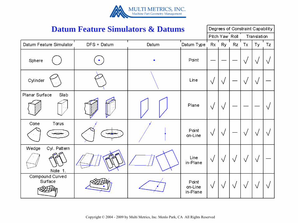
Datum Feature Simulators & Datums

Copyright © 2004 - 2009 by Multi Metrics, Inc. Menlo Park, CA All Rights Reserved
Datum C is the mid-plane ofDatum Feature Simulator C
Important Concepts
Datum A is the tangent plane onDatum Feature Simulator A
Datum B is the axis ofDatum Feature Simulator B
DatumsExtracted from Datum Feature Simulators

Copyright © 2004 - 2009 by Multi Metrics, Inc. Menlo Park, CA All Rights Reserved
Important Concepts
DatumsExtracted from Datum Features
The CMM Connection:
Coordinate Metrology systems often bypass the simulator step and use geometry processing algorithms to extract Datums directly from Datum Features. This is perfectly possible, but BEWARE !

Copyright © 2004 - 2009 by Multi Metrics, Inc. Menlo Park, CA All Rights Reserved
Important Concepts
DatumsExtracted from Datum Features
In fact, Datum B is the axis of the orientation constrained, maximum inscribed cylinder inside Datum Feature B
Case 1
What is Datum B ???Surely Datum B is the axis of the maximum inscribed cylinder inside Datum Feature B !
Right !
Wrong !

Copyright © 2004 - 2009 by Multi Metrics, Inc. Menlo Park, CA All Rights Reserved
Important Concepts
DatumsExtracted from Datum Features
In fact, Datum C is the mid-plane of the orientation & location constrained, virtual maximum material condition slab inside Datum Feature C.
Right !
What is Datum C ???
Wrong !
Surely Datum C is mid-plane of the maximum inscribed slab inside Datum Feature C

Copyright © 2004 - 2009 by Multi Metrics, Inc. Menlo Park, CA All Rights Reserved
Important Concepts
Question:
What do the letters in a Feature Control Frame represent:1. Datums ?2. Datum Features ?3. Datum Feature Simulators ?

Copyright © 2004 - 2009 by Multi Metrics, Inc. Menlo Park, CA All Rights Reserved
Important Concepts
Question Answer
Datum Features …. of course!
Points, lines and planes cannot be “simulated” regardless of their size, or simulated at their virtual Maximum Material Boundaries.

Copyright © 2004 - 2009 by Multi Metrics, Inc. Menlo Park, CA All Rights Reserved
1. Datum Features2. Datum Feature Simulators3. Datums4. Datum Reference Frames5. Basic Dimensions6. Material Condition Modifiers7. Actual Values
More Important Concepts

Copyright © 2004 - 2009 by Multi Metrics, Inc. Menlo Park, CA All Rights Reserved
Important Concepts
Datum Reference Frames
Definition:
Datum Reference Frames are Cartesian Coordinate Systems
established using Datums.

Copyright © 2004 - 2009 by Multi Metrics, Inc. Menlo Park, CA All Rights Reserved
Important Concepts
Datum Reference FramesIn the CAD Model
Copyright © 2004 - 2009 by Multi Metrics, Inc. Menlo Park, CA All Rights Reserved
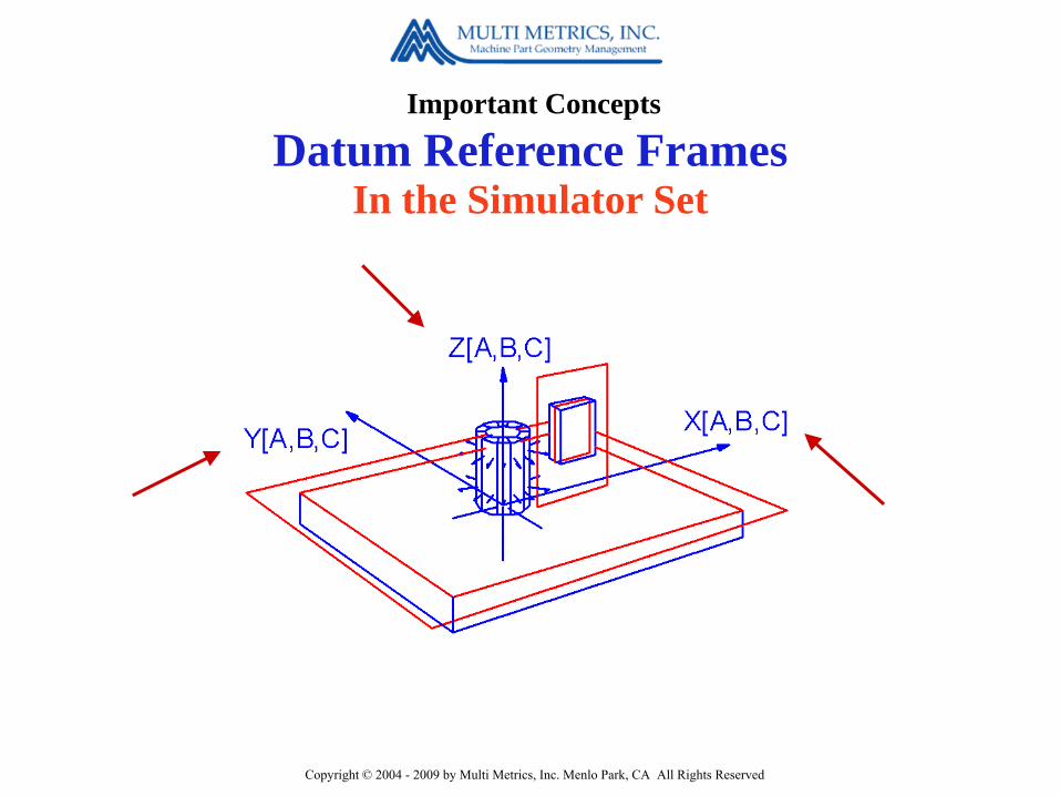
Important Concepts
Datum Reference FramesIn the Simulator Set

Copyright © 2004 - 2009 by Multi Metrics, Inc. Menlo Park, CA All Rights Reserved
Important Concepts
Datum Reference FramesIn the Actual Part

Copyright © 2004 - 2009 by Multi Metrics, Inc. Menlo Park, CA All Rights Reserved
1. Datum Features2. Datum Feature Simulators3. Datums4. Datum Reference Frames5. Basic Dimensions6. Material Condition Modifiers7. Actual Values
More Important Concepts

Copyright © 2004 - 2009 by Multi Metrics, Inc. Menlo Park, CA All Rights Reserved
Important Concepts
Basic Dimensions
Definition:
Basic dimensions are framed angular and linear dimensions, which serve to orient and locate tolerance zones, …..
…... but only those tolerance zones which can be oriented and located.

Copyright © 2004 - 2009 by Multi Metrics, Inc. Menlo Park, CA All Rights Reserved
Important Concepts
They locate the Position tolerance zone for the lower, right hand bore.
Basic Dimensions Case 1
What purpose do these basic dimensions serve?

Copyright © 2004 - 2009 by Multi Metrics, Inc. Menlo Park, CA All Rights Reserved
Important Concepts
Basic Dimensions Case 2
It locates the Position tolerance zone for the slot (Datum Feature C).
What purpose does this basic dimension serve?
Copyright © 2004 - 2009 by Multi Metrics, Inc. Menlo Park, CA All Rights Reserved
Important Concepts
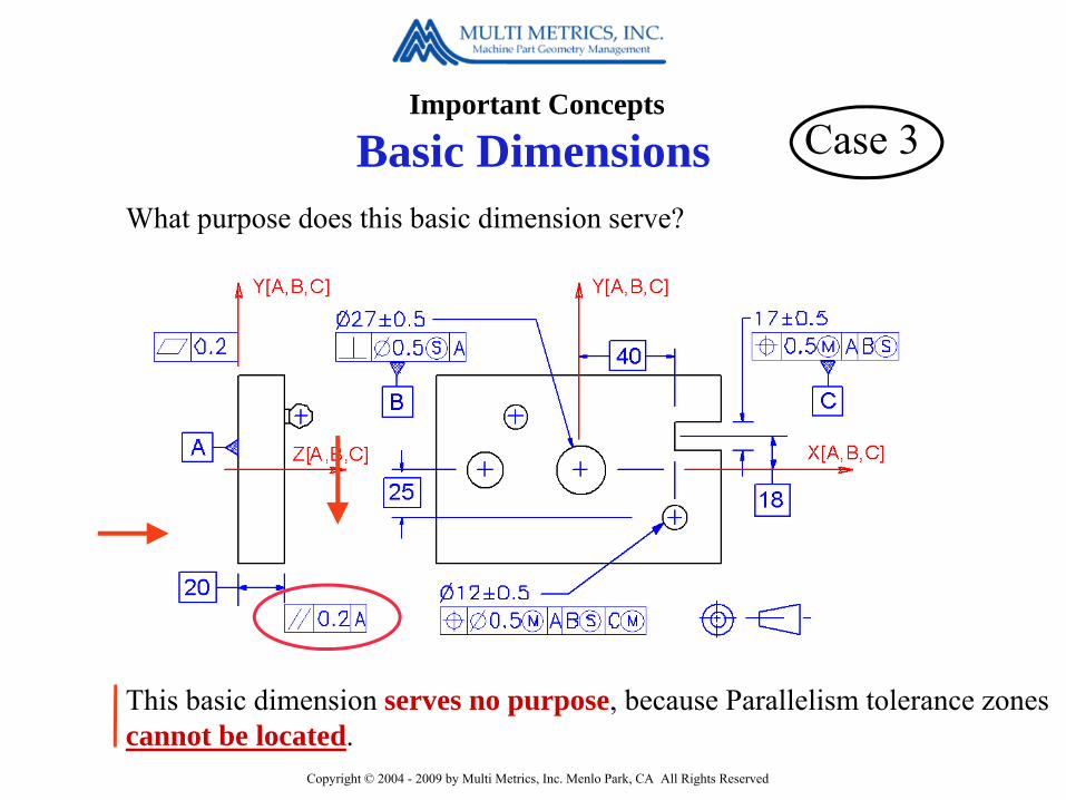
This basic dimension serves no purpose, because Parallelism tolerance zones cannot be located.
Basic Dimensions Case 3
What purpose does this basic dimension serve?
Copyright © 2004 - 2009 by Multi Metrics, Inc. Menlo Park, CA All Rights Reserved
1. Datum Features2. Datum Feature Simulators3. Datums4. Datum Reference Frames5. Basic Dimensions6. Material Condition Modifiers7. Actual Values
More Important Concepts
Copyright © 2004 - 2009 by Multi Metrics, Inc. Menlo Park, CA All Rights Reserved
Important Concepts
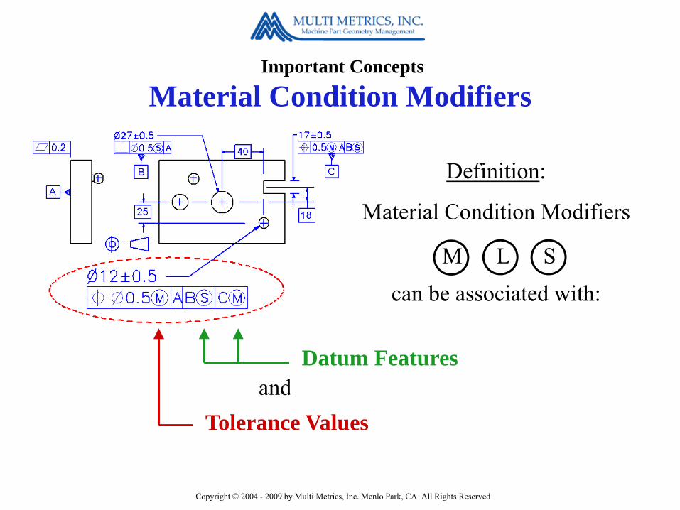
Material Condition Modifiers
Definition:
Material Condition Modifiers
can be associated with:
Datum Features
Tolerance Values
M L S
and

Copyright © 2004 - 2009 by Multi Metrics, Inc. Menlo Park, CA All Rights Reserved
Important Concepts
Material Condition Modifiers
M permits the tolerance zone to expand by as much as 1 mm as the bore departs from MMC toward LMC.
When associated withtolerance values they impact the size of a tolerance zone.

Copyright © 2004 - 2009 by Multi Metrics, Inc. Menlo Park, CA All Rights Reserved
Important Concepts
Material Condition Modifiers
S stabilizes the tolerance zone relative to Datum Feature B, regardless of its size.
When associated withDatum Features they impact the stability or mobility of a tolerance zone.

Copyright © 2004 - 2009 by Multi Metrics, Inc. Menlo Park, CA All Rights Reserved
Important Concepts
Material Condition Modifiers
M mobilizes the tolerance zone relative to Datum Feature C, as C departs from its Virtual MMC size.
When associated withDatum Features they impact the stability or mobility of a tolerance zone.

Copyright © 2004 - 2009 by Multi Metrics, Inc. Menlo Park, CA All Rights Reserved
1. Datum Features2. Datum Feature Simulators3. Datums4. Datum Reference Frames5. Basic Dimensions6. Material Condition Modifiers7. Actual Values
More Important Concepts

Copyright © 2004 - 2009 by Multi Metrics, Inc. Menlo Park, CA All Rights Reserved
Important Concepts
Actual Values
The Actual Value of a geometric characteristic is the size of the smallest associated tolerance zone that just accommodates the controlled component of the considered feature.
Definition:

Copyright © 2004 - 2009 by Multi Metrics, Inc. Menlo Park, CA All Rights Reserved
Important Concepts
Actual Values
What are the Actual Values of the Size of a bore?
Case 1
1. Actual Mating Size = the Diameter of the Maximum Inscribed Cylinder
2. Actual Local Size = the Diameter of the largest Minimum Circumscribed Circle

Copyright © 2004 - 2009 by Multi Metrics, Inc. Menlo Park, CA All Rights Reserved
Important Concepts
Actual Values Case 2
Actual Position = the Diameter of the location constrained, minimum circumscribed cylinder which just contains the bounded axis.
What is the Actual Value of the Position of a bore?

Copyright © 2004 - 2009 by Multi Metrics, Inc. Menlo Park, CA All Rights Reserved
Important Concepts
Actual Values Case 2

Copyright © 2004 - 2009 by Multi Metrics, Inc. Menlo Park, CA All Rights Reserved
Important Concepts
Actual Values Case 3
Actual Straightness = the Diameter of the smallest unconstrained cylinder which just contains all the points in the Median Line.
What is the Actual Value of the Straightness of a bore?

Copyright © 2004 - 2009 by Multi Metrics, Inc. Menlo Park, CA All Rights Reserved
What’s the
TheMeasured Value
of a Geometric Characteristic is the measuring uncertainty limited
Actual Value
Measured Value ?
Copyright © 2004 - 2009 by Multi Metrics, Inc. Menlo Park, CA All Rights Reserved
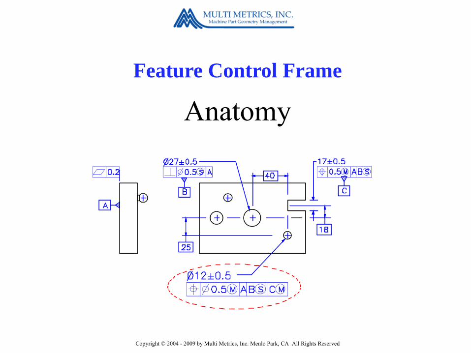
Feature Control Frame
Anatomy
Copyright © 2004 - 2009 by Multi Metrics, Inc. Menlo Park, CA All Rights Reserved
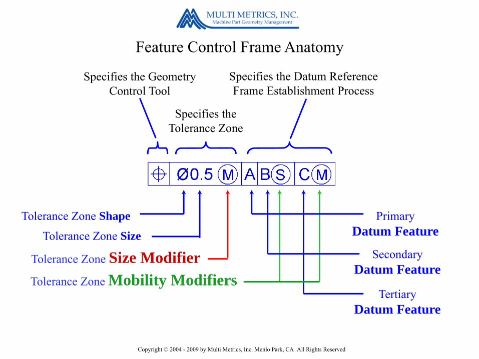
Feature Control Frame Anatomy
Specifies the Geometry Control Tool
Tolerance Zone Size Modifier
Specifies the Tolerance Zone
Tolerance Zone Mobility Modifiers
Specifies the Datum Reference Frame Establishment Process
PrimaryDatum Feature
SecondaryDatum Feature
TertiaryDatum Feature
Tolerance Zone Shape
Tolerance Zone Size

Copyright © 2004 - 2009 by Multi Metrics, Inc. Menlo Park, CA All Rights Reserved
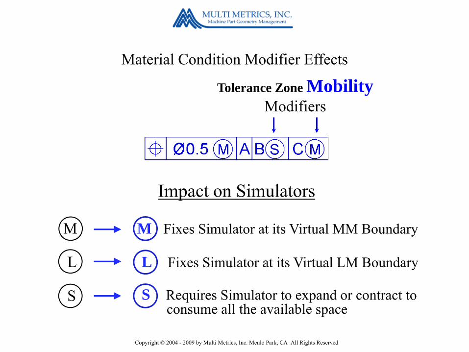
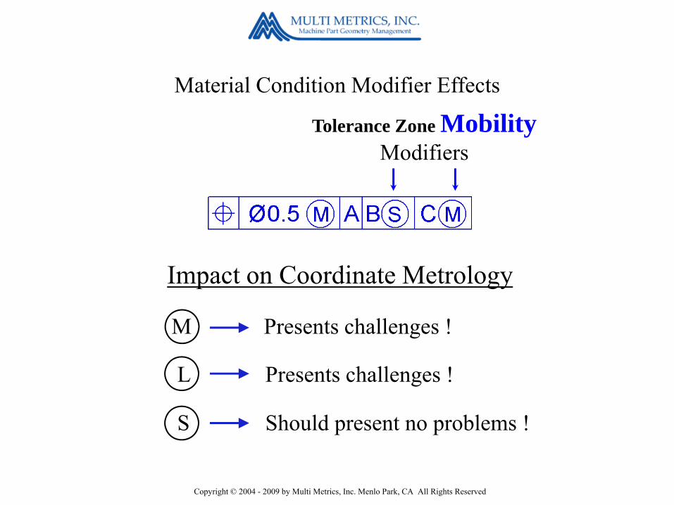
Material Condition Modifier Effects
Tolerance Zone SizeModifiers
M ore tolerance
L ots of tolerance
S tuck at 0.5 mm
M
L
S
Impact on Tolerance Zone Encoded Function
Feature Clearance
Feature Overlap
Feature Centering

Copyright © 2004 - 2009 by Multi Metrics, Inc. Menlo Park, CA All Rights Reserved
Material Condition Modifier Effects
Tolerance Zone SizeModifiers
Easy to implement, and generally well managed !
Easy to implement, but is it truly understood ?
Easy to implement – nothing to do !
M
L
S
Impact on Coordinate Metrology
Copyright © 2004 - 2009 by Multi Metrics, Inc. Menlo Park, CA All Rights Reserved
Tolerance Zone MobilityModifiers
M Fixes Simulator at its Virtual MM Boundary
L Fixes Simulator at its Virtual LM Boundary
S Requires Simulator to expand or contract to consume all the available space
M
L
S
Material Condition Modifier Effects
Impact on Simulators

Copyright © 2004 - 2009 by Multi Metrics, Inc. Menlo Park, CA All Rights Reserved
Tolerance Zone MobilityModifiers
M obilizes the tolerance zone
L oosens the tolerance zone
S tabilizes the tolerance zone
M
L
S
Material Condition Modifier Effects
Impact on DRF & Tolerance Zone Encoded Function
Mating Part play, guaranteeing clearance
Mating Part play, guaranteeing overlap
Mutual Centering
{{
Copyright © 2004 - 2009 by Multi Metrics, Inc. Menlo Park, CA All Rights Reserved
Tolerance Zone MobilityModifiers
Material Condition Modifier Effects
Presents challenges !
Presents challenges !
Should present no problems !
M
L
S
Impact on Coordinate Metrology

Copyright © 2004 - 2009 by Multi Metrics, Inc. Menlo Park, CA All Rights Reserved
Decoding GD&Tas opposed to
Interpreting GD&T
Now we’ll illustrate

Copyright © 2004 - 2009 by Multi Metrics, Inc. Menlo Park, CA All Rights Reserved
Position - within a diameter of 0.5 mm at MMC - relative to A, B regardless of feature size, and C at MMC.
Reading the Feature Control Frame.

Copyright © 2004 - 2009 by Multi Metrics, Inc. Menlo Park, CA All Rights Reserved
Position requires the bounded axis of the Considered Feature to lie within a cylindrical tolerance zone diameter of 0.5 mm at MMC - expanding by as much as 1 mm as the Considered Feature departs from MMC toward LMC -
Decoding the Feature Control Frame.

Copyright © 2004 - 2009 by Multi Metrics, Inc. Menlo Park, CA All Rights Reserved
- oriented and located by BASIC dimensions - relative to a Datum Reference Frame established using Datum Feature A, simulated rocking, Datum Feature B, simulated stably, regardless of its size, and Datum Feature C, simulated mobly, at its Virtual Maximum Material Condition size.
Decoding the Feature Control Frame.

Copyright © 2004 - 2009 by Multi Metrics, Inc. Menlo Park, CA All Rights Reserved
Namely this Datum Reference Frame !
Copyright © 2004 - 2009 by Multi Metrics, Inc. Menlo Park, CA All Rights Reserved
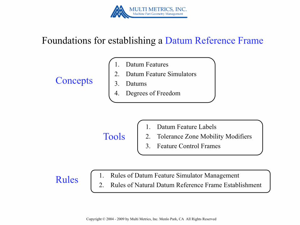
1. Datum Features2. Datum Feature Simulators3. Datums4. Degrees of Freedom
Concepts
1. Datum Feature Labels2. Tolerance Zone Mobility Modifiers3. Feature Control Frames
Tools
Rules 1. Rules of Datum Feature Simulator Management2. Rules of Natural Datum Reference Frame Establishment
Foundations for establishing a Datum Reference Frame

Copyright © 2004 - 2009 by Multi Metrics, Inc. Menlo Park, CA All Rights Reserved
Rules of Datum Feature Simulator Management
1. Form: All simulators shall have perfect form.
2. Orientation: All simulators shall be perfectly oriented by their associated basic dimensions.
3. Location: Unless otherwise indicated, all simulators shall be perfectly located by their associated basic dimensions.
4. Size: - Simulators referenced RFS shall expand or contract to consume all the space available in or outside their associated Datum Features. - Simulators referenced MMC or LMC shall be fixed at the Virtual MMC or LMC size of their associated Datum Features.

Copyright © 2004 - 2009 by Multi Metrics, Inc. Menlo Park, CA All Rights Reserved
1. Datum Feature Precedence: Datum Features shall be used in the order in which they appear in the Feature Control Frame.
2. Degrees of Constraint Precedence: Each Datum Feature shall first attempt to constrain pitch & yaw, then roll, and only then translational degrees of freedom.
3. Non-Override: No Datum Feature may impact degrees of freedom constrained by higher precedence Datum Features.
4. Can-May-Must: - If a Datum Feature can constrain a degree of freedom, and also may, then it must.
Rules of Natural Datum Reference Frame Establishment

Copyright © 2004 - 2009 by Multi Metrics, Inc. Menlo Park, CA All Rights Reserved
Step 1.Decode the Feature
Control Frame
Step 2.Identify the Datum
Features
Step 3.Construct the Datum Feature Simulators
Step 4.Extract the Datums from the Simulators
Step 5.Use the Datums to constrain a
starter coordinate system in the Simulators
Step 6.Transfer the DRF to the
part by mating the Datum Features with their
simulators
A: planar surface
Expanding Cylindrical Simulator B
Virtual MMCTombstone Simulator C
Planar Simulator A
The Six Step Datum Reference Frame Establishment Process
B: hollow cylinderC: slot
Copyright © 2004 - 2009 by Multi Metrics, Inc. Menlo Park, CA All Rights Reserved
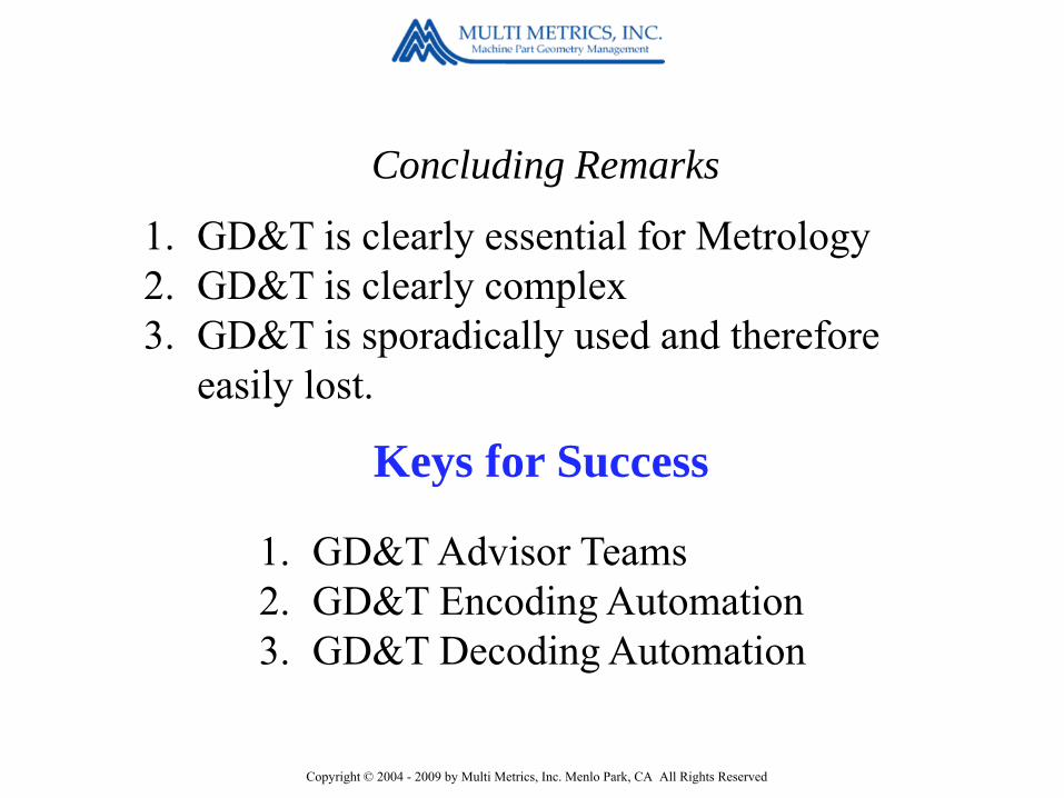
Concluding Remarks
1. GD&T is clearly essential for Metrology2. GD&T is clearly complex3. GD&T is sporadically used and therefore
easily lost.
1. GD&T Advisor Teams2. GD&T Encoding Automation3. GD&T Decoding Automation
Keys for Success
Copyright © 2004 - 2009 by Multi Metrics, Inc. Menlo Park, CA All Rights Reserved
by
Bill Tandler
A SmartGD&T Overview
Updated 2009-10-29
The NewASME Y14.5 2009 Standard
TM
for the
Carl Zeiss CMM User Group Meeting 2009

Copyright © 2004 - 2009 by Multi Metrics, Inc. Menlo Park, CA All Rights Reserved
Tutorial Overview
1. “What is GD&T?” - A Reminder2. New Concepts3. New Tools Impacting Datums4. New Tools Impacting Tolerance Zones5. Disappointments
SmartGD&T™

Copyright © 2004 - 2009 by Multi Metrics, Inc. Menlo Park, CA All Rights Reserved
Most people would say . . .The main purpose of GD&T is to communicate Design intent unambiguously to manufacturing and inspection.
“What is GD&T?” A Reminder
but in fact . . .The primary purpose of GD&T, is to ensure that what we communicate is worth communicating . . . . namely represents functional, assemblable parts.

Copyright © 2004 - 2009 by Multi Metrics, Inc. Menlo Park, CA All Rights Reserved
1. Design
2. Manufacturing
3. Inspection
4. Assembly
is a risk management tool for . . .
GD&T
Copyright © 2004 - 2009 by Multi Metrics, Inc. Menlo Park, CA All Rights Reserved
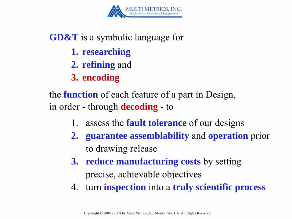
GD&T is a symbolic language for1. researching2. refining and3. encoding
the function of each feature of a part in Design,in order - through decoding - to
1. assess the fault tolerance of our designs2. guarantee assemblability and operation prior
to drawing release3. reduce manufacturing costs by setting
precise, achievable objectives4. turn inspection into a truly scientific process
Copyright © 2004 - 2009 by Multi Metrics, Inc. Menlo Park, CA All Rights Reserved
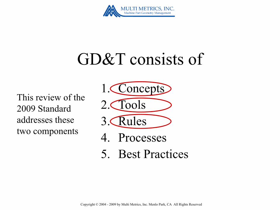
1. Concepts2. Tools3. Rules4. Processes5. Best Practices
GD&T consists of
This review of the 2009 Standard addresses these two components
Copyright © 2004 - 2009 by Multi Metrics, Inc. Menlo Park, CA All Rights Reserved
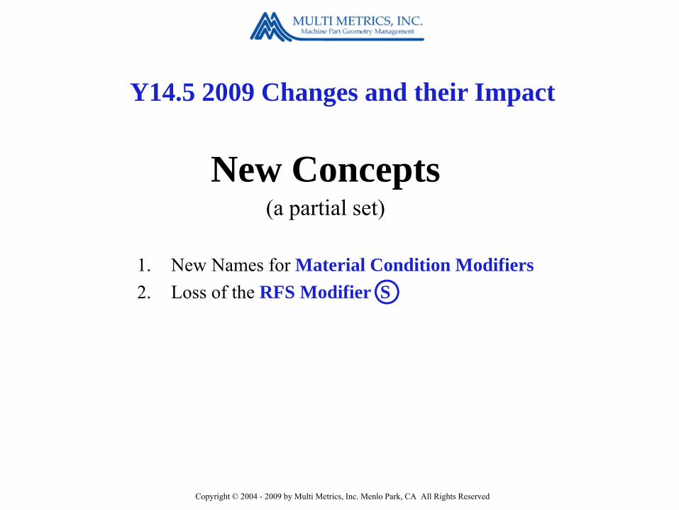
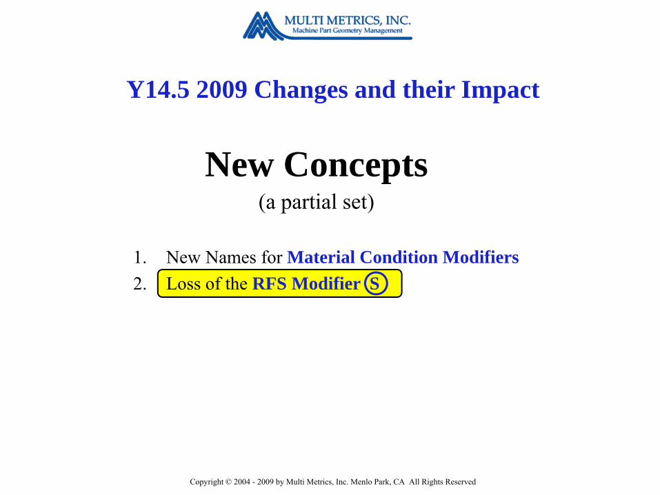
1. New Names for Material Condition Modifiers2. Loss of the RFS Modifier S
Y14.5 2009 Changes and their Impact
New Concepts(a partial set)
Copyright © 2004 - 2009 by Multi Metrics, Inc. Menlo Park, CA All Rights Reserved
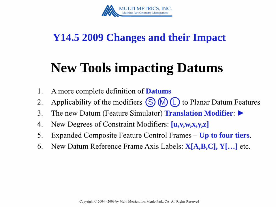
Y14.5 2009 Changes and their Impact
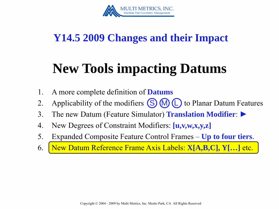
New Tools impacting Datums1. A more complete definition of Datums2. Applicability of the modifiers S M L to Planar Datum Features3. The new Datum (Feature Simulator) Translation Modifier: ►4. New Degrees of Constraint Modifiers: [u,v,w,x,y,z]5. Expanded Composite Feature Control Frames – Up to four tiers.6. New Datum Reference Frame Axis Labels: X[A,B,C], Y[…] etc.
Copyright © 2004 - 2009 by Multi Metrics, Inc. Menlo Park, CA All Rights Reserved
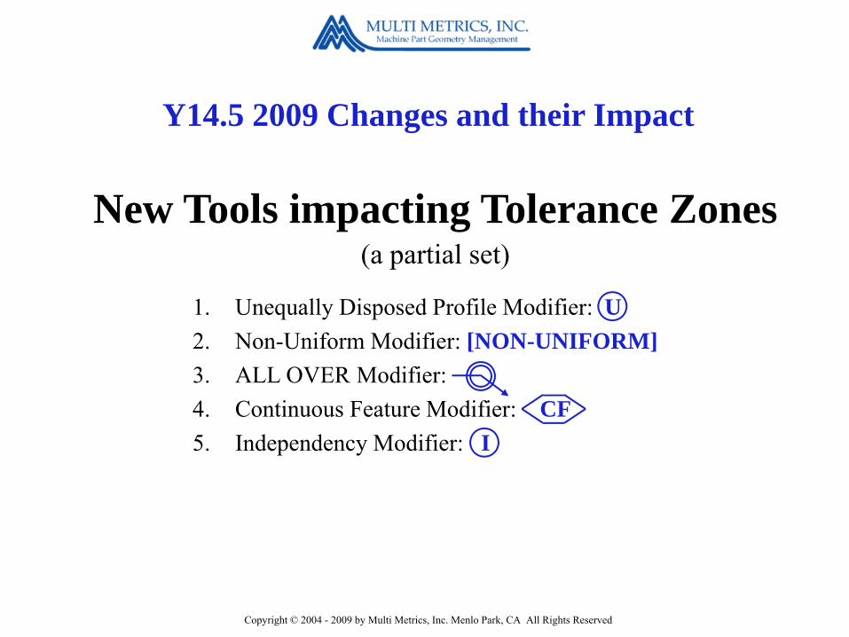
Y14.5 2009 Changes and their Impact
1. Unequally Disposed Profile Modifier: U2. Non-Uniform Modifier: [NON-UNIFORM]3. ALL OVER Modifier: 4. Continuous Feature Modifier: CF5. Independency Modifier: I
New Tools impacting Tolerance Zones(a partial set)

Copyright © 2004 - 2009 by Multi Metrics, Inc. Menlo Park, CA All Rights Reserved
Y14.5 2009 Changes and their Impact
Disappointments1. Still no clearly defined, accessible, sets of Rules.2. The Concentricity and Symmetry tools unchanged.3. The Radius and Controlled Radius Tools still define
non-functional crescent shaped tolerance zones.4. Still no tool for controlling the orientation and location
of curved “spines”.5. Still no page number references in the index.

Copyright © 2004 - 2009 by Multi Metrics, Inc. Menlo Park, CA All Rights Reserved
1. New Names for Material Condition Modifiers2. Loss of the RFS Modifier S
Y14.5 2009 Changes and their Impact
New Concepts(a partial set)

Copyright © 2004 - 2009 by Multi Metrics, Inc. Menlo Park, CA All Rights Reserved
If all these modifiers are called“Material Condition” Modifiers
how can we differentiate between their effects?
New Names for Material Condition Modifiers

Copyright © 2004 - 2009 by Multi Metrics, Inc. Menlo Park, CA All Rights Reserved
New Names for Material Condition Modifiers
The Great Divide
MobilityThese modifiers impact Tolerance Zone Size
“Tolerance Value”Modifiers “Material Boundary”
Modifiers
These modifiers impact Tolerance Zone
New 2009 Name
New 2009 Name
Copyright © 2004 - 2009 by Multi Metrics, Inc. Menlo Park, CA All Rights Reserved
New Names for Material Condition Modifiers
Here are our favorites
It’s great to finally highlight the differences,
but the names could be better.

Copyright © 2004 - 2009 by Multi Metrics, Inc. Menlo Park, CA All Rights Reserved
New Names for Material Condition Modifiers
The Great Divide
MobilityThese modifiers impact Tolerance Zone Size
“Tolerance Zone Size”Modifiers
“Tolerance Zone Mobility”Modifiers
These modifiers impact Tolerance Zone
the SmartGD&T recommended names
Copyright © 2004 - 2009 by Multi Metrics, Inc. Menlo Park, CA All Rights Reserved
1. New Names for Material Condition Modifiers2. Loss of the RFS Modifier S
Y14.5 2009 Changes and their Impact
New Concepts(a partial set)
Copyright © 2004 - 2009 by Multi Metrics, Inc. Menlo Park, CA All Rights Reserved
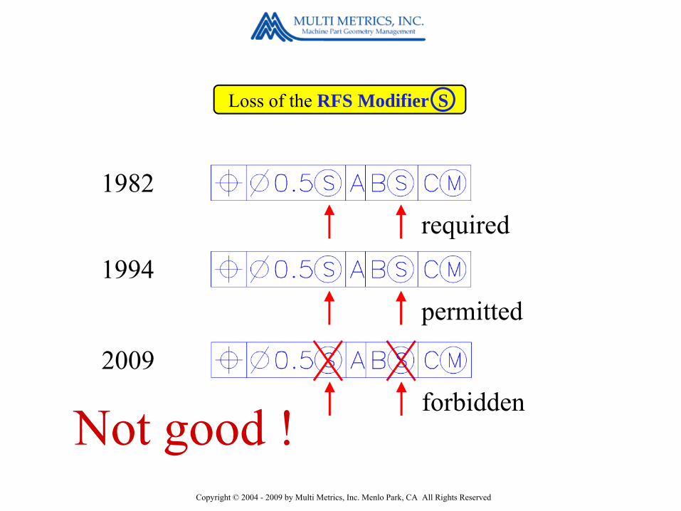
Loss of the RFS Modifier S
1982required
1994permitted
2009forbidden
Not good !
Copyright © 2004 - 2009 by Multi Metrics, Inc. Menlo Park, CA All Rights Reserved
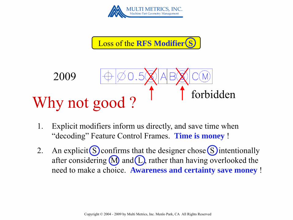
Loss of the RFS Modifier S
Why not good ?
2009forbidden
1. Explicit modifiers inform us directly, and save time when “decoding” Feature Control Frames. Time is money !
2. An explicit S confirms that the designer chose S intentionally after considering M and L , rather than having overlooked the need to make a choice. Awareness and certainty save money !

Copyright © 2004 - 2009 by Multi Metrics, Inc. Menlo Park, CA All Rights Reserved
Loss of the RFS Modifier S
Retaining an explicit S is therefore highly recommended !
You can do so with a corporate document specifying it as a corporate modification to the Standard, or with a note, both very common practices in industry.
2009

Copyright © 2004 - 2009 by Multi Metrics, Inc. Menlo Park, CA All Rights Reserved
Y14.5 2009 Changes and their Impact
New Tools impacting Datums1. A more complete definition of Datums2. Applicability of the modifiers S M L to Planar Datum Features3. The new Datum (Feature Simulator) Translation Modifier: ►4. New Degrees of Constraint Modifiers: [u,v,w,x,y,z]5. Expanded Composite Feature Control Frames – Up to four tiers.6. New Datum Reference Frame Axis Labels: X[A,B,C], Y[…] etc.
Copyright © 2004 - 2009 by Multi Metrics, Inc. Menlo Park, CA All Rights Reserved
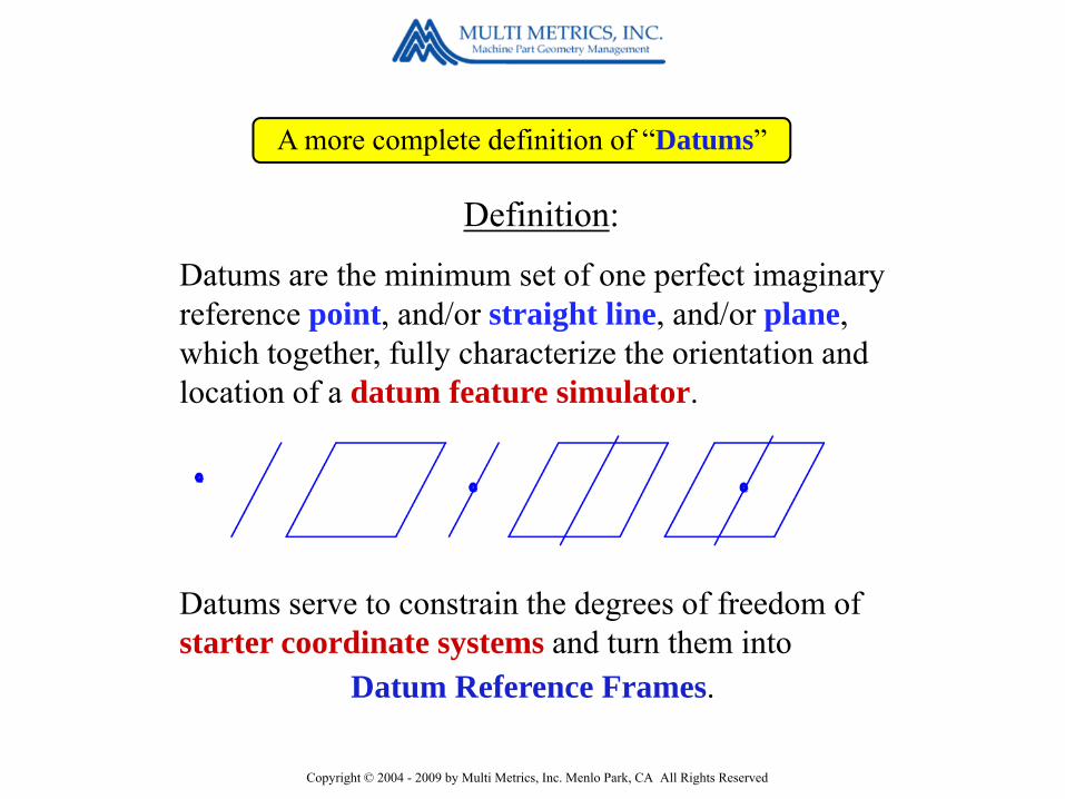
Definition:
Datums are the minimum set of one perfect imaginary reference point, and/or straight line, and/or plane, which together, fully characterize the orientation and location of a datum feature simulator.
Datums serve to constrain the degrees of freedom of starter coordinate systems and turn them into
A more complete definition of “Datums”
Datum Reference Frames.

Copyright © 2004 - 2009 by Multi Metrics, Inc. Menlo Park, CA All Rights Reserved
Datum Feature Simulators & Datums

Copyright © 2004 - 2009 by Multi Metrics, Inc. Menlo Park, CA All Rights Reserved
1. A more complete definition of Datums2. Applicability of the modifiers S M L to Planar Datum Features3. The new Datum (Feature Simulator) Translation Modifier: ►4. New Degrees of Constraint Modifiers: [u,v,w,x,y,z]5. Expanded Composite Feature Control Frames – Up to four tiers.6. New Datum Reference Frame Axis Labels: X[A,B,C], Y[…] etc.
Y14.5 2009 Changes and their Impact
New Tools impacting Datums

Copyright © 2004 - 2009 by Multi Metrics, Inc. Menlo Park, CA All Rights Reserved
C is a planar surface.
Applicability of the modifiers S M L to Planar Datum Features
Prior to 2009, the Tolerance Zone Mobility modifiers S M and L could not be applied to planar surfaces !

Copyright © 2004 - 2009 by Multi Metrics, Inc. Menlo Park, CA All Rights Reserved
If C is a location constrained planar
Datum Feature,TZM
modifiers are now allowed
Applicability of the modifiers S M L to Planar Datum Features
The 2009 Y14.5 Standard now makes Tolerance Zone Mobility modifiers applicable to planar surfaces, but only those which are “location constrained”, in other words, to those for which Maximum Material and Least Material boundaries can be defined.
Copyright © 2004 - 2009 by Multi Metrics, Inc. Menlo Park, CA All Rights Reserved
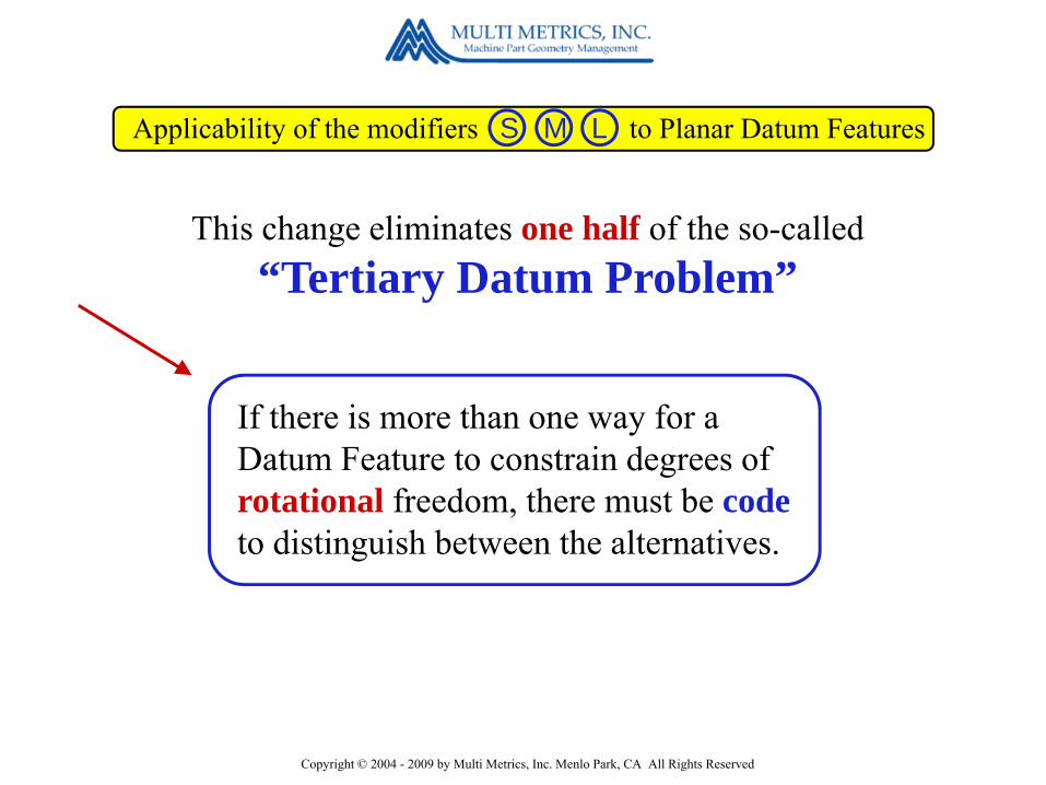
This change eliminates one half of the so-called“Tertiary Datum Problem”
Applicability of the modifiers S M L to Planar Datum Features
If there is more than one way for a Datum Feature to constrain degrees of rotational freedom, there must be codeto distinguish between the alternatives.

Copyright © 2004 - 2009 by Multi Metrics, Inc. Menlo Park, CA All Rights Reserved
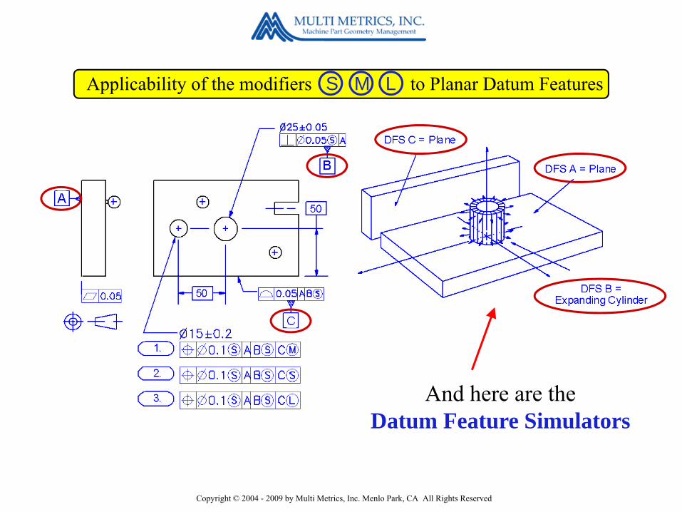
Here’s the part drawing !
Applicability of the modifiers S M L to Planar Datum Features
Examples
Copyright © 2004 - 2009 by Multi Metrics, Inc. Menlo Park, CA All Rights Reserved
Applicability of the modifiers S M L to Planar Datum Features
And here are theDatum Feature Simulators
Copyright © 2004 - 2009 by Multi Metrics, Inc. Menlo Park, CA All Rights Reserved
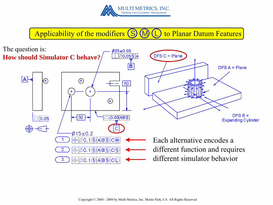
Applicability of the modifiers S M L to Planar Datum Features
Each alternative encodes a different function and requires different simulator behavior
The question is:How should Simulator C behave?

Copyright © 2004 - 2009 by Multi Metrics, Inc. Menlo Park, CA All Rights Reserved
Simulator “C”
Applicability of the modifiers S M L to Planar Datum Features
First . . . the details for M :
Simulator fixedIn-
Space
M fixes Simulator C at the Virtual Maximum Material BoundaryPermitting residual in-space roll M obility !

Copyright © 2004 - 2009 by Multi Metrics, Inc. Menlo Park, CA All Rights Reserved
S requires Simulator C to slide up to and consume all the space outside Datum Feature C, imposing
Next . . . the details for S :
Simulator Sliding
Simulator “C”
Applicability of the modifiers S M L to Planar Datum Features
in-space roll S tability !

Copyright © 2004 - 2009 by Multi Metrics, Inc. Menlo Park, CA All Rights Reserved
L fixes Simulator C at the Virtual Least Material BoundaryPermitting residual
And here . . . the details for L :
DFS “C”
Applicability of the modifiers S M L to Planar Datum Features
in-material roll L ability !
Simulator fixedIn-
Material

Copyright © 2004 - 2009 by Multi Metrics, Inc. Menlo Park, CA All Rights Reserved
Applicability of the modifiers S M L to Planar Datum Features
Simulator C is fixed in-space !
If the planar surface is referenced at M
in-space roll M obility !
Review
Copyright © 2004 - 2009 by Multi Metrics, Inc. Menlo Park, CA All Rights Reserved
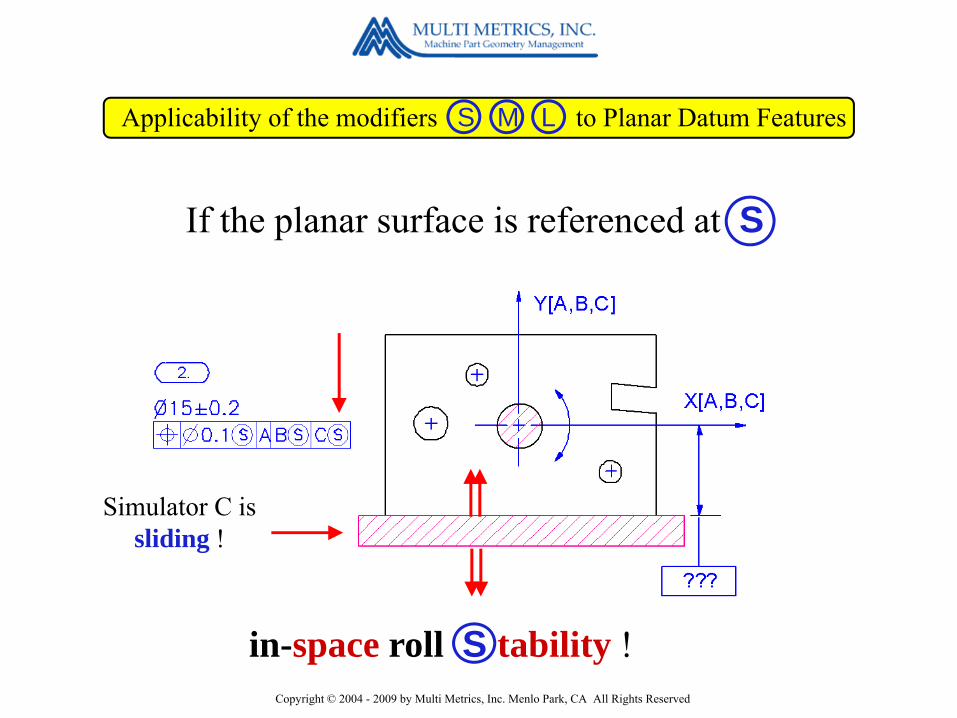
Applicability of the modifiers S M L to Planar Datum Features
Simulator C is sliding !
If the planar surface is referenced at S
in-space roll S tability !

Copyright © 2004 - 2009 by Multi Metrics, Inc. Menlo Park, CA All Rights Reserved
Applicability of the modifiers S M L to Planar Datum Features
Simulator C is fixed in-material !
If the planar surface is referenced at L
in-material roll L ability !

Copyright © 2004 - 2009 by Multi Metrics, Inc. Menlo Park, CA All Rights Reserved
How useful is this addition?
Applicability of the modifiers S M L to Planar Datum Features
Veryencodes potential “mobility” (or play) between mating planar features during assembly, and permits taking advantage of it.
encodes “stability” between mating planar features during assembly, and forbids taking advantage of potential “play”.
encodes potential “looseness” between a planar Datum Feature in its cast versus its machined condition, and permits taking advantage of it during material removal.
M
S
L

Copyright © 2004 - 2009 by Multi Metrics, Inc. Menlo Park, CA All Rights Reserved
Y14.5 2009 Changes and their Impact
New Tools impacting Datums1. A more complete definition of Datums2. Applicability of the modifiers S M L to Planar Datum Features3. The new Datum (Feature Simulator) Translation Modifier: ►4. New Degrees of Constraint Modifiers: [u,v,w,x,y,z]5. Expanded Composite Feature Control Frames – Up to four tiers.6. New Datum Reference Frame Axis Labels: X[A,B,C], Y[…] etc.

Copyright © 2004 - 2009 by Multi Metrics, Inc. Menlo Park, CA All Rights Reserved
Datum (Feature Simulator) Translation Modifier: ►
Applicability
The translation modifier applies only to “Datum Features of Size”.
Whereas S M and L require Datum Feature Simulators to expand, contract or be fixed in size, addition of the translation modifier frees Datum Feature Simulators of size to also translate during the DRF establishment process.

Copyright © 2004 - 2009 by Multi Metrics, Inc. Menlo Park, CA All Rights Reserved
Datum (Feature Simulator) Translation Modifier: ►
If there is more than one way for a Datum Feature to constrain degrees of rotational freedom, there must be codeto distinguish between the alternatives.
The translation modifier eliminates theother half of the so-called
“Tertiary Datum Problem”

Copyright © 2004 - 2009 by Multi Metrics, Inc. Menlo Park, CA All Rights Reserved
Datum (Feature Simulator) Translation Modifier: ►
Here’s one possible application of the Translation modifier.
Here’s a part drawing !
Examples

Copyright © 2004 - 2009 by Multi Metrics, Inc. Menlo Park, CA All Rights Reserved
Datum (Feature Simulator) Translation Modifier: ►
Here are theDatum Feature Simulators

Copyright © 2004 - 2009 by Multi Metrics, Inc. Menlo Park, CA All Rights Reserved
Datum (Feature Simulator) Translation Modifier: ►
In this case Datum Feature C serves as a clocking Datum Feature !
And here are the details for M without
M requires Datum Feature Simulator C to be fixed in size and location, leading to potential roll mobility based on Datum Feature C’s location.
Copyright © 2004 - 2009 by Multi Metrics, Inc. Menlo Park, CA All Rights Reserved
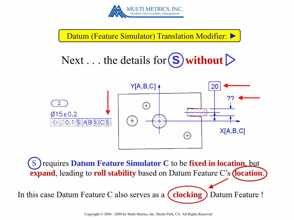
Datum (Feature Simulator) Translation Modifier: ►
In this case Datum Feature C also serves as a clocking Datum Feature !
Next . . . the details for S without
S requires Datum Feature Simulator C to be fixed in location, but expand, leading to roll stability based on Datum Feature C’s location.
Copyright © 2004 - 2009 by Multi Metrics, Inc. Menlo Park, CA All Rights Reserved
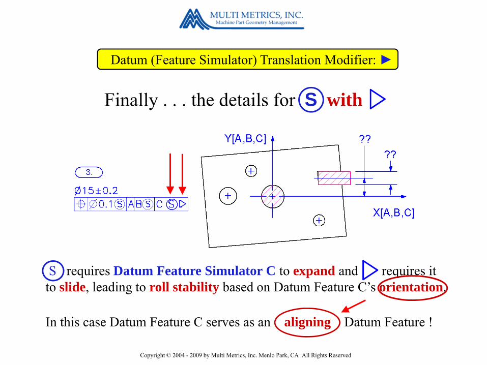
Datum (Feature Simulator) Translation Modifier: ►
In this case Datum Feature C serves as an aligning Datum Feature !
Finally . . . the details for S with
S requires Datum Feature Simulator C to expand and requires it to slide, leading to roll stability based on Datum Feature C’s orientation.

Copyright © 2004 - 2009 by Multi Metrics, Inc. Menlo Park, CA All Rights Reserved
Datum (Feature Simulator) Translation Modifier: ►
The simulator is fixed in location and fixed in size.
If M is used without
Clocking with residual roll M obility
Copyright © 2004 - 2009 by Multi Metrics, Inc. Menlo Park, CA All Rights Reserved
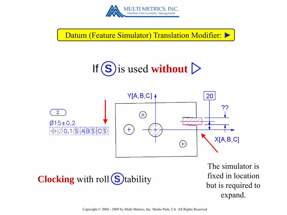
Datum (Feature Simulator) Translation Modifier: ►
The simulator is fixed in location but is required to
expand.
If S is used without
Clocking with roll S tability

Copyright © 2004 - 2009 by Multi Metrics, Inc. Menlo Park, CA All Rights Reserved
Datum (Feature Simulator) Translation Modifier: ►
The simulator is required to
expand and slide.
If S is used with
Aligning with roll S tability

Copyright © 2004 - 2009 by Multi Metrics, Inc. Menlo Park, CA All Rights Reserved
M +
encodes the “stability” and “aligning” function of roll constraining datum features of size during assembly.
encodes the potential “lability” (looseness) and also the “clocking” function of roll constraining, cast, forged or molded datum features during secondary machining operations.
encodes the potential “mobility” and also the “clocking” function of roll constraining datum features of size during assembly.
S +
L +
Datum (Feature Simulator) Translation Modifier: ►
Impact

Copyright © 2004 - 2009 by Multi Metrics, Inc. Menlo Park, CA All Rights Reserved
Quite
Datum (Feature Simulator) Translation Modifier: ►
How useful is the Translation modifier ?
Because, even though it will be rarely required, it enables explicit feature
function encoding.

Copyright © 2004 - 2009 by Multi Metrics, Inc. Menlo Park, CA All Rights Reserved
Y14.5 2009 Changes and their Impact
New Tools impacting Datums1. A more complete definition of Datums2. Applicability of the modifiers S M L to Planar Datum Features3. The new Datum (Feature Simulator) Translation Modifier: ►4. New Degrees of Constraint Modifiers: [u,v,w,x,y,z]5. Expanded Composite Feature Control Frames – Up to four tiers.6. New Datum Reference Frame Axis Labels: X[A,B,C], Y[…] etc.

Copyright © 2004 - 2009 by Multi Metrics, Inc. Menlo Park, CA All Rights Reserved
Degrees of Constraint Modifiers: [u,v,w,x,y,z]
What’s the purpose of Datum Features ?
To constrainrotational and translational
degrees of freedomduring assembly processes!
Let’s start with a question:

Copyright © 2004 - 2009 by Multi Metrics, Inc. Menlo Park, CA All Rights Reserved
Degrees of Constraint Modifiers: [u,v,w,x,y,z]
There are 6 degrees ofrotational and translational freedom:
3 Rotational:
and a set of six new tools for constraining them:
[u,v,w,x,y,z]
1. Tx2. Ty3. Tz
uvw
xyz
1. Pitch2. Yaw3. Roll
3 Translational:
The Degrees of Constraint Modifiers

Copyright © 2004 - 2009 by Multi Metrics, Inc. Menlo Park, CA All Rights Reserved
Degrees of Constraint Modifiers: [u,v,w,x,y,z]
Degrees of Constraint modifiers are placed inside brackets to the right of the Material Boundary modifier associated with a Datum Feature label, and serve to specify the degrees of freedom that a particular Datum Feature is required and permitted to constrain !
Degrees of Constraint modifiers make theCan, May, Must rule explicit !

Copyright © 2004 - 2009 by Multi Metrics, Inc. Menlo Park, CA All Rights Reserved
Degrees of Constraint Modifiers: [u,v,w,x,y,z]
Example:
All we have to do is list them in the Feature Control Frame
five Datum Features.
Just for fun, let’s try to control the left hand bore relative to a Datum Reference Frame established using . . .

Copyright © 2004 - 2009 by Multi Metrics, Inc. Menlo Park, CA All Rights Reserved
Degrees of Constraint Modifiers: [u,v,w,x,y,z]
But this doesn’t work, because A, B and C already constrain all six degrees of freedom !
Example:

Copyright © 2004 - 2009 by Multi Metrics, Inc. Menlo Park, CA All Rights Reserved
Degrees of Constraint Modifiers: [u,v,w,x,y,z]
Example:
UsingDegrees of Constraint
modifiers !
However, if this is a real, functional objective, which it could be, how can we encode it?

Copyright © 2004 - 2009 by Multi Metrics, Inc. Menlo Park, CA All Rights Reserved
Degrees of Constraint Modifiers: [u,v,w,x,y,z]
Example:Let’s use -1. A to constrain only pitch
and yaw.2. B to constrain only roll.3. C to constrain only
translation in Z4. D to constrain only
translation in X.5. E to constrain only
translation in Y.

Copyright © 2004 - 2009 by Multi Metrics, Inc. Menlo Park, CA All Rights Reserved
Degrees of Constraint Modifiers: [u,v,w,x,y,z]
And here it is !The
Datum Reference Framedefined by our fiveDatum Features !
Copyright © 2004 - 2009 by Multi Metrics, Inc. Menlo Park, CA All Rights Reserved
Degrees of Constraint Modifiers: [u,v,w,x,y,z]
But first, the 2009 change in
Composite Feature Control Frames
Now we need a much morepractical
Degrees of Constraint Modifiers
example.

Copyright © 2004 - 2009 by Multi Metrics, Inc. Menlo Park, CA All Rights Reserved
Y14.5 2009 Changes and their Impact
New Tools impacting Datums1. A more complete definition of Datums2. Applicability of the modifiers S M L to Planar Datum Features3. The new Datum (Feature Simulator) Translation Modifier: ►4. New Degrees of Constraint Modifiers: [u,v,w,x,y,z]5. Expanded Composite Feature Control Frames – Up to four tiers.6. New Datum Reference Frame Axis Labels: X[A,B,C], Y[…] etc.

Copyright © 2004 - 2009 by Multi Metrics, Inc. Menlo Park, CA All Rights Reserved
Composite Feature Control Frames – Up to four tiers
Composite Feature Control Frames ?But, what’s so special about
They provide specialfunction encoding power.
Composite Feature Control Frames can now have up to four tiers !!!

Copyright © 2004 - 2009 by Multi Metrics, Inc. Menlo Park, CA All Rights Reserved
Composite Feature Control Frames – Up to four tiers
by limiting the Datum Features in the second and all lower tiers to constraining only rotational degrees of freedom !
How?
Copyright © 2004 - 2009 by Multi Metrics, Inc. Menlo Park, CA All Rights Reserved
Composite Feature Control Frames – Up to four tiers
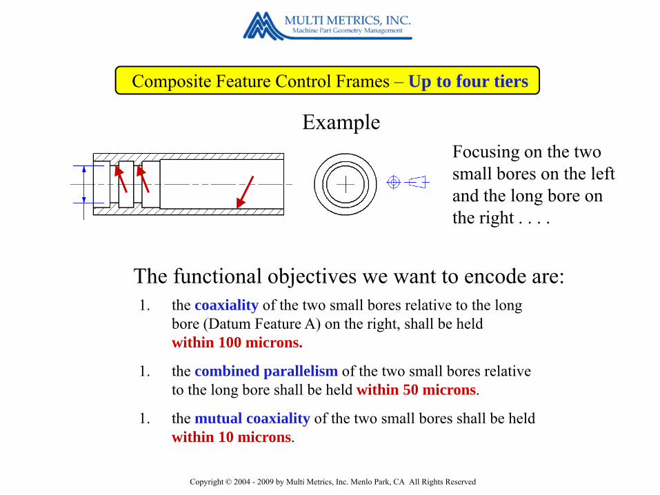
The functional objectives we want to encode are:1. the coaxiality of the two small bores relative to the long
bore (Datum Feature A) on the right, shall be heldwithin 100 microns.
1. the combined parallelism of the two small bores relative to the long bore shall be held within 50 microns.
1. the mutual coaxiality of the two small bores shall be held within 10 microns.
Focusing on the two small bores on the left and the long bore on the right . . . .
Example

Copyright © 2004 - 2009 by Multi Metrics, Inc. Menlo Park, CA All Rights Reserved
Composite Feature Control Frames – Up to four tiers
1. Because A in the first tier constrains pitch, yaw and both degrees oftranslational freedom, the first tier imposes global coaxiality relative to A.
Here’s how we can do that using a Composite Feature Control Frame!
Copyright © 2004 - 2009 by Multi Metrics, Inc. Menlo Park, CA All Rights Reserved
Composite Feature Control Frames – Up to four tiers
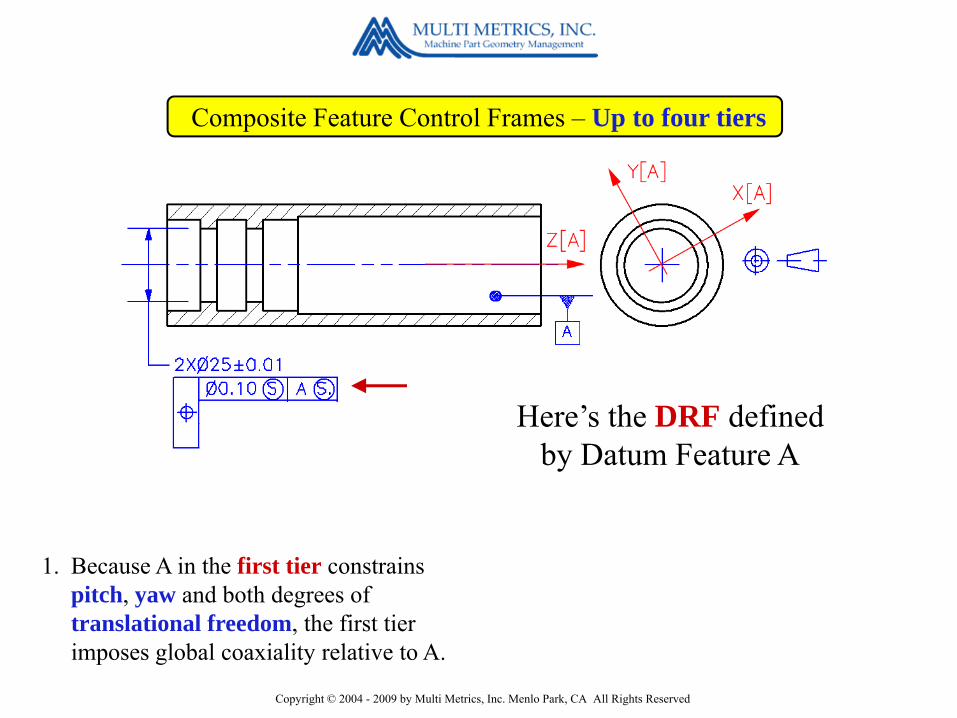
1. Because A in the first tier constrains pitch, yaw and both degrees oftranslational freedom, the first tier imposes global coaxiality relative to A.
Here’s the DRF defined by Datum Feature A

Copyright © 2004 - 2009 by Multi Metrics, Inc. Menlo Park, CA All Rights Reserved
Composite Feature Control Frames – Up to four tiers
First Tier Tolerance Zone Ø0.10
1. Because A in the first tier constrains pitch, yaw and both degrees oftranslational freedom, the first tier imposes global coaxiality relative to A.
. . . and here is the location constrained, cylindrical Position tolerance zone of diameter 100 microns.
Copyright © 2004 - 2009 by Multi Metrics, Inc. Menlo Park, CA All Rights Reserved
Composite Feature Control Frames – Up to four tiers
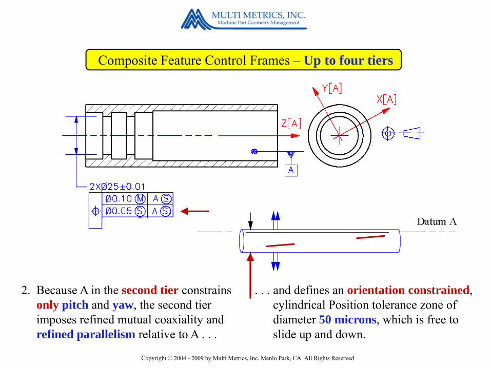
2. Because A in the second tier constrains only pitch and yaw, the second tier imposes refined mutual coaxiality and refined parallelism relative to A . . .
. . . and defines an orientation constrained, cylindrical Position tolerance zone of diameter 50 microns, which is free to slide up and down.
Copyright © 2004 - 2009 by Multi Metrics, Inc. Menlo Park, CA All Rights Reserved
Composite Feature Control Frames – Up to four tiers
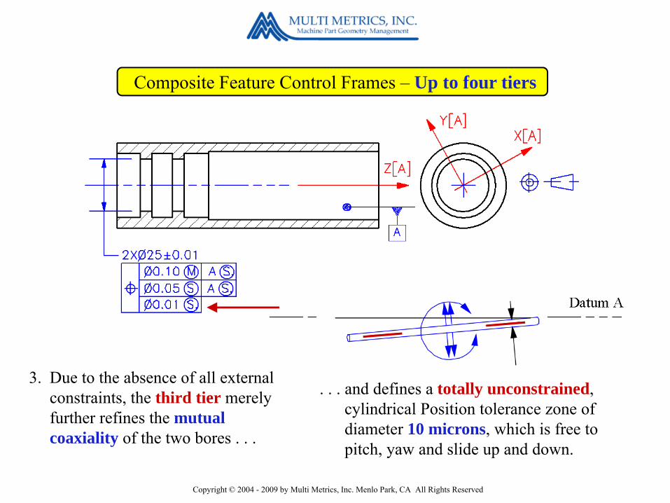
3. Due to the absence of all external constraints, the third tier merely further refines the mutual coaxiality of the two bores . . .
. . . and defines a totally unconstrained, cylindrical Position tolerance zone of diameter 10 microns, which is free to pitch, yaw and slide up and down.

Copyright © 2004 - 2009 by Multi Metrics, Inc. Menlo Park, CA All Rights Reserved
Composite Feature Control Frames – Up to four tiers
Third Tier Tolerance Zone Ø0.01
First Tier Tolerance Zone Ø0.10
Second Tier Tolerance Zone Ø0.05Here are all three tolerance zones
stacked together !
Copyright © 2004 - 2009 by Multi Metrics, Inc. Menlo Park, CA All Rights Reserved
Composite Feature Control Frames – Up to four tiers
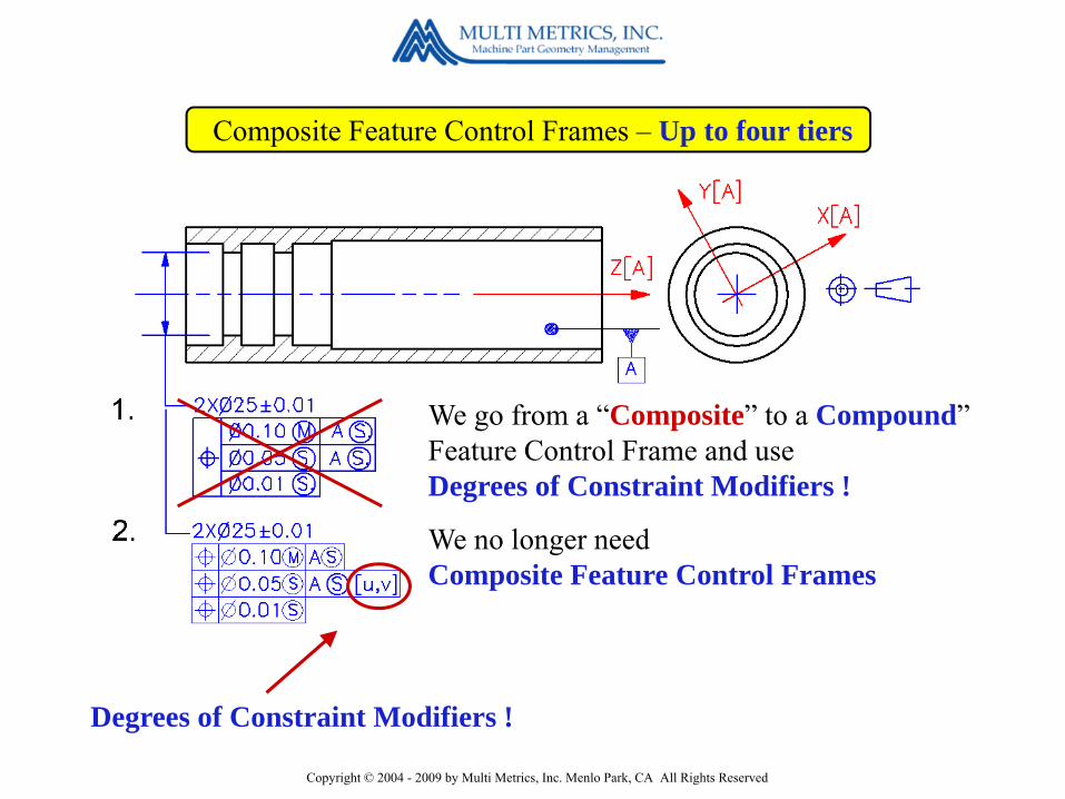
We no longer needComposite Feature Control Frames
Degrees of Constraint Modifiers !
We go from a “Composite” to a Compound”Feature Control Frame and use Degrees of Constraint Modifiers !
Copyright © 2004 - 2009 by Multi Metrics, Inc. Menlo Park, CA All Rights Reserved
Composite Feature Control Frames – Up to four tiers
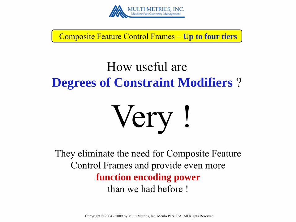
How useful areDegrees of Constraint Modifiers ?
Very !They eliminate the need for Composite Feature
Control Frames and provide even more function encoding power
than we had before !
Copyright © 2004 - 2009 by Multi Metrics, Inc. Menlo Park, CA All Rights Reserved
Y14.5 2009 Changes and their Impact
New Tools impacting Datums1. A more complete definition of Datums2. Applicability of the modifiers S M L to Planar Datum Features3. The new Datum (Feature Simulator) Translation Modifier: ►4. New Degrees of Constraint Modifiers: [u,v,w,x,y,z]5. Expanded Composite Feature Control Frames – Up to four tiers.6. New Datum Reference Frame Axis Labels: X[A,B,C], Y[…] etc.

Copyright © 2004 - 2009 by Multi Metrics, Inc. Menlo Park, CA All Rights Reserved
Datum Reference Frame Axis Labels: X[A,B,C], Y[…] etc.
As we have already seen,
locating the axes of a Datum Reference Frame isn’t so easy !
Let’s do an exercise.

Copyright © 2004 - 2009 by Multi Metrics, Inc. Menlo Park, CA All Rights Reserved
Datum Reference Frame Axis Labels: X[A,B,C], Y[…] etc.
Datum Feature A constrains pitch, yaw and one degree of translational freedom.
Can you figure out the locations of the X, Y and Z axes of the DRF defined here?
Datum Feature B constrains roll and one more degree of translational freedom.
Datum Feature C constrains thelast degree of translational freedom.

Copyright © 2004 - 2009 by Multi Metrics, Inc. Menlo Park, CA All Rights Reserved
Datum Reference Frame Axis Labels: X[A,B,C], Y[…] etc.
Here they are !Can you figure out the locations of the X, Y and Z axes of the DRF defined here?
Copyright © 2004 - 2009 by Multi Metrics, Inc. Menlo Park, CA All Rights Reserved
Datum Reference Frame Axis Labels: X[A,B,C], Y[…] etc.
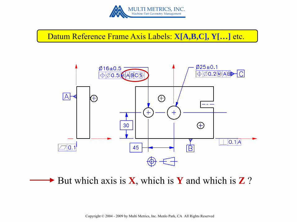
But which axis is X, which is Y and which is Z ?

Copyright © 2004 - 2009 by Multi Metrics, Inc. Menlo Park, CA All Rights Reserved
Datum Reference Frame Axis Labels
We now have
Datum Reference Frame Axis Labels: X[A,B,C], Y[…] etc.
X[A,B,C]Y[A,B,C]Z[A,B,C]

Copyright © 2004 - 2009 by Multi Metrics, Inc. Menlo Park, CA All Rights Reserved
Datum Reference Frame Axis Labels: X[A,B,C], Y[…] etc.
so everyone knows exactly what’s going on !

Copyright © 2004 - 2009 by Multi Metrics, Inc. Menlo Park, CA All Rights Reserved
1) DRF axis labels accelerate the decoding of Feature Control Frames in the machine shop and in inspection.
2) DRF axis labels standardize coordinate measuring machine data reporting.
3) DRF axis labels are required when using Degrees of Constraint modifiers, because the axes are referenced in the code.
Benefits
Datum Reference Frame Axis Labels: X[A,B,C], Y[…] etc.

Copyright © 2004 - 2009 by Multi Metrics, Inc. Menlo Park, CA All Rights Reserved
Y14.5 2009 Changes and their Impact
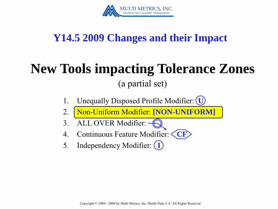
1. Unequally Disposed Profile Modifier: U2. Non-Uniform Modifier: [NON-UNIFORM]3. ALL OVER Modifier: 4. Continuous Feature Modifier: CF5. Independency Modifier: I
New Tools impacting Tolerance Zones(a partial set)

Copyright © 2004 - 2009 by Multi Metrics, Inc. Menlo Park, CA All Rights Reserved
The Surface Profile tool specifies symmetrical skin-like tolerance zones by default.
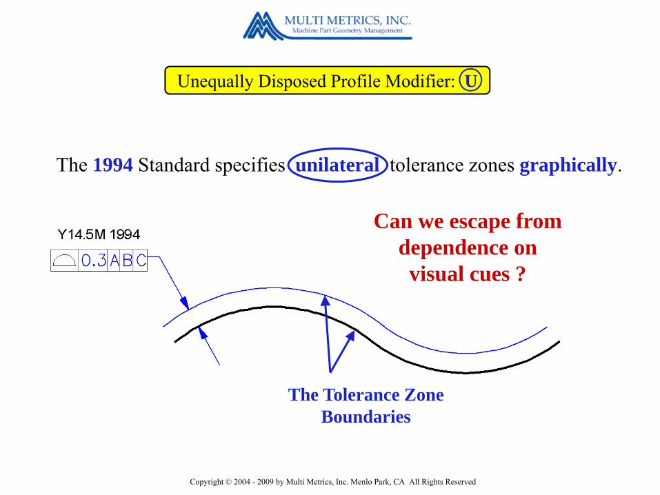
Unequally Disposed Profile Modifier: U
The Tolerance Zone
Copyright © 2004 - 2009 by Multi Metrics, Inc. Menlo Park, CA All Rights Reserved
Unequally Disposed Profile Modifier: U
Can we escape from dependence on visual cues ?
The Tolerance Zone Boundaries
The 1994 Standard specifies unilateral tolerance zones graphically.

Copyright © 2004 - 2009 by Multi Metrics, Inc. Menlo Park, CA All Rights Reserved
Unequally Disposed Profile Modifier: U
How does it work?
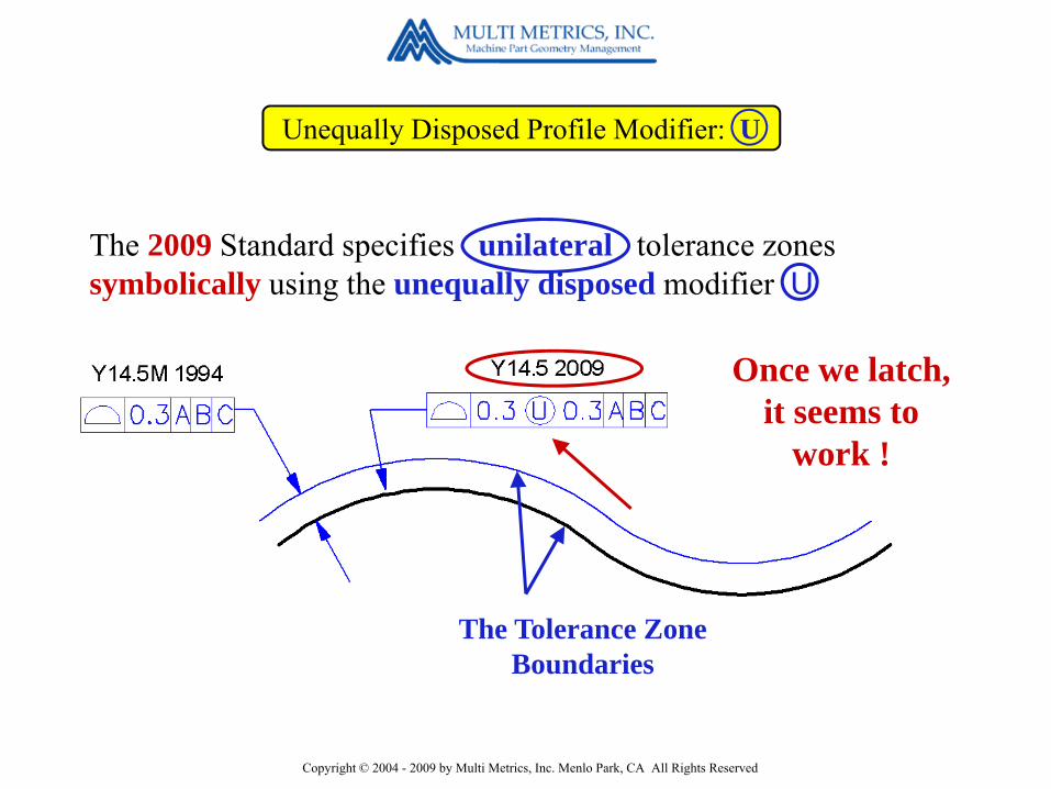
The 2009 Standard specifies unilateral tolerance zones symbolically using the unequally disposed modifier U
Copyright © 2004 - 2009 by Multi Metrics, Inc. Menlo Park, CA All Rights Reserved
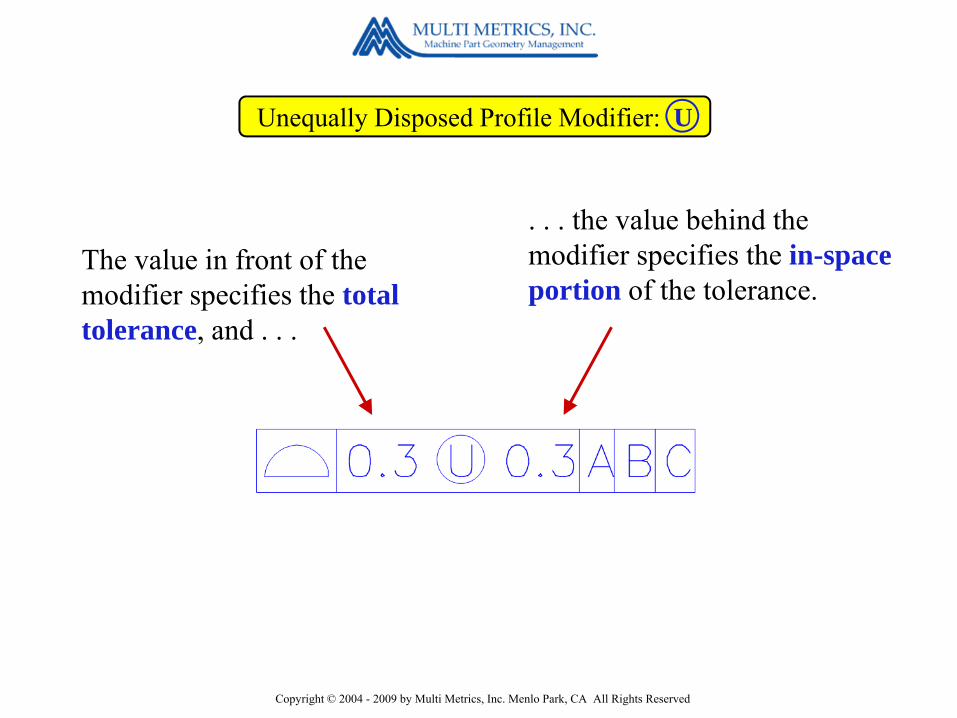
The value in front of the modifier specifies the total tolerance, and . . .
Unequally Disposed Profile Modifier: U
. . . the value behind the modifier specifies the in-space portion of the tolerance.
Copyright © 2004 - 2009 by Multi Metrics, Inc. Menlo Park, CA All Rights Reserved
Unequally Disposed Profile Modifier: U
Once we latch, it seems to
work !
The Tolerance Zone Boundaries
The 2009 Standard specifies unilateral tolerance zones symbolically using the unequally disposed modifier U

Copyright © 2004 - 2009 by Multi Metrics, Inc. Menlo Park, CA All Rights Reserved
Unequally Disposed Profile Modifier: U
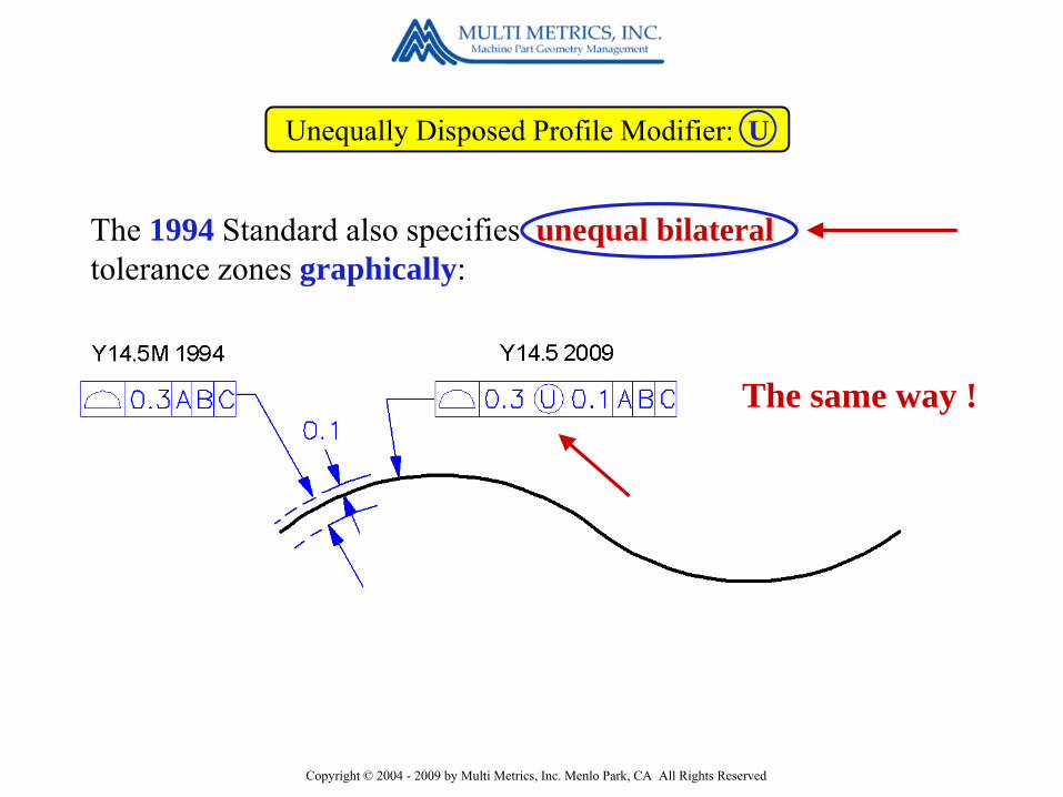
The 1994 Standard also specifies unequal bilateraltolerance zones graphically:
How does 2009 handle this ?
Copyright © 2004 - 2009 by Multi Metrics, Inc. Menlo Park, CA All Rights Reserved
Unequally Disposed Profile Modifier: U
The 1994 Standard also specifies unequal bilateraltolerance zones graphically:
The same way !

Copyright © 2004 - 2009 by Multi Metrics, Inc. Menlo Park, CA All Rights Reserved
The value in front of the modifier specifies the total tolerance, and . . .
Unequally Disposed Profile Modifier: U
. . . the value behind the modifier specifies the in-space portion of the tolerance.

Copyright © 2004 - 2009 by Multi Metrics, Inc. Menlo Park, CA All Rights Reserved
Unequally Disposed Profile Modifier: U
The Tolerance Zone Boundaries
The 2009 Standard also uses the symbol U to specify unequal bilateral tolerance zones

Copyright © 2004 - 2009 by Multi Metrics, Inc. Menlo Park, CA All Rights Reserved
Unequally Disposed Profile Modifier: U
We have eliminated dependence on visual cues !
How useful is theModifier U ?
Very !
Copyright © 2004 - 2009 by Multi Metrics, Inc. Menlo Park, CA All Rights Reserved
Y14.5 2009 Changes and their Impact
1. Unequally Disposed Profile Modifier: U2. Non-Uniform Modifier: [NON-UNIFORM]3. ALL OVER Modifier: 4. Continuous Feature Modifier: CF5. Independency Modifier: I
New Tools impacting Tolerance Zones(a partial set)

Copyright © 2004 - 2009 by Multi Metrics, Inc. Menlo Park, CA All Rights Reserved
Non-Uniform Modifier: [NON-UNIFORM]
How do we specify a Surface Profile Tolerance Zone whose thickness is required to vary ?
. . . Using a the non-uniform modifier plus . . .
. . . graphical indications of the boundaries embedded in the CAD model or added to the drawing.

Copyright © 2004 - 2009 by Multi Metrics, Inc. Menlo Park, CA All Rights Reserved
Y14.5 2009 Changes and their Impact
1. Unequally Disposed Profile Modifier: U2. Non-Uniform Modifier: [NON-UNIFORM]3. ALL OVER Modifier: 4. Continuous Feature Modifier: CF5. Independency Modifier: I
New Tools impacting Tolerance Zones(a partial set)

Copyright © 2004 - 2009 by Multi Metrics, Inc. Menlo Park, CA All Rights Reserved
ALL OVER Modifier:
The 2009 Standard provides a symbol as a replacement for the note ALL OVER.
But the note ALL OVER isstill permitted !

Copyright © 2004 - 2009 by Multi Metrics, Inc. Menlo Park, CA All Rights Reserved
Y14.5 2009 Changes and their Impact
1. Unequally Disposed Profile Modifier: U2. Non-Uniform Modifier: [NON-UNIFORM]3. ALL OVER Modifier: 4. Continuous Feature Modifier: CF5. Independency Modifier: I
New Tools impacting Tolerance Zones(a partial set)

Copyright © 2004 - 2009 by Multi Metrics, Inc. Menlo Park, CA All Rights Reserved
Continuous Feature Modifier: CF
When applied to an interrupted collection of Features of Size, the “Continuous Feature” modifier imposes the Envelope Rule on the entire set as a group.
Other applications of the Continuous Feature modifier are also possible, but are not mentioned in the 2009 Standard.

Copyright © 2004 - 2009 by Multi Metrics, Inc. Menlo Park, CA All Rights Reserved
Y14.5 2009 Changes and their Impact
1. Unequally Disposed Profile Modifier: U2. Non-Uniform Modifier: [NON-UNIFORM]3. ALL OVER Modifier: 4. Continuous Feature Modifier: CF5. Independency Modifier: I
New Tools impacting Tolerance Zones(a partial set)
Copyright © 2004 - 2009 by Multi Metrics, Inc. Menlo Park, CA All Rights Reserved
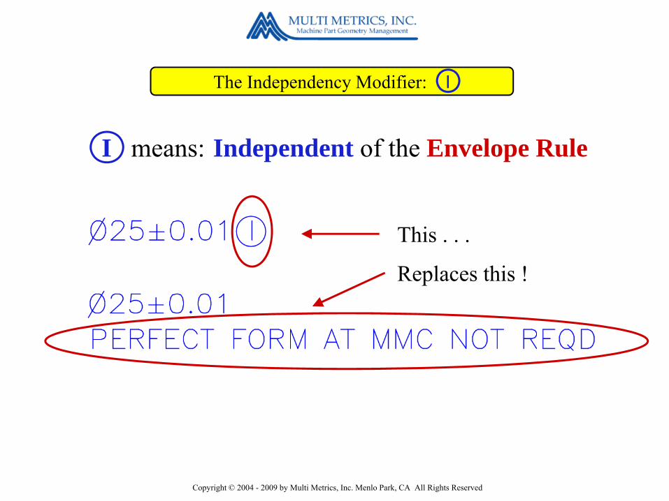
The Independency Modifier: I
This . . .
Replaces this !
I means: Independent of the Envelope Rule

Copyright © 2004 - 2009 by Multi Metrics, Inc. Menlo Park, CA All Rights Reserved
The Independency Modifier: I
No ! because the automatically imposed Envelope Rule requires global Cylindricity of 0.02 mm, which is impossible in such a long shaft.
ExampleIs this a functional specification?
Copyright © 2004 - 2009 by Multi Metrics, Inc. Menlo Park, CA All Rights Reserved
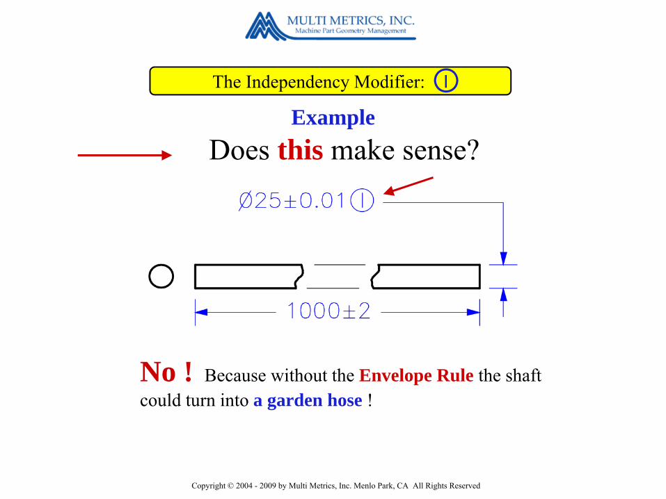
The Independency Modifier: I
No ! Because without the Envelope Rule the shaft could turn into a garden hose !
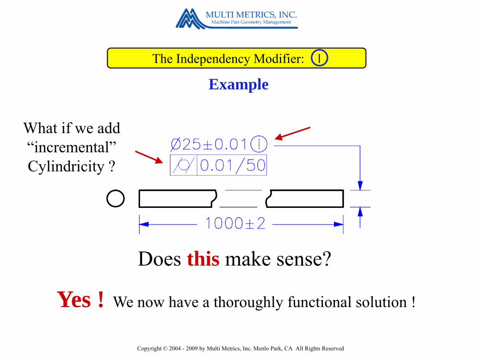
ExampleDoes this make sense?
Copyright © 2004 - 2009 by Multi Metrics, Inc. Menlo Park, CA All Rights Reserved
The Independency Modifier: I
Yes ! We now have a thoroughly functional solution !
Example
Does this make sense?
What if we add “incremental” Cylindricity ?

Copyright © 2004 - 2009 by Multi Metrics, Inc. Menlo Park, CA All Rights Reserved
Y14.5 2009 Changes and their Impact
Disappointments1. Still no clearly defined, accessible, sets of Rules.2. The Concentricity and Symmetry tools unchanged.3. The Radius and Controlled Radius Tools still define
non-functional crescent shaped tolerance zones.4. Still no tool for controlling the orientation and
location of curved “spines”.5. Still no page number references in the index.

Copyright © 2004 - 2009 by Multi Metrics, Inc. Menlo Park, CA All Rights Reserved
Multi Metrics, Inc.is the home of
SmartGD&T TM
Concluding Remarks

Copyright © 2004 - 2009 by Multi Metrics, Inc. Menlo Park, CA All Rights Reserved
What isSmartGD&T ?
Concluding Remarks
SmartGD&T is a rule-based, process driven approach to either the ASME Y14.5M 1994 or ISO 1101 standard, which makes it possible to “encode” and “decode”,rather than “interpret” GD&T, and get it right the first time.

Copyright © 2004 - 2009 by Multi Metrics, Inc. Menlo Park, CA All Rights Reserved
Founded in 1975, Multi Metrics provides the following
• SmartGD&T Technology Licensing• Corporate GD&T Implementation Planning• On-Site GD&T End–user and Trainer Training• On-Site & Remote GD&T “Encoding” & “Decoding”
Services
Services
• SmartGD&T Pseudo-Code• Training Manuals & Presentation Materials• Training Models• Reference Books
Products

Copyright © 2004 - 2009 by Multi Metrics, Inc. Menlo Park, CA All Rights Reserved
How can we help you ?

Copyright © 2004 - 2009 by Multi Metrics, Inc. Menlo Park, CA All Rights Reserved
Please visitwww.multimetrics.com
and give us a call at650-328-0200
Copyright © 2004 - 2009 by Multi Metrics, Inc. Menlo Park, CA All Rights Reserved
Thank you !Bob Connors
&The Carl Zeiss CMM User
Group !
Bill Tandler


