Embed Size (px)
Citation preview
OSNA-Pumpen GmbH Brückenstrasse 3 D - 49090 Osnabrück Telefon +49 541/1211-0 Telefax +49 541/1211-220 www.osna.de [email protected]
Assembling and Operating Instructions
Multi-Stage Centrifugal Pumps
MKH / MKE / MKV
in horizontal and vertical construction
1 GENERAL INSTRUCTION 4
1.1 Information on the operating instructions 4 1.2 Appropriate usage 4 1.3 Model code 4 1.4 Range of supply 5
2 SAFETY REGULATIONS 6 2.1 General information 6 2.2 Identification of advice 6 2.3 Qualification and training of the personnel 6 2.4 Danger by disregard of the safety regulations 6 2.5 Security-conscious working 7 2.6 Safety regulations for the operator 7 2.7 Safety regulations for maintenance, inspection, and assembly 7 2.8 Unauthorized alterations and spare part production 7 2.9 Inadmissible modes of operation 7
3 TRANSPORT AND INTERIM STORAGE 8 3.1 Transport 8 3.2 Interim storage 8
4 ASSEMBLY UND MODE OF OPERATION 9 4.1 Mode of operation 9 4.2 Function and operation elements 9 4.3 Operating data 9
5 INSTALLATION/MOUNTING 10 5.1 Installation 10
5.1.1 Motor assembly 11 5.2 Pipe lines 12
5.2.1 Dimensioning of the suction pipe 12 5.3 Electrical conncetion 13
6 STARTING/PUTTING OUT OF OPERATION 14 6.1 Starting 14
6.1.1 Shaft seals 14 6.1.2 Checking direction of rotation 15 6.1.3 Filling up 15 6.1.4 Starting the pump 15 6.1.5 Minimum capacities 15
6.2 Putting out of operation 16 6.2.1 Draining the pump and frost protection 16 6.2.2 Starting the pump again 16
2
7 ATTENDANCE/MAINTENANCE 17
7.1 Maintenance 17 7.1.1 Maintenance of electric motors 17
7.2 Maintenance and lubrication 17 7.2.1 Operating control 17 7.2.2 Lubrication 18 7.2.2.1 Grease lubrication 18 7.2.2.2 Grease quality/grease change 18 7.2.2.3 Oil lubrication 18 7.2.2.4 Oil quality 18 7.2.2.5 Oil change 18
8 FAULTS / REASONS / REMOAVAL 19/20/21 9 SERVICE, SPARE PARTS, ACCESSORIES 22
3
1 General instructions
1.1 Information on the operating instructions
Before start-up the operating instructions have to be read carefully because OSNA is not liable for any damages or failures resulting from the disregard of these operating instructions.
For the initial operation and for all maintenance work please pay special attention to chapter 2 “Safety Regulations”.
The symbols used in this documentation are explained in chapter 2. Only with the knowledge of these operating instructions can mistakes be avoided and trouble-free and safe operation be ensured. The operating instructions do not take into consideration the local safety regulations that the operator has to comply with. The nameplate on the pump indicates the type, size, and execution of the pump as well as all relevant data.
1.2 Appropriate usage
This aggregate must not be used above the limit given by the nameplate as to the capacity, speed, or other instructions in the manual. Preset values with regard to electronic connections as well as assembly and maintenance instructions must be strictly observed. The usage of the aggregate beyond the above-mentioned conditions will lead to overload which the pump will not withstand. Disregard of this warning may result in injuries to persons or damage to property.
Liquids: Clean cold water and the liquids specified in this sales contract. The water must not contain abrasive or long-fibrous substances that might
corrode the pump materials. For other media please ask for further particulars. The pump must not be operated without any liquid. Otherwise it will run dry and thus be damaged. It has to be ensured that the foot valve is always covered by water.
Any use not mentioned above is improper. OSNA is not liable for any damage caused by improper usage. The operator alone bears the risk.
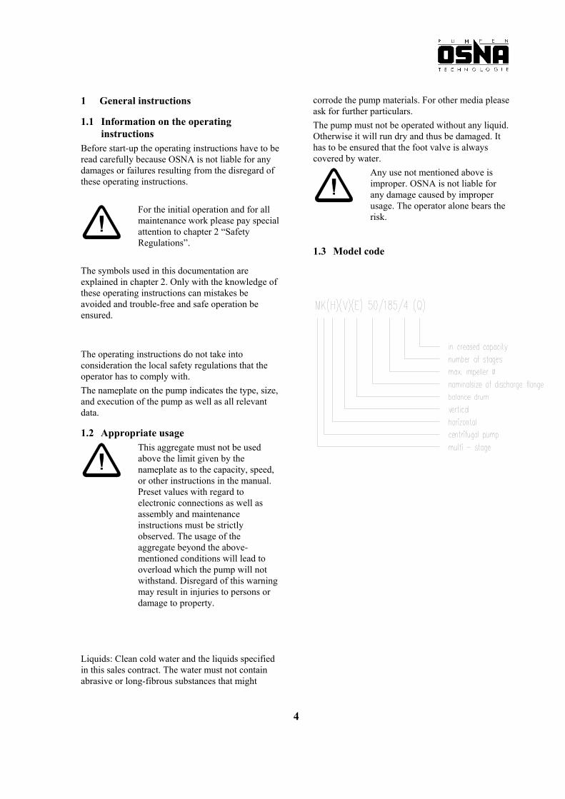
1.3 Model code
4
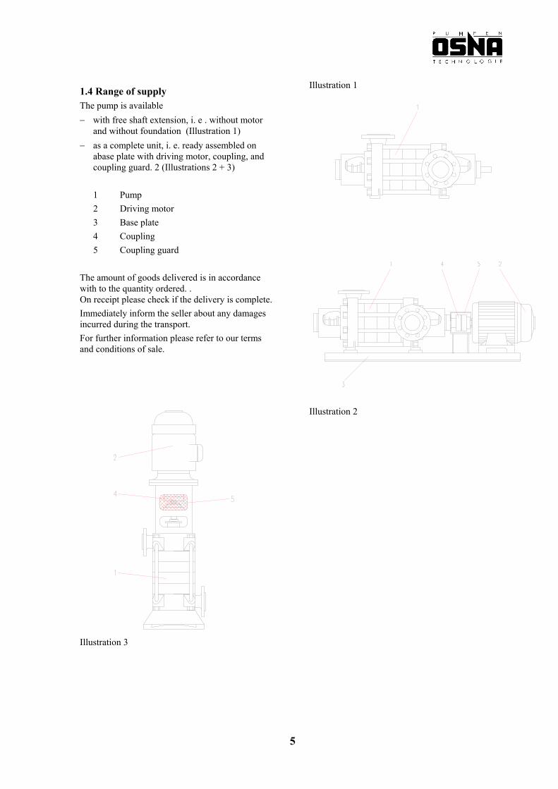
Illustration 1 1.4 Range of supply The pump is available − with free shaft extension, i. e . without motor
and without foundation (Illustration 1) − as a complete unit, i. e. ready assembled on
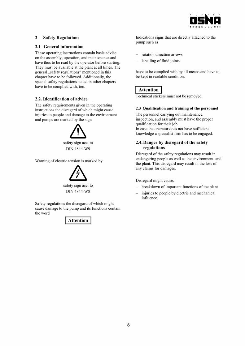
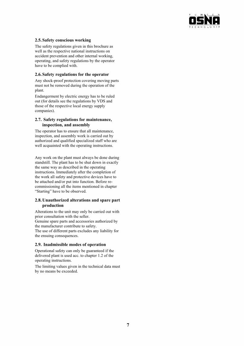
abase plate with driving motor, coupling, and coupling guard. 2 (Illustrations 2 + 3)
1 Pump 2 Driving motor 3 Base plate
4 Coupling 5 Coupling guard The amount of goods delivered is in accordance with to the quantity ordered. . On receipt please check if the delivery is complete. Immediately inform the seller about any damages incurred during the transport. For further information please refer to our terms and conditions of sale.
Illustration 2
Illustration 3
5
2 Safety Regulations Indications signs that are directly attached to the pump such as
2.1 General information These operating instructions contain basic advice on the assembly, operation, and maintenance and have thus to be read by the operator before starting. They must be available at the plant at all times. The general „safety regulations“ mentioned in this chapter have to be followed. Additionally, the special safety regulations stated in other chapters have to be complied with, too.
− rotation direction arrows − labelling of fluid joints
have to be complied with by all means and have to be kept in readable condition.
Attention Technical stickers must not be removed. 2.2. Identification of advice
The safety requirements given in the operating instructions the disregard of which might cause injuries to people and damage to the environment and pumps are marked by the sign
2.3 Qualification and training of the personnel The personnel carrying out maintenance, inspection, and assembly must have the proper qualification for their job. In case the operator does not have sufficient knowledge a specialist firm has to be engaged.
2.4. Danger by disregard of the safety
regulations safety sign acc. to
DIN 4844-W9 Disregard of the safety regulations may result in endangering people as well as the environment and the plant. This disregard may result in the loss of any claims for damages.
Warning of electric tension is marked by
Disregard might cause:
safety sign acc. to − breakdown of important functions of the plant DIN 4844-W8 − injuries to people by electric and mechanical
influence. Safety regulations the disregard of which might cause damage to the pump and its functions contain the word
Attention
6
2.5. Safety conscious working The safety regulations given in this brochure as well as the respective national instructions on accident prevention and other internal working, operating, and safety regulations by the operator have to be complied with.
2.6. Safety regulations for the operator Any shock-proof protection covering moving parts must not be removed during the operation of the plant. Endangerment by electric energy has to be ruled out (for details see the regulations by VDS and those of the respective local energy supply companies).
2.7. Safety regulations for maintenance, inspection, and assembly
The operator has to ensure that all maintenance, inspection, and assembly work is carried out by authorized and qualified specialized staff who are well acquainted with the operating instructions. Any work on the plant must always be done during standstill. The plant has to be shut down in exactly the same way as described in the operating instructions. Immediately after the completion of the work all safety and protective devices have to be attached and/or put into function. Before re-commissioning all the items mentioned in chapter “Starting” have to be observed.
2.8. Unauthorized alterations and spare part production
Alterations to the unit may only be carried out with prior consultation with the seller. Genuine spare parts and accessories authorized by the manufacturer contribute to safety. The use of different parts excludes any liability for the ensuing consequences.
2.9. Inadmissible modes of operation Operational safety can only be guaranteed if the delivered plant is used acc. to chapter 1.2 of the operating instructions. The limiting values given in the technical data must by no means be exceeded.
7
3. Transport and Interim Storage
3.1. Transport
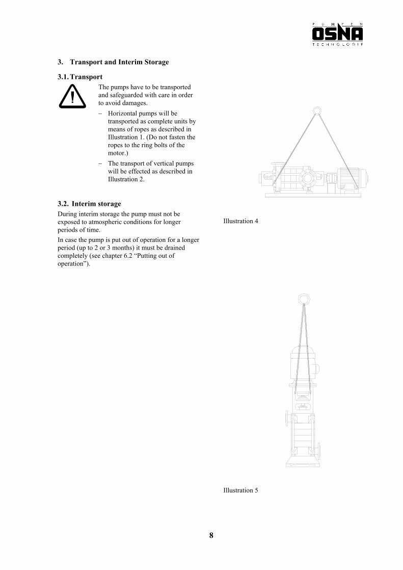
The pumps have to be transported and safeguarded with care in order to avoid damages. − Horizontal pumps will be
transported as complete units by means of ropes as described in Illustration 1. (Do not fasten the ropes to the ring bolts of the motor.)
− The transport of vertical pumps will be effected as described in Illustration 2.
3.2. Interim storage During interim storage the pump must not be
exposed to atmospheric conditions for longer periods of time.
Illustration 4
In case the pump is put out of operation for a longer period (up to 2 or 3 months) it must be drained completely (see chapter 6.2 “Putting out of operation”).
Illustration 5
8
4. Assembly and Mode of Operation
4.1. Mode of operation The pumps of series MKH / MKE / MKV are non-selfpriming, multistage high pressure centrifugal pumps in horizontal and vertical design that have proved their worth by smooth running and long operating life.
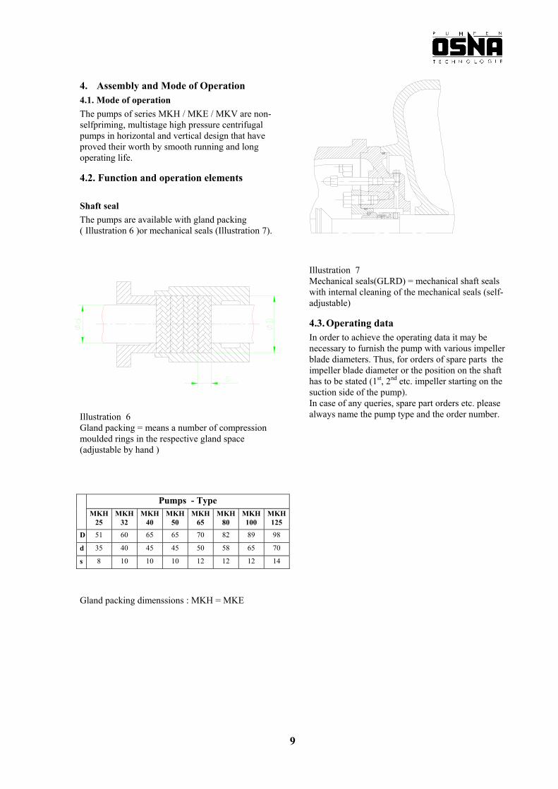
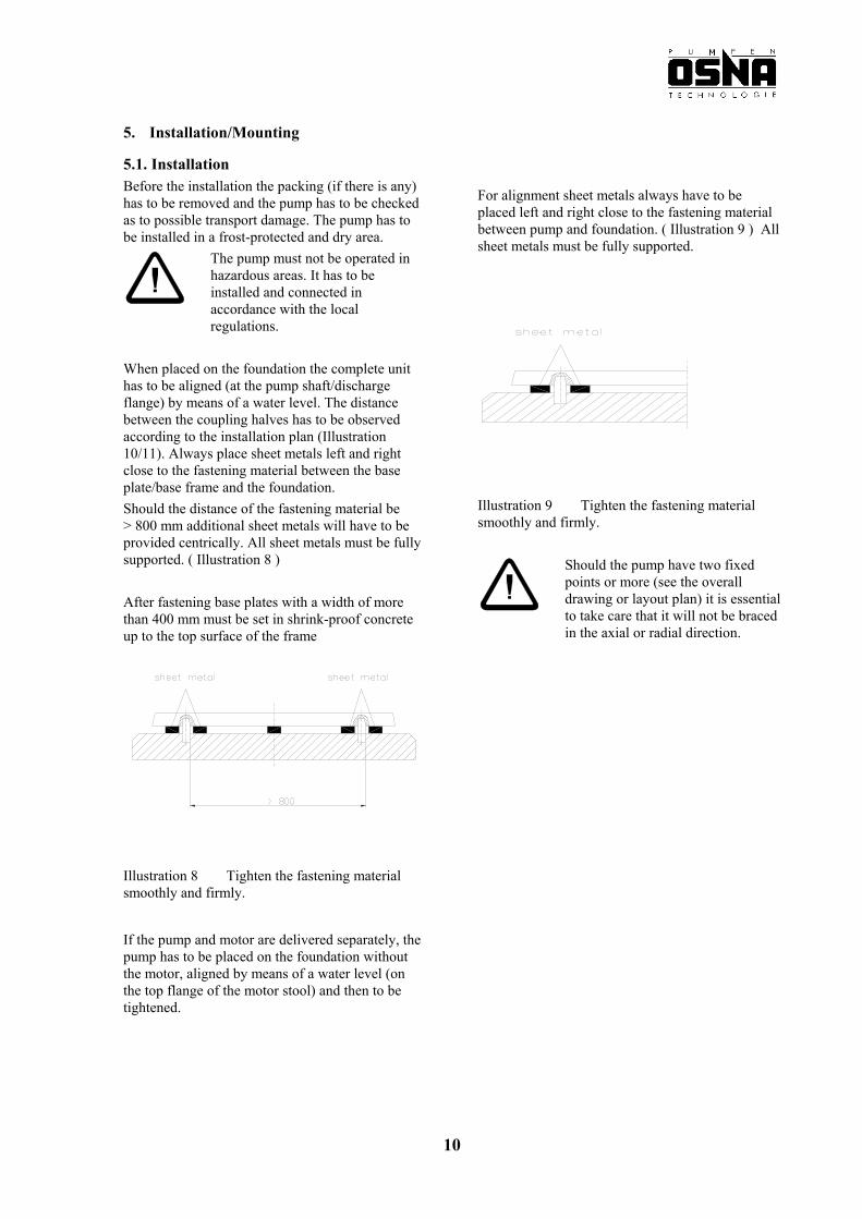
4.2. Function and operation elements Shaft seal The pumps are available with gland packing ( Illustration 6 )or mechanical seals (Illustration 7).
Illustration 7 Mechanical seals(GLRD) = mechanical shaft seals with internal cleaning of the mechanical seals (self-adjustable)
4.3. Operating data In order to achieve the operating data it may be necessary to furnish the pump with various impeller blade diameters. Thus, for orders of spare parts the impeller blade diameter or the position on the shaft has to be stated (1st, 2nd etc. impeller starting on the suction side of the pump). In case of any queries, spare part orders etc. please always name the pump type and the order number. Illustration 6
Gland packing = means a number of compression moulded rings in the respective gland space (adjustable by hand )
Pumps - Type MKH
25 MKH
32 MKH
40 MKH
50 MKH
65 MKH
80 MKH 100
MKH 125
D 51 60 65 65 70 82 89 98
d 35 40 45 45 50 58 65 70
s 8 10 10 10 12 12 12 14
Gland packing dimenssions : MKH = MKE
9
5. Installation/Mounting
5.1. Installation Before the installation the packing (if there is any) has to be removed and the pump has to be checked as to possible transport damage. The pump has to be installed in a frost-protected and dry area.
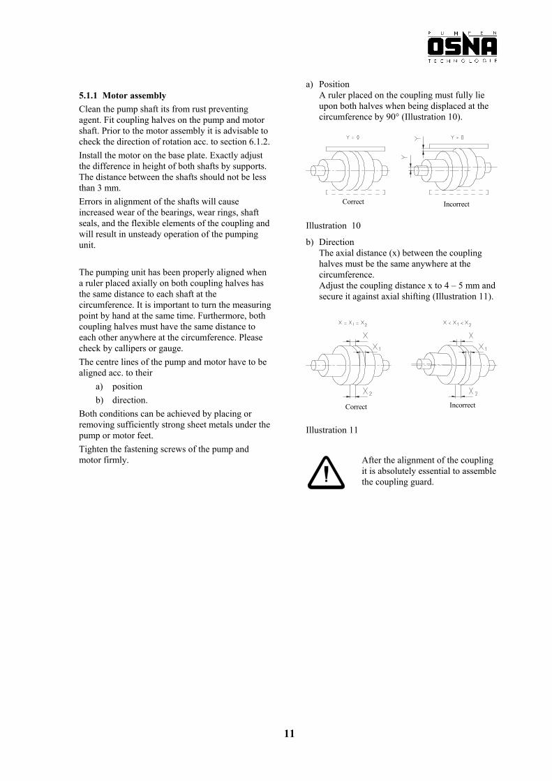
For alignment sheet metals always have to be placed left and right close to the fastening material between pump and foundation. ( Illustration 9 ) All sheet metals must be fully supported.
The pump must not be operated in hazardous areas. It has to be installed and connected in accordance with the local regulations.
When placed on the foundation the complete unit has to be aligned (at the pump shaft/discharge flange) by means of a water level. The distance between the coupling halves has to be observed according to the installation plan (Illustration 10/11). Always place sheet metals left and right close to the fastening material between the base plate/base frame and the foundation.
Illustration 9 Tighten the fastening material smoothly and firmly.
Should the distance of the fastening material be > 800 mm additional sheet metals will have to be provided centrically. All sheet metals must be fully supported. ( Illustration 8 )
After fastening base plates with a width of more than 400 mm must be set in shrink-proof concrete up to the top surface of the frame
Should the pump have two fixed points or more (see the overall drawing or layout plan) it is essential to take care that it will not be braced in the axial or radial direction.
Illustration 8 Tighten the fastening material smoothly and firmly.
If the pump and motor are delivered separately, the pump has to be placed on the foundation without the motor, aligned by means of a water level (on the top flange of the motor stool) and then to be tightened.
10
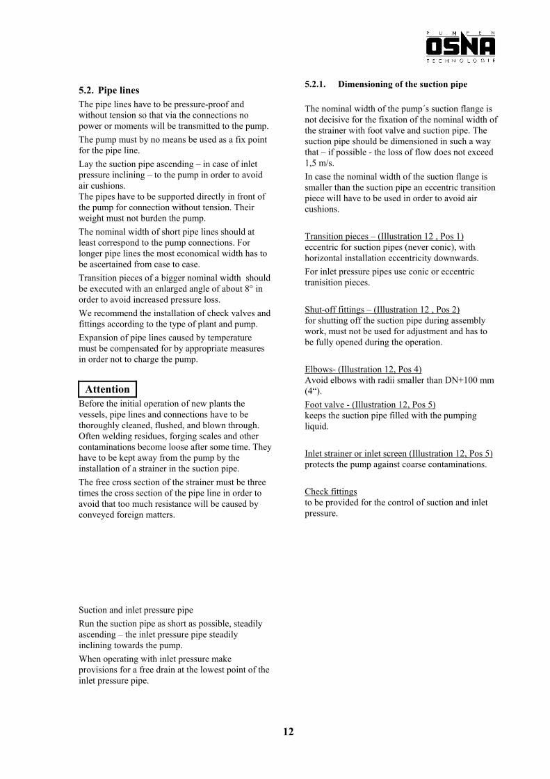
a) Position A ruler placed on the coupling must fully lie upon both halves when being displaced at the circumference by 90° (Illustration 10).
5.1.1 Motor assembly Clean the pump shaft its from rust preventing agent. Fit coupling halves on the pump and motor shaft. Prior to the motor assembly it is advisable to check the direction of rotation acc. to section 6.1.2.
Correct Incorrect
Install the motor on the base plate. Exactly adjust the difference in height of both shafts by supports. The distance between the shafts should not be less than 3 mm. Errors in alignment of the shafts will cause increased wear of the bearings, wear rings, shaft seals, and the flexible elements of the coupling and will result in unsteady operation of the pumping unit.
Illustration 10
b) Direction The axial distance (x) between the coupling halves must be the same anywhere at the circumference. Adjust the coupling distance x to 4 – 5 mm and secure it against axial shifting (Illustration 11).
The pumping unit has been properly aligned when a ruler placed axially on both coupling halves has the same distance to each shaft at the circumference. It is important to turn the measuring point by hand at the same time. Furthermore, both coupling halves must have the same distance to each other anywhere at the circumference. Please check by callipers or gauge.
Incorrect Correct
The centre lines of the pump and motor have to be aligned acc. to their
a) position b) direction.
Both conditions can be achieved by placing or removing sufficiently strong sheet metals under the pump or motor feet. Illustration 11
Tighten the fastening screws of the pump and motor firmly.
After the alignment of the coupling it is absolutely essential to assemble the coupling guard.
11
5.2.1. Dimensioning of the suction pipe 5.2. Pipe lines The pipe lines have to be pressure-proof and without tension so that via the connections no power or moments will be transmitted to the pump.
The nominal width of the pump´s suction flange is not decisive for the fixation of the nominal width of the strainer with foot valve and suction pipe. The suction pipe should be dimensioned in such a way that – if possible - the loss of flow does not exceed 1,5 m/s.
The pump must by no means be used as a fix point for the pipe line. Lay the suction pipe ascending – in case of inlet pressure inclining – to the pump in order to avoid air cushions. The pipes have to be supported directly in front of the pump for connection without tension. Their weight must not burden the pump.
In case the nominal width of the suction flange is smaller than the suction pipe an eccentric transition piece will have to be used in order to avoid air cushions.
The nominal width of short pipe lines should at least correspond to the pump connections. For longer pipe lines the most economical width has to be ascertained from case to case.
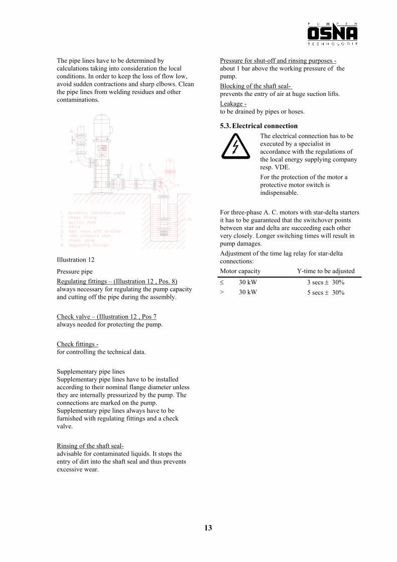
Transition pieces – (Illustration 12 , Pos 1) eccentric for suction pipes (never conic), with horizontal installation eccentricity downwards. For inlet pressure pipes use conic or eccentric tranisition pieces. Transition pieces of a bigger nominal width should
be executed with an enlarged angle of about 8° in order to avoid increased pressure loss.
Shut-off fittings – (Illustration 12 , Pos 2) for shutting off the suction pipe during assembly work, must not be used for adjustment and has to be fully opened during the operation.
We recommend the installation of check valves and fittings according to the type of plant and pump. Expansion of pipe lines caused by temperature must be compensated for by appropriate measures in order not to charge the pump.
Elbows- (Illustration 12, Pos 4) Avoid elbows with radii smaller than DN+100 mm (4“).
Attention Before the initial operation of new plants the vessels, pipe lines and connections have to be thoroughly cleaned, flushed, and blown through. Often welding residues, forging scales and other contaminations become loose after some time. They have to be kept away from the pump by the installation of a strainer in the suction pipe.
Foot valve - (Illustration 12, Pos 5) keeps the suction pipe filled with the pumping liquid. Inlet strainer or inlet screen (Illustration 12, Pos 5) protects the pump against coarse contaminations. The free cross section of the strainer must be three
times the cross section of the pipe line in order to avoid that too much resistance will be caused by conveyed foreign matters.
Check fittings to be provided for the control of suction and inlet pressure. Suction and inlet pressure pipe Run the suction pipe as short as possible, steadily
ascending – the inlet pressure pipe steadily inclining towards the pump.
When operating with inlet pressure make provisions for a free drain at the lowest point of the inlet pressure pipe.
12
The pipe lines have to be determined by calculations taking into consideration the local conditions. In order to keep the loss of flow low, avoid sudden contractions and sharp elbows. Clean the pipe lines from welding residues and other contaminations.
Pressure for shut-off and rinsing purposes - about 1 bar above the working pressure of the pump.
Blocking of the shaft seal- prevents the entry of air at huge suction lifts. Leakage - to be drained by pipes or hoses.
5.3. Electrical connection
The electrical connection has to be executed by a specialist in accordance with the regulations of the local energy supplying company resp. VDE. For the protection of the motor a protective motor switch is indispensable.
For three-phase A. C. motors with star-delta starters it has to be guaranteed that the switchover points between star and delta are succeeding each other very closely. Longer switching times will result in pump damages. Adjustment of the time lag relay for star-delta connections: Illustration 12
Motor capacity Y-time to be adjusted
≤ 30 kW 3 secs ± 30% > 30 kW 5 secs ± 30%
Pressure pipe Regulating fittings – (Illustration 12 , Pos. 8) always necessary for regulating the pump capacity and cutting off the pipe during the assembly.
Check valve – (Illustration 12 , Pos 7 always needed for protecting the pump. Check fittings - for controlling the technical data. Supplementary pipe lines Supplementary pipe lines have to be installed according to their nominal flange diameter unless they are internally pressurized by the pump. The connections are marked on the pump. Supplementary pipe lines always have to be furnished with regulating fittings and a check valve. Rinsing of the shaft seal- advisable for contaminated liquids. It stops the entry of dirt into the shaft seal and thus prevents excessive wear.
13
6. Starting/Putting out of Operation
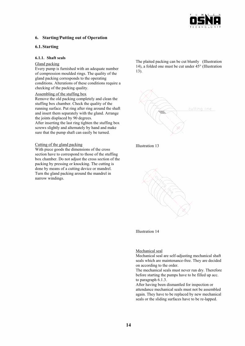
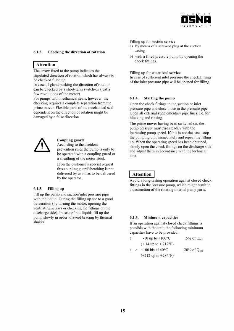
6.1. Starting 6.1.1. Shaft seals The plaited packing can be cut bluntly (Illustration 14), a folded one must be cut under 45° (Illustration 13).
Gland packing Every pump is furnished with an adequate number of compression moulded rings. The quality of the gland packing corresponds to the operating conditions. Alterations of these conditions require a checking of the packing quality.
Assembling of the stuffing box Remove the old packing completely and clean the stuffing box chamber. Check the quality of the running surface. Put ring after ring around the shaft and insert them separately with the gland. Arrange the joints displaced by 90 degrees. After inserting the last ring tighten the stuffing box screws slightly and alternately by hand and make sure that the pump shaft can easily be turned. Cutting of the gland packing With piece goods the dimensions of the cross section have to correspond to those of the stuffing box chamber. Do not adjust the cross section of the packing by pressing or knocking. The cutting is done by means of a cutting device or mandrel. Turn the gland packing around the mandrel in narrow windings.
Illustration 13
Illustration 14 Mechanical seal
Mechanical seal are self-adjusting mechanical shaft seals which are maintenance-free. They are decided on according to the order. The mechanical seals must never run dry. Therefore before starting the pumps have to be filled up acc. to paragraph 6.1.3. After having been dismantled for inspection or attendance mechanical seals must not be assembled again. They have to be replaced by new mechanical seals or the sliding surfaces have to be re-lapped.
14
Filling up for suction service
a) by means of a screwed plug at the suction casing 6.1.2. Checking the direction of rotation b) with a filled pressure pump by opening the check fittings.
Attention The arrow fixed to the pump indicates the stipulated direction of rotation which has always to be checked filled up. In case of gland packing the direction of rotation can be checked by a short-term switch-on (just a few revolutions of the motor). For pumps with mechanical seals, however, the checking requires a complete separation from the prime mover. Flexible parts of the mechanical seal dependent on the direction of rotation might be damaged by a false direction.
Filling up for water feed service In case of sufficient inlet pressure the check fittings of the inlet pressure pipe will be opened for filling.
6.1.4. Starting the pump Open the check fittings in the suction or inlet pressure pipe and close those in the pressure pipe. Open all external supplementary pipe lines, i.e. for blocking and rinsing.
The prime mover having been switched on, the pump pressure must rise steadily with the increasing pump speed. If this is not the case, stop the pumping unit immediately and repeat the filling up. When the operating speed has been obtained, slowly open the check fittings on the discharge side and adjust them in accordance with the technical data.
Coupling guard According to the accident prevention rules the pump is only to be operated with a coupling guard or a sheathing of the motor stool. If on the customer`s special request this coupling guard/sheathing is not delivered by us it has to be delivered by the operator.
AttentionAvoid a long-lasting operation against closed check fittings in the pressure pump, which might result in a destruction of the rotating internal pump parts. 6.1.3. Filling up
Fill up the pump and suction/inlet pressure pipe with the liquid. During the filling up see to a good de-aeration (by turning the motor, opening the ventilating screws or checking the fittings on the discharge side). In case of hot liquids fill up the pump slowly in order to avoid bracing by thermal shocks.
6.1.5. Minimum capacities If an operation against closed check fittings is possible with the unit, the following minimum capacities have to be provided:
t -10 up to +100°C (+ 14 up to + 212°F)
15% of Qopt
t > +100 bis +140°C (+212 up to +284°F)
20% of Qopt
15
6.2.2 Starting the pump again 6.2 Putting out of operation Before starting the pump again check the free movement of the pump. Close the check fittings in the pressure pipe. If a
check valve is fitted into the pressure pipe the check fittings may remain open in case there is counter-pressure.
Remove the gland packing because of the danger of drying up. Dried-up and thus hard packing will damage the shaft sleeve or shaft during the re-start of the pump. Stop the prime mover. Take care that the slow
down is smooth. If the pump was preserved after being stopped it must be flushed before its re-start. For a longer standstill period the check fittings in
the inlet pressure pipe have to be closed. Close supplementary connections.
For pumps that receive liquids under a vacuum the stuffing box has to be provided with the sealing liquid during the standstill period, too.
6.2.1 Draining the pump and frost protection In case of frost danger drain the pump. A pump drained for a longer period must be preserved.
16
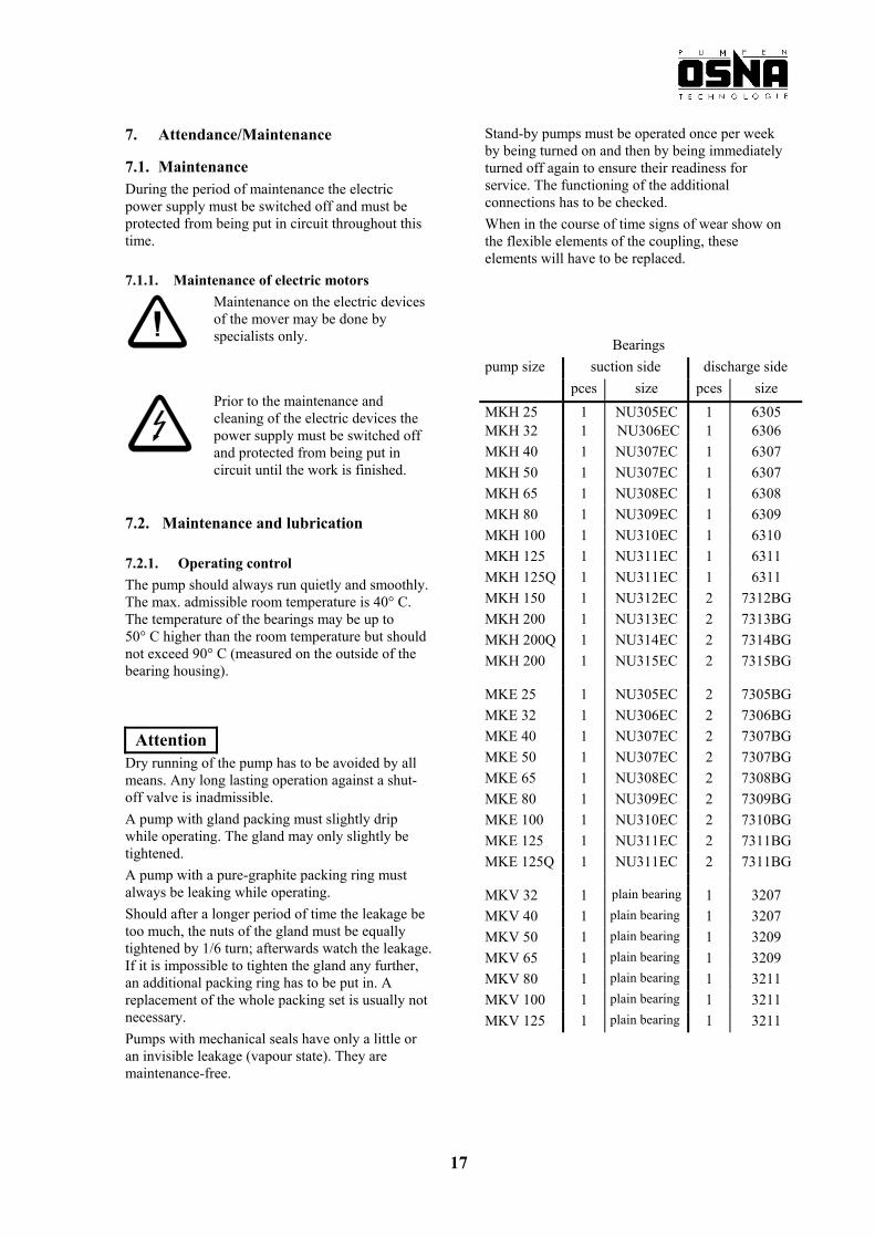
7. Attendance/Maintenance Stand-by pumps must be operated once per week by being turned on and then by being immediately turned off again to ensure their readiness for service. The functioning of the additional connections has to be checked.
7.1. Maintenance During the period of maintenance the electric power supply must be switched off and must be protected from being put in circuit throughout this time.
When in the course of time signs of wear show on the flexible elements of the coupling, these elements will have to be replaced.
7.1.1. Maintenance of electric motors
Maintenance on the electric devices of the mover may be done by specialists only.
Bearings
pump size suction side discharge side pces size pces size MKH 25 1 NU305EC 1 6305MKH 32 1 NU306EC 1 6306 MKH 40 1 NU307EC 1 6307 MKH 50 1 NU307EC 1 6307 MKH 65 1 NU308EC 1 6308 MKH 80 1 NU309EC 1 6309 MKH 100 1 NU310EC 1 6310 MKH 125 1 NU311EC 1 6311 MKH 125Q 1 NU311EC 1 6311 MKH 150 1 NU312EC 2 7312BG MKH 200 1 NU313EC 2 7313BG MKH 200Q 1 NU314EC 2 7314BG MKH 200 1 NU315EC 2 7315BG
MKE 25 1 NU305EC 2 7305BG MKE 32 1 NU306EC 2 7306BG MKE 40 1 NU307EC 2 7307BG MKE 50 1 NU307EC 2 7307BG MKE 65 1 NU308EC 2 7308BG MKE 80 1 NU309EC 2 7309BG MKE 100 1 NU310EC 2 7310BG MKE 125 1 NU311EC 2 7311BG MKE 125Q 1 NU311EC 2 7311BG
MKV 32 1 plain bearing 1 3207 MKV 40 1 plain bearing 1 3207 MKV 50 1 plain bearing 1 3209 MKV 65 1 plain bearing 1 3209 MKV 80 1 plain bearing 1 3211 MKV 100 1 plain bearing 1 3211 MKV 125 1 plain bearing 1 3211
Prior to the maintenance and cleaning of the electric devices the power supply must be switched off and protected from being put in circuit until the work is finished.
7.2. Maintenance and lubrication
7.2.1. Operating control The pump should always run quietly and smoothly. The max. admissible room temperature is 40° C. The temperature of the bearings may be up to 50° C higher than the room temperature but should not exceed 90° C (measured on the outside of the bearing housing).
Attention Dry running of the pump has to be avoided by all means. Any long lasting operation against a shut-off valve is inadmissible. A pump with gland packing must slightly drip while operating. The gland may only slightly be tightened. A pump with a pure-graphite packing ring must always be leaking while operating. Should after a longer period of time the leakage be too much, the nuts of the gland must be equally tightened by 1/6 turn; afterwards watch the leakage. If it is impossible to tighten the gland any further, an additional packing ring has to be put in. A replacement of the whole packing set is usually not necessary. Pumps with mechanical seals have only a little or an invisible leakage (vapour state). They are maintenance-free.
17
Oil characteristics acc. to ISO VG kinematic viscosity at 40° C : 7.2.2. Lubrication min. 40 mm² / s
7.2.2.1. Grease change max. 70 mm² / s − Horizontal pumps MKH: grease lubricated
radial ball bearings − Vertical pumps MKV: grease lubricated radial
ball bearings and bearing bush greased by the liquid
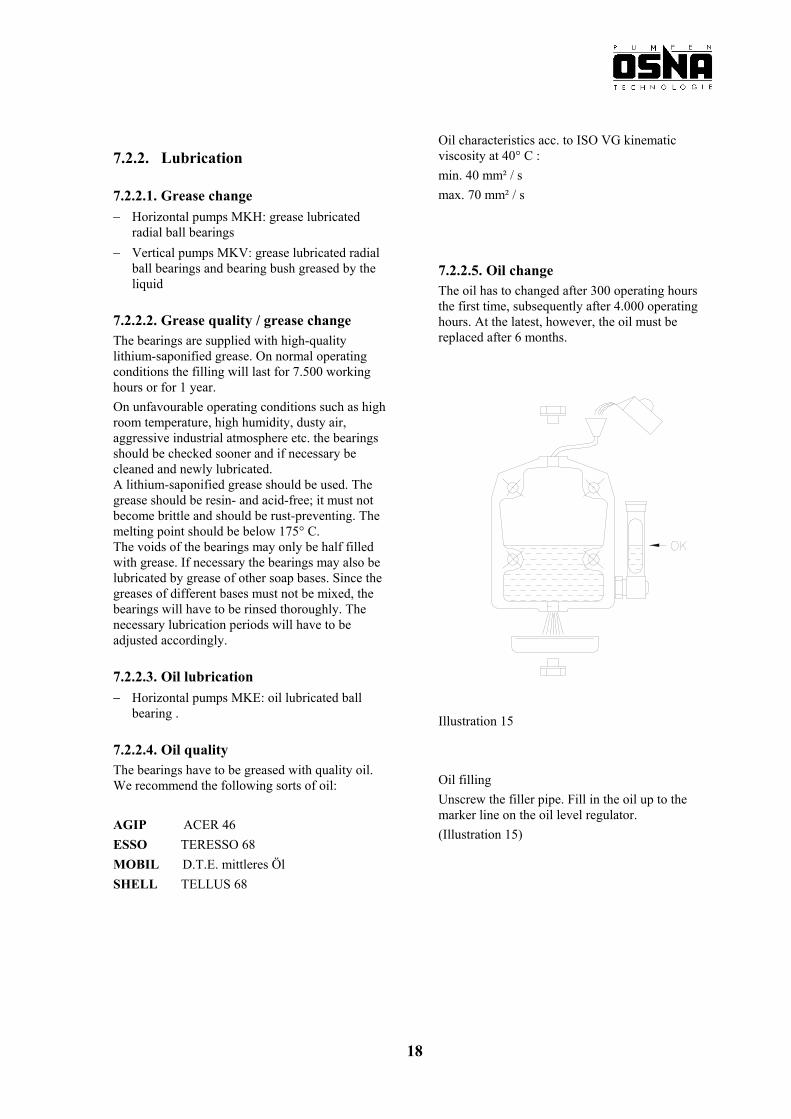
7.2.2.5. Oil change The oil has to changed after 300 operating hours the first time, subsequently after 4.000 operating hours. At the latest, however, the oil must be replaced after 6 months.
7.2.2.2. Grease quality / grease change The bearings are supplied with high-quality lithium-saponified grease. On normal operating conditions the filling will last for 7.500 working hours or for 1 year.
On unfavourable operating conditions such as high room temperature, high humidity, dusty air, aggressive industrial atmosphere etc. the bearings should be checked sooner and if necessary be cleaned and newly lubricated. A lithium-saponified grease should be used. The grease should be resin- and acid-free; it must not become brittle and should be rust-preventing. The melting point should be below 175° C. The voids of the bearings may only be half filled with grease. If necessary the bearings may also be lubricated by grease of other soap bases. Since the greases of different bases must not be mixed, the bearings will have to be rinsed thoroughly. The necessary lubrication periods will have to be adjusted accordingly.
7.2.2.3. Oil lubrication − Horizontal pumps MKE: oil lubricated ball
bearing . Illustration 15 7.2.2.4. Oil quality
The bearings have to be greased with quality oil. We recommend the following sorts of oil: Oil filling
Unscrew the filler pipe. Fill in the oil up to the marker line on the oil level regulator.
AGIP ACER 46
(Illustration 15) ESSO TERESSO 68
MOBIL D.T.E. mittleres Öl
SHELL TELLUS 68
18
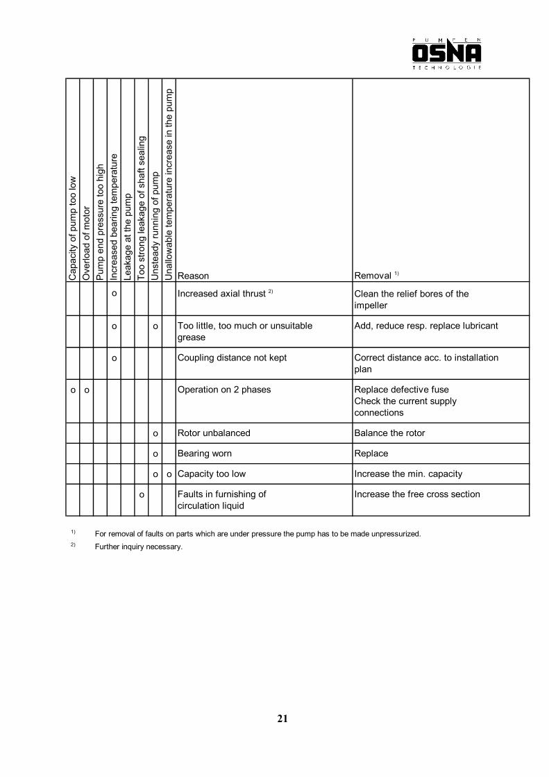
8. Faults / Reasons / Removal C
apac
ity o
f pum
p to
o lo
wO
verlo
ad o
f mot
orPu
mp
end
pres
sure
too
high
Incr
ease
d be
arin
g te
mpe
ratu
reLe
akag
e at
the
pum
pTo
o st
rong
leak
age
of s
haft
seal
ing
Uns
tead
y ru
nnin
g of
pum
pU
nallo
wab
le te
mpe
ratu
re in
crea
se in
the
pum
p
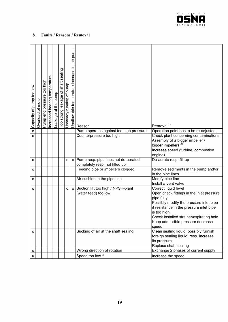
Reason Removal 1)
o Pump operates against too high pressure Operation point has to be re-adjustedo Counterpressure too high Check plant concerning contaminations
Assembly of a bigger impeller /bigger impellers 2)
Increase speed (turbine, combustionengine)
o o o Pump resp. pipe lines not de-aerated De-aerate resp. fill upcompletely resp. not filled up
o Feeding pipe or impellers clogged Remove sediments in the pump and/orin the pipe lines
o Air cushion in the pipe line Modify pipe lineInstall a vent valve
o o o Suction lift too high / NPSH-plant Correct liquid level(water feed) too low Open check fittings in the inlet pressure
pipe fullyPossibly modify the pressure inlet pipeif resistance in the pressure inlet pipeis too highCheck installed strainer/aspirating holeKeep admissible pressure decreasespeed
o Sucking of air at the shaft sealing Clean sealing liquid, possibly furnishforeign sealing liquid, resp. increaseits pressureReplace shaft sealing
o Wrong direction of rotation Exchange 2 phases of current supplyo Speed too low 2) Increase the speed
19
C
apac
ity o
f pum
p to
o lo
wO
verlo
ad o
f mot
orPu
mp
end
pres
sure
too
high
Incr
ease
d be
arin
g te
mpe
ratu
reLe
akag
e at
the
pum
pTo
o st
rong
leak
age
of s
haft
seal
ing
Uns
tead
y ru
nnin
g of
pum
pU
nallo
wab
le te
mpe
ratu
re in
crea
se in
the
pum
p
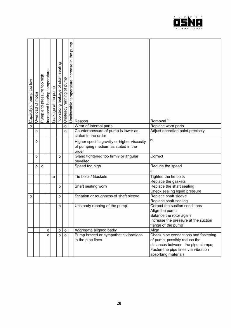
Reason Removal 1)
o o Wear of internal parts Replace worn partso o Counterpressure of pump is lower as Adjust operation point precisely
stated in the ordero Higher specific gravity or higher viscosity 2)
of pumping medium as stated in theorder
o o Gland tightened too firmly or angular Correctbevelled
o o Speed too high Reduce the speed2)
o Tie bolts / Gaskets Tighten the tie boltsReplace the gaskets
o Shaft sealing worn Replace the shaft sealingCheck sealing liquid pressure
o o Striation or roughness of shaft sleeve Replace shaft sleeveReplace shaft sealing
o Unsteady running of the pump Correct the suction conditionsAlign the pumpBalance the rotor againIncrease the pressure at the suctionflange of the pump
o o o Aggregate aligned badly Aligno o o Pump braced or sympathetic vibrations Check pipe connections and fastening
in the pipe lines of pump, possibly reduce the distances between the pipe clamps;Fasten the pipe lines via vibrationabsorbing materials
20
Cap
acity
of p
ump
too
low
Ove
rload
of m
otor
Pum
p en
d pr
essu
re to
o hi
ghIn
crea
sed
bear
ing
tem
pera
ture
Leak
age
at th
e pu
mp
Too
stro
ng le
akag
e of
sha
ft se
alin
gU
nste
ady
runn
ing
of p
ump
Una
llow
able
tem
pera
ture
incr
ease
in th
e pu
mp
Reason Removal 1)
o Increased axial thrust 2) Clean the relief bores of the impeller
o o Too little, too much or unsuitable Add, reduce resp. replace lubricantgrease
o Coupling distance not kept Correct distance acc. to installationplan
o o Operation on 2 phases Replace defective fuseCheck the current supplyconnections
o Rotor unbalanced Balance the rotor
o Bearing worn Replace
o o Capacity too low Increase the min. capacity
o Faults in furnishing of Increase the free cross sectioncirculation liquid
1) For removal of faults on parts which are under pressure the pump has to be made unpressurized.2) Further inquiry necessary.
21
Service, Spare Parts, Accessories We expressly draw your attention to the fact that spare parts and accessories not delivered by us have not been controlled and approved of by us either. The installation and/or the utilization of such products may possibly affect characteristic features of the centrifugal pump in a negative way and thus impair safety. For damages resulting from the use of not genuine spare parts and accessories OSNA does not assume any liability and warranty. Breakdowns that you cannot repair yourself must only be remedied by the OSNA service technicians or a specialised company. Please give us an exact description of the damage thus enabling our technicians to prepare and provide themselves with the respective spare parts. You can contact our Service Department by the address mentioned on the last page. Spare parts can be ordered directly. The model designation is given on the data plate.
The following spare part drawings only serve the purpose of identifying the spare parts and their respective procurement.
The exploded views must not be used as assembly instructions.
Comments on spare part orders: In order to avoid faulty deliveries we kindly ask you for exact order instructions − order number of the pump − part designation − quantity required − method of dispatch (e. g. parcel post, freight,
express goods, express, courier service) − exact delivery address
22