Embed Size (px)
Citation preview
Tray Handling Systems
ASYS TECTON – Tray Handling and Transfer Systems
PARIO500_170623_DS_CC_E
PARIO 500
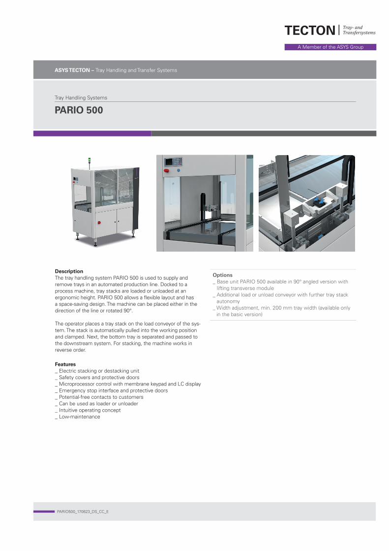
DescriptionThe tray handling system PARIO 500 is used to supply and remove trays in an automated production line. Docked to a process machine, tray stacks are loaded or unloaded at an ergonomic height. PARIO 500 allows a fl exible layout and has a space-saving design. The machine can be placed either in the direction of the line or rotated 90°.
The operator places a tray stack on the load conveyor of the sys-tem. The stack is automatically pulled into the working position and clamped. Next, the bottom tray is separated and passed to the downstream system. For stacking, the machine works in reverse order.
Features_ Electric stacking or destacking unit_ Safety covers and protective doors_ Microprocessor control with membrane keypad and LC display_ Emergency stop interface and protective doors_ Potential-free contacts to customers_ Can be used as loader or unloader_ Intuitive operating concept_ Low-maintenance
Options_ Base unit PARIO 500 available in 90° angled version with
lifting transverse module_ Additional load or unload conveyor with further tray stack
autonomy_ Width adjustment, min. 200 mm tray width (available only
in the basic version)
www.asys-tecton.com
ASYS Group ASYS TECTON GmbHWaldstraße 16, 78087 Mönchweiler, Germany Tel (+49) 7721 99245 0 Fax (+49) 7721 99245 10 [email protected]
Subject to change without notice. Some generaldescriptions and performance characteristicsmay not be applicable to all products. Technicalspecifications are subject to change without notice.Only features and technical data provided inpurchasing contract are legally binding.
Printed in Germany. The pictures may contain optional extras, custom fittings or accessories which are not included in the standard scope of delivery. These are available at extra cost.
DepanelingTray handling
Depaneling
Tray handling
06.03.15WipfÄnderung /
Produktmechanik Pario 500
100111433 910.49.914
A1
Wipf 06.03.15Gez.:Bearb:Gepr.: Schutzvermerk nach DIN 34 beachten Ersatz fuer/durch:
Zeichn.-Nr.:Dok.Id. / Workflow
ISO 2768 - mKAllgemeintoleranz
Format Maßstab Werkstoff:
Benennung:
Halbzeug:Rev AE-Text1 NameDatum
IS0 13920 - A / EAllg. Schweißtoleranz
ISO 1302 Reihe 2Oberflächen
Blatt von
Rev.:Artikel - Nr.:49.910.914
Oberfläche:
Gewicht : KG0.00 /
Pos. Menge ME ArtikelNr. Benennung short descrip.
10 16.00 Stk 04.002.047 DIN EN ISO 4762 M6x128.8 DIN EN ISO 4762 M6x128.8
20 1.00 Stk 04.004.008 DIN EN ISO 4017 M6x168.8 DIN EN ISO 4017 M6x168.8
30 4.00 Stk 04.004.009 DIN EN ISO 4017 M6x208.8 DIN EN ISO 4017 M6x208.8
40 5.00 Stk 04.009.008 DIN EN ISO 7089 6,4140HV DIN EN ISO 7089 6,4140HV
50 1.00 Stk 10.910.1042 Rahmen gesamt frame complete
60 1.00 Stk 25.910.094 Aushubeinheit lift out unit
70 1.00 Stk 25.910.095 Gesamtmechanik Kurzhubband
80 1.00 Stk 70.001.035 Warnung vor Handverletzungsgefa warning sign sticker
90 1.00 Stk 10.1400.666 Abdeckblech
100 1.00 Stk 10.1400.667 Abdeckblech
110 1.00 Stk 10.1400.664 Abdeckblech
120 4.00 Stk 10.325.029 Stellfußerhöhung Machine leg extension d= 70
130 4.00 Stk 10.325.027 Flansch flange
140 4.00 Stk 50.048.001 Stellfuß M16x160mm Adjustable foot M16x160mm
1450
880
1789
880 1450
910
220
400600
52,25
196
1563
196
79,5
1789
910
220
880
400-600
1450
06.03.15WipfÄnderung /
Produktmechanik Pario 500
100111433 910.49.914
A1
Wipf 06.03.15Gez.:Bearb:Gepr.: Schutzvermerk nach DIN 34 beachten Ersatz fuer/durch:
Zeichn.-Nr.:Dok.Id. / Workflow
ISO 2768 - mKAllgemeintoleranz
Format Maßstab Werkstoff:
Benennung:
Halbzeug:Rev AE-Text1 NameDatum
IS0 13920 - A / EAllg. Schweißtoleranz
ISO 1302 Reihe 2Oberflächen
Blatt von
Rev.:Artikel - Nr.:49.910.914
Oberfläche:
Gewicht : KG0.00 /
Pos. Menge ME ArtikelNr. Benennung short descrip.
10 16.00 Stk 04.002.047 DIN EN ISO 4762 M6x128.8 DIN EN ISO 4762 M6x128.8
20 1.00 Stk 04.004.008 DIN EN ISO 4017 M6x168.8 DIN EN ISO 4017 M6x168.8
30 4.00 Stk 04.004.009 DIN EN ISO 4017 M6x208.8 DIN EN ISO 4017 M6x208.8
40 5.00 Stk 04.009.008 DIN EN ISO 7089 6,4140HV DIN EN ISO 7089 6,4140HV
50 1.00 Stk 10.910.1042 Rahmen gesamt frame complete
60 1.00 Stk 25.910.094 Aushubeinheit lift out unit
70 1.00 Stk 25.910.095 Gesamtmechanik Kurzhubband
80 1.00 Stk 70.001.035 Warnung vor Handverletzungsgefa warning sign sticker
90 1.00 Stk 10.1400.666 Abdeckblech
100 1.00 Stk 10.1400.667 Abdeckblech
110 1.00 Stk 10.1400.664 Abdeckblech
120 4.00 Stk 10.325.029 Stellfußerhöhung Machine leg extension d= 70
130 4.00 Stk 10.325.027 Flansch flange
140 4.00 Stk 50.048.001 Stellfuß M16x160mm Adjustable foot M16x160mm
1450
880
1789
880 1450
910
220
400600
52,25
19615
63
196
79,5
1563
PARIO 500
Basis 0 ° 90 °
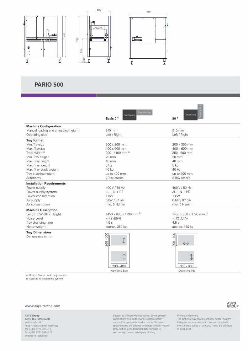
Machine ConfigurationManual loading and unloading heightOperating side
910 mmLeft / Right
910 mmLeft / Right
Tray formatMin. TraysizeMax. TraysizeTrack width a) Min. Tray heightMax. Tray heightMax. Tray weightMax. Tray stack weightTray stacking heightAutonomy
200 x 200 mm400 x 600 mm200 - 4100 mm a)
20 mm40 mm5 kg40 kgup to 400 mm2 Tray stacks
200 x 350 mm400 x 600 mm350 - 600 mm20 mm40 mm5 kg40 kgup to 400 mm3 Tray stacks
Installation RequirementsPower supplyPower supply systemPower consumptionAir supplyAir consumption
400 V / 50 Hz3L + N + PE1 kW6 bar / 87 psimin. 5 Nl/min
400 V / 50 Hz3L + N + PE1 kW6 bar / 87 psimin. 5 Nl/min
Machine DescriptionLength x Width x HeightNoise LevelTray changing timeNetto weight
1450 x 880 x 1790 mm b)
< 72 dB(A)4,5 sapprox. 350 kg
1450 x 880 x 1790 mm b)
< 72 dB(A)4,5 sapprox. 350 kg
Tray Dimensions Dimensions in mm
a) Option: Electric width adjustmentb) Adapted to depaneling system
350 - 600
200
- 400
200 - 400
200
- 600
Operating Side Operating Side

![WELDING REQUIREMENTS [REP] - Tecton Services, …tectoninc.com/wp-content/uploads/tecton-web-projects... · Web viewRadiography on all joints per ANSI B31.1, latest revision, Chapter](https://img.pdfslide.net/doc/110x75/5a9e6cd07f8b9a67178b585f/docwelding-requirements-rep-tecton-services-viewradiography-on-all-joints.jpg)