Embed Size (px)
Citation preview
AT-FM-10K Two-Hand Control ModuleDUO-TOUCH® SG, for use with two actuating devicesOriginal Instructions
• Diverse-redundant microcontrollers• Monitors two Banner STB Self-Checking Optical Touch Buttons, or two mechanical
push buttons• Two redundant, forced-guided (mechanically linked) output contacts rated at 6 A• Feedback input monitors external machine control elements• 5 indicator LEDs for Power, Fault, Input 1, Input 2 and Output• 24V ac/dc operation• DIN-rail-mountable 22.5 mm-wide housing with removable terminal blocks• 500 ms (max.) simultaneity requirement for touch-/push button operation
Important . . . Read This Before Proceeding!It is the responsibility of the machine designer, controls engineer, machine builder and/or maintenance electrician to apply and maintainthis product in full compliance with all applicable regulations and standards. The product can provide the required safeguarding functiononly if it is properly installed, properly operated, and properly maintained. This manual attempts to provide complete installation, opera-tional, and maintenance instruction. Reading the manual completely is highly recommended. Please direct any questions regarding theapplication or use of the product to a Banner Engineering Applications Engineer at the locations listed in this document.
WARNING: User ResponsibilityThe user is responsible for ensuring that all local, state, and national laws, rules, codes, and regulationsrelating to the use of this device in any particular application are satisfied. Make sure that all legal require-ments have been met and that all installation, operation, and maintenance instructions contained in thedevice documentation are followed.
U.S. Application StandardsANSI B11.0 Safety of Machinery; General Requirements and Risk AssessmentANSI B11.19 Performance Criteria for SafeguardingANSI NFPA 79 Electrical Standard for Industrial Machinery
International/European StandardsISO TR12100-1 & -2 (EN 292-1 & -2) Safety of Machinery – Basic Concepts, General Principles for Design
IEC 60204-1 Electrical Equipment of Machines Part 1: General Requirements
ISO 13849-1 (EN 954-1) Safety-Related Parts of Control Systems
ISO 13855 (EN 999) The Positioning of Protective Equipment in Respect to Approach Speeds of Parts of the Human Body
ISO 13851 (EN 574) Two-Hand Control Devices – Functional Aspects – Principles for Design (also request a type "C" standard for yourspecific machinery.)
AT-FM-10K Two-Hand Control Module
P/N 64137 Rev. G 1/31/2013
Sources of Standards and RegulationsOSHA Documents: www.osha.gov (Tel: 202-512-1800)American National Standards Institute (ANSI): www.ansi.org (Tel: 212-642-4900)Robotics Industries Association (RIA): www.robotics.org (Tel: 734-994-6088)National Fire Protection Association (NFPA): www.nfpa.org (Tel: 800-344-3555)NSSN National Resource for Global Standards : www.nssn.org (Tel: 212-642-4980)IHS Standards Store: www.global.ihs.com (Tel: 303-397-7956, 800-854-7179)Document Center: www.document-center.com/home.cfm (Tel: 650-591-7600)
EC Declaration of ConformityBanner Enginering Corp. herewith declares that AT-FM-10K Two-Hand Control Module for industrial control is in conformity with theprovisions of the Machinery Directive (Directive 98/37/EEC), and all essential Health and Safety Requirements have been met.Download the complete EC Declaration of Conformity as a PDF file at www.bannerengineering.com/THCmodule
OverviewA DUO-TOUCH SG Two-Hand Control Safety Module (the “Module”) may be used with:
• Two Banner STB Self-Checking Optical Touch Buttons, each with one normally open and one normally closed relay output contact, or• Two Banner STB Self-Checking Optical Touch Buttons, each with two current-sourcing PNP outputs, or• Two electro-mechanical push buttons, each with one normally open and one normally closed contact (Form C contact)
If the machine operator removes one or both hands from the actuating device(s), the Module relays de-energize, causing the outputcontacts to open. The relays will not re-energize until both actuating devices are deactivated and then simultaneously reactivated.
WARNING: Point-of-Operation GuardingWhen properly installed, a two-hand control device provides protection only for the hands of the machineoperator. It may be necessary to install additional safeguarding, such as safety light screens, addition-al two-hand controls, and/or hard guards, to protect all individuals from hazardous machinery.Failure to properly guard hazardous machinery can result in a dangerous condition which couldlead to serious injury or death.
The Duo-Touch SG® Two-Hand Control Kit system complies with:• Two-hand control and Control Reliability requirements per OSHA 29CFR1910.217, ANSI NFPA 79, ANSI B11.19, and ANSI/RIA
R15.06,• Type IIIC requirements of ISO 13851 (EN 574) Safety of Machinery – Two-Hand Control Devices, and• Safety-related applications up to Category 4 PL e, per EN ISO 13849-1 and SIL3 per IEC 61508 and IEC 62061.
The Safety Module’s output signal consists of two sets of redundant, forced-guided (mechanically linked) contacts (see wiring diagrams).Circuitry within the Safety Module monitors these internal contacts and prevents an output signal from occurring if a fault is detected. Afeedback loop is offered for monitoring the status of the machine control elements.
AT-FM-10K Two-Hand Control Module
2 www.bannerengineering.com - tel: 763-544-3164 P/N 64137 Rev. G
LED Indicators
S12A1
S11 S13
S23 S21 S22
13 23 Y1
Y2 14 24 A2
K1
K2
14 24
13 23
MachineSafety
AT-FM-10K
Power
Fault
In 1
In 2
Output
S12 S11 S13
A1 13 23 Y1
S23 S21 S22
Y2 14 24 A2
Power ON(green)
Input 1 Status (green)
Internal Fault (red)
Input 2 Status (green)
Output Status (green)
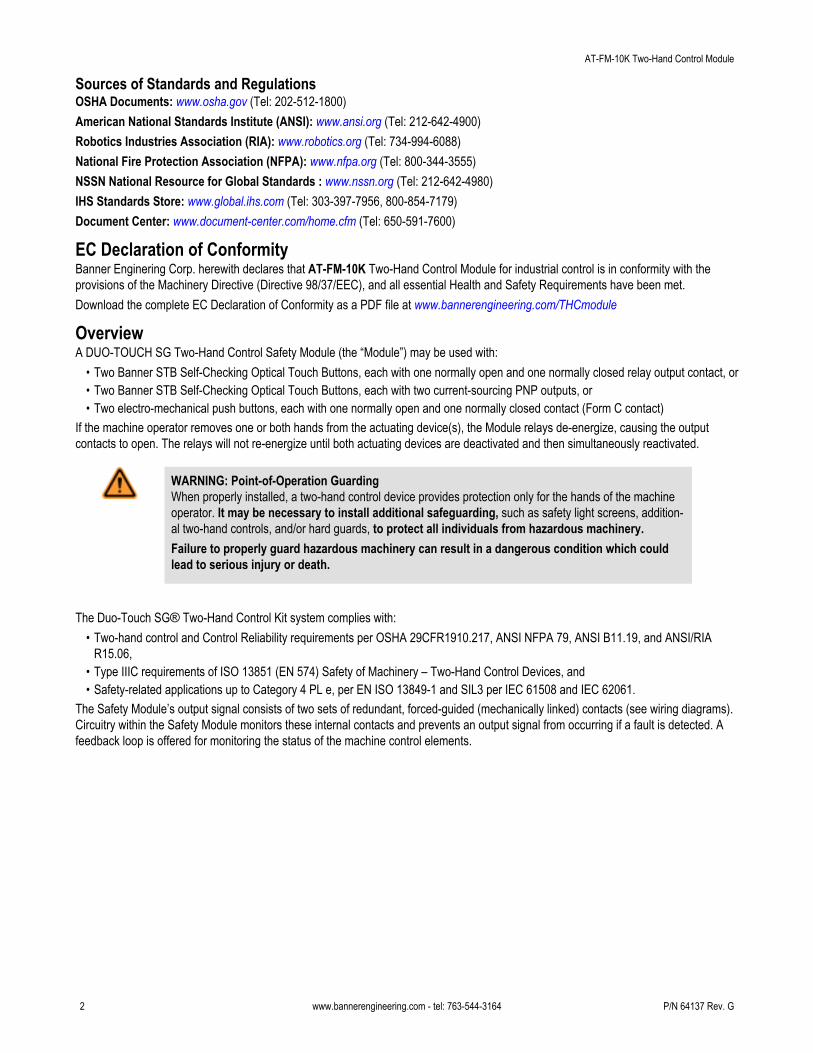
Figure 1. Status indicators and terminal locations
LED ON OFF Flashing
Power ON Power is applied No power —
Fault Simultaneity isnot met orExternal wiringfault
— Internal faultcondition is de-tected
Input 1 StatusInput 2 Status
Touch button isactivated
Button is not ac-tivated
External wiringfault is detected
Output Status Both relays (K1and K2) areenergized
— Feedback error
Module Operation
CAUTION: Not an Anti-Repeat Control DeviceAnti-repeat control is not a function of this Two-Hand Control Safety Module. The user of this devicemust provide a suitable means of accomplishing anti-repeat control for any single-stroke or single-cyclemachine.
The Two-Hand Control Safety Module may be used as an initiation device for most powered machinery when machine cycling is control-led by a machine operator.Using a two-hand control system makes the operator a “hostage” while the hazard is present, thus limiting or preventing exposure to thehazard. The two-hand control actuators must be located in a way that hazardous motion is completed or stopped before the operator canrelease one or both of the buttons and reach the hazard (see Separation Distance).The Safety Module’s safety inputs are used to monitor the actuation of the hand controls to comply with the functionality of Type IIIrequirements of IEC60204-1 and ISO 13851 (Type IIIa/Cat 4) and the requirements of ANSI NFPA79 and ANSI B11.19 for two-handcontrol, which include:
• Concurrent (simultaneous) actuation by both hands within a 500 ms time frame• Where this time limit is exceeded, a requirement that both hand controls must be released before operation is initiated• Continuous actuation during hazardous condition• Cessation of hazardous condition if either hand control was released• Release and re-actuation of both hand controls to re-initiate the hazardous motion or condition (i.e., “anti-tie down”)• The appropriate performance level of the safety-related function (e.g., Control Reliability, Category/Performance Level, or SIL) as
determined by a risk assessment or the applicable regulation and standards.
AT-FM-10K Two-Hand Control Module
P/N 64137 Rev. G www.bannerengineering.com - tel: 763-544-3164 3
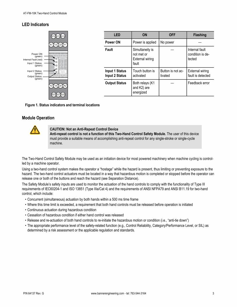
In addition, the Safety Module logic will not permitthe safety outputs to turn ON when power is initiallysupplied and if the hand controls (actuators) are intheir Run state (e.g. both actuators tie-down). Thehand controls must change to their Stop state andreturn to the Run state before the safety outputscan turn ON.The actuating devices must be protected from acci-dental or unintended operation. This can be ac-complished by their mounting position and/orthrough the use of protective shields such as rings,guards or shields; see Mechanical Installation.
Power
< 0.5 s < 0.5 s Feedback Open SW1 tied down SW2 tied down
FeedbackLoop*
SW1
SW2
Output
> 0.5 s
Figure 2. Model AT-FM-10K timing logic
Part- and Full-Revolution Clutched MachineryWhen used on part-revolution clutched machinery that can be stopped at any point during the cycle, the Safety Module can be usedfor the following function types: “inch” (jog), “single-stroke,” or “continuous” (run).When used on full-revolution clutched machinery (that can not be stopped until the end of the cycle), the Safety Module is used toinitiate the cycle and is known as a “two-hand trip device.”In either situation, the hand controls must be safely located and protected from false operation (see Mechanical Installation and Separa-tion Distance) and the Safety Module must be appropriately interfaced to the machine (see Electrical Installation).When used in single-cycle or single-stroke mode, the machine control must provide an anti-repeat feature so that the operator mustrelease the two-hand control actuators after each machine cycle, before a new cycle can be initiated.
NOTE: Two-hand control and two-hand trip safeguarding protect only the operator’s hands . Additional safe-guarding (e.g., additional two-hand controls) may be required. Refer to the relevant standards for addition-al requirements.
Mechanical InstallationInstall the Safety Module inside an enclosure rated NEMA 3 (IEC IP54), or better. It is not designed for exposed wiring. The Modulemounts directly onto a standard 35 mm DIN rail.
Heat Dissipation ConsiderationsFor reliable operation, ensure that the operating specifications are not exceeded. The enclosure must provide adequate heat dissipation,so that the air closely surrounding the Module does not exceed the maximum operating temperature stated in the Specifications. Methodsto reduce heat build-up include venting, forced airflow (e.g., exhaust fans), adequate enclosure exterior surface area, and spacing be-tween modules and other sources of heat.
Installation of Hand Controls
CAUTION: Hand ControlsThe environment in which hand controls are installed must not adversely affect the means of ac-tuation. Severe contamination or other environmental influences may cause slow response or false ONconditions of mechanical or ergonomic buttons. This may result in exposure to a hazard.
CAUTION: Install Hand Controls to Prevent Accidental ActuationTotal protection for the two-hand control system from “defeat” is not possible. However, the user is re-quired by OSHA regulations to arrange and protect hand controls to minimize possibility of defeator accidental actuation.
AT-FM-10K Two-Hand Control Module
4 www.bannerengineering.com - tel: 763-544-3164 P/N 64137 Rev. G
Each actuating device requires a normally open and a normally closed (e.g., Form C or SPDT) hard contact, each capable of reliablyconducting 25 mA at 24V dc (nominal). For complementary PNP operation, model STBVP.. touch buttons must be used to ensure properfunctionality.Standards require that the actuating devices be mounted to protect them from accidental or unintentional operation. Use shields, covers,rings, collars, dividers, or similar protection to prevent accidental switch actuation and to discourage use of forearms or elbows. Europeanstandard ISO13851 includes a detailed discussion of approaches to protection of hand controls.The installation of the hand controls must also consider:
• Failure modes that would result in a short circuit, a broken spring(s), mechanical seizure, etc. that would result in not detecting therelease of a hand control.
• Severe contamination or other environmental influences that may cause slow response when released or false ON condition of thehand control(s), e.g., sticking of a mechanical linkage.
The hand controls must be arranged far enough apart so that the operator cannot operate both hand controls by the use of one arm.Typically, this distance is not less than 550 mm/21.7” in a straight line, but using guards or alternate mounting arrangement can allowshorter distances, per ISO13851 (EN574). This standard also recommends that the hand controls be arranged on a horizontal (or nearlyhorizontal) surface that is 1,100 mm/43.3" above the floor for ergonomic purposes.
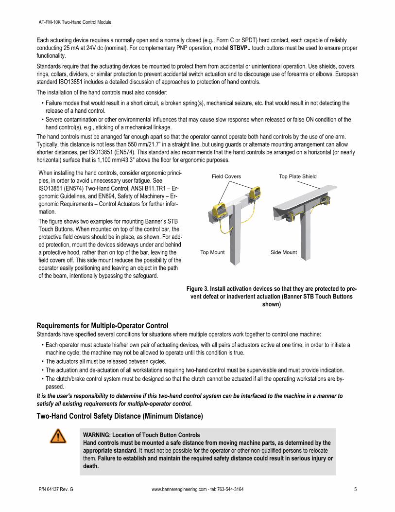
When installing the hand controls, consider ergonomic princi-ples, in order to avoid unnecessary user fatigue. SeeISO13851 (EN574) Two-Hand Control, ANSI B11.TR1 – Er-gonomic Guidelines, and EN894, Safety of Machinery – Er-gonomic Requirements – Control Actuators for further infor-mation.The figure shows two examples for mounting Banner’s STBTouch Buttons. When mounted on top of the control bar, theprotective field covers should be in place, as shown. For add-ed protection, mount the devices sideways under and behinda protective hood, rather than on top of the bar, leaving thefield covers off. This side mount reduces the possibility of theoperator easily positioning and leaving an object in the pathof the beam, intentionally bypassing the safeguard.
Field Covers
Top Mount Side Mount
Top Plate Shield
Figure 3. Install activation devices so that they are protected to pre-vent defeat or inadvertent actuation (Banner STB Touch Buttons
shown)
Requirements for Multiple-Operator ControlStandards have specified several conditions for situations where multiple operators work together to control one machine:
• Each operator must actuate his/her own pair of actuating devices, with all pairs of actuators active at one time, in order to initiate amachine cycle; the machine may not be allowed to operate until this condition is true.
• The actuators all must be released between cycles.• The actuation and de-actuation of all workstations requiring two-hand control must be supervisable and must provide indication.• The clutch/brake control system must be designed so that the clutch cannot be actuated if all the operating workstations are by-
passed.It is the user's responsibility to determine if this two-hand control system can be interfaced to the machine in a manner tosatisfy all existing requirements for multiple-operator control.
Two-Hand Control Safety Distance (Minimum Distance)
WARNING: Location of Touch Button ControlsHand controls must be mounted a safe distance from moving machine parts, as determined by theappropriate standard. It must not be possible for the operator or other non-qualified persons to relocatethem. Failure to establish and maintain the required safety distance could result in serious injury ordeath.
AT-FM-10K Two-Hand Control Module
P/N 64137 Rev. G www.bannerengineering.com - tel: 763-544-3164 5
U.S. Applications European Applications
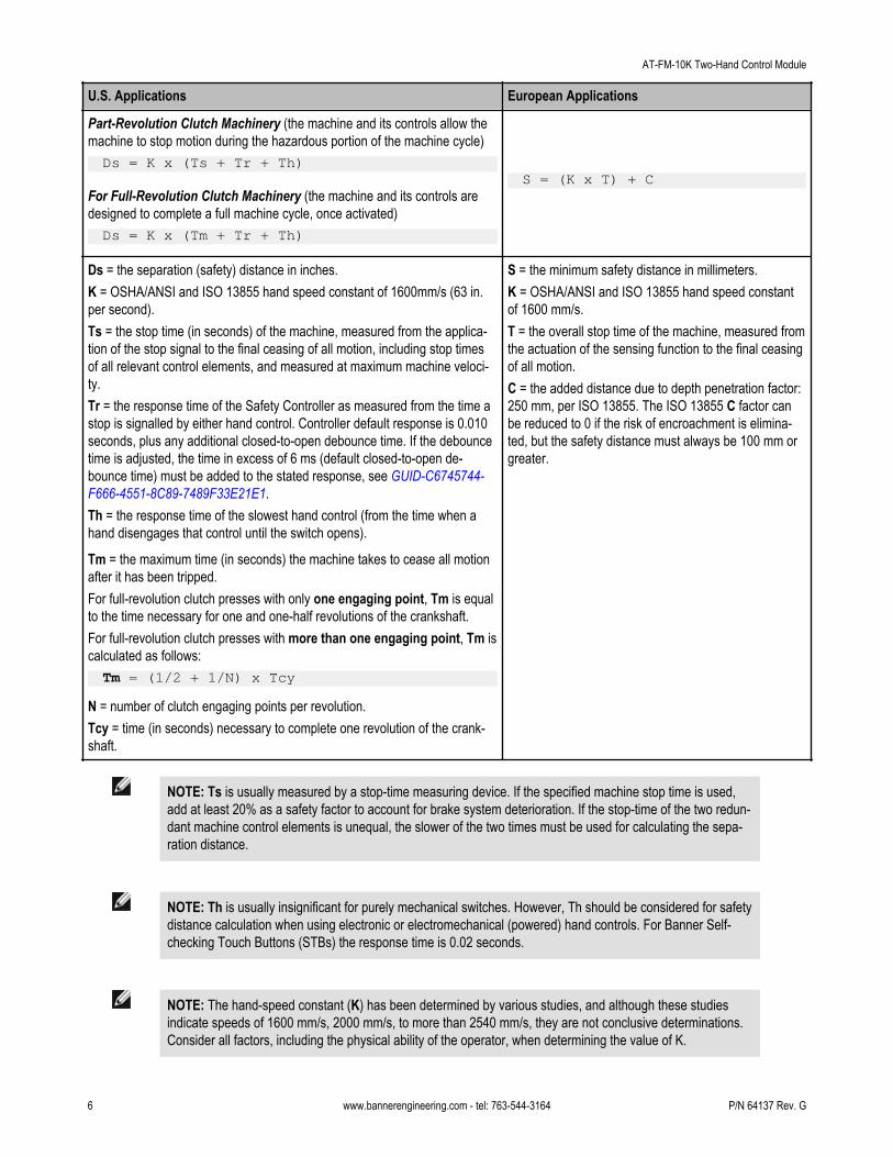
Part-Revolution Clutch Machinery (the machine and its controls allow themachine to stop motion during the hazardous portion of the machine cycle)Ds = K x (Ts + Tr + Th)
S = (K x T) + CFor Full-Revolution Clutch Machinery (the machine and its controls aredesigned to complete a full machine cycle, once activated)Ds = K x (Tm + Tr + Th)
Ds = the separation (safety) distance in inches.K = OSHA/ANSI and ISO 13855 hand speed constant of 1600mm/s (63 in.per second).Ts = the stop time (in seconds) of the machine, measured from the applica-tion of the stop signal to the final ceasing of all motion, including stop timesof all relevant control elements, and measured at maximum machine veloci-ty.Tr = the response time of the Safety Controller as measured from the time astop is signalled by either hand control. Controller default response is 0.010seconds, plus any additional closed-to-open debounce time. If the debouncetime is adjusted, the time in excess of 6 ms (default closed-to-open de-bounce time) must be added to the stated response, see GUID-C6745744-F666-4551-8C89-7489F33E21E1.Th = the response time of the slowest hand control (from the time when ahand disengages that control until the switch opens).
Tm = the maximum time (in seconds) the machine takes to cease all motionafter it has been tripped.For full-revolution clutch presses with only one engaging point, Tm is equalto the time necessary for one and one-half revolutions of the crankshaft.For full-revolution clutch presses with more than one engaging point, Tm iscalculated as follows:
Tm = (1/2 + 1/N) x TcyN = number of clutch engaging points per revolution.Tcy = time (in seconds) necessary to complete one revolution of the crank-shaft.
S = the minimum safety distance in millimeters.K = OSHA/ANSI and ISO 13855 hand speed constantof 1600 mm/s.T = the overall stop time of the machine, measured fromthe actuation of the sensing function to the final ceasingof all motion.C = the added distance due to depth penetration factor:250 mm, per ISO 13855. The ISO 13855 C factor canbe reduced to 0 if the risk of encroachment is elimina-ted, but the safety distance must always be 100 mm orgreater.
NOTE: Ts is usually measured by a stop-time measuring device. If the specified machine stop time is used,add at least 20% as a safety factor to account for brake system deterioration. If the stop-time of the two redun-dant machine control elements is unequal, the slower of the two times must be used for calculating the sepa-ration distance.
NOTE: Th is usually insignificant for purely mechanical switches. However, Th should be considered for safetydistance calculation when using electronic or electromechanical (powered) hand controls. For Banner Self-checking Touch Buttons (STBs) the response time is 0.02 seconds.
NOTE: The hand-speed constant (K) has been determined by various studies, and although these studiesindicate speeds of 1600 mm/s, 2000 mm/s, to more than 2540 mm/s, they are not conclusive determinations.Consider all factors, including the physical ability of the operator, when determining the value of K.
AT-FM-10K Two-Hand Control Module
6 www.bannerengineering.com - tel: 763-544-3164 P/N 64137 Rev. G
Electrical InstallationIt is not possible to give exact wiring instructions for a Safety Module which interfaces to a multitude of machine control configurations.The following guidelines are general in nature.The Safety Module has no delay function. Its output relay contacts open within 35 milliseconds after a safety input opens. This classifiesthe Safety Module as functional stop “Category 0”, as defined by NFPA 79 and IEC/EN 60204-1.
WARNING: Safety CategoriesThe level of safety circuit integrity can be greatly impacted by the design and installation of the safetydevices and the means of interfacing of those devices. A risk assessment must be performed to deter-mine the appropriate safety circuit integrity level or safety category as described by ISO 13849-1(EN 954-1) to ensure that the expected risk reduction is achieved and that all relevant regulationsand standards are complied with.
CAUTION: Shock HazardAlways disconnect power from the Banner device and the guarded machine before making any connec-tions or replacing any component. Use extreme caution to avoid electrical shock at all times.
Connection of Power to the Safety ModuleThe Safety Module requires a 24V ac/dc supply voltage (see Specifications). Use extreme caution whenever installing ac power. Use aminimum of 16 to 18 AWG wire for power and output connections. Use a minimum of 20 AWG wire for all other terminal connections. Ahand-operated supply disconnect and over-current protection (e.g., a circuit breaker) must be provided per ANSI NFPA79 and IEC/EN60204-1.
Connection of Input Switches (Hand Control Actuators)Connect the actuation devices to the Module as shown in the following wiring diagrams. SW1 and SW2 must both have normally openand normally closed output contacts, or two current-sourcing complementary outputs each, all capable of reliably switching 25 mA at 24Vdc (nominal). If hand controls have metal housings, the housings must be connected to protective earth ground.If STB Touch Buttons with PNP outputs are used, the entire STB/AT-FM-10K system must be supplied with 24V dc. Electronicactuation devices, including STB Touch Buttons, must share the same voltage supply with the Safety Module.
WARNING: Use of Electronic Hand ControlsElectronic (powered) hand controls include optical touch buttons, capacitive touch buttons and similar de-vices. When electronic hand controls are used as input switches for a Safety Module, the hand con-trols and the Safety Module must be powered from the same voltage source. Failure to do so cre-ates a potentially dangerous condition, which could result in serious injury or death.If power is applied to the Safety Module before power is applied to the electronic hand controls, an outputfrom the Safety Module could result and may trigger machine motion. Also, electronic hand controls can-not guarantee the state of their outputs at the time power is applied to them.
AT-FM-10K Two-Hand Control Module
P/N 64137 Rev. G www.bannerengineering.com - tel: 763-544-3164 7
STB2
BrownBlue
MPCE2 MPCE1
WhiteYellowBlackWhite
YellowBlack
A2
Y1 (1)
Y2
24V ac/dc 0V ac/dc
S12
A1
S11S13S22S21S23
K1 K2
13
23
14
24
+ –
STB1
AT-FM-10K
+ –
L1/+V dcL2/–V dc
MPCE1
*
*
MachineControlCircuit MPCE
2
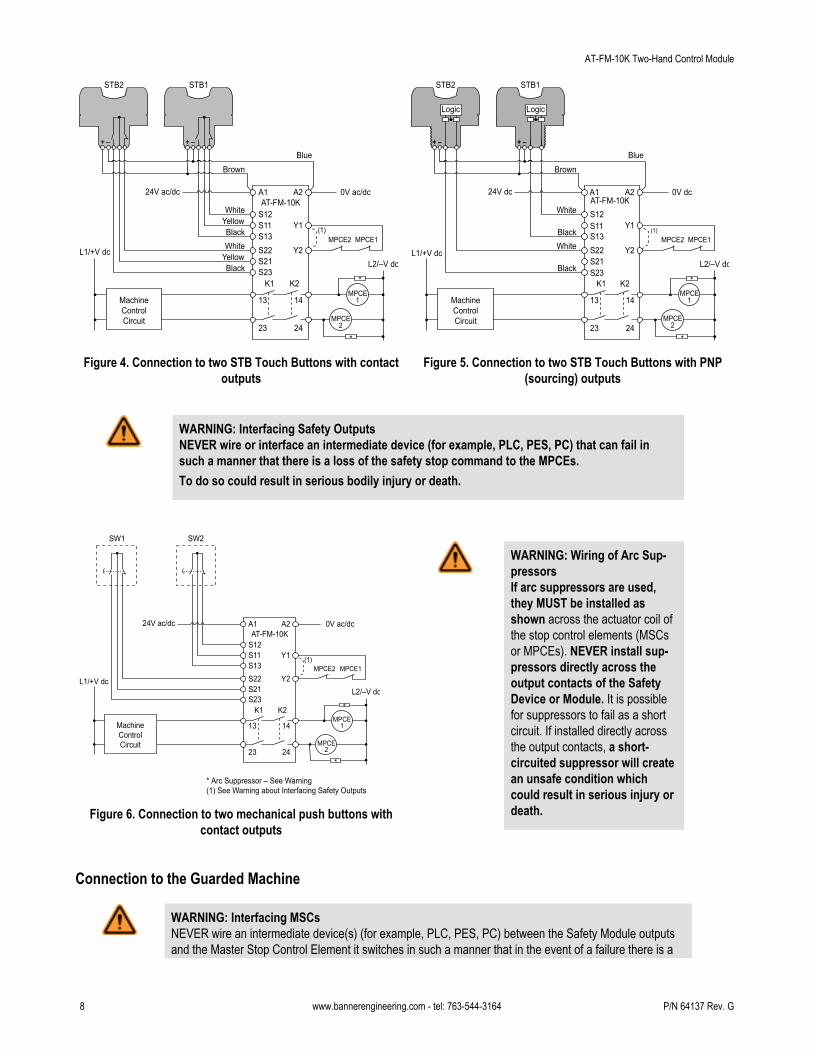
Figure 4. Connection to two STB Touch Buttons with contactoutputs
Logic
STB2
Brown
MPCE2(1)
MPCE1
White
BlackWhite
Black
A2A1
Y1
Y2
24V dc 0V dc
S12S11S13S22S21S23
K1 K2
13
23
14
24
+ –
STB1
AT-FM-10K
+ –
MachineControlCircuit
L1/+V dcL2/–V dc
MPCE1
MPCE2
*
*
Logic
Blue
Figure 5. Connection to two STB Touch Buttons with PNP(sourcing) outputs
WARNING: Interfacing Safety OutputsNEVER wire or interface an intermediate device (for example, PLC, PES, PC) that can fail insuch a manner that there is a loss of the safety stop command to the MPCEs.To do so could result in serious bodily injury or death.
SW1
MPCE2 MPCE1
A2
Y1 (1)
Y2
24V ac/dc 0V ac/dc
S12
A1
S11S13S22S21S23
K1 K2
13
23
14
24
SW2
AT-FM-10K
MachineControlCircuit
L1/+V dcL2/–V dc
MPCE1
MPCE2
*
*
* Arc Suppressor – See Warning(1) See Warning about Interfacing Safety Outputs
Figure 6. Connection to two mechanical push buttons withcontact outputs
WARNING: Wiring of Arc Sup-pressorsIf arc suppressors are used,they MUST be installed asshown across the actuator coil ofthe stop control elements (MSCsor MPCEs). NEVER install sup-pressors directly across theoutput contacts of the SafetyDevice or Module. It is possiblefor suppressors to fail as a shortcircuit. If installed directly acrossthe output contacts, a short-circuited suppressor will createan unsafe condition whichcould result in serious injury ordeath.
Connection to the Guarded Machine
WARNING: Interfacing MSCsNEVER wire an intermediate device(s) (for example, PLC, PES, PC) between the Safety Module outputsand the Master Stop Control Element it switches in such a manner that in the event of a failure there is a
AT-FM-10K Two-Hand Control Module
8 www.bannerengineering.com - tel: 763-544-3164 P/N 64137 Rev. G
loss of the safety stop command, OR in such a manner that the safety function can be suspended, overrid-den, or defeated, unless accomplished with the same or greater degree of safety.Whenever forced-guided, mechanically linked relays are added as intermediate switching devices, a nor-mally closed (N.C.) forced-guided monitor contact from each relay must be added to the series feedbackloop between Safety Module terminals S31 and S32.
The wiring diagrams show a generic connection of the Safety Module’s redundant output contacts to machine primary control elementsMPCE1 and MPCE2. An MPCE is defined as an electrically-powered element, external to the Safety Module, which directly controls themachine’s normal operating cycle so that it is the last (in time) to operate when the cycle is either initiated or arrested. Some older ma-chines offer only one MPCE; for such machines, it may be necessary to add a second MPCE to establish the appropriate level of safetyintegrity (e.g., control reliability).The connection of the safety outputs must be in such a manner that the stop command issued by the Safety Module can not be overrid-den by a device or circuit that is not at the same level of safety integrity. This means that the safety outputs are interfaced on the outputof the machine logic (e.g., PLC or PC). Then, normally, a feedback signal identifies to the machine logic the status of the Safety Moduleand, if possible, the status of the MPCEs.In summary, Control Reliability (OSHA 29CFR1910.217, ANSI B11, and ANSI/RIA R15.06) and Category 3 and 4 (ISO13849-1) require-ments demand that a single failure does not lead to the loss of the safety function, or does not prevent a normal or immediate stop fromoccurring. The failure or the fault must be detected at or before the next demand of safety (e.g., at the beginning or end of a cycle, orwhen a safeguard is actuated). The safety-related function of the machine control then must issue an immediate stop command or pre-vent the next machine cycle or hazardous situation until the failure or fault is corrected.
External Device MonitoringTo satisfy the requirements of Control Reliability (OSHA and ANSI) and Category 3 and 4 of ISO 13849-1 (EN 954-1), the machineprimary control elements (MPCEs) must each offer a normally closed, forced-guided (mechanically linked) monitor contact. Connect onenormally closed monitor contact from each master stop control element in series to Y1 and Y2 (see wiring diagrams).In operation, if one of the switching contacts of either MPCE fails in the energized condition, the associated monitor contact will remainopen. Therefore, it will not be possible to reset the Safety Module. If no MPCE-monitor contacts are monitored, a jumper must be instal-led between terminals Y1 and Y2 (dotted line), as shown in the hookup drawings. It is the user’s responsibility to ensure that anysingle failure will not result in a hazardous condition and will prevent a successive machine cycle.
Overvoltage Category II and III Installations (EN 50178 and IEC 60664-1)The Safety Module is rated for Overvoltage Category III when voltages of 1V to 150V ac/dc are applied to the output relay contacts. It israted for Overvoltage Category II when voltages of 151V to 250V ac/dc are applied to the output relay contacts and no additional precau-tions are taken to attenuate possible overvoltage situations in the supply voltage. The Module can be used in an Overvoltage Category IIIenvironment (with voltages of 151V to 250V ac/dc) if care is taken either to reduce the level of electrical disturbances seen by the Moduleto Overvoltage Category II levels by installing surge suppressor devices (e.g., arc suppressors), or to install extra external insulation inorder to isolate both the Safety Module and the user from the higher voltage levels of a Category III environment.For Overvoltage Category III installations with applied voltages from 151V to 250V ac/dc applied to the output contact(s): theSafety Module may be used under the conditions of a higher overvoltage category where appropriate overvoltage reduction is provided.Appropriate methods include:
• An overvoltage protective device• A transformer with isolated windings• A distribution system with multiple branch circuits (capable of diverting energy of surges)• A capacitance capable of absorbing energy of surges• A resistance or similar damping device capable of dissipating the energy of surges
When switching inductive ac loads, it is good practice to protect the Safety Module outputs by installing appropriately-sized arc suppres-sors. However, if arc suppressors are used, they must be installed across the load being switched (e. g., across the coils of externalsafety relays), and never across the Safety Module’s output contacts (see WARNING, Arc Suppressors).
Initial Checkout ProcedureTo perform the initial checkout, it is necessary to view the red Fault LED and the four green status indicators: Power, Input 1,Input 2 and Output. Proceed with caution around open wiring.
AT-FM-10K Two-Hand Control Module
P/N 64137 Rev. G www.bannerengineering.com - tel: 763-544-3164 9
CAUTION: Disconnect Power Prior to CheckoutBefore performing the initial checkout procedure, make certain all power is disconnected from themachine to be controlled.Dangerous voltages may be present along the Safety Module wiring barriers whenever power to the ma-chine control elements is ON. Exercise extreme caution whenever machine control power is or maybe present. Always disconnect power to the machine control elements before opening the enclo-sure housing of the Safety Module.
WARNING: EDM MonitoringIf the System is configured for “No Monitoring,” it is the user’s responsibility to ensure that thisdoes not create a hazardous situation.
1. Verify that the two actuating devices are properly connected to the Module.2. Apply power to the Safety Module and to the actuating devices, if applicable.3. Verify that only the Power indicator is ON. If any of the other Safety Module indicators are ON, disconnect the power to the Safety
Module and check all wiring. Do not continue this checkout procedure until the cause of the problem is corrected.4. Activate both hand controls simultaneously (within 0.5 seconds), and hold them engaged. Input 1 and Input 2 indicators should
come ON. Release both hand controls simultaneously. Output indicator should go OFF.5. Again, activate the two hand controls simultaneously, and hold them engaged. Input 1, Input 2, and Output indicators should come
ON. Release one hand control, while holding the other engaged. One of the indicators should remain ON. The Output indicatorshould go OFF. Re-activate the hand control which was just released. The Output indicator should remain OFF. Release both handcontrols. Input 1 and Input 2 indicators should then be OFF.
6. Activate only one hand control and hold it engaged. Input 1 (Input 2) indicator should come ON. After more than 1/2 second, acti-vate the second hand control. Input 1 and 2 indicators should remain ON, while Output indicator remains OFF.
7. Remove power from the Safety Module and disconnect the monitor contact feedback loop at terminals Y1 and/or Y2. Re-applypower to the Safety Module. Activate both hand controls simultaneously. Output indicator LED should remain OFF.
If the Safety Module passes all of these tests, reconnect the output wires at terminals 13/14 and 23/24. Do not attempt to use theSafety Module until all of the tests are passed.
Daily Checkout ProcedureTo be Performed at every Power-up, Shift Change, and Tooling/Machine Setup ChangeThe daily checkout must be performed by a Designated Person, appointed and identified in writing by the employer, or by aQualified Person (see below).
WARNING: EDM MonitoringIf the System is configured for “No Monitoring,” it is the user’s responsibility to ensure that thisdoes not create a hazardous situation.
1. Verify that all point-of-operation guards are in place and operating properly.2. Verify that the two actuating devices must be simultaneously engaged to actuate the machine.3. For single-cycle machines: Verify that maintained engagement of the two actuating devices results in only one machine cycle.
For part-revolution clutch machinery: Verify that release of either actuating device results in the immediate arrest of the ma-chine motion.
4. Verify that the distance from each actuating device to the closest hazard point is not less than the calculated safety distance.
Semi-Annual Checkout ProcedureTo be Performed at Six-Month IntervalsThis semi-annual checkout must be performed by a Qualified Person (a person who, by possession of a recognized degree orcertificate of professional training, or who, by extensive knowledge, training, and experience, has successfully demonstrated
AT-FM-10K Two-Hand Control Module
10 www.bannerengineering.com - tel: 763-544-3164 P/N 64137 Rev. G
the ability to solve problems relating to the installation, maintenance and use of the Safety System). Keep a copy of the testresults on or near the machine.
WARNING: EDM MonitoringIf the System is configured for “No Monitoring,” it is the user’s responsibility to ensure that thisdoes not create a hazardous situation.
1. Perform the daily checkout procedure.2. Perform the initial checkout procedure.3. Calculate the separation distance, and verify that the actuating devices are far enough away from the nearest hazard point. Relo-
cate the actuating devices, if necessary.4. Verify that the actuating devices are positioned to require the use of both hands for operation, and are protected from false or
inadvertent operation.5. Inspect the machine controls and the connections to the Safety Module to ensure that wiring is correct and that no modifications
have been made which could adversely affect the System.
RepairsNOTE: Do not attempt any repairs to the Safety Module. It contains no field-replaceable components. Return it to the factory for warrantyrepair or replacement.
CAUTION: Abuse of Module After FailureIf an internal fault has occurred and the Module will not reset, do not tap, strike, or otherwise attempt tocorrect the fault by a physical impact to the housing. An internal relay may have failed in such a man-ner that its replacement is required.If the Module is not immediately replaced or repaired, multiple simultaneous failures may accumu-late such that the safety function can not be guaranteed.
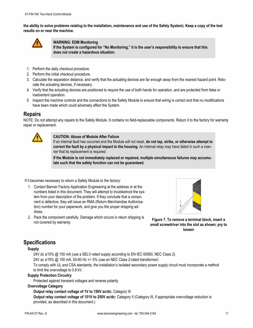
If it becomes necessary to return a Safety Module to the factory:1. Contact Banner Factory Application Engineering at the address or at the
numbers listed in this document. They will attempt to troubleshoot the sys-tem from your description of the problem. If they conclude that a compo-nent is defective, they will issue an RMA (Return Merchandise Authoriza-tion) number for your paperwork, and give you the proper shipping ad-dress.
2. Pack the component carefully. Damage which occurs in return shipping isnot covered by warranty. Figure 7. To remove a terminal block, insert a
small screwdriver into the slot as shown; pry toloosen
SpecificationsSupply
24V dc ±15% @ 150 mA (use a SELV-rated supply according to EN IEC 60950, NEC Class 2)24V ac ±15% @ 150 mA, 50-60 Hz +/- 5% (use an NEC Class 2-rated transformer)To comply with UL and CSA standards, the installation’s isolated secondary power supply circuit must incorporate a methodto limit the overvoltage to 0.8 kV.
Supply Protection CircuitryProtected against transient voltages and reverse polarity
Overvoltage CategoryOutput relay contact voltage of 1V to 150V ac/dc: Category IIIOutput relay contact voltage of 151V to 250V ac/dc: Category II (Category III, if appropriate overvoltage reduction isprovided, as described in this document.)
AT-FM-10K Two-Hand Control Module
P/N 64137 Rev. G www.bannerengineering.com - tel: 763-544-3164 11
Pollution Degree2
Output ConfigurationEach normally open output channel is a series connection of contacts from two forced-guided (mechanically linked) relays,K1-K2.Contacts: AgNi, 5 µm gold-platedLow Current Rating: The 5 µm gold-plated contacts allow the switching of low current/low voltage. In these low-powerapplications, multiple contacts can also be switched in series (e.g., “dry switching”). To preserve the gold plating on thecontacts, do not exceed the following max. values at any time:
Min. voltage: 1V ac/dc Max. voltage: 60V
Min. current: 5 mA ac/dc Max. current: 300 mA
Min. power: 5 mW (5 mVA) Max. power: 7 W (7 VA)
High Current Rating: If higher loads must be switched through one or more of the contacts, the minimum and maximumvalues of the contact(s) changes to:
Minimum: Maximum:
Voltage: 15V ac/dc 250V ac / 24V dc, 6 A resistive
Current: 30 mA ac/dc ——
Power: 0.45 W (0.45 VA) ——
Voltage: 15V ac/dc 250V ac / 24V dc, 6 A resistive
Current: 30 mA ac/dc IEC 60947-5-1; AC15: 230V ac, 3 A;DC-13: 24V dc, 2 A
Power: 0.45 W (0.45 VA) ——
Mechanical life: 20,000,000 operationsElectrical life (switching cycles of the output contacts, resistive load): 150,000 cycles @ 900 VA; 1,000,000 cycles @250 VA; 2,000,000 cycles @ 150 VA; 5,000,000 cycles @ 100 VA
Output Response Time35 milliseconds maximum
Input RequirementsOutputs from actuating devices must each be capable of switching 25 mA @ 24V dc (nominal).
Simultaneity Monitoring Period≤ 500 milliseconds
Status Indicators4 green LED indicators: Power ON, Input 1 energized, Input 2 energized, Output1 red LED indicator: Fault
ConstructionPolycarbonate housing. Rated IEC IP20
MountingMounts to standard 35 mm DIN rail track. Safety Module must be installed inside an enclosure rated NEMA 3 (IEC IP54), orbetter.
Vibration Resistance10 to 55 Hz @ 0.35 mm displacement per IEC 60068-2-6
Operating ConditionsTemperature: 0° to +50°C (+32° to 122°F) See "Heat Dissipation Considerations."Maximum Relative Humidity: 90% @ +50°C (non-condensing)
DimensionsSee following figure.
AT-FM-10K Two-Hand Control Module
12 www.bannerengineering.com - tel: 763-544-3164 P/N 64137 Rev. G
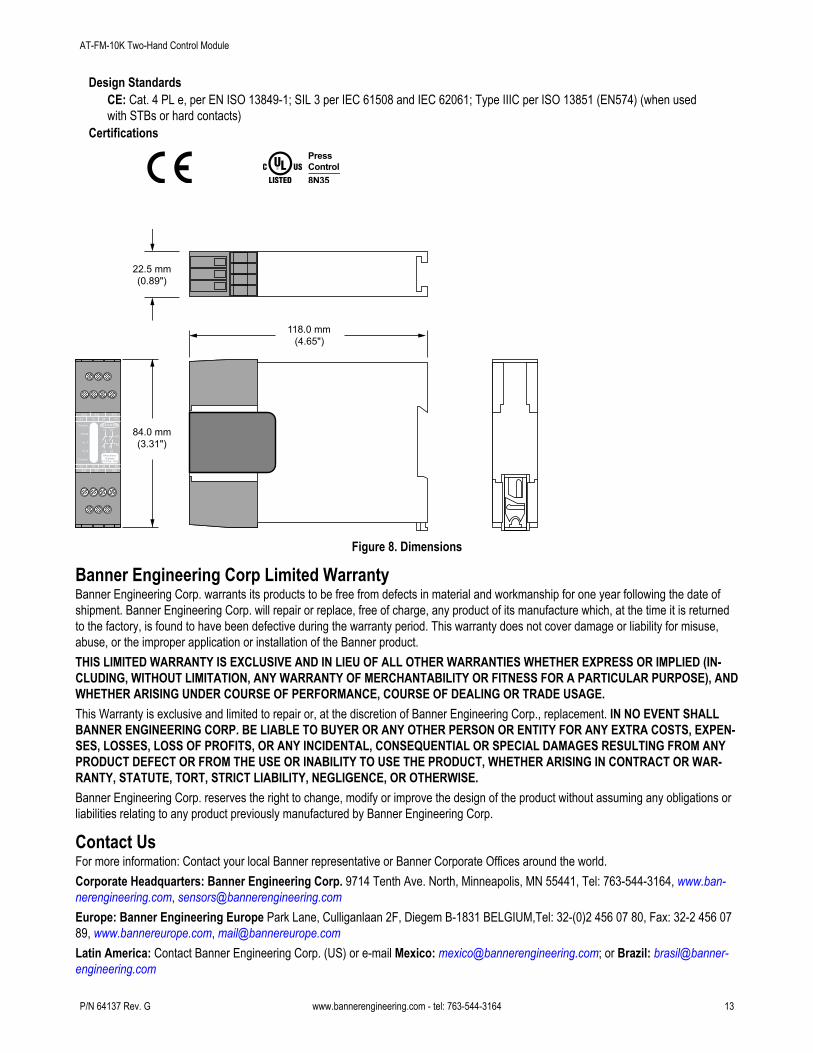
Design StandardsCE: Cat. 4 PL e, per EN ISO 13849-1; SIL 3 per IEC 61508 and IEC 62061; Type IIIC per ISO 13851 (EN574) (when usedwith STBs or hard contacts)
Certifications
S12A1
S11 S13
S23 S21 S22
13 23 Y1
Y2 14 24 A2
K1
K2
14 24
13 23
MachineSafety
AT-FM-10K
Power
Fault
In 1
In 2
Output
118.0 mm(4.65")
84.0 mm(3.31")
22.5 mm(0.89")
Figure 8. Dimensions
Banner Engineering Corp Limited WarrantyBanner Engineering Corp. warrants its products to be free from defects in material and workmanship for one year following the date ofshipment. Banner Engineering Corp. will repair or replace, free of charge, any product of its manufacture which, at the time it is returnedto the factory, is found to have been defective during the warranty period. This warranty does not cover damage or liability for misuse,abuse, or the improper application or installation of the Banner product.THIS LIMITED WARRANTY IS EXCLUSIVE AND IN LIEU OF ALL OTHER WARRANTIES WHETHER EXPRESS OR IMPLIED (IN-CLUDING, WITHOUT LIMITATION, ANY WARRANTY OF MERCHANTABILITY OR FITNESS FOR A PARTICULAR PURPOSE), ANDWHETHER ARISING UNDER COURSE OF PERFORMANCE, COURSE OF DEALING OR TRADE USAGE.This Warranty is exclusive and limited to repair or, at the discretion of Banner Engineering Corp., replacement. IN NO EVENT SHALLBANNER ENGINEERING CORP. BE LIABLE TO BUYER OR ANY OTHER PERSON OR ENTITY FOR ANY EXTRA COSTS, EXPEN-SES, LOSSES, LOSS OF PROFITS, OR ANY INCIDENTAL, CONSEQUENTIAL OR SPECIAL DAMAGES RESULTING FROM ANYPRODUCT DEFECT OR FROM THE USE OR INABILITY TO USE THE PRODUCT, WHETHER ARISING IN CONTRACT OR WAR-RANTY, STATUTE, TORT, STRICT LIABILITY, NEGLIGENCE, OR OTHERWISE.Banner Engineering Corp. reserves the right to change, modify or improve the design of the product without assuming any obligations orliabilities relating to any product previously manufactured by Banner Engineering Corp.
Contact UsFor more information: Contact your local Banner representative or Banner Corporate Offices around the world.Corporate Headquarters: Banner Engineering Corp. 9714 Tenth Ave. North, Minneapolis, MN 55441, Tel: 763-544-3164, www.ban-nerengineering.com, [email protected]: Banner Engineering Europe Park Lane, Culliganlaan 2F, Diegem B-1831 BELGIUM,Tel: 32-(0)2 456 07 80, Fax: 32-2 456 0789, www.bannereurope.com, [email protected] America: Contact Banner Engineering Corp. (US) or e-mail Mexico: [email protected]; or Brazil: [email protected]
AT-FM-10K Two-Hand Control Module
P/N 64137 Rev. G www.bannerengineering.com - tel: 763-544-3164 13
Asia:Banner Engineering China Shanghai Rep Office Xinlian Scientific Research Building, Level 12, Building 2, 1535 Hongmei Road,Shanghai 200030 CHINA, Tel: 86-21-33986888, Fax: 86-21-33986999, www.bannerengineering.com.cn, [email protected] Engineering Japan Cent-Urban Building 305 3-23-15, Nishi-Nakajima Yodogawa-Ku, Osaka 532-0011 JAPAN, Tel: 81-(0)6-6309-0411, Fax: 81-6-6309-0416, www.bannerengineering.co.jp, [email protected] Engineering Int’l Incorporated Taiwan Rep. Office 8F-2, No. 308, Sec. 1, Neihu Rd. Taipei, Taiwan 114 Tel: +886 (0)2 87519966, Fax: +886 2 8751 2966, www.bannerengineering.com.tw, [email protected] Engineering India Pune Head Quarters Office, No. 1001 Sai Capital, Opp. ICC Senapati Bapat Road, Pune 411016 INDIA, Tel:91-(0)20-66405624, Fax: 91-(0)20-66405623, www.bannerengineering.co.in, [email protected]
AT-FM-10K Two-Hand Control Module
www.bannerengineering.com - tel: 763-544-3164