Embed Size (px)
Citation preview
.
1 NASA i TP I 126% i c.1
1
NASA Technical Paper 1268
I
Application of Shock
A
Tubes . I
to Transonic Airfoil Testing at High Reynolds Numbers
William J. Cook, Michael J. Chaney, Leroy L. Presley, and Gary T. Chapman
F n m z E
NOVEMBER 1978
https://ntrs.nasa.gov/search.jsp?R=19790003842 2018-07-11T13:20:00+00:00Z
TECH LIBRARY KAFB, NM
Ob3449b
NASA Technical Paper 1268
Application of Shock Tubes to Transonic Airfoil Testing at High Reynolds Numbers
William J. Cook and Michael J. Chaney Iowa State University Ames, Iowa
Leroy L. Presley and Gary T. Chapman Ames Research Center Moffett Field, Ca lifornia
NASA National Aeronautics and Space Administration
Scientific and Technical Information Office
1978

W . *
TABLE O F CONTENTS
NOMENCLATURE . . . . . . . . . . . . . . . . . . . . . . . . . . . SUMMARY . . . . . . . . . . . . . . . . . . . . . . . . . . . . . INTRODUCTION . . . . . . . . . . . . . . . . . . . . . . . . . . SHOCK-TUBE PERFORMANCE ANALYSIS FOR H I G H REYNOLDS NUMBER
TRANSONIC T E S T I N G . . . . . . . . . . . . . . . . . . . . . . EXPERIMENTAL STUDY . . . . . . . . . . . . . . . . . . . . . . . .
Tes t ing T i m e . . . . . . . . . . . . . . . . . . . . . . . . W a l l B o u n d a r y Layers . . . . . . . . . . . . . . . . . . . . Inf luence of W a l l s on F l o w F i e l d . . . . . . . . . . . . . . A i r f o i l Pressure M e a s u r e m e n t s . . . . . . . . . . . . . . . .
RESULTS . . . . . . . . . . . . . . . . . . . . . . . . . . . . . Schl ie ren Photography . . . . . . . . . . . . . . . . . . . . P r e s s u r e R e s u l t s . . . . . . . . . . . . . . . . . . . . . .
ZONCLUDING REMARKS . . . . . . . . . . . . . . . . . . . . . . . . "J'PENDIX A . . . . . . . . . . . . . . . . . . . . . . . . . . . . V P E N D I X B . . . . . . . . . . . . . . . . . . . . . . . . . . . . tEFERENCES . . . . . . . . . . . . . . . . . . . . . . . . . . . .
Page
V
3
9 9 11
16
17
25
28
iii
NOMENCLATURE
a speed of sound
C P
P C*
e
M
ovs
P
AP
4
Ree
ReU
RU
T
TCF
t
ti t'
u2
2
2 m
p r e s s u r e c o e f f i c i e n t , e q u a t i o n (5)
p r e s s u r e c o e f f i c i e n t a t M = 1
a i r f o i l chord l e n g t h
Mach number
u2 - a2 TI ..,
S shock Mach number, - a1
molecular weight
o s c i l l o s c o p e ve r t i ca l s e n s i t i v i t y , e q u a t i o n ( 6 )
s t a t i c p r e s s u r e
p r e s s u r e change i n d i c a t e d by p r e s s u r e t r a n s d u c e r
dynamic p r e s s u r e , -
chord Reynolds number, ~
Re u n i t Reynolds number -
p 2u;
2 u2ep2
p2
X
u n i v e r s a l g a s c o n s t a n t
a b s o l u t e tempera ture
t r a n s d u c e r c a l i b r a t i o n f a c t o r , e q u a t i o n (6)
t i m e
i d e a l r e g i o n 2 t es t t i m e
t i m e , t' = 0 when pr imary shock wave arrives a t a i r f o i l l e a d i n g edge
pr imary shock w a v e v e l o c i t y
tes t g a s v e l o c i t y behind pr imary shock wave measured i n r e f e r e n c e frame f i x e d t o shock t u b e w a l l
d i s t a n c e
model d i s t a n c e from diaphragm, f i g u r e 1
V
v e r t i c a l change i n trace on p r e s s u r e t r a n s d u c e r r e c o r d , e q u a t i o n (6 )
Y g a s s p e c i f i c h e a t r a t i o
6 v e l o c i t y boundary-layer t h i c k n e s s
u v i s c o s i t y c o e f f i c i e n t
P d e n s i t y
X mole f r a c t i o n of argon
S u b s c r i p t s :
e based on a i r f o i l chord l e n g t h
ij
1 tes t g a s ahead of pr imary shock wave
2 t es t g a s behind pr imary shock wave ( s e e u, and M, a l s o )
4 d r i v e r g a s
m u n d i s t u r b e d f low remote from model ( r e g i o n 2 i n p r e s e n t s t u d y )
vi
I
APPLICATION OF SHOCK TUBES TO TRANSONIC AIRFOIL TESTING
AT HIGH REYNOLDS NUMBERS
W i l l i a m J. Cook* and Michael J. Chaney*
Iowa S t a t e U n i v e r s i t y , Ames, Iowa
Leroy L. P r e s l e y and Gary T. Chapman
Ames Research Center
SUMMARY
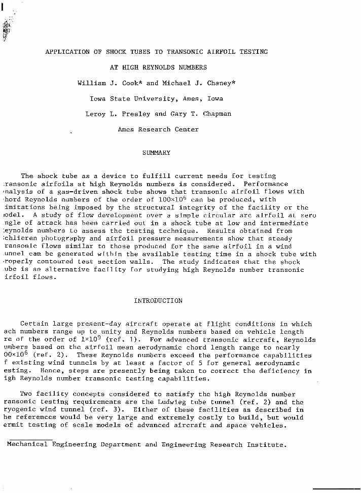
The shock t u b e as a d e v i c e t o f u l f i l l c u r r e n t needs f o r t e s t i n g r a n s o n i c a i r f o i l s a t h i g h Reynolds numbers is c o n s i d e r e d . Performance
: n a l y s i s of a gas-dr iven shock t u b e shows t h a t t r a n s o n i c a i r f o i l f lows w i t h .hard Reynolds numbers of t h e o r d e r of 1 0 0 ~ 1 0 ~ can b e produced, w i t h i m i t a t i o n s b e i n g imposed by t h e s t r u c t u r a l i n t e g r i t y of t h e f a c i l i t y o r t h e iodel. A s t u d y of f low development over a s imple c i r c u l a r a rc a i r f o i l a t z e r o n g l e of a t t a c k h a s been c a r r i e d o u t i n a shock t u b e a t low and i n t e r m e d i a t e :eynolds numbers t o assess t h e t e s t i n g technique . R e s u l t s o b t a i n e d from i c h l i e r e n photography and a i r f o i l p r e s s u r e measurements show t h a t s t e a d y r a n s o n i c f lows s i m i l a r t o t h o s e produced f o r t h e s a m e a i r f o i l i n a wind unnel can b e genera ted w i t h i n t h e a v a i l a b l e t e s t i n g t i m e i n a shock t u b e w i t h . r o p e r l y contoured tes t s e c t i o n w a l l s . The s t u d y i n d i c a t e s t h a t t h e shock ube i s an a l t e r n a t i v e f a c i l i t y f o r s t u d y i n g h i g h Reynolds number t r a n s o n i c i r f o i l f lows.
INTRODUCTION
C e r t a i n l a r g e present-day a i r c r a f t o p e r a t e a t f l i g h t c o n d i t i o n s i n which ach numbers range up t o u n i t y and Reynolds numbers based on v e h i c l e l e n g t h re of t h e o r d e r of lx109 ( r e f . 1). umbers based on t h e a i r f o i l mean aerodynamic chord l e n g t h r a n g e t o n e a r l y 0 0 ~ 1 0 ~ ( r e f . 2 ) . These Reynolds numbers exceed t h e performance c a p a b i l i t i e s f e x i s t i n g wind t u n n e l s by a t least a f a c t o r of 5 f o r g e n e r a l aerodynamic e s t i n g . Hence, s t e p s are p r e s e n t l y b e i n g t a k e n t o c o r r e c t t h e d e f i c i e n c y i n i g h Reynolds number t r a n s o n i c t e s t i n g c a p a b i l i t i e s .
For advanced t r a n s o n i c a i r c r a f t , Reynolds
Two f a c i l i t y concepts c o n s i d e r e d t o s a t i s f y t h e h i g h Reynolds number r a n s o n i c t e s t i n g requi rements are t h e Ludwieg t u b e t u n n e l ( r e f . 2 ) and t h e r y o g e n i c wind t u n n e l ( r e f . 3 ) . E i t h e r of t h e s e f a c i l i t i e s as d e s c r i b e d i n h e r e f e r e n c e s would b e v e r y l a r g e and ex t remely c o s t l y to b u i l d , b u t would e r m i t t e s t i n g of scale models of advanced a i r c r a f t and s p a c e v e h i c l e s .
Mechanical Engineer ing Department and Engineer ing Research I n s t i t u t e .
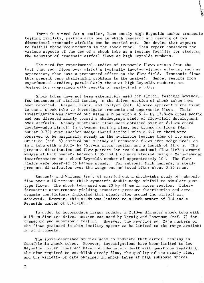
There is a need f o smaller, less c o s t l y h i g h Reynolds number t r a n s o n i c t e s t i n g f a c i l i t y , p a r t i c u l a r l y one i n which r e s e a r c h and t e s t i n g of two d imens iona l t r a n s o n i c a i r f o i l s can b e c a r r i e d o u t . One d e v i c e t h a t a p p e a r s t o f u l f i l l t h e s e r e q u i r e m e n t s is t h e shock tube . T h i s r e p o r t c o n s i d e r s t h e v a r i o u s a s p e c t s of t h e u s e of a shock t u b e as a t e s t i n g f a c i l i t y f o r s t u d y i n g t h e behavior of t r a n s o n i c a i r f o i l f lows a t h i g h Reynolds numbers.
The need f o r exper imenta l s t u d i e s of t r a n s o n i c f lows ar ises from t h e f a c t t h a t such f lows over a i r f o i l s t y p i c a l l y i n v o l v e v i s c o u s e f f e c t s , such as s e p a r a t i o n , t h a t have a pronounced e f f e c t on t h e f low f i e l d . Transonic f lows t h u s p r e s e n t v e r y c h a l l e n g i n g problems t o t h e a n a l y s t . Hence; r e s u l t s from e x p e r i m e n t a l s t u d i e s , p a r t i c u l a r l y t h o s e a t h i g h Reynolds numbers, are d e s i r e d f o r comparison w i t h r e s u l t s of a n a l y t i c a l s t u d i e s .
Shock t u b e s have n o t been e x t e n s i v e l y used f o r a i r f o i l t e s t i n g ; however, .
few i n s t a n c e s of a i r f o i l t e s t i n g i n t h e d r i v e n s e c t i o n of shock t u b e s have been r e p o r t e d . Geiger , Mautz, and Hol lyer ( r e f . 4) w e r e a p p a r e n t l y t h e f i r s t t o u s e a shock t u b e t o i n v e s t i g a t e t r a n s o n i c and s u p e r s o n i c f lows . T h e i r i n v e s t i g a t i o n w a s c a r r i e d o u t u s i n g a t u b e w i t h a 5.1- by 17.8-cm c r o s s s e c t i o and w a s d i r e c t e d mainly toward a shadowgraph s t u d y of f l o w - f i e l d development o v e r a i r f o i l s . Steady s u p e r s o n i c f lows w e r e o b t a i n e d o v e r a n 8 . 1 - c m chord double-wedge a i r f o i l i n 0.4-msec t e s t i n g t i m e , b u t t r a n s o n i c f lows (Mach number 0.79) o v e r a n o t h e r wedge-shaped a i r f o i l w i t h a 6.4-cm chord w e r e observed t o b e m a r g i n a l l y s t e a d y i n t h e a v a i l a b l e t e s t i n g t i m e of 1 . 5 msec. G r i f f i t h ( r e f . 5) c a r r i e d o u t a s t u d y o f t r a n s o n i c f lows o v e r wedge p r o f i l e s i n a t u b e w i t h a 10.2- by 45.7-cm c r o s s s e c t i o n and a l e n g t h of 11.6 m. The p r e s s u r e d i s t r i b u t i o n and f low p a t t e r n f o r two d imens iona l f low f i e l d s around wedges a t Mach numbers between 0.85 and 1 . 8 0 w e r e s t u d i e d u s i n g a Mach-Zehnder i n t e r f e r o m e t e r a t a chord Reynolds number of approximate ly l o 5 . f i e l d s w e r e observed t o become s t e a d y . For s u b s o n i c Mach numbers, a s t e a d y p r e s s u r e d i s t r i b u t i o n over t h e wedge w a s ach ieved a f t e r about 0 .35 m s e c .
The f low
Ruetenik and Whitmer ( r e f . 6) c a r r i e d o u t a shock-tube s t u d y of s u b s o n i c f low over a 1 0 p e r c e n t t h i c k symmetric double-wedge a i r f o i l t o s i m u l a t e gus t - t y p e f lows . The shock t u b e used w a s 20 by 61 c m i n c r o s s s e c t i o n . I n t e r - f e r o m e t r i c measurements y i e l d i n g t r a n s i e n t p r e s s u r e d i s t r i b u t i o n and aero- dynamic c o e f f i c i e n t s i n d i c a t e d t h a t s t e a d y f l o w around t h e a i r f o i l w a s ach ieved . However, t h i s s t u d y w a s l i m i t e d t o a Mach number of 0 .4 and a Reynolds number of 0 . 6 5 ~ 1 0 ~ .
I n o r d e r t o accommodate l a r g e r models, a 2.13-m diameter shock t u b e w i t h a 15-cm diameter d r i v e r s e c t i o n w a s used by Varwig and Rosenman ( r e f . 7) f o r t r a n s o n i c and s u p e r s o n i c t e s t i n g . However, t h e Reynolds and Mach numbers of t h e f lows produced i n t h i s f a c i l i t y appear t o be l i m i t e d t o t h e range a v a i l a b l i n wind t u n n e l s .
The above-described s t u d i e s seem t o i n d i c a t e t h a t a i r f o i l t e s t i n g i s f e a s i b l e i n shock t u b e s . However, i n v e s t i g a t i o n s have been l i m i t e d t o low Reynolds number f lows and have n o t a d e q u a t e l y d e a l t w i t h q u e s t i o n s r e g a r d i n g t h e t i m e r e q u i r e d t o e s t a b l i s h s t e a d y f low, t h e q u a l i t y o f t h e s t e a d y f low, and t h e v a l i d i t y of d a t a o b t a i n e d i n shock t u b e s a t h i g h s u b s o n i c speeds
2
re lat ive t o d a t a o b t a i n e d i n c o n v e n t i o n a l t r a n s o n i c wind t u n n e l s . Hence, t h e i r e s e n t s t u d y w a s under taken t o i n v e s t i g a t e i n d e t a i l t h e p r a c t i c a l i t y o f Zarrying o u t h i g h Reynolds number t r a n s o n i c a i r f o i l t e s t i n g i n shock t u b e s .
SHOCK-TUBE PERFORMANCE ANALYSIS FOR HIGH REYNOLDS NUMBER TRANSONIC TESTING
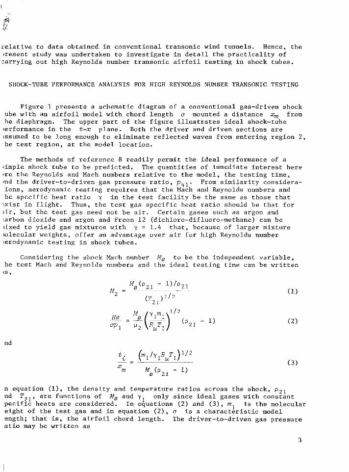
F i g u r e 1 p r e s e n t s a schemat ic diagram of a c o n v e n t i o n a l gas-dr iven shock ube w i t h a n a i r f o i l model w i t h chord l e n g t h e mounted a d i s t a n c e xm from h e diaphragm. The upper p a r t o f t h e f i g u r e i l l u s t r a t e s i d e a l shock-tube
ierformance i n t h e t-x p l a n e . Both t h e d r i v e r and d r i v e n s e c t i o n s are issumed t o b e l o n g enough t o e l i m i n a t e r e f l e c t e d waves from e n t e r i n g r e g i o n 2 , h e t es t r e g i o n , a t t h e model l o c a t i o n .
The methods of r e f e r e n c e 8 r e a d i l y permi t t h e i d e a l performance of a :imple shock t u b e t o b e p r e d i c t e d . The q u a n t i t i e s of immediate i n t e r e s t h e r e :re t h e Reynolds and Mach numbers r e l a t ive t o t h e model, t h e t e s t i n g t i m e , :nd t h e d r i v e r - t o - d r i v e n g a s p r e s s u r e r a t i o , p41. From s i m i l a r i t y cons idera- i o n s , aerodynamic t e s t i n g r e q u i r e s t h a t t h e Mach and Reynolds numbers and h e s p e c i f i c h e a t r a t i o y i n t h e tes t f a c i l i t y b e t h e same as t h o s e t h a t - x i s t i n f l i g h t . Thus, t h e test g a s s p e c i f i c h e a t r a t i o should b e t h a t f o r :ir, b u t t h e t es t g a s need n o t b e a i r . C e r t a i n g a s e s such as argon and :arbon d i o x i d e and argon and Freon 1 2 (dichloro-difluoro-methane) can b e i ixed t o y i e l d gas m i x t u r e s w i t h y = 1 . 4 t h a t , because of l a r g e r m i x t u r e i o l e c u l a r w e i g h t s , o f f e r an advantage o v e r a i r f o r h i g h Reynolds number ierodynamic t e s t i n g i n shock t u b e s .
Cons ider ing t h e shock Mach number Ms t o b e t h e independent v a r i a b l e , h e t e s t Mach and Reynolds numbers and t h e i d e a l t e s t i n g t i m e can be w r i t t e n is ,
Ms(P21 - W P 2 1 M, =
nd
Y
- 1 ) A-
m Ms(% ( 3 )
n e q u a t i o n (l), t h e d e n s i t y and tempera ture r a t i o s a c r o s s t h e shock, p Z 1 nd TZl, are f u n c t i o n s of M, and y o n l y s i n c e i d e a l g a s e s w i t h c o n s t a n t
1 p e c i f i c h e a t s are c o n s i d e r e d . e i g h t of t h e t es t g a s and i n e q u a t i o n ( 2 ) , e i s a c h a r a c t e r i s t i c model ength ; t h a t is, t h e a i r f o i l chord l e n g t h . The d r i v e r - t o - d r i v e n g a s p r e s s u r e a t i o may b e w r i t t e n as
I n e q u a t i o n s ( 2 ) and (3), m l i s t h e molecular
3
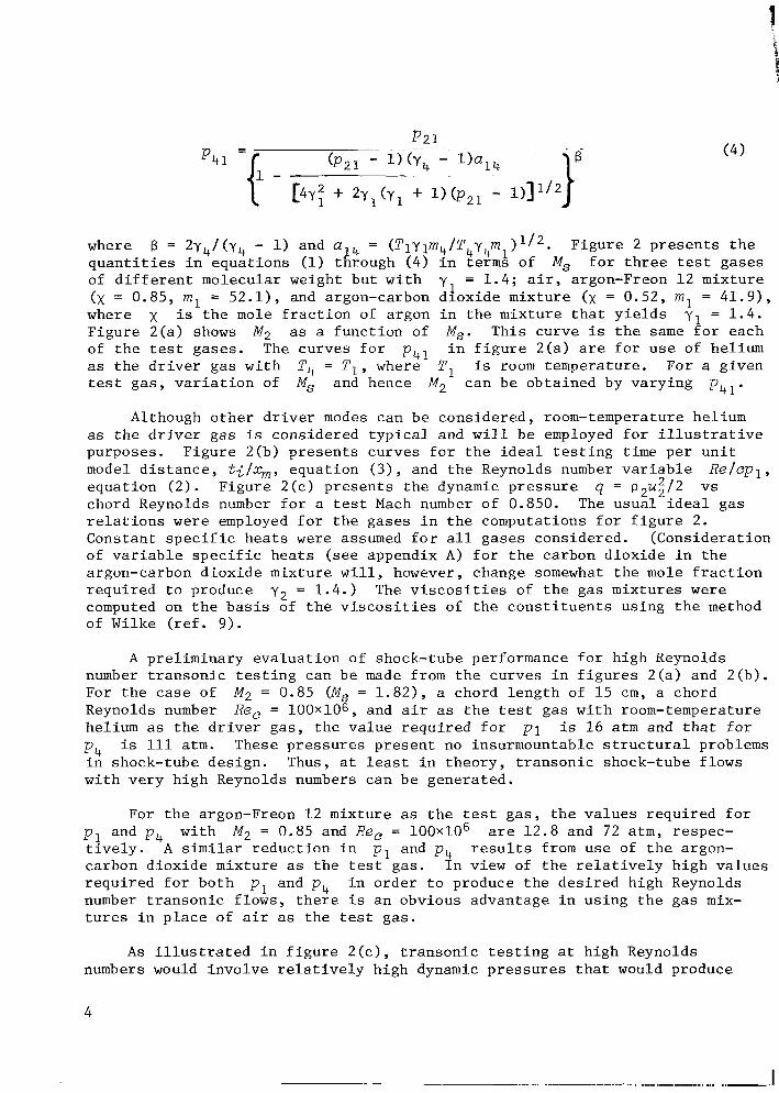
p 2 1
where q u a n t i t i e s i n e q u a t i o n s (1) through (4) i n t e r m s of M, f o r t h r e e test g a s e s of d i f f e r e n t molecular weight b u t w i t h y = 1 . 4 ; a i r , argon-Freon 12 m i x t u r e (x = 0.85, m, = 5 2 . 1 ) , and argon-carbon d i o x i d e m i x t u r e (x = 0.52, m l = 41.9) , where x i s t h e mole f r a c t i o n of argon i n t h e m i x t u r e t h a t y i e l d s y1 = 1.4 . F i g u r e 2 ( a ) shows M2 as a f u n c t i o n of M,. T h i s c u r v e is t h e s a m e f o r each of t h e t es t g a s e s . The c u r v e s f o r p41 i n f i g u r e 2 ( a ) are f o r u s e of hel ium as t h e d r i v e r g a s w i t h P, = P I , where T , i s room tempera ture . For a g i v e n t e s t g a s , v a r i a t i o n of M, and hence M, can b e o b t a i n e d by v a r y i n g p,, .
f3 = 2y4/ (y4 - 1) and a 1 4 = ( T 1 ~ l m ~ / T ~ ~ ~ m ~ ) F i g u r e 2 p r e s e n t s t h e
1
Although o t h e r d r i v e r modes can b e c o n s i d e r e d , room-temperature hel ium as t h e d r i v e r g a s i s cons idered t y p i c a l and w i l l b e employed f o r i l l u s t r a t i v e purposes . F i g u r e 2(b) p r e s e n t s c u r v e s f o r t h e i d e a l t e s t i n g t i m e p e r u n i t model d i s t a n c e , ti/xm, e q u a t i o n ( 3 ) , and t h e Reynolds number v a r i a b l e e q u a t i o n ( 2 ) . F i g u r e 2 ( c ) p r e s e n t s t h e dynamic p r e s s u r e q = p,ug/2 vs chord Reynolds number f o r a test Mach number of 0.850. The u s u a l i d e a l g a s r e l a t i o n s w e r e employed f o r t h e g a s e s i n t h e computat ions f o r f i g u r e 2. Cons tan t s p e c i f i c h e a t s w e r e assumed f o r a l l g a s e s cons idered . ( C o n s i d e r a t i o n of v a r i a b l e s p e c i f i c h e a t s ( s e e appendix A) f o r t h e carbon d i o x i d e i n t h e argon-carbon d i o x i d e m i x t u r e w i l l , however, change somewhat t h e mole f r a c t i o n r e q u i r e d t o produce The v i s c o s i t i e s of t h e g a s m i x t u r e s w e r e computed on t h e b a s i s of t h e v i s c o s i t i e s of t h e c o n s t i t u e n t s u s i n g t h e method of Wilke ( r e f . 9 ) .
R e / e p l ,
y2 = 1.4.)
A p r e l i m i n a r y e v a l u a t i o n o f shock-tube performance f o r h i g h Reynolds number t r a n s o n i c t e s t i n g can b e made from t h e c u r v e s i n f i g u r e s 2 ( a ) and 2 ( b ) . For t h e case of Reynolds number hel ium as t h e d r i v e r g a s , t h e v a l u e r e q u i r e d f o r p 1 is 16 a t m and t h a t f o r p4 is 111 a t m . i n shock-tube d e s i g n . Thus, a t l ea s t i n t h e o r y , t r a n s o n i c shock-tube f lows w i t h v e r y h i g h Reynolds numbers can b e g e n e r a t e d .
M2 = 0.85 (M, = 1 . 8 2 ) , a chord l e n g t h of 1 5 c m , a chord R e , = 100x106, and a i r as t h e t es t g a s w i t h room-temperature
These p r e s s u r e s p r e s e n t no insurmountable s t r u c t u r a l problems
For t h e argon-Freon 1 2 m i x t u r e as t h e t e s t g a s , t h e v a l u e s r e q u i r e d f o r p1 and p , are 1 2 . 8 and 72 a t m , respec- t i v e l y . A s i m i l a r r e d u c t i o n i n p , and p , r e s u l t s from u s e of t h e argon- carbon d i o x i d e m i x t u r e as t h e test gas . I n v i e w of t h e r e l a t i v e l y h i g h v a l u e s r e q u i r e d f o r b o t h i n o r d e r t o produce t h e d e s i r e d h i g h Reynolds number t r a n s o n i c f lows , t h e r e i s a n obvious advantage i n u s i n g t h e g a s mix- t u r e s i n p l a c e of a i r as t h e test gas .
w i t h M2 = 0.85 and Re, = 1 0 0 ~ 1 0 ~
p , and p ,
A s i l l u s t r a t e d i n f i g u r e 2 ( c ) , t r a n s o n i c t e s t i n g a t h i g h Reynolds numbers would i n v o l v e r e l a t i v e l y h i g h dynamic p r e s s u r e s t h a t would produce
4
l a r g e model l o a d s when l i f t i n g a i r f o i l s are t e s t e d . However, c a l c u l a t i o n s i n d i c a t e t h a t model s u p p o r t d e v i c e s can b e des igned t o c a r r y t h e s e l o a d s .
With r e g a r d t o t e s t i n g t i m e , f i g u r e 2(b) i n d i c a t e s t h a t a p o s s i b l e advantage is p r e s e n t i n t e r m s o f i n c r e a s e d test time through u s e of t h e g a s m i x t u r e s i n p l a c e of a i r . From f i g u r e 2(b) a t M, = 0.85, t h e v a l u e s of ti/xm f o r t h e a i r , argon-carbon d i o x i d e , and argon-Freon test g a s e s are 1 . 1 4 , 1.38, and 1.55 m s e c / m , r e s p e c t i v e l y . The t i m e r e q u i r e d t o e s t a b l i s h s t e a d y f low over a g i v e n model i n a shock t u b e depends p r i m a r i l y on model conf igura- t i o n and model l e n g t h as w e l l as on t h e Mach and Reynolds numbers. T h i s t i m e cannot e a s i l y b e determined a n a l y t i c a l l y . P r e v i o u s e x p e r i m e n t a l i n v e s t i g a - t i o n s have n o t d e a l t thoroughly w i t h t h i s s u b j e c t . Hence, a n impor tan t p a r t of t h e p r e s e n t i n v e s t i g a t i o n d e a l s w i t h e x p e r i m e n t a l s t u d y of t h e f low p a t t e r n development and d e t e r m i n a t i o n of t h e t i m e r e q u i r e d t o a c h i e v e s t e a d y t r a n s o n i c f lows over a n a i r f o i l i n t h e shock t u b e .
EXPERIMENTAL STUDY
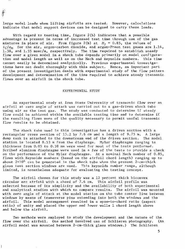
An e x p e r i m e n t a l s t u d y a t Iowa S t a t e U n i v e r s i t y of t r a n s o n i c f low over a n a i r f o i l a t zero a n g l e of a t t a c k w a s c a r r i e d o u t i n a gas-dr iven shock t u b e u s i n g a i r as t h e t es t gas . The s t u d y w a s conducted t o de te rmine i f s t e a d y f low could b e achieved w i t h i n t h e a v a i l a b l e t e s t i n g t i m e and t o de te rmine i f t h e r e s u l t i n g f lows w e r e of t h e q u a l i t y n e c e s s a r y t o permi t u s e f u l t r a n s o n i c f low r e s u l t s t o b e o b t a i n e d .
The shock t u b e used i n t h i s i n v e s t i g a t i o n h a s a d r i v e n s e c t i o n w i t h a r e c t a n g u l a r c r o s s s e c t i o n of 15 .2 by 7 .6 c m and a l e n g t h of 9.75 m. A l a r g e dump t a n k i s a t t a c h e d t o t h e downstream end of t h e d r i v e n s e c t i o n . The model s t a t i o n is l o c a t e d 8.53 m from t h e diaphragm. Mylar diaphragms r a n g i n g i n t h i c k n e s s from 0.05 t o 0.38 mm w e r e used f o r most of t h e tests performed. Scr ibed aluminum diaphragms w e r e used i n a few of t h e tests t o p r o v i d e a check on t h e performance of t h e Mylar diaphragms. A t a nominal Mach number of 0.85, f lows w i t h Reynolds numbers (based on t h e a i r f o i l chord l e n g t h ) ranging up t o about 2 ~ 1 0 ~ can b e g e n e r a t e d i n t h e shock t u b e when t h e pres 'ent 2-cm-thick g l a s s test s e c t i o n windows are used. This Reynolds number range , a l t h o u g h l i m i t e d , i s n o n e t h e l e s s a d e q u a t e f o r e v a l u a t i n g t h e t e s t i n g concept .
The a i r f o i l chosen f o r t h i s s t u d y w a s a 1 2 p e r c e n t t h i c k biconvex c i r c u l a r arc a i r f o i l w i t h a chord of 7 .6 cm. T h i s a i r f o i l p r o f i l e w a s s e l e c t e d because of i t s s i m p l i c i t y and t h e a v a i l a b i l i t y of b o t h e x p e r i m e n t a l and a n a l y t i c a l s t u d i e s w i t h which t o compare r e s u l t s . The a i r f o i l w a s mounted w i t h z e r o a n g l e of a t t a c k a t t h e model s t a t i o n on t h e t u b e c e n t e r l i n e between windows by means of t r a n s v e r s e p i n s e x t e n d i n g i n t o b o t h t h e windows and t h e a i r f o i l . This model arrangement r e s u l t e d i n a span-to-chord r a t i o ( a s p e c t r a t i o ) of u n i t y and p l a c e d t h e upper and lower w a l l s 1 chord l e n g t h above and below t h e a i r f o i l .
Two methods w e r e employed t o s t u d y t h e development and t h e n a t u r e of t h e f low o v e r t h e a i r f o i l . One method involved u s e of S c h l i e r e n photography. (An a i r f o i l model w a s mounted between 2-cm-thick g l a s s windows.) The S c h l i e r e n
5
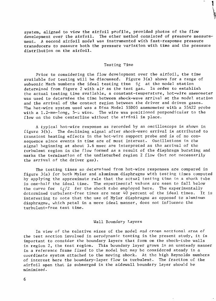
system, a l i g n e d t o v i e w t h e a i r f o i l p r o f i l e , p rovided photos o f t h e f low development o v e r t h e a i r f o i l . ment. A second a i r f o i l model w a s ins t rumented w i t h f a s t - r e s p o n s e p r e s s u r e t r a n s d u c e r s t o measure b o t h t h e p r e s s u r e v a r i a t i o n w i t h t i m e and t h e p r e s s u r e d i s t r i b u t i o n on t h e a i r f o i l .
The o t h e r method c o n s i s t e d of p r e s s u r e measure-
T e s t i n g T i m e
P r i o r t o c o n s i d e r i n g t h e f low development o v e r t h e a i r f o i l , t h e t i m e a v a i l a b l e f o r t e s t i n g w i l l b e d i s c u s s e d . F i g u r e 3 ( a ) shows f o r a range of s u b s o n i c Mach numbers t h e i d e a l t e s t i n g t i m e ti a t t h e model s t a t i o n determined from f i g u r e 2 w i t h a i r as t h e test gas . I n o r d e r t o e s t a b l i s h t h e a c t u a l t e s t i n g t i m e a v a i l a b l e , a cons tan t - tempera ture , hot-wire anemometer w a s used t o d e t e r m i n e t h e t i m e between shock-wave a r r iva l a t t h e model s t a t i o n and t h e a r r i v a l of t h e c o n t a c t r e g i o n between t h e d r i v e r and d r i v e n g a s e s . The hot-wire system used w a s a D i s a Model 55D05 anemometer w i t h a 55A22 probe w i t h a 1.2-mm-long, 5-u w i r e . The w i r e w a s p o s i t i o n e d p e r p e n d i c u l a r t o t h e f low on t h e t u b e c e n t e r l i n e w i t h o u t t h e a i r f o i l i n p l a c e .
A t y p i c a l ho t -wire r e s p o n s e as recorded by an o s c i l l o s c o p e is shown i n f i g u r e 3 ( b ) . The d e c l i n i n g s i g n a l a f t e r shock-wave a r r iva l i s a t t r i b u t e d t o t r a n s i e n t h e a t i n g e f f e c t s i n t h e hot-wire s u p p o r t p robe and i s of no con- sequence s i n c e e v e n t s i n t i m e are of most i n t e r e s t . O s c i l l a t i o n s i n t h e s i g n a l beginning a t about 3 .6 m s e c a re i n t e r p r e t e d as t h e a r r iva l of t h e t u r b u l e n t r e g i o n i n t h e f low formed as a r e s u l t of t h e diaphragm b u r s t i n g and marks t h e t e r m i n a t i o n of t h e u n d i s t u r b e d r e g i o n 2 f low (but n o t n e c e s s a r i l y t h e a r r iva l of t h e d r i v e r g a s ) .
The t e s t i n g t i m e s s o determined from hot-wire r e s p o n s e s are compared i n f i g u r e 3 ( a ) f o r b o t h Mylar and aluminum diaphragms w i t h t e s t i n g t i m e s computed by a p p l y i n g t h e approximate r u l e t h a t t h e a c t u a l t e s t i n g t i m e i n a shock t u b e is one-half t h e i d e a l t i m e . The e x p e r i m e n t a l v a l u e s are s e e n t o f a l l below t h e c u r v e f o r t i l 2 f o r t h e shock t u b e employed h e r e . The e x p e r i m e n t a l l y determined t u r b u l e n t - f r e e t i m e s are n e a r 40 p e r c e n t of t h e i d e a l t i m e s . It i s i n t e r e s t i n g t o n o t e t h a t t h e u s e of Mylar diaphragms as opposed t o aluminum diaphragms, which p e t a l i n a more i d e a l manner, does n o t i n f l u e n c e t h e t u r b u l e n t - f r e e t es t t i m e .
Wall Boundary Layers
I n v i e w of t h e r e l a t ive s i z e s of t h e model and c r o s s s e c t i o n a l area of t h e t e s t s e c t i o n involved i n aerodynamic t e s t i n g i n t h e p r e s e n t s t u d y , i t i s impor tan t t o c o n s i d e r t h e boundary l a y e r s t h a t form on t h e shock-tube w a l l s i n r e g i o n 2 , t h e t e s t r e g i o n . This boundary l a y e r grows i n a n uns teady manner i n a r e f e r e n c e frame f i x e d t o t h e model b u t may b e cons idered s t e a d y i n a c o o r d i n a t e system a t t a c h e d t o t h e moving shock. of i n t e r e s t h e r e t h e boundary-layer f l o w is t u r b u l e n t . The f r a c t i o n of t h e a i r f o i l span t h a t is submerged i n t h e s i d e w a l l boundary l a y e r should b e minimized.
A t t h e h igh Reynolds numbers
6
r
Mirels ( r e f . 10) h a s t r e a t e d t h e shock-tube s i d e w a l l t u r b u l e n t boundary l a y e r i n d e t a i l . The boundary-layer t h i c k n e s s on t h e w a l l a t t h e model sta- t i o n i s shown as a f u n c t i o n o f t i m e f o r t h e shock t u b e used f o r several v a l u e s 3f Re, (e = 7.62 cm) i n f i g u r e 4 ( a ) f o r M, = 0.85. The two smaller v a l u e s >f R e , shown are i n t h e Reynolds number r a n g e of t h e p r e s e n t s t u d y . The two l a r g e r v a l u e s are i n c l u d e d f o r i l l u s t r a t i v e purposes . The t h i c k n e s s c u r v e s i n f i g u r e 4 ( a ) assume t h a t t h e boundary l a y e r is t u r b u l e n t immediately behind t h e shock and as a r e s u l t t end t o o v e r - p r e d i c t t h e t h i c k n e s s a t e a r l y t i m e s m d l o w Reynolds numbers. T h i s is i l l u s t r a t e d i n f i g u r e 4 ( b ) i n which mea- qurements of t h e boundary-layer t h i c k n e s s made from S c h l i e r e n photos of t h e t u r b u l e n t s i d e w a l l boundary l a y e r are compared w i t h t h o s e p r e d i c t e d by t h e .iirels' method, and w i t h Mirels' method c o r r e c t e d f o r t h e f a c t t h a t t h e loundary l a y e r remains laminar f o r a d i s t a n c e behind t h e shock. The method i s e d t o compute t h e c o r r e c t e d boundary-layer t h i c k n e s s involved assuming t h a t i h e t u r b u l e n t boundary l a y e r grows from t h e approximate p o i n t a t which loundary-Payer t r a n s i t i o n t a k e s p l a c e . This p o i n t , termed t h e v i r t u a l o r i g i n 3f t u r b u l e n c e , w a s e s t a b l i s h e d by assuming t h a t t r a n s i t i o n t o o k p l a c e a t a teynolds number of 7 . 5 ~ 1 0 ~ based on c o n d i t i o n s r e l a t ive t o t h e shock wave. r'he measured t h i c k n e s s e s and t h o s e p r e d i c t e d by a p p l i c a t i o f i of Mirels' method i s i n g t h e v i r t u a l o r i g i n are i n good agreement f o r t h e case shown. The - e s u l t s show t h a t t h e c o r r e c t i o n f o r t h e v i r t u a l o r i g i n becomes less impor tan t s i t h i n c r e a s i n g t i m e . E x t r a p o l a t i o n of t h e r e s u l t s i n f i g u r e 4 ( b ) i n d i c a t e s _ h a t a t 3 m s e c t h e v i r t u a l o r i g i n c o r r e c t i o n would b e s m a l l and t h a t t h e Joundary-layer t h i c k n e s s i s c l o s e t o t h a t p r e d i c t e d d i r e c t l y by Mirels' ne thod .
It i s s e e n from f i g u r e 4 ( a ) t h a t a s i z a b l e p o r t i o n of t h e 7.60-cm span I f t h e a i r f o i l i s submerged i n t h e w a l l boundary l a y e r s by t h e end of t h e i v a i l a b l e t e s t i n g t i m e of approximate ly 3 m s e c (determined from f i g . 3 ( a ) a t I , = 0.85) . ghat mis leading . The t u r b u l e n t s i d e w a l l boundary-layer v e l o c i t y p r o f i l e can le approximated by t h e 1 / 7 t h power l a w . This i n d i c a t e s t h a t t h e major p o r t i o n if t h e v e l o c i t y d e f i c i t i s n e a r t h e s i d e w a l l ; f o r example, t h e f r a c t i o n of he span covered t o t h e p o i n t i n t h e two s i d e w a l l boundary l a y e r s , where t h e
r e l o c i t y i s 80 p e r c e n t of t h e f r e e - s t r e a m v e l o c i t y , i s 0.10. Accord ingly , IO l a r g e v e l o c i t y g r a d i e n t s w e r e expec ted i n t h e spanwise d i r e c t i o n f o r t h e llajor p o r t i o n of t h e span.
For Re, = 2x10⁶, 2 6 / c = 0.46; however, t h i s f i g u r e can b e some-
I n f l u e n c e of Walls on Flow F i e l d
A p a r t i c u l a r l y impor tan t c o n s i d e r a t i o n i n t r a n s o n i c t e s t i n g f a c i l i t i e s i s t h e i n f l u e n c e of t h e f a c i l i t y w a l l s on t h e f low f i e l d around t h e model. )ne measure of t h i s i n f l u e n c e is t h e amount of b lockage t h a t r e s u l t s due t o h e p r e s e n c e of t h e model. This c o n s i d e r a t i o n i s d i s c u s s e d e x t e n s i v e l y i n - e f e r e n c e 11. A t a Mach number of 0.85, a b lockage ( c r o s s - s e c t i o n area of he model t o t h a t of t h e f low channel ) of about 2 p e r c e n t c a u s e s choking. I n ~ r d e r t o avoid s i g n i f i c a n t f low d i s t o r t i o n s , t h e a c t u a l b lockage should b e - 0 n s i d e r a b l y less t h a n 2 p e r c e n t . It i s e v i d e n t i n t h e p r e s e n t case t h a t t h i s l o n d i t i o n is n o t s a t i s f i e d .
7
1
Two methods are a v a i l a b l e t o overcome b lockage e f f e c t s i n aerodynamic tes t f a c i l i t i e s . These are (1) u s e of p e r f o r a t e d o r s l o t t e d w a l l s w i t h a d j a c e n t chambers t h a t t end t o a u t o m a t i c a l l y r e g u l a t e t h e f low around t h e model t o r e n d e r a f l o w p a t t e r n c l o s e t o t h a t encountered i n f r e e f l i g h t , and (2) u s e of w a l l s contoured t o match s t r e a m l i n e s t h a t occur i n f r e e f l i g h t . Although p e r f o r a t e d and s l o t t e d w a l l s have been used e x t e n s i v e l y i n t r a n s o n i c wind t u n n e l s , such w a l l s have a p p a r e n t l y n o t been used i n aerodynamic t e s t i n g i n shock tubes .
I n v i e w of t h e c o m p l e x i t i e s involved i n d e s i g n of a p e r f o r a t e d o r s l o t t e d tes t s e c t i o n , t h e method used t o d e a l w i t h b lockage i n t h e p r e s e n t s t u d y w a s w a l l contour ing . The r e c e n t work of Murman and Cole ( r e f . 1 2 ) and Murman ( r e f . 1 3 ) , which i s based on t r a n s o n i c s m a l l d i s t u r b a n c e t h e o r y , p r o v i d e s a means of o b t a i n i n g p o t e n t i a l f low stream s u r f a c e s as w e l l as p o t e n t i a l f l o w f i e l d s ( i n c l u d i n g imbedded shock waves) f o r t h i n two-dimensional t r a n s o n i c a i r f o i l s a t z e r o a n g l e of a t t a c k . Due t o t h e i r i n v i s c i d n a t u r e , such s o l u - t i o n s would n o t b e expec ted t o a c c u r a t e l y d e s c r i b e t h e f low f i e l d n e a r t h e a i r f o i l where boundary-layer e f f e c t s are i m p o r t a n t , b u t would b e expec ted t o y i e l d r e a s o n a b l y a c c u r a t e r e s u l t s f o r t h e f low w e l l away from t h e model.
The s l o p e as a f u n c t i o n of p o s i t i o n f o r stream s u r f a c e s of t h e f low 1 chord l e n g t h above and below t h e model w a s o b t a i n e d by t h e methods of r e f - e r e n c e s 1 2 and 1 3 l f o r t h e t e s t a i r f o i l a t t es t Mach numbers of 0.83, 0.85, and 0.87. The i n f l u e n c e of t h e t i m e dependent t u r b u l e n t s i d e w a l l boundary l a y e r w a s accounted f o r i n an approximate manner i n t h e computat ion of t h e f i n a l w a l l c o n t o u r . This w a s done by computing t h e s l o p e of t h e d isp lacement t h i c k n e s s f o r t h e t u r b u l e n t s i d e w a l l boundary l a y e r by means of r e f e r e n c e 10 and adding t h i s s l o p e a l g e b r a i c a l l y t o t h e s l o p e of t h e stream s u r f a c e . The r e s u l t i n g s l o p e w a s t h e n i n t e g r a t e d w i t h p o s i t i o n t o p r o v i d e t h e f i n a l w a l l c o n t o u r s . The w a l l c o n t o u r s determined i n t h i s manner a re shown i n f i g u r e 5. S e p a r a t e c o n t o u r s f o r t h e t h r e e Mach numbers w e r e t h e n machined i n t o t h e b l o c k s t h a t compose t h e upper and lower w a l l s of t h e t e s t s e c t i o n . The c o n t o u r s extended from 1 . 8 chord l e n g t h s upstream of t h e l e a d i n g edge of t h e a i r f o i l t o about 3 chord l e n g t h s downstream of t h e t r a i l i n g edge.
A i r f o i l P r e s s u r e Measurements
A s no ted p r e v i o u s l y , one means of s t u d y i n g t h e a i r f o i l f lows g e n e r a t e d w a s by means of p r e s s u r e measurements made on t h e a i r f o i l s u r f a c e . f a s t - r e s p o n s e K u l i t e p r e s s u r e t r a n s d u c e r s having r ise t i m e s of approximate ly 10 psec w e r e used.
S i x s m a l l
The t r a n s d u c e r s w e r e p laced a t midspan of t h e a i r f o i l f l u s h w i t h t h e s u r f a c e i n 5-mm-wide spanwise grooves t h a t a l s o s e r v e d a s channels f o r t h e
IThe a u t h o r s are indebted t o D r . E a r l 1 Murman f o r h i s c o n s u l t a t i o n and f o r p r o v i d i n g t h e computer program r e l a t e d t o t h e methods of r e f e r e n c e s 1 2 and 13.
8
t r a n s d u c e r e lectr ical l e a d s . P a r a f f i n w a x used t o cover t h e l e a d s and f i l l t h e grooves w a s trimmed t o m a i n t a i n t h e a i r f o i l p r o f i l e . F i g u r e 6 shows a photo of t h e ins t rumented a i r f o i l , mounted on a n aluminum d i s c which w a s machined t o r e p l a c e one of t h e g l a s s windows. The t r a n s d u c e r e lectr ical l e a d s w e r e passed through r u b b e r vacuum seals on t h e f a r s i d e of t h e d i s c . The 15-cm scale p r o v i d e s a s i z e r e f e r e n c e . The numbers on t h e a i r f o i l d e n o t e t h e s ix t r a n s d u c e r s , t h e s e n s i n g s u r f a c e s of which are l o c a t e d n e a r t h e t e r m i n a t i o n of t h e grooves. Transducers w e r e p l a c e d a t v a l u e s of x / c of 0.20, 0.40 , 0.60, 0.70, 0.80, and 0.88. T h i s series of p o s i t i o n s w a s d e s i g n a t e d as p a t t e r n A.
Due t o t h e symmetry of t h e a i r f o i l p r o f i l e and w a l l c o n t o u r s , r o t a t i n g t h e a i r f o i l one-half t u r n t o i n t e r c h a n g e t h e l e a d i n g and t r a i l i n g edges p e r m i t t e d measurements t o b e made a t a d d i t i o n a l x / e l o c a t i o n s of 0.12 and 0.30, and exchanged t r a n s d u c e r s a t x / c p o s i t i o n s a t 0.20 and 0.80 as w e l l as a t 0.40 and 0.60. T h i s series of p o s i t i o n s w a s d e s i g n a t e d as p a t t e r n B. For some tests two gages w e r e p o s i t i o n e d a t x / e = 0.60, one a t midspan and one 2.5 c m away from midspan, i n o r d e r t o o b t a i n a n i n d i c a t i o n of any spanwise f low v a r i a t i o n . Unless o t h e r w i s e n o t e d , t h e measurements d i s c u s s e d and p r e s e n t e d h e r e i n are from t e s t s i n which t h e gages w e r e l o c a t e d a t midspan.
F i g u r e 7 i s a schemat ic of t h e p r e s s u r e measurement system. The complete t r a n s d u c e r c i r c u i t c o n s i s t s of an i n t e g r a t e d c i r c u i t Wheatstone b r i d g e formed on a s i l i c o n diaphragm and a tempera ture compensation module. The b r i d g e w a s e x c i t e d by means of a b a t t e r y . The e x c i t a t i o n v o l t a g e w a s monitored by a d i g i t a l v o l t m e t e r . response r e c o r d s t o b e recorded on each P o l a r o i d photo. A m i l l i v o l t m e t e r r e p l a c e d t h e o s c i l l o s c o p e t o c a l i b r a t e t h e t r a n s d u c e r s . I n o r d e r t o o b t a i n r e s u l t s t h a t w e r e as a c c u r a t e as p o s s i b l e , t h e t r a n s d u c e r s w e r e c a l i b r a t e d b e f o r e each series of r u n s . T h i s w a s accomplished by making s t a t i c measure- ments of p r e s s u r e and t r a n s d u c e r v o l t a g e w i t h t h e a i r f o i l mounted i n t h e t es t s e c t i o n of t h e shock tube. S e v e r a l vacuum gages t h a t are used t o measure t h e t e s t s e c t i o n p r e s s u r e provided measurement and c r o s s checks of t h e p r e s s u r e i n t h e d e s i r e d range of c a l i b r a t i o n .
U s e of d u a l beam o s c i l l o s c o p e s p e r m i t t e d two gage
RESULTS
S c h l i e r e n Photography
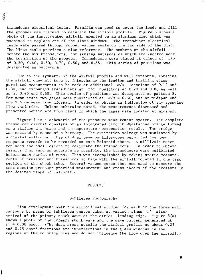
Flow development o v e r t h e a i r f o i l w a s s t u d i e d f o r each of t h e t h r e e w a l l c o n t o u r s by means of S c h l i e r e n photos taken a t v a r i o u s t i m e s t' a f t e r a r r i v a l of t h e pr imary shock wave a t t h e a i r f o i l l e a d i n g edge. F i g u r e 8 ( a ) shows a photo of t h e pr imary shock wave and t h e wave p a t t e r n genera ted a t t' A 0.08 msec. and 0.75 chord f r a c t i o n s are i m p e r f e c t i o n s i n t h e g l a s s windows i n t h e r e g i o n s of t h e mounting p i n s and do n o t i n f l u e n c e t h e f low o v e r t h e a i r f o i l . )
(The d a r k areas o u t s i d e t h e a i r f o i l p r o f i l e a t about 0.25
9
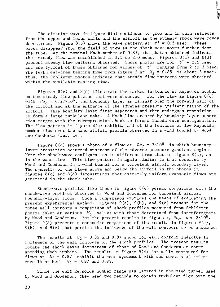
The c i r c u l a r wave i n f i g u r e 8 ( a ) c o n t i n u e s t o grow and i n t u r n r e f l e c t s from t h e upper and lower w a l l s and t h e a i r f o i l as t h e pr imary shock wave moves downstream. F i g u r e 8 ( b ) shows t h e wave p a t t e r n a t t' = 0.5 msec. These waves d i s a p p e a r from t h e f i e l d of v i e w as t h e shock wave moves f u r t h e r down t h e tube . A t t h e nominal Mach number of 0 .85 , t h e photos o b t a i n e d i n d i c a t e t h a t s t e a d y f l o w w a s e s t a b l i s h e d i n 1 . 5 t o 2.0 msec. F i g u r e s 8 ( c ) and 8 ( d ) p r e s e n t s t e a d y f low p a t t e r n s observed. These photos are f o r t' = 2.5 m s e c and are t y p i c a l of t h o s e o b t a i n e d f o r v a l u e s of The t u r b u l e n t - f r e e t e s t i n g t i m e from f i g u r e 3 a t Thus, t h e S c h l i e r e n photos i n d i c a t e t h a t s t e a d y f low p a t t e r n s w e r e o b t a i n e d w i t h i n t h e a v a i l a b l e t e s t i n g t i m e .
t' r a n g i n g from 2 t o 3 msec. M, = 0.85 is about 3 msec.
F i g u r e s 8 ( c ) and 8 ( d ) i l l u s t r a t e t h e marked i n f l u e n c e of Reynolds number For t h e f low i n f i g u r e 8 ( c )
Re, = O.27x1O6, t h e boundary l a y e r i s laminar over t h e forward h a l f of on t h e s t e a d y f low p a t t e r n s t h a t w e r e observed. w i t h t h e a i r f o i l and a t t h e e n t r a n c e of t h e a d v e r s e p r e s s u r e g r a d i e n t r e g i o n of t h e a i r f o i l . T h i s boundary l a y e r f i r s t s e p a r a t e s and t h e n undergoes t r a n s i t i o n t o form a l a r g e t u r b u l e n t wake. A Mach l i n e c r e a t e d by boundary-layer separa- t i o n merges w i t h t h e recompression shock t o form a lambda wave c o n f i g u r a t i o n . The f low p a t t e r n i n f i g u r e 8 ( c ) e x h i b i t s a l l of t h e f e a t u r e s of low Reynolds number f low o v e r t h e same a i r f o i l p r o f i l e observed i n a wind t u n n e l by Wood and- Gooderum ( r e f . 1 4 ) .
F i g u r e 8 ( d ) shows a photo of a f low a t Re, = 2 ~ 1 0 ~ i n which boundary- l a y e r t r a n s i t i o n o c c u r r e d upstream of t h e a d v e r s e p r e s s u r e g r a d i e n t r e g i o n . Here t h e shock-wave c o n f i g u r a t i o n i s d i f f e r e n t from t h a t i n f i g u r e 8 ( c ) , as i s t h e wake f low. T h i s f low p a t t e r n i s a g a i n s i m i l a r t o t h a t observed by Wood and Gooderum i n a wind t u n n e l f o r a t u r b u l e n t a i r f o i l boundary l a y e r . The symmetry of t h e f lows above and below t h e a i r f o i l i n t h e photos i n f i g u r e s 8 ( c ) and 8 ( d ) demonst ra tes t h a t ex t remely uniform t r a n s o n i c f lows a re g e n e r a t e d i n t h e shock tube .
Shock-wave p r o f i l e s l i k e t h o s e i n f i g u r e 8 ( d ) permi t comparison w i t h t h e shock-wave p r o f i l e s observed by Wood and Gooderum f o r t u r b u l e n t a i r f o i l boundary-layer f lows . Such a comparison p r o v i d e s one means of e v a l u a t i n g t h e p r e s e n t exper imenta l method. F i g u r e s 9 ( a ) , 9 ( b ) , and 9 ( c ) p r e s e n t f o r t h e t h r e e w a l l c o n t o u r s a comparison of shock p r o f i l e s measured from S c h l i e r e n photos t a k e n a t v a r i o u s M, by Wood and Gooderum. w a s 2 ~ 1 0 ~ . F i g u r e 9 ( d ) p r e s e n t s a composi te comparison of t h e r e s u l t s i n f i g u r e s 9 ( a ) , 9 ( b ) , and 9 ( c ) t h a t p e r m i t s t h e i n f l u e n c e of t h e w a l l c o n t o u r s t o be a s s e s s e d .
v a l u e s w i t h t h o s e determined from i n t e r f e r o g r a m s For t h e p r e s e n t r e s u l t s i n f i g u r e 9 , Re,
The r e s u l t s a t M, = 0.85 and 0.87 shown f o r each contour i n d i c a t e an i n f l u e n c e of t h e w a l l c o n t o u r s on t h e shock p r o f i l e s . The p r e s e n t r e s u l t s l o c a t e t h e shock waves downstream of t h o s e of Wood and Gooderum a t c o r r e - sponding Mach numbers. The r e s u l t s i n f i g u r e 9(d) f o r w a l l s contoured f o r f lows a t M;! = 0.87 e x h i b i t t h e b e s t agreement w i t h t h e r e s u l t s of r e f e r - ence 1 4 a t b o t h M, = 0.87 and 0.85.
S i n c e t h e u n i t Reynolds number range w a s l i m i t e d i n t h e wind t u n n e l used by Wood and Gooderum, they used two methods t o o b t a i n t u r b u l e n t f low over t h e
10
l - i n . chord l e n g t h a i r f o i l s t e s t e d . One method involved s t r e t c h i n g a s m a l l - d iameter w i r e a c r o s s t h e test s e c t i o n about 1 chord l e n g t h upstream of t h e a i r f o i l l e a d i n g edge t o produce t u r b u l e n c e . t h i n f l a t p l a t e 1 chord l e n g t h upstream a l o n g t h e a i r f o i l chord l i n e t o gen- erate a t u r b u l e n t boundary l a y e r over t h e a i r f o i l . I n t h e p r e s e n t s t u d y , t h e Reynolds number w a s l a r g e enough t o permi t n a t u r a l boundary-layer t r a n s i t i o n t o o c c u r on t h e a i r f o i l .
The o t h e r involved ex tending a
I n v i e w of t h e s e n s i t i v i t y of t h e shock-wave p a t t e r n t o t h e n a t u r e of t h e a i r f o i l boundary l a y e r , it i s l i k e l y t h a t t h e d i f f e r e n c e s i n f i g u r e 9 between t h e p r e s e n t shock-wave p r o f i l e s and t h o s e of r e f e r e n c e 1 4 are a t t r i b u t a b l e t o t h e d i f f e r e n c e s i n t h e manner i n which t h e t u r b u l e n t boundary l a y e r formed. This i s borne o u t t o some e x t e n t by S c h l i e r e n photos t a k e n i n t h e p r e s e n t s t u d y f o r f lows a t smooth to permi t n a t u r a l boundary-layer t r a n s i t i o n and t h e o t h e r s u r f a c e roughened t o promote boundary-layer t r a n s i t i o n . F i g u r e 10 shows one of t h e s e photos . (The d a r k area n e a r t h e l e a d i n g edge is a r e p a i r e d f r a c t u r e i n one g l a s s window.) It is s e e n t h a t t h e shock p r o f i l e f o r t h e roughened s i d e l i e s upstream of t h e shock p r o f i l e f o r t h e smooth s i d e .
Re, = 1 . 2 5 ~ 1 0 ~ o v e r t h e a i r f o i l w i t h one f low s u r f a c e
P r e s s u r e R e s u l t s
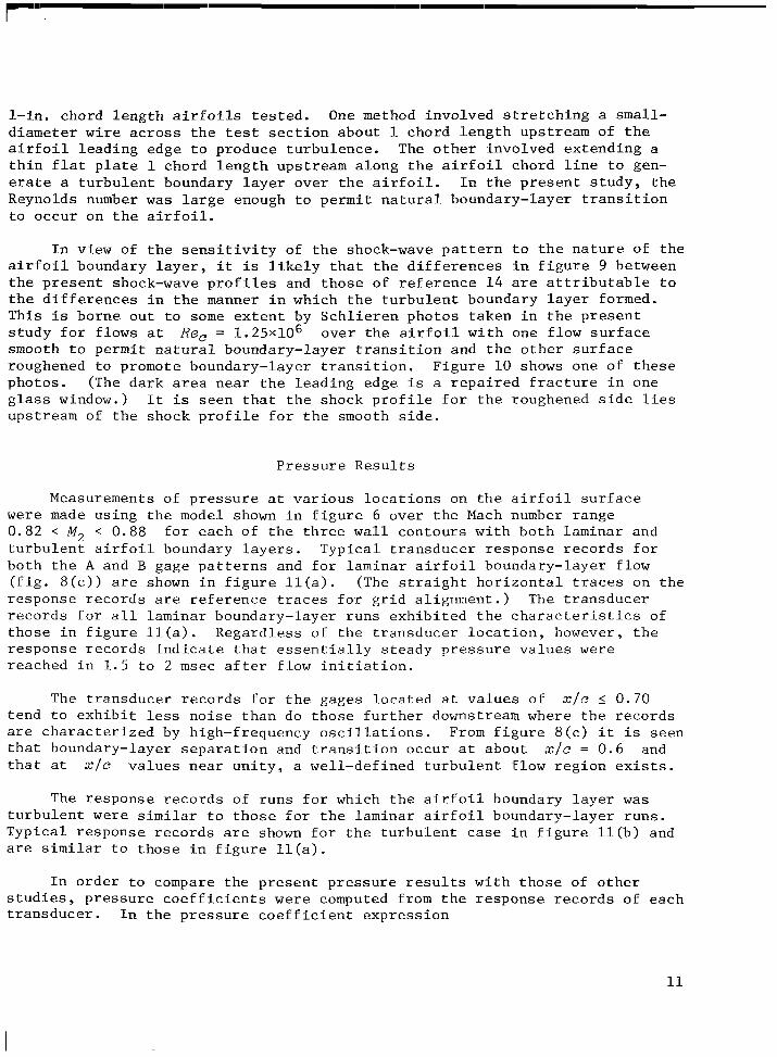
Measurements of p r e s s u r e a t v a r i o u s l o c a t i o n s on t h e a i r f o i l s u r f a c e w e r e made us ing t h e model shown i n f i g u r e 6 over t h e Mach number range 0.82 < M, < 0.88 f o r each of t h e t h r e e w a l l c o n t o u r s w i t h b o t h laminar and t u r b u l e n t a i r f o i l boundary l a y e r s . T y p i c a l t r a n s d u c e r r e s p o n s e r e c o r d s f o r b o t h t h e A and B gage p a t t e r n s and f o r laminar a i r f o i l boundary-layer f low ( f i g . 8 ( c ) ) a r e shown i n f i g u r e l l ( a ) . (The s t r a i g h t h o r i z o n t a l traces on t h e r e s p o n s e r e c o r d s a r e r e f e r e n c e t r a c e s f o r g r i d a l i g n m e n t . ) The t r a n s d u c e r r e c o r d s f o r a l l laminar boundary-layer r u n s e x h i b i t e d t h e c h a r a c t e r i s t i c s of t h o s e i n f i g u r e l l ( a ) . Regard less of t h e t r a n s d u c e r l o c a t i o n , however, t h e r e s p o n s e r e c o r d s i n d i c a t e t h a t e s s e n t i a l l y s t e a d y p r e s s u r e v a l u e s w e r e reached i n 1 . 5 t o 2 m s e c a f t e r f low i n i t i a t i o n .
The t r a n s d u c e r r e c o r d s f o r t h e gages l o c a t e d a t v a l u e s of x / c I 0.70 tend t o e x h i b i t less n o i s e t h a n do t h o s e f u r t h e r downstream where t h e r e c o r d s are c h a r a c t e r i z e d by high-frequency o s c i l l a t i o n s . From f i g u r e 8 ( c ) i t is s e e n t h a t boundary-layer s e p a r a t i o n and t r a n s i t i o n occur a t about xlc = 0.6 and t h a t a t x / c v a l u e s n e a r u n i t y , a wel l -def ined t u r b u l e n t f low r e g i o n e x i s t s .
The r e s p o n s e r e c o r d s of r u n s f o r which t h e a i r f o i l boundary l a y e r w a s t u r b u l e n t w e r e s i m i l a r t o t h o s e f o r t h e laminar a i r f o i l boundary-layer r u n s . T y p i c a l r e s p o n s e r e c o r d s are shown f o r t h e t u r b u l e n t case i n f i g u r e l l ( b ) and are s i m i l a r t o t h o s e i n f i g u r e l l ( a ) .
I n o r d e r t o compare t h e p r e s e n t p r e s s u r e r e s u l t s w i t h t h o s e of o t h e r s t u d i e s , p r e s s u r e c o e f f i c i e n t s w e r e computed from t h e r e s p o n s e r e c o r d s of each t r a n s d u c e r . I n t h e p r e s s u r e c o e f f i c i e n t e x p r e s s i o n
11
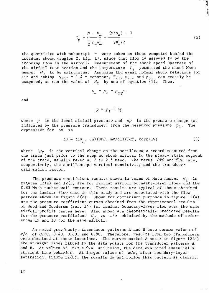
t h e q u a n t i t i e s w i t h s u b s c r i p t m w e r e t a k e n as t h o s e computed behind t h e i n c i d e n t shock ( r e g i o n 2, f i g . l ) , s i n c e t h a t f low is assumed t o be t h e incoming f low t o t h e a i r f o i l . Measurement of t h e shock speed upstream of t h e a i r f o i l tes t s e c t i o n and t h e tempera ture number M, t o b e c a l c u l a t e d . Assuming t h e u s u a l normal shock r e l a t i o n s f o r a i r and t a k i n g -yair = 1 . 4 = c o n s t a n t , T21, p21, and p can r e a d i l y b e computed, as can t h e v a l u e of
T1
by use of e q u a t i o n pi).
p e r m i t t e d t h e shock Mach
M, Then,
and
where p i s t h e l o c a l a i r f o i l p r e s s u r e and Ap i s t h e p r e s s u r e change ( a s i n d i c a t e d by t h e p r e s s u r e t r a n s d u c e r ) from t h e measured p r e s s u r e p l . The e x p r e s s i o n f o r Ap is
Ap = (Ay,, cm) (OVS , mV/cm> (TCF, torr/mV) ( 6 )
where Ay, i s t h e v e r t i c a l change on t h e o s c i l l o s c o p e r e c o r d measured from t h e t race j u s t p r i o r t o t h e s t e p a t shock a r r iva l t o t h e s t e a d y s t a t e segment of t h e trace, u s u a l l y t a k e n a t 2 t o 2.5 m s e c . The t e r m s OVS and TCF are , r e s p e c t i v e l y , t h e o s c i l l o s c o p e ve r t i ca l s e n s i t i v i t y and t h e t r a n s d u c e r c a l i b r a t i o n f a c t o r .
The p r e s s u r e c o e f f i c i e n t r e s u l t s shown i n t e r m s of Mach number M2 i n f i g u r e s 1 2 ( a ) and 1 2 ( b ) a re f o r laminar a i r f o i l boundary-layer f lows and t h e 0.83 Mach number w a l l contour . These r e s u l t s are t y p i c a l of t h o s e o b t a i n e d f o r t h e laminar f low case i n t h i s s t u d y and are a s s o c i a t e d w i t h t h e f low p a t t e r n shown i n f i g u r e 8 ( c ) . Shown f o r comparison purposes i n f i g u r e 1 2 ( a ) are t h e p r e s s u r e c o e f f i c i e n t curves o b t a i n e d from t h e exper imenta l r e s u l t s of Wood and Gooderum ( r e f . 1 4 ) f o r l a m i n a r boundary-layer f low over t h e s a m e a i r f o i l p r o f i l e t e s t e d h e r e . Also shown are t h e o r e t i c a l l y p r e d i c t e d r e s u l t s f o r t h e p r e s s u r e c o e f f i c i e n t Cp v s x / c o b t a i n e d by t h e methods of r e f e r - ences 12 and 1 3 f o r t h e s a m e a i r f o i l .
A s no ted p r e v i o u s l y , t r a n s d u c e r p a t t e r n s A and B have common v a l u e s of x / c of 0.20, 0 .40 , 0.60, and 0.80. T h e r e f o r e , r e s u l t s from two t r a n s d u c e r s were o b t a i n e d a t t h e s e l o c a t i o n s . The c u r v e s marked A and B i n f i g u r e 1 2 ( a ) are s t r a i g h t l i n e s f i t t e d t o t h e d a t a p o i n t s f o r t h e t r a n s d u c e r p a t t e r n s A and B. A t v a l u e s of x / c = 0.4 and below, t h e d a t a e x h i b i t e d e s s e n t i a l l y s t r a i g h t l i n e behavior . A t l a r g e r v a l u e s of x / c , a f t e r boundary-layer s e p a r a t i o n , f i g u r e 1 2 ( b ) , t h e r e s u l t s do n o t f o l l o w t h i s p a t t e r n as c l e a r l y .
12
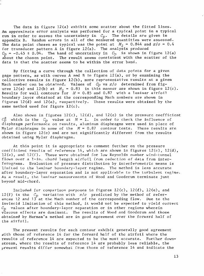
The d a t a i n f i g u r e 1 2 ( a ) e x h i b i t some scat ter about t h e f i t t e d l i n e s . An approximate e r r o r a n a l y s i s w a s performed f o r a t y p i c a l p o i n t i n a t y p i c a l r u n i n o r d e r t o assess t h e u n c e r t a i n t y i n appendix B. The d a t a p o i n t chosen as t y p i c a l w a s t h e p o i n t a t f o r t r a n s d u c e r p a t t e r n A i n f i g u r e 1 2 ( a ) . The a n a l y s i s produced Cp = -0.45 t 0.04. i s shown i n f i g u r e 1 2 ( a ) about t h e chosen p o i n t . The r e s u l t s e e m s c o n s i s t e n t w i t h t h e scat ter of t h e d a t a i n t h a t t h e scatter s e e m s t o b e w i t h i n t h e e r r o r band.
Cp. Random e r r o r s i n a l l of t h e measured q u a n t i t i e s w e r e a s s e s s e d .
M2 = 0.844 and x / c = 0.4
The d e t a i l s are g iven i n
The band of u n c e r t a i n t y i n Cp
By f i t t i n g a c u r v e through t h e c o l l e c t i o n of d a t a p o i n t s f o r a g iven gage p a t t e r n , as w i t h c u r v e s A and B i n f i g u r e 1 2 ( a ) , o r by examining t h e c o l l e c t i v e r e s u l t s i n f i g u r e 1 2 ( b ) , more r e p r e s e n t a t i v e r e s u l t s a t a g iven Mach number can b e o b t a i n e d . Values of Cp vs x / e determined from f i g - u r e s 1 2 ( a ) and 1 2 ( b ) a t R e s u l t s f o r w a l l c o n t o u r s f o r M = 0.85 and 0.87 w i t h a laminar a i r f o i l boundary l a y e r o b t a i n e d a t t h e cor responding Mach numbers are shown i n f i g u r e s 1 2 ( d ) and 1 2 ( e ) , r e s p e c t i v e l y . These r e s u l t s w e r e o b t a i n e d by t h e s a m e method used f o r f i g u r e 1 2 ( c ) .
M, = 0.83 i n t h i s manner are shown i n f i g u r e 1 2 ( c )
Also shown i n f i g u r e s 1 2 ( c ) , 1 2 ( d ) , and 1 2 ( e ) i s t h e p r e s s u r e c o e f f i c i e n t Cp” which i s t h e Cp v a l u e a t M = 1. I n o r d e r t o check t h e i n f l u e n c e of diaphragm performance on r e s u l t s , aluminum diaphragms w e r e used i n p l a c e of Mylar diaphragms i n some of t h e M = 0.87 contour tests. These r e s u l t s a r e shown i n f i g u r e 1 2 ( e ) and are n o t s i g n i f i c a n t l y d i f f e r e n t from t h e r e s u l t s o b t a i n e d us ing Mylar diaphragms.
A t t h i s p o i n t i t i s a p p r o p r i a t e t o comment f u r t h e r on t h e p r e s s u r e c o e f f i c i e n t r e s u l t s of r e f e r e n c e 1 4 , which a r e shown i n f i g u r e s 1 2 ( c ) , 1 2 ( d ) , 1 2 ( e ) , and 1 2 ( f ) . These w e r e o b t a i n e d f o r low Reynolds number wind-tunnel f lows over a 1- in . chord l e n g t h a i r f o i l from r e d u c t i o n of d a t a from i n t e r - ferograms. E v a l u a t i o n o f p r e s s u r e d i s t r i b u t i o n by i n t e r f e r o m e t r i c means i s l i m i t e d t o t h e laminar boundary-layer regime. The method i s less a c c u r a t e a f t e r boundary-layer s e p a r a t i o n and i s n o t a p p l i c a b l e t o t h e t u r b u l e n t regime. A s a r e s u l t , t h e laminar measurements of Wood and Gooderum t e r m i n a t e j u s t beyond mid-chord.
Inc luded f o r comparison purposes i n f i g u r e s 1 2 ( c ) , 1 2 ( d ) , 1 2 ( e ) , and 1 2 ( f ) i s t h e Cp v a r i a t i o n w i t h x / e p r e d i c t e d by t h e method of r e f e r - ences 12 and 1 3 a t t h e Mach number of t h e cor responding f low. Due t o t h e i n v i s c i d l i m i t a t i o n of t h i s method, i t would n o t b e expected t o y i e l d c o r r e c t
Cp v a l u e s a f t e r boundary-layer s e p a r a t i o n o r i n o t h e r r e g i o n s where in v i s c o u s e f f e c t s a re dominant. The r e s u l t s of Wood and Gooderum and t h o s e o b t a i n e d by Murman’s method a re i n good agreement over t h e forward h a l f of t h e a i r f o i l .
The p r e s e n t r e s u l t s f o r each contour e x h i b i t g e n e r a l l y good agreement d i t h t h o s e of r e f e r e n c e 1 4 f o r t h e forward h a l f of t h e a i r f o i l where t h e r e s u l t s of r e f e r e n c e 14 are expected t o b e t h e most a c c u r a t e . F u r t h e r down- stream, where t h e r e s u l t s of r e f e r e n c e 1 4 are probably less r e l i a b l e , t h e p r e s e n t r e s u l t s d i f f e r somewhat from t h o s e of r e f e r e n c e 14 and i n d i c a t e t h e
1 3
expec ted p r e s s u r e i n c r e a s e n e a r t h e t r a i l i n g edge. The g e n e r a l l y good agree- ment of t h e p r e s e n t r e s u l t s w i t h t h e r e s u l t s of r e f e r e n c e 14 p r o v i d e s f u r t h e r ev idence t h a t t r a n s o n i c f lows l i k e t h o s e observed i n wind t u n n e l s can b e produced i n shock t u b e s .
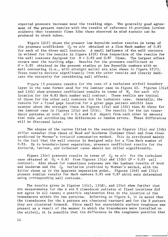
F i g u r e 1 2 ( f ) shows t h e p r e s e n t low Reynolds number r e s u l t s i n t e r m s o f o b t a i n e d a t a f l o w Mach number of 0.85 t h e p r e s s u r e c o e f f i c i e n t
f o r each of t h e t h r e e w a l l c o n t o u r s . A s m a l l i n f l u e n c e of t h e w a l l c o n t o u r s is e v i d e n t f o r t h e r e s u l t s i n f i g u r e 1 2 ( f ) from i n s p e c t i o n of t h e r e s u l t s f o r t h e w a l l c o n t o u r s des igned f o r M = 0.83 and 0.87 f lows. The l a r g e s t e f f e c t o c c u r s n e a r t h e t r a i l i n g edge. R e s u l t s f o r t h e p r e s s u r e c o e f f i c i e n t a t M = 0.85 o b t a i n e d i n t h e p r e s e n t s t u d i e s a t low Reynolds numbers w i t h no w a l l c o n t o u r i n g ( i . e . , w i t h s t r a i g h t w a l l s ) are a l s o shown i n f i g u r e 1 2 ( f ) . These r e s u l t s d e v i a t e s i g n i f i c a n t l y from t h e o t h e r r e s u l t s and c l e a r l y i n d i - cate t h e n e c e s s i t y f o r c o n s i d e r i n g w a l l e f f e c t s .
Cp vs x / c
F i g u r e 1 3 p r e s e n t s r e s u l t s f o r t h e case of a t u r b u l e n t a i r f o i l boundary l a y e r i n t h e same format used f o r t h e laminar case i n f i g u r e 12. F i g u r e s 1 3 ( a ) and 1 3 ( b ) show p r e s s u r e c o e f f i c i e n t r e s u l t s i n t e r m s of M, f o r each x / c l o c a t i o n f o r t h e 0 .83 Mach number w a l l c o n t o u r . These r e s u l t s are t y p i c a l of t h o s e f o r t h e o t h e r w a l l c o n t o u r s f o r t h e t u r b u l e n t case. G e n e r a l l y , t h e r e s u l t s f o r a f i x e d gage l o c a t i o n f o r a g iven gage p a t t e r n e x h i b i t less scatter about t h e s t r a i g h t l i n e s i n f i g u r e s 1 3 ( a ) and 1 3 ( b ) t h a n do t h o s e f o r t h e l a m i n a r case i n f i g u r e s 1 2 ( a ) and 1 2 ( b ) . The r e s u l t s f o r t h e two t r a n s - ducer p a t t e r n s a t b o t h x / c = 0.4 and 0.6 d e p a r t from each o t h e r by amounts t h a t r u l e o u t a t t r i b u t i n g t h e d i f f e r e n c e s t o random e r r o r s . These d i f f e r e n c e s w i l l b e d i s c u s s e d l a te r .
The s l o p e s of t h e c u r v e s f i t t e d t o t h e r e s u l t s i n f i g u r e s 1 3 ( a ) and 1 3 ( b ) d i f f e r somewhat from t h o s e of Wood and Gooderum ( laminar f low) and from t h o s e p r e d i c t e d by Murman's i n v i s c i d computat ion method. This i s a t t r i b u t e d mainly t o t h e f a c t t h a t t h e w a l l contour i s des igned o n l y f o r a f low Mach number of 0.83. Up t o boundary-layer s e p a r a t i o n , p r e s s u r e c o e f f i c i e n t r e s u l t s f o r t h e i n v i s c i d , l a m i n a r , and t u r b u l e n t cases should n o t d i f f e r s i g n i f i c a n t l y .
F i g u r e 1 3 ( c ) p r e s e n t s r e s u l t s i n terms of Cp v s x / c f o r t h e t u r b u l e n t case o b t a i n e d a t f.42 = 0.83 from f i g u r e s 1 3 ( a ) and 1 3 ( b ) (M = 0.83 w a l l c o n t o u r ) . A l s o shown f o r comparison purposes are t h e laminar r e s u l t s of Wood and Gooderum and t h e Cp v a r i a t i o n p r e d i c t e d by Murman's method, w i t h t h e l a t t e r shown up t o t h e a p p a r e n t s e p a r a t i o n p o i n t . F i g u r e s 1 3 ( d ) and 1 3 ( e ) p r e s e n t s i m i l a r r e s u l t s f o r Mach numbers 0.85 and 0.87 which w e r e determined u s i n g cor responding w a l l c o n t o u r s .
The r e s u l t s g i v e n i n f i g u r e s 1 3 ( c ) , 1 3 ( d ) , and 1 3 ( e ) show f u r t h e r t h a t t h e measurements f o r t h e A and B t r a n s d u c e r p a t t e r n s a t f i x e d l o c a t i o n s d i d n o t a g r e e i n a l l cases; a p o s s i b l e e x p l a n a t i o n l i e s i n t h e l o c a t i o n of t h e t r a n s d u c e r s w i t h i n t h e two p a t t e r n s . R e f e r r i n g t o f i g u r e 6 , i t i s noted t h a t t h e t r a n s d u c e r s f o r t h e A p a t t e r n are c l u s t e r e d rearward and f o r t h e B p a t t e r n they are c l u s t e r e d forward. S ince s m a l l b u t unavoidable s u r f a c e roughness w a s p r e s e n t as a r e s u l t of t h e manner i n which t h e t r a n s d u c e r s w e r e i n s t a l l e d on t h e a i r f o i l , i t i s p o s s i b l e t h a t t h e d i f f e r e n c e i n t h e roughness p o s i t i o n t h a t
14
o c c u r s i n s w i t c h i n g from t h e A t o B p a t t e r n s caused boundary-layer t r a n s i t i o n t o ’ o c c u r d i f f e r e n t l y , t h a t is , f u r t h e r forward f o r t h e B p a t t e r n , and t h u s produced t h e noted d i f f e r e n c e s i n C p .
Some tests w e r e r u n f o r t h e t u r b u l e n t boundary-layer case w i t h t h e gage p a t t e r n f o r which two gages w e r e p o s i t i o n e d a t and t h e o t h e r 2.5 c m away from t h e midspan l o c a t i o n . The p r e s s u r e c o e f f i c i e n t r e s u l t s o b t a i n e d from t h e s e two gages i n s e v e r a l tests w e r e found t o b e w i t h i n about 8 p e r c e n t of each o t h e r w i t h n e i t h e r gage i n d i c a t i n g r e s u l t s c o n s i s - t e n t l y d i f f e r e n t from t h e o t h e r . This i n d i c a t e d t h a t t h e r e w a s no s i g n i f i c a n t spanwise v a r i a t i o n i n t h e f low.
x / c = 0.60, one a t midspan
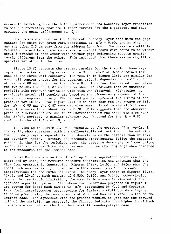
F i g u r e 1 3 ( f ) p r e s e n t s t h e p r e s e n t r e s u l t s f o r t h e t u r b u l e n t boundary- l a y e r case i n t e r m s of each of t h e t h r e e w a l l c o n t o u r s . The r e s u l t s i n f i g u r e 1 3 ( f ) are s i m i l a r f o r each w a l l contour except f o r t h e a p p a r e n t o r d e r l y dependence on w a l l contour a t xIc = 0.80 and 0.88. A t t h e x / c = 0.7 l o c a t i o n , t h e dashed l i n e between t h e two p o i n t s f o r t h e 0.87 contour i s shown t o i n d i c a t e t h a t an uns teady p e r i o d i c - l i k e p r e s s u r e v a r i a t i o n w i t h t i m e w a s observed. (Otherwise, as p r e v i o u s l y n o t e d , a l l r e s u l t s are based on t h e t ime-steady segment of t h e t r a n s d u c e r response c u r v e . ) The two end p o i n t s r e p r e s e n t t h e l i m i t s of t h e p r e s s u r e v a r i a t i o n . From f i g u r e 9(d) i t i s s e e n t h a t t h e shock-wave p r o f i l e f o r M2 = 0.85 and t h e 0.87 c o n t o u r , when e x t r a p o l a t e d t o t h e a i r f o i l sur - f a c e , i n t e r s e c t s i t a t about x / c = 0.70. This s u g g e s t s t h a t t h e observed p r e s s u r e f l u c t u a t i o n s are due t o an u n s t e a d i n e s s i n t h e shock p o s i t i o n n e a r t h e a i r f o i l s u r f a c e . A s i m i l a r behavior w a s observed f o r t h e M = 0.85 contour i n t h e v i c i n i t y of
C p vs x / c f o r a Mach number of 0.85 o b t a i n e d f o r
M2 = 0.83.
The r e s u l t s i n f i g u r e 13 , when compared t o t h e cor responding r e s u l t s i n f i g u r e 1 2 , show agreement w i t h t h e w e l l - e s t a b l i s h e d f a c t t h a t t u r b u l e n t a i r - f o i l boundary l a y e r s s e p a r a t e f a r t h e r downstream on t h e a i r f o i l t h a n do l a m i - n a r boundary l a y e r s . F u r t h e r , t h e p r e s s u r e d i s t r i b u t i o n s f o l l o w t h e expec ted p a t t e r n i n t h a t f o r t h e t u r b u l e n t c a s e , t h e p r e s s u r e d e c r e a s e s t o lower v a l u e s on t h e a i r f o i l and e x h i b i t s h i g h e r v a l u e s n e a r t h e t r a i l i n g edge when compared t o t h e p r e s s u r e s f o r t h e laminar case.
Loca l Mach numbers on t h e a i r f o i l up t o t h e s e p a r a t i o n p o i n t can be e s t i m a t e d by u s i n g t h e measured p r e s s u r e d i s t r i b u t i o n and assuming t h a t t h e f low from upstream i s i s e n t r o p i c . F i g u r e s 1 4 ( a ) , l 4 ( b ) , and 1 4 ( c ) show t h e l o c a l Mach numbers vs x / c computed i n t h i s manner from t h e p r e s s u r e d i s t r i b u t i o n s f o r t h e t u r b u l e n t a i r f o i l boundary-layer cases i n f i g u r e s 1 3 ( c ) , 1 3 ( d ) , and 1 3 ( e ) a t Mach numbers of 0.830, 0.850, and 0.870, r e s p e c t i v e l y . Due t o t h e i s e n t r o p i c l i m i t a t i o n , t h e computat ions w e r e t e r m i n a t e d a t t h e a p p a r e n t s e p a r a t i o n p o i n t . A l s o shown f o r comparison purposes i n f i g u r e 1 4 are c u r v e s f o r l o c a l Mach number vs x / c determined by Wood and Gooderum from t h e i r i n t e r f e r o m e t e r measurements f o r laminar a i r f o i l boundary l a y e r s . A s n o t e d p r e v i o u s l y , t h e measurements of Wood and Gooderum w e r e l i m i t e d t o t h e l a m i n a r case. The agreement w i t h t h e p r e s e n t r e s u l t s is good f o r t h e forward h a l f of t h e a i r f o i l . A s expec ted , t h e f i g u r e s i n d i c a t e t h a t h i g h e r l o c a l Mach numbers are reached f o r t h e t u r b u l e n t a i r f o i l boundary-layer case.
15
I
I I I II I I I II 1111 11111 II II m11 II 1111111111 II I
CONCLUDING REMARKS
R e s u l t s of t h i s s t u d y demonst ra te t h a t two-dimensional t r a n s o n i c a i r f o i l f lows s i m i l a r t o t h o s e observed i n wind t u n n e l s can b e g e n e r a t e d i n shock t u b e s when tes t s e c t i o n w a l l c o n t o u r i n g is employed. S c h l i e r e n photos and o t h e r measurements show t h a t t h e f lows produced i n t h e t e s t s e c t i o n are v e r y uniform and f r e e of t u r b u l e n c e . Thus, a i r f o i l t e s t i n g can b e accomplished i n f lows t h a t are r e l a t i v e l y d i s t u r b a n c e - f r e e when compared t o some wind-tunnel f lows. A n a l y s i s of shock-tube performance p r e d i c t s t h a t t r a n s o n i c a i r f o i l f lows w i t h v e r y h i g h chord Reynolds numbers can b e genera ted . Although t h e p r e s e n t s t u d y w a s l i m i t e d t o a maximum chord Reynolds number o f 2x10⁶, t h e r e appears t o b e no r e a s o n why v e r y h i g h Reynolds number f lows could n o t b e gen- e r a t e d i n p r a c t i c e . The l a r g e shock t u b e d e s c r i b e d i n r e f e r e n c e 15 and l o c a t e d a t t h e NASA A m e s Research Center i s s u i t a b l e f o r producing such f lows.
Although t h e r e s u l t s o b t a i n e d are somewhat s e n s i t i v e t o w a l l c o n t o u r , t h e requirement f o r w a l l contour ing i n s h o c k - t u b e - a i r f o i l t e s t i n g i s n o t viewed as a s e r i o u s l i m i t a t i o n . T h i s i s e s p e c i a l l y t r u e where r e s u l t s from such tes t : are t o b e used t o check a n a l y t i c a l t e c h n i q u e s t h a t can accommodate e f f e c t s of t h e w a l l .
Ames Research Center N a t i o n a l Aeronaut ics and Space A d m i n i s t r a t i o n
M o f f e t t F i e l d , C a l i f . , 94035, A p r i l 1 9 , 1978
16
APPENDIX A
SHOCK-TUBE PERFORMANCE CONSIDERING VARIABLE SPECIFIC HEATS
The shock t u b e performance curves i n f i g u r e 2 assume i d e a l g a s behavior and c o n s t a n t s p e c i f i c h e a t s . These assumptions are v a l i d f o r t h e case of a i r as t h e test g a s , b u t may n o t b e a c c e p t a b l e f o r t h e m i x t u r e s cons idered . The i n f l u e n c e of t h e assumptions f o r t h e argon-carbon d i o x i d e m i x t u r e h a s been cons idered and i s d i s c u s s e d below. Before t e s t i n g is c a r r i e d o u t u s i n g t h e a rgon Freon-12 m i x t u r e t h e above assumptions should b e f u r t h e r e v a l u a t e d .
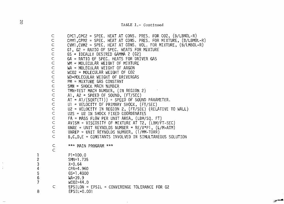
The assumption of t h e i d e a l gas e q u a t i o n of s t a t e p = pRu/(m)T is cons idered adequate f o r t h e c o n s t i t u e n t s of t h e argon-carbon d i o x i d e mixture . I n a d d i t i o n , t h e s p e c i f i c h e a t s of a rgon are c o n s t a n t over a wide range of tempera ture . However, t h e s p e c i f i c h e a t s of carbon d i o x i d e e x h i b i t r e l a t i v e l y pronounced v a r i a t i o n s w i t h tempera ture . It i s cons idered impor tan t t o m a i n t a i n t h e s p e c i f i c h e a t r a t i o y2 e q u a l t o 1 . 4 0 . Thus, i t is n e c e s s a r y t o de te rmine f o r t h e case of v a r i a b l e s p e c i f i c h e a t s t h e mole f r a c t i o n of a rgon and t h e v a l u e of M, t h a t w i l l produce t h e d e s i r e d M, w i t h y2 5 1 . 4 0 . A computer program w a s w r i t t e n t o c a r r y o u t t h e n e c e s s a r y computat ions. The f low c h a r t f o r t h e program i s shown i n f i g u r e 15 . A complete l i s t i n g of t h e program i s p r e s e n t e d i n t a b l e 1.
F i g u r e 1 6 p r e s e n t s a comparison of some of t h e r e s u l t s o b t a i n e d u s i n g t h e computer program w i t h cor responding r e s u l t s o b t a i n e d by assuming c o n s t a n t s p e c i f i c h e a t s . The c u r v e x v s Ms ( long dashes) w a s o b t a i n e d u s i n g t h e computer program and imposing t h e c o n d i t i o n y1 # 1 .40 . ) Also shown is t h e v a l u e x = 0.52 o b t a i n e d from t h e c o n s t a n t s p e c i f i c h e a t s o l u t i o n , t h a t i s , y2 = y1 ( s h o r t d a s h e s ) . Noting t h a t w i t h v a r i a b l e s p e c i f i c h e a t s , x i s o n l y a weak f u n c t i o n of M,, x w a s f i x e d a t 0.64 ( i . e . , t h e y and Mach number d e c i s i o n s w e r e bypassed i n f i g . 15) and t h e r e s u l t s p r e s e n t e d as s o l i d c u r v e s w e r e o b t a i n e d .
y2 E 1 . 4 0 . ( I n t h i s c a s e
The r e s u l t s f o r M2 v s M, are e s s e n t i a l l y t h e s a m e f o r b o t h c o n s t a n t s p e c i f i c h e a t s (x = 0.52) and v a r i a b l e s p e c i f i c h e a t s (x = 0 . 6 4 ) so o n l y one c u r v e is shown. The q u a n t i t y y2 - 1 i s f o r a l l p r a c t i c a l purposes e q u a l t o 0.40 when x i s t a k e n as 0.64 . For c o n s t a n t s p e c i f i c h e a t s t h e s o n i c v e l o c i t y a = 1 6 . 6 6 m / s e c , and f o r v a r i a b l e s p e c i f i c h e a t s a = 17.08 T 1 1 2 m / s e c , where T i s i n d e g r e e s Kelvin.
Although t h e d i f f e r e n c e s between t h e v a r i a b l e and c o n s t a n t s p e c i f i c h e a t r e s u l t s and c u r v e s a re n o t l a r g e , t h e i n f l u e n c e of t h e d i f f e r e n c e on t h e f low v a r i a b l e s i s n o t n e c e s s a r i l y n e g l i g i b l e . This i s b e s t i l l u s t r a t e d by a numeri- c a l example. Consider a shock-tube test planned and c a r r i e d o u t f i r s t on t h e b a s i s of t h e c o n s t a n t s p e c i f i c h e a t s o l u t i o n and second on t h e b a s i s o f t h e , v a r i a b l e s p e c i f i c h e a t s s o l u t i o n . L e t t h e d e s i r e d t e s t Mach number M, b e 0.877 f o r each case and l e t t h e r e s u l t s o b t a i n e d f o r b o t h cases. I n s p e c t i o n of t h e r e s u l t s , p a r t i c u l a r l y
T, = 297 K. T a b l e 2 p r e s e n t s a comparison of
1 7
those for Us, indicates that significant errors would be introduced by assuming constant specific heats f o r carbon dioxide in the argon-carbon dioxide mixture.
18
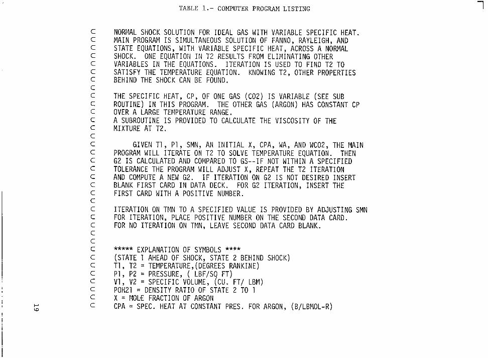
TABLE 1.- COMPUTER PROGRAM LISTING 7
C C C C C C C C C C C C C C C C C C C C C C C C C C C C C C C C C C C
NORi'4AL SHOCK SOLUTION FOR I D E A L GAS WITH VARIABLE S P E C I F I C HEAT. M A I N PROGRAM I S SIMULTANEOUS SOLUTION OF FANNO, RAYLEIGH, AND STATE EQUATIONS , WITH VARIABLE S P E C I F I C HEAT, ACROSS A NORMAL SHOCK. VARIABLES I N THE EQUATIONS. SATISFY THE TEMPERATURE EQUATION. BEHIND THE SHOCK CAN BE FOUND.
ONE EQUATION 114 T 2 RESULTS FROM E L I M I N A T I N G OTHER ITERATION I S USED TO F I N D T 2 TO
KNOWING T 2 , OTHER PROPERTIES
THE SPECIFIC HEAT, CP, OF ONE GAS ( ~ 0 2 ) IS VARIABLE (SEE SUB ROUTINE) I N T H I S PROGRAM. OVER A LARGE TEMPERATURE RANGE. A SUBROUTINE I S PROVIDED TO CALCULATE THE V ISCOSITY OF THE MIXTURE AT T 2 .
THE OTHER GAS (ARGON) HAS CONSTANT CP
GIVEN T1, P l y SMN, AN I N I T I A L X, CPA, WAY AND WCO2, THE M A I N PROGRAM WILL ITERATE ON T 2 TO SOLVE TEMPERATURE EQUATION.
TOLERANCE THE PROGRAM WILL ADJUST X, REPEAT THE T 2 ITERATION AND COMPUTE A NEW G2. I F ITERATION ON G2 I S NOT DESIRED INSERT BLANK F I R S T CARD I N DATA DECK. FOR 62 ITERATION, INSERT THE F I R S T CARD WITH A P O S I T I V E NUMBER.
THEN G2 I S CALCULATED AND COMPARED TO G S - - I F NOT W I T H I N A S P E C I F I E D
ITERATION ON TMN TO A S P E C I F I E D VALUE I S PROVIDED BY ADJUSTING SMN FOR ITERATION, PLACE P O S I T I V E NUMBER ON THE SECOND DATA CARD. FOR NO ITERATION ON TMN, LEAVE SECOND DATA CARD BLANK.
***** EXPLANATION OF SYMBOLS **** (STATE 1 AHEAD OF SHOCK, STATE 2 BEHIND SHOCK) T 1 , T2 = TEMPERATURE, (DEGREES RANKINE) P1 , P 2 = PRESSURE, ( LBF/SQ F T ) V1 , V2 = S P E C I F I C VOLUME, (CU. FT/ LBM) POH21 = DENSITY RATIO OF STATE 2 TO 1 X = MOLIE FRACTION OF ARGON CPA = SPEC. HEAT AT CONSTANT PRES. FOR ARGON, (B/LBMOL-R)
10 0 TABLE 1.- Continued
C C C C C C C C C C C C C C C C C C C C C C C
C C
C 8
c p c i , C P C ~ = SPEC. HEAT AT CONS. PRES. FOR cozy (B/LBMOL-R)
c v M i ,CVMZ = SPEC. HEAT AT CONS. VOL. FOR MIXTURE, (BILMBOL-R) CPMl ,CPM2 = SPEC. HEAT A T CONS. PRES. FOR MIXTURE, (B/LBMOL-R)
G1, 62 = R A T I O OF SPEC. HEATS FOR MIXTURE GS = I D E A L L Y DESIRED GAMMA 2 (62) 64 = R A T I O OF SPEC. HEATS FOR DRIVER GAS WM = MOLECULAR WEIGHT OF MIXTURE WA = MOLECULAR WEIGHT OF ARGON WC02 = MOLECULAR WEIGHT OF C 0 2 WD=MOLECULAR WEIGHT OF DRIVERGAS PM = MIXTURE GAS CONSTANT SMN = SHOCK MACH NUMBER TMN=TEST MACH NUMBER, ( I N REGION 2 ) A1 , A 2 = SPEED OF SOUND, (FT /SEC) AT = AI/(SQRT(TI)) = SPEED OF SOUND PARAMETER. U1 = VELOCITY OF PRIMARY SHOCK, (FT /SEC) U 2 = VELOCITY I N REGION 2, ( F T / S E C ) ( R E L A T I V E TO WALL) U2S = U 2 I N SHOCK F I X E D COORDINATES FA = MASS FLOW PER U N I T AREA, (LBM/SQ. F T )
UNREP = U N I T REYNOLDS NUMBER, (1 /MM-TORR) B,C,D,E = CONSTANTS INVOLVED I N SIMULTANEOUS SOLUTION
A V I S M = V I S C O S I T Y OF MIXTURE A T T2, UNRE = U N I T REYNOLDS NUMBER = RE/X*Pl ,
(LBM/FT-SEC) (L/M-ATP.I)
*** M A I N PROGRAM *** P 1 = 1 0 0 . 0 SMN=1 .735 X=O. 64 CPA=4.960 G S = l . 4 0 0 0 WA=39.9 WC02=44.0 EPSILON = E P S I L = CONVERENGE TOLERANCE FOR 62 EPS I L=O. 001
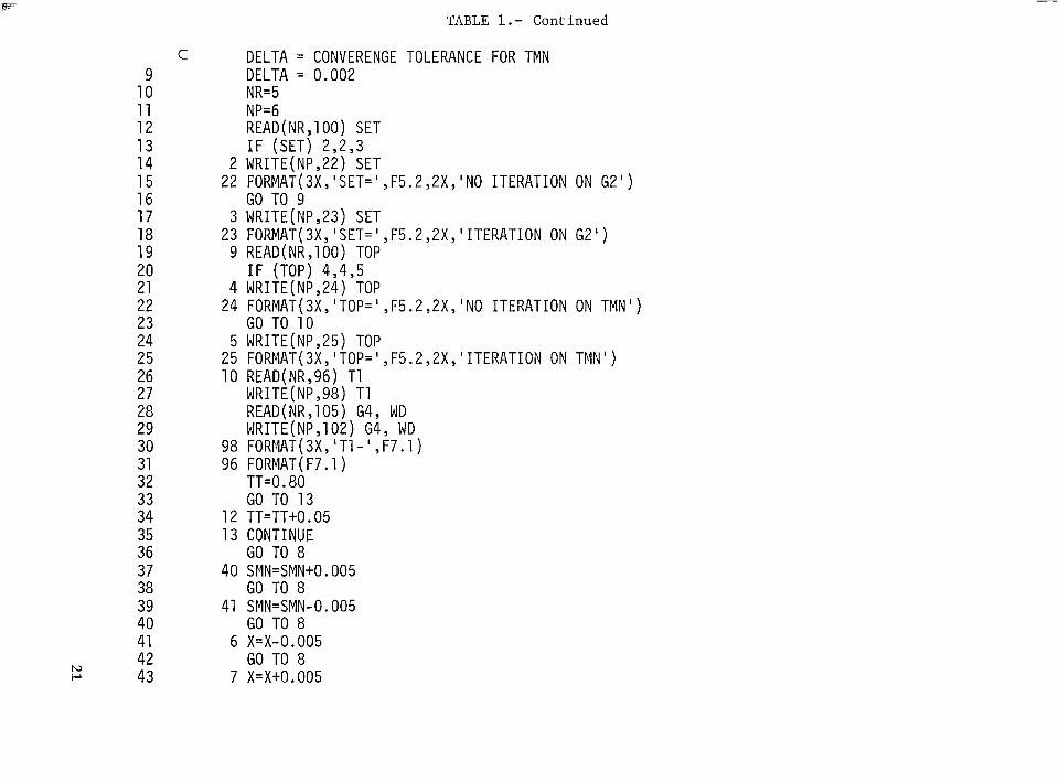
TABLE 1.- Continued
C DELTA = CONVERENGE TOLERANCE FOR TMN 9 DELTA = 0.002 10 NR=5 11 NP=6 12 READ(NR,100) SET 13 IF (SET) 2,2,3 14 2 WRITE(NP,22) SET 15 16 GO TO 9 17 3 WRITE(NP,23) SET 18
20 IF (TOP) 4,4,5 21 4 WRITE(NP,24) TOP 22 23 GO TO 10 24 5 WRITE(NP,25) TOP 25 26 10 READ(NR,96) T1 27 WRITE(NP,98) T1 28 READ(NR,105) 64, WD 29 WRITE(NP,102) G4, WD
31 96 FORMAT ( F7.1) 32 TT=O. 80 33 GO TO 13 34 12 TT=TT+O. 05 35 13 CONTINUE 36 GO TO 8 37 40 SMN=SMN+O. 005 38 GO TO 8 39 41 SMN=SMN-O.O05 40 GO TO 8 41 6 X=X-0.005 42 GO TO 8 43 7 x=x+o.o05
22 FORMAT(3XY'SET=' ,F5.2,2XY'NO ITERATION ON G2')
23 FORMAT(3X, 'SET=' ,F5.2,2XY'ITERATION ON 62') 19 9 READ(NR,IOO) TOP
24 FORMAT(3XY'TOP=' ,F5.2,2XY'NO ITERATION ON TMN')
25 FORMAT(3X, 'TOP=' ,F5.2,2XY 'ITERATION ON TMN')
30 98 FORMAT(3XY'T1-' ,F7.1)
h) I-'
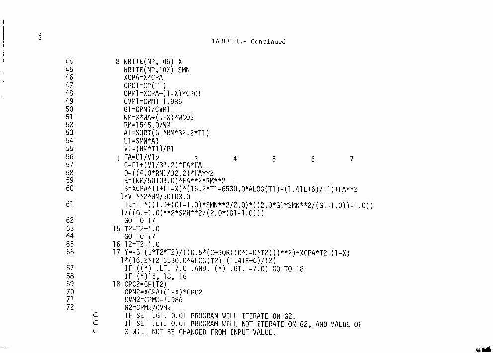
TABLE 1.- Continued
44 45 46 47 48 49 50 51 52 53 54 55 56 57 58 59 60
61
62 63 64 65 66
67 68 69 70 71 72
WRITE(NPy1O6) X WRITE(NP,107) SMN XCPA=X*CPA CPCl =CP( T1) CPMl =XCPA+( 1 -X)*CPCl CVMl =CPMl- 1 .986
WM=X*WA+( 1 -X)*WCO2 RM=1545.O/WM
G1 =CPM1 /CVMl
A1 =SQRT( G1 *RM*32.2*Tl) U1 =SMN*Al VI=(RM*TI )/PI FA=U1 /V12 3 4 5 6 7 C=Pl+( V1/32.2)*FA*FA D=((4.0*RM)/32.2)*FA**2 E=(WM/50103'. O)*FA**2*RM**2 B=XCPA*T1+(1-X)*(16.2*T1-653O.O*ALOG(T1)-(1.41 E+6)/Tl)+FA**2
T2=T1*( (1 .O+( Gl-l.O)*SMN*"2/2.0)*( (2.O*G1 *SNN**2/ (Gl-1 .O) )-1 .O) ) 1 *V1**2*WM/50103.0
1/ ( (Gl+l. 0)**2*SMN**2/ (2.O*(G1-1.0))) GO TO 17
GO TO 17 15 T2=T2+1 .O
16 T2=T2-1.0 17 Y=-B+( E*T2*T2)/ ( (0.5*( C+SQRT( C*C-D*T2) ) )**2)+XCPA*T2+( 1 -X)
1 *( 16.2*T2-6530.O*ALCG (T2) - (1.41 E+6)/T2) IF ((Y) .LT. 7.0 .AND. (Y) .GT. -7.0) .GO TO 18
18
C C C
IF (Y)15, 18, 16 CPC2=CP (T2) CPM2=XCPA+( 1 -X)*CPC2 CVMZ=CPM2-1.986 G 2 = C P M 2 / C V P.12 IF SET .GT. 0.01 PROGRAM WILL ITERATE ON 62. IF SET .LT. 0.01 PROGRAM WILL NOT ITERATE ON 62, AND VALUE OF X WILL NOT BE CHANGED FROM INPUT VALUE.
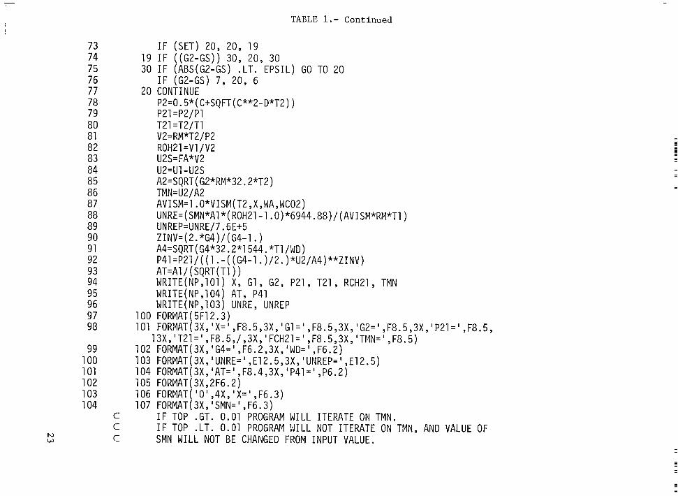
TABLE 1.- Continued
73 74 75 76 77 78 79 80 81 82 83 84 85 86 87 88 89 90 91 92 93 94 95 96 97 98
99 100 101 102 103 104
h) w
I F (SET) 20, 20, 19 19 I F ((G2-GS)) 30, 20, 30 30 I F (ABS(G2-GS) .LT. EPSIL) GO TO 20
I F (G2-GS) 7, 20, 6 20 CONTINUE
P2=0.5*( C+SQFT( C**2-D*T2) ) P21 =P2/P1 T21 =T2/T1 V2=RM*TZ/P2 ROH21 =V1 /V2 U2S=FA*V2 u2=u1 -u2s A2=SQRT( G2*RM*3Z92*T2) TM N = U 2 / A2 AVISM=l . O*VISM( T2 , X , WA, WCO2 )
UNREP=UNRE/7.6E+5
A4=SQRT( G4*32.2*1544. *T1 /WD)
AT=Al/ (SQRT( T1) ) WRITE(NP,101) X, G1, 62, P21 , T21 , RCH21 , TblN WRITE(NP,104) AT, P41 WRITE( NP, 103) UNRE , UNREP
UNRE=(SMN*Al*(ROH21-1.0)*6944.88)/(AVISM*RM*Tl)
ZINV=( 2. *G4)/ ( G4-1. )
P41=P21/( ( 1 . - ( (64-1 .)/2.)*U2/A4)**ZINV)
100 FORblAT(5F12.3) 101 FORMAT(3X, 'X= ' ,F8.5,3XY 'G1=' ,F8.5,3XY 'G2=' ,F8.5,3XY'P21=' ,F8.5,
102 FORMAT( 3X, 'G4= ' ,F6.2,3X , ' WD= ' , F6.2) 103 FORMAT( 3X, ' UNRE= ' , E l 2.5,3X, 'UNREP= ' , E l 2 .5) 104 FORMAT(3XY'AT=' ,F8.4,3XY'P41=' ,P6.2) 1 0 5 FORMAT ( 3 X , 2 F 6.2 ) 106 FORMAT( ' 0 ' ,4X, ' X = ' ,F6.3) 107 FORMAT( 3X , 'SMN= , F6.3)
C I F TOP .GT. 0.01 PROGRAM WILL ITERATE ON TMN. C I F TOP .LT. 0.01 PROGRAM !?JILL NOT ITERATE ON TMN, AND VALUE OF C SMN WILL NOT BE CHANGED FROM INPUT VALUE.
13X, IT21 = ' , F8.5 ,/ ,3X, ' FCH21= ' , F8.5,3X, 'TMN= ' , F8.5)
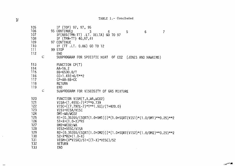
TABLE 1.- Concluded
105 106 107 108 109 110 111 112
C
113 114 115 116 117 118 119
C
120 121 122 123 124 125 126 127 128 129 130 131 132 133
95
97
99
IF (TOP) 97, 97, 95 CONTI NUE2 3 4 5 6 7 IF(ABS(TMN-TT) .LT. DELTA) GO TO 97 IF (TMN-TT) 40,97,41 CONTINUE IF (TT .LT. 0.86) GO TO 12 STOP END SUBPROGRAM FOR SPECIFIC HEAT OF C02 (JONES AND HAWKINS)
FUNCTION CP (T) AA=16.2 BB=6530.O/T CC=1.41 E+6/T**2
RETURN END SUBPROGRAM FOR VISCOSITY OF GAS MIXTURE
CP=AA-BB+CC
FUNCTION VISM( T , X ,WA , WCO2) VISA=( 1.451 E-7)*T**O. 739 VISC=( (7.792E-7)*T**1.50)/(T+420.0) VISl =VISA/VISC DM1 =WA/WC02 R1= (0.35355/ (SQRT( 1 . O+DMl) ) )*( 1 .O+SQRT( VISl )*( 1 . O/DMl )**O. 25)**2 Sl=X+(l .O-X)*R1 DMZ=WCOZ/WA VISZ=VISC/VISA R2= (0.35355/ (SQRT( 1 . O+DM2) ) ) * ( 1 . O+SQRT ( VIS2) * ( 1 . O/DM2) **O. 25) **2 S2=X*R2+( 1 .O-X) VISM=( X*VISA)/Sl+( (l-X)*VISC)/S2 RETURN END
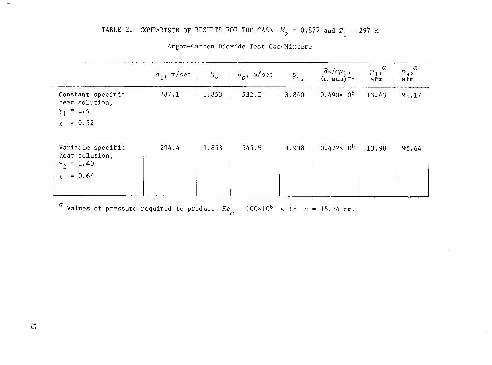
TABLE 2.- COMPARISON OF RESULTS FOR THE CASE M, = 0.877 and T, = 297 K
Argon-Carbon Dioxide Test GasIMixture
Constant s p e c i f i c 287 .1 , 1 .853 , 532.0 a 3.840 , 0 . 4 9 0 ~ 1 0 ~ 13 .43 31.17 h e a t s o l u t i o n , I I
y1 = 1 . 4
x = 0.52
294.4 Var iab le s p e c i f i c
1 I
h e a t s o l u t i o n , y2 = 1.40
1 .853 545.5 3.938 0 . 4 7 2 ~ 1 0 ~ 1 3 . 9 0 95.64
a Values of p re s su re r equ i r ed t o produce Re = 100~10~ wi th e e
L = 15.24 cm.
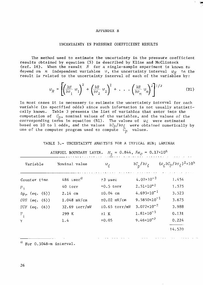
APPENDIX B
UNCERTAINTY I N PRESSURE COEFFICIENT RESULTS
The method used t o estimate t h e u n c e r t a i n t y i n t h e p r e s s u r e c o e f f i c i e n t r e s u l t s o b t a i n e d by e q u a t i o n (5) is d e s c r i b e d by K l i n e and McClintock ( r e f . 1 6 ) . When t h e r e s u l t R f o r a s ingle-sample experiment is known t o depend on n independent v a r i a b l e s V , t h e u n c e r t a i n t y i n t e r v a l WR i n t h e r e s u l t i s r e l a t e d t o t h e u n c e r t a i n t y i n t e r v a l of each of t h e v a r i a b l e s by:
*R = [(qwJ2 + (ZW2)2 a v 2 + . . .
I n most cases i t i s n e c e s s a r y t o estimate t h e u n c e r t a i n t y i n t e r v a l f o r each v a r i a b l e ( t o s p e c i f i e d odds) s i n c e such i n f o r m a t i o n i s n o t u s u a l l y s t a t i s t i - c a l l y known. Table 3 p r e s e n t s t h e l i s t of v a r i a b l e s t h a t e n t e r i n t o t h e computation of cor responding terms i n e q u a t i o n ( B l ) . The v a l u e s of w i w e r e e s t i m a t e d based on 10 t o 1 odds, and t h e v a l u e s use of t h e computer program used t o compute Cp v a l u e s .
CP, nominal v a l u e s of t h e v a r i a b l e s , and t h e v a l u e s of t h e
aCp/av; w e r e o b t a i n e d n u m e r i c a l l y by
TABLE 3.- UNCERTAINTY ANALYSIS FOR A TYPICAL RUN; LAMINAR
AIRFOIL BOUNDARY LAYER. M2 = 0 . 8 4 4 , Re, = 0 . 1 7 ~ 1 0 ~ . . . . . ~= ~ - ._.. ~ - . . ~ ~. . ~
Nominal v a l u e
_ _ _ _ _ - - _ ~ - . ~
486 useca
40 t o r r
2 .14 c m
1 . 0 4 8 mV/cm
32.69 torr/mV
299 K
1 . 4
W i ac /avi P
(W . acP/ avi 2 x 1 ~ 4 2
+3 usee 4 . 0 2 ~ 1 0 - ~ 1 . 4 5 4
20. 5 t o r r 2 . 5 1 ~ 1 0 - ~ 1 . 5 7 5
20. 04 c m 4 . 693x10-1 3 .523
+O. 02 mV/cm 9 . 5 8 5 0 ~ 1 0 - ' 3 .675
20 .65 torr/mV 3 . 0 7 2 ~ 1 0 - ~ 3 .988
+1 K 1 . 8 1 ~ 1 0 - ~ 0 . 1 3 1
20 .05 9 . 4 6 ~ 1 0 - ~ 0 . 2 2 4
~- .
For 0.3048-m i n t e r v a l . a
1 4 . 5 7 0
. ..
26
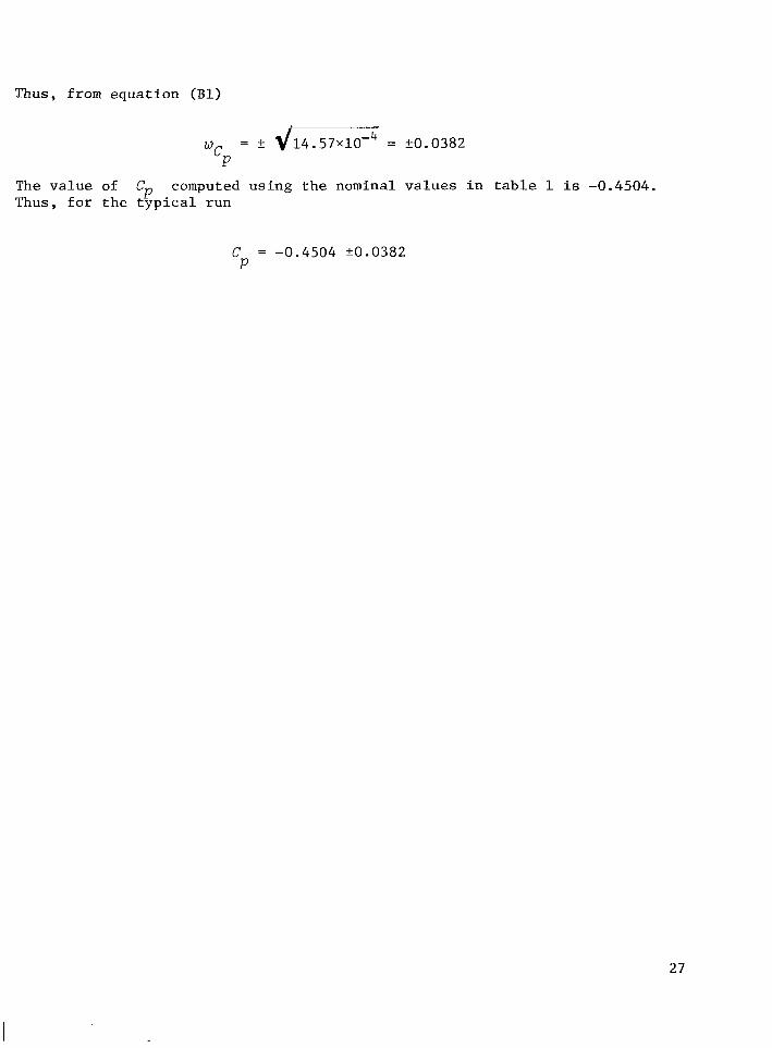
Thus, from e q u a t i o n (Bl)
w = k d 1 4 . 5 7 ~ 1 0 - ~ = k0.0382 cFJ
The v a l u e of Cp Thus, f o r t h e t y p i c a l r u n
computed u s i n g t h e nominal v a l u e s i n t a b l e 1 i s -0.4504.
C = -0.4504 k0.0382 P
27
Y
REFERENCES
1. Alexander, W. K . ; and G r i f f i n , S. A. : Design Study of Basic Models f o r U s e i n t h e Proposed 8 by 10 Foot High Reynolds Number Transonic Wind Tunnel (HIRT) a t Arnold Engineer ing Development Center . AIAA Paper 74-82, AIAA 1 2 t h Aerospace S c i e n c e s Meeting, Washington, D . C . , J a n . 30-Feb. 1, 1974.
2. Kamchi, Jerome S.: N a t i o n a l A e r o n a u t i c a l F a c i l i t i e s Program - t h e Need, t h e F a c i l i t i e s , and t h e Impact. AIAA Paper 74-79, AIAA 1 2 t h Aerospace S c i e n c e s Meeting, Washington, D . C . , J a n . 30-Feb. 1, 1974.
3. Polhamus, E . C . ; K i l g o r e , R. A . ; Adcock, J. B . ; and Ray, E. J . : The Langley Cyrogenic High Reynolds Number Wind-Tunnel Program. & Aeronaut . , v o l . 1 2 , no. 10, O c t . 1974, pp. 30-40.
A s t r o n a u t .
4. Geiger , S. W . ; Mautz, C . N . ; and H o l l y e r , R. N . , Jr . : The Shock Tube as a n Ins t rument f o r t h e I n v e s t i g a t i o n o f Transonic and Supersonic Flow P a t t e r n s . Engineer ing Research I n s t i t u t e Repor t , P r o j e c t M720-4, Univ. of Michigan, 1949.
5. G r i f f i t h , Wayland: Shock-Tube S t u d i e s of Transonic Flow over Wedge P r o f i l e s . J. Aeronaut. S c i . , v o l . 1 9 , no. 4 , Apr. 1952, pp. 249-257.
6. Rueten ik , J. Ray; and Whitmer, Emmet t A.: T r a n s i e n t Aerodynamics of Two- Dimensional A i r f o i l s . WADC T e c h n i c a l Report 54-368, p t . 2 , Wright A i r Development C e n t e r , Wright-Pat terson A i r Force Base, Ohio, Mar. 1958.
7 . Varwig, R. L.; and Rosenman, L. : A 7-Foot-Diameter Shock Tube f o r Transonic and Supersonic Aerodynamic T e s t i n g . J. S p a c e c r a f t , v o l . 3 , no. 12 , Dec. 1966, pp. 1809-1811.
8. Glass, I. I.; and P a t t e r s o n , G. N . : A T h e o r e t i c a l and Experimental Study of Shock-Tube Flows. J. Aeronaut. S c i . , v o l . 22, no. 2 , Feb. 1955, pp. 73-100.
9. Wilke, C . R. : A V i s c o s i t y Equat ion f o r G a s Mixtures . J . of Chem. P h y s i c s , v o l . 18, no. 4 , Apr. 1950, pp. 517-519.
10. Mirels, Harold: Shock Tube T e s t T i m e L i m i t a t i o n due t o Turbulent-Wall Boundary Layer . AIAA J . , v o l . 2 , no. 1, J a n . 1964, pp. 84-93.
11. G o e t h e r t , Bemhard H . : Transonic Wind Tunnel T e s t i n g . Pergamon P r e s s , New York, 1961.
12. Murman, E a r l l M. ; and Cole, J u l i a n D . : C a l c u l a t i o n of P lane Steady Transonic Flows. AIAA J . , v o l . 9 , no. 1, Jan . 1971, pp. 114-121.
13. Murman, E a r l l M.: A n a l y s i s of Embedded Shock Waves C a l c u l a t e d by R e l a x a t i o n Methods. AIAA J . , v o l . 1 2 , no. 5 , May 1974, pp. 626-633.
28
14. Wood, George P.; and Gooderum, Paul B.: Investigation with an Inter- ferometer of the Flow Around a Circular-Arc Airfoil at Mach Numbers Between 0.6 and 0.9. NACA TN 2801, 1952.
15. DeRose, Charles E.: Trim Attitude, Lift and Drag of Apollo Command Module with Offset Center-of-Gravity Positions at Mach Numbers to 29. NASA TN D-5276, 1969.
16. Kline, S. J.; and McClintock, F.: Describing Uncertainties in Single- Sample Experiments. Mech. Eng., vol. 75, no. 1, Jan. 1953, pp. 3-8.
29

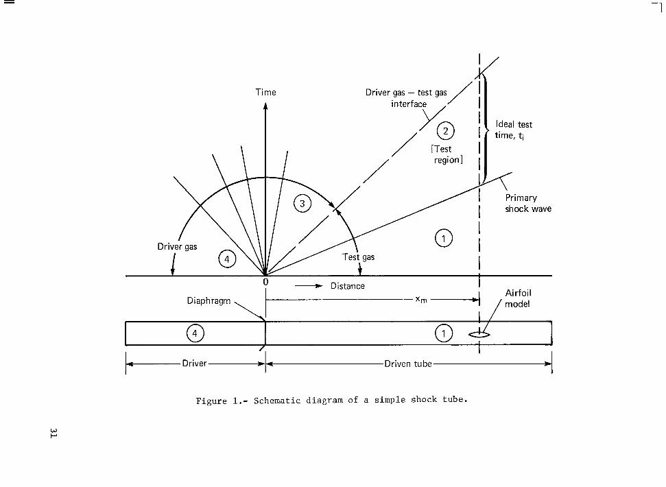
Time interface '
[Test
- Distance I Airfoil
Diaphragm xm /model
@ /
b- Driver-b-Driven tube . Figure 1.- Schematic diagram of a simple shock tube.
w P
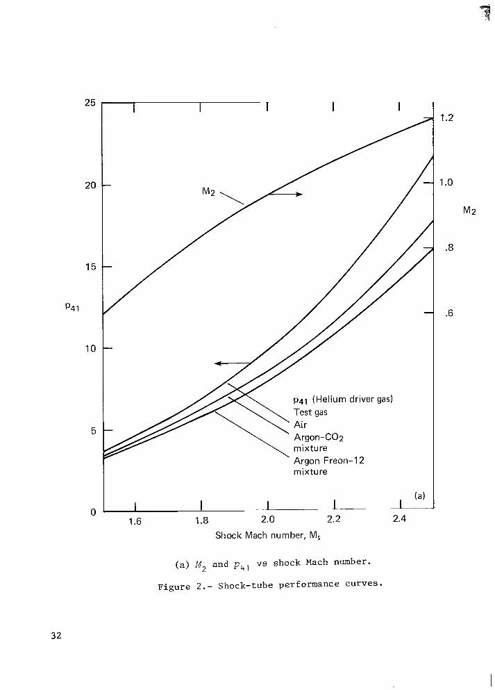
25
20
15
p4 1
10
5
i
p41 (Helium driver gas) Test gas
Argon-CO2 mixture Argon Freon-I 2 mixture
2 1.6 1.8 2.0 2.2 2.4
Shock Mach number, M,
0
( a ) M, and pLtl vs shock Mach number.
F i g u r e 2.- Shock-tube performance curves .
1.2
1 .o
M2
.8
.6
32
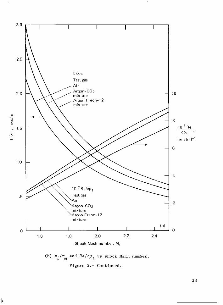
3.0
2.5
2.0
E
% E. 1.5 E ‘1
\ 0
X
+-’
1 .o
.5
0
I I I I I
1 O-’ Re/cpl Test gas
\Argon-COp \Air
mixture Argon Freon-I 2 mixture
1.6 1.8 2.0 2.2 2.4
Shock Mach number, M,
10
8
Re
6
4
2
0
(b) ti/xm and R e l e p l vs shock Mach number.
Figure 2.- Continued.
33
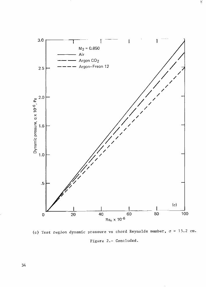
"..
3.0
2.5
2.0 a
?
X a- 2
2
E
n
2 1.5 v)
Q 0 ._ m c >
1 .o
.5
0
- 7- I I 1 M2 = 0.850 Air
-- Argon C 0 2 ---- Argon-Freon 12
20 40 60 Re, x
(c) T e s t r e g i o n dynamic p r e s s u r e vs chord Reynolds
F i g u r e 2.- Concluded.
/ /
/
80 100
number, e = 15.2 cm.
34
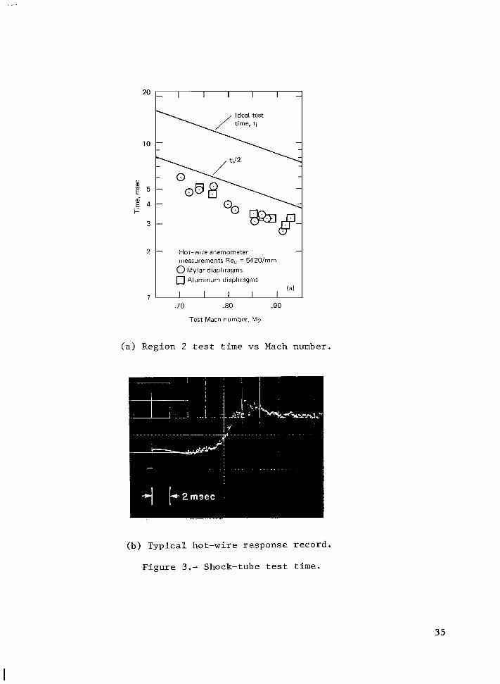
I I I I
10
u 2 5 d E 4
i= 3
1
Hot-wire anemometer measurements Re, = 5420/mm 0 Mylar diaphragms 0 Aluminum diaphragms
.70 .80 .90
Test Mach number, M?
(a) Region 2 t e s t t i m e vs Mach number.
(b) T y p i c a l ho t -wire r e sponse r eco rd .
F i g u r e 3 . - Shock-tube t es t t i m e .
35
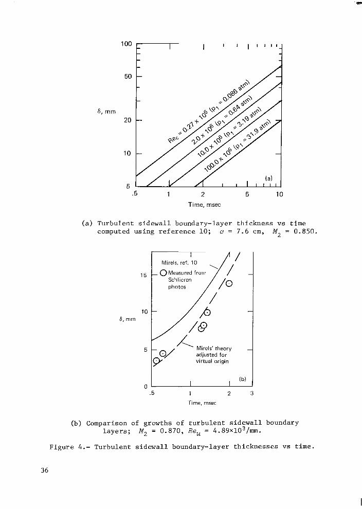
100
50
6 , mm 20
10
5 .5 1 2 5 10
Time, msec
( a ) Turbulent s i d e w a l l boundary-layer t h i c k n e s s vs t i m e computed u s i n g r e f e r e n c e 10; e = 7.6 c m , M, = 0.850.
15
10 F , m m
5
0
/ Mirels, ref. 10
- 0 Measured from
(b) 1 I I
.5 1 2 3
Time, msec
(b) Comparison of growths o f t u r b u l e n t s i d e w a l l boundary l a y e r s ; M, = 0.870, Re, = 4.89x10³/mm.
F i g u r e 4.- Turbulent s i d e w a l l boundary-layer t h i c k n e s s e s vs t i m e .
36
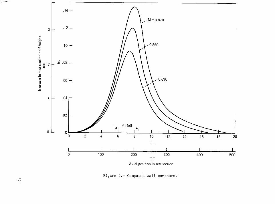
.I4 - n
.I2 - hYM=0*870
.IO - \ b 0 . 8 5 0
.08 -
.06
.04
.02
0
Figure 5.- Computed wall contours .
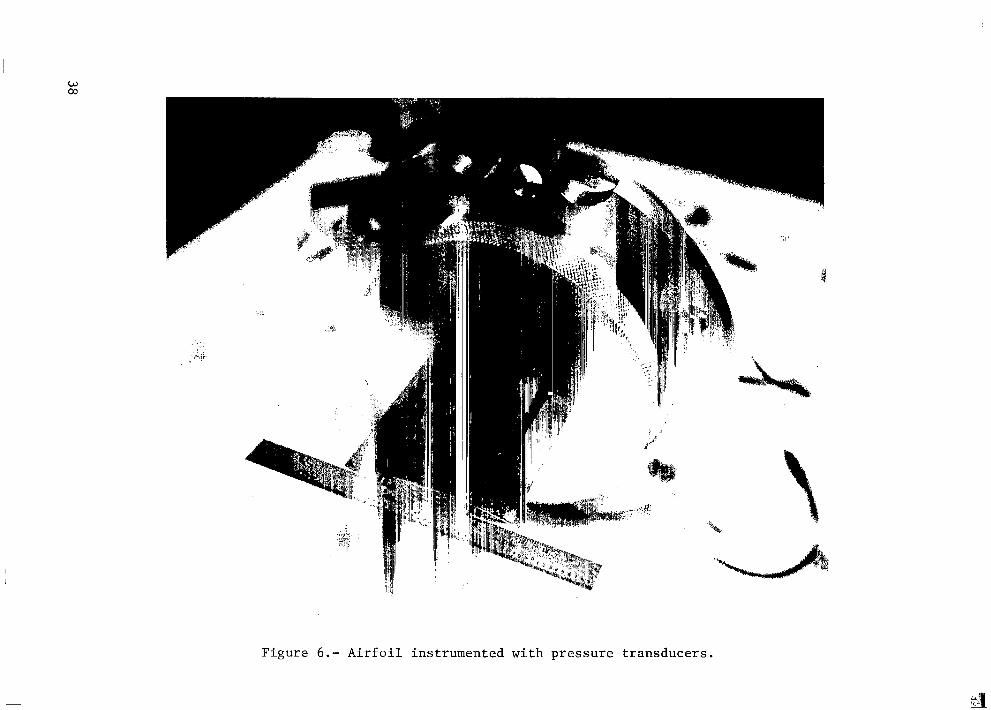
Figure 6.- Airfoil instrumented with pressure transducers.
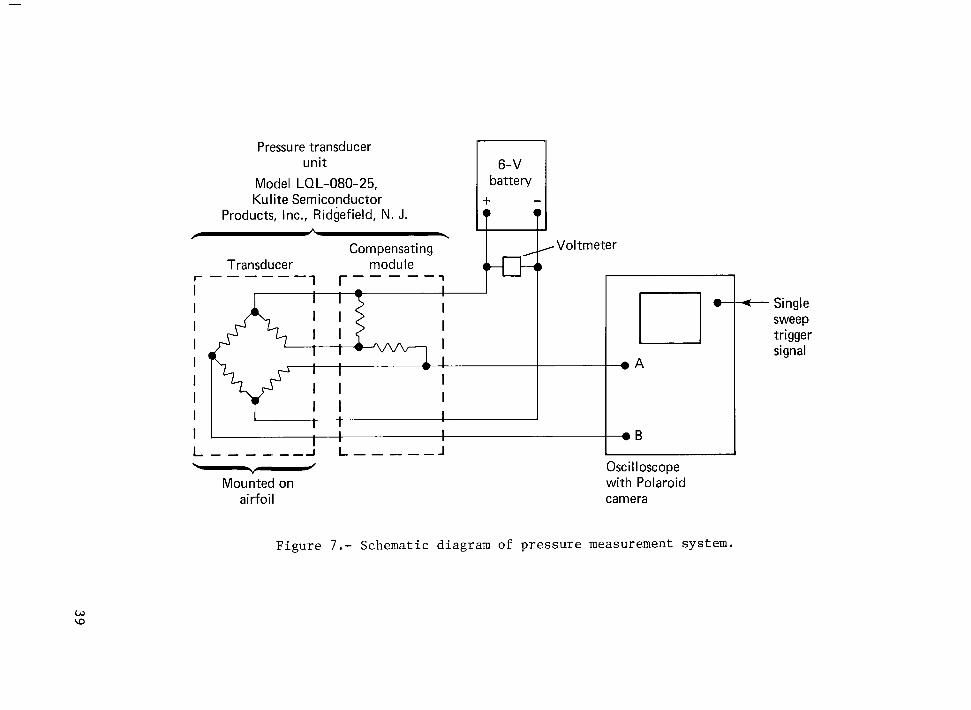
battery
/ L
Volt meter
Pressure transducer unit
Model LQL-080-25, Kulite Semiconductor
Products, Inc., Ridgefield, N. J.
Compensating Transducer module
- -1 -1 r - - - r - - - - -
I
I I L
T I 1 I
I I I I
I
+ Single sweep trigger signal
Figure 7.- Schematic diagram of p re s su re measurement system.
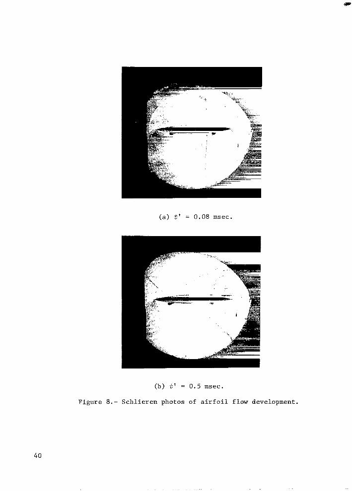
(a) t' = 0.08 m s e c .
(b) t' = 0.5 msec.
F i g u r e 8.- S c h l i e r e n photos of a i r f o i l f l o w development.
40
. . . . .. .. . . . . .. .
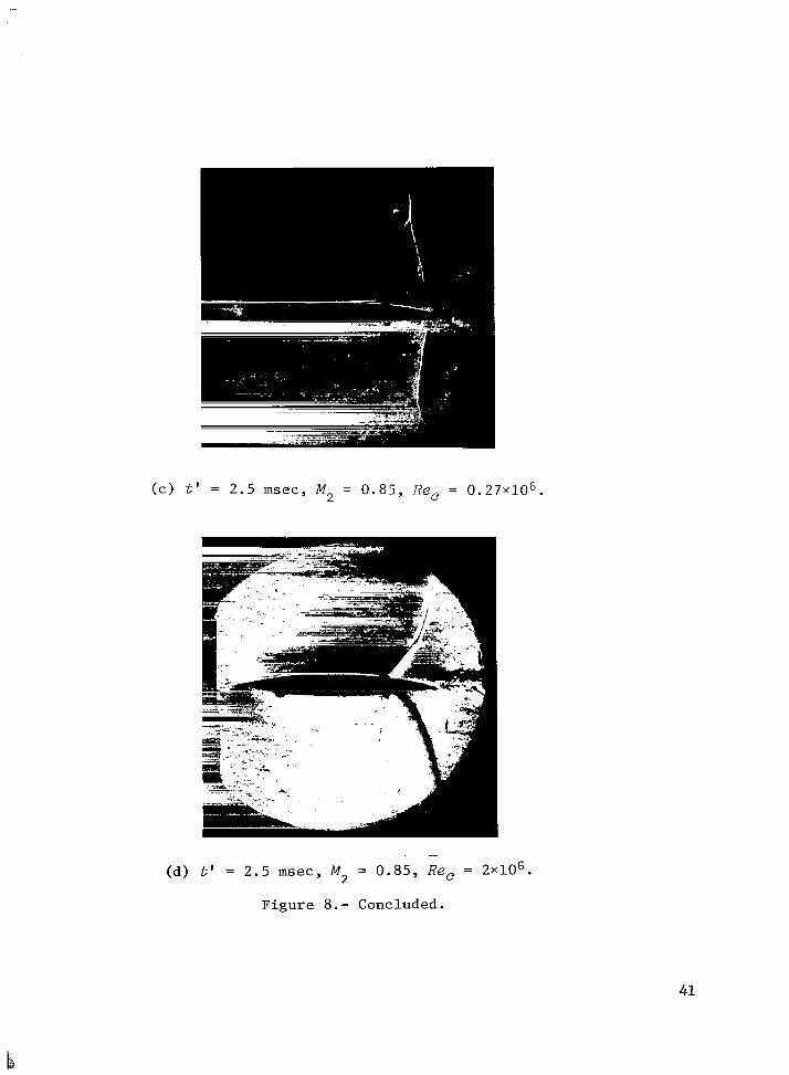
( c ) t' = 2.5 m s e c , M, = 0 . 8 5 , R e , = 0 . 2 7 ~ 1 0 ~ .
. -
(d) t' = 2.5 msec, M = 0.85, R e , = 2 ~ 1 0 ~ . 2
Figure 8.- Concluded.
41
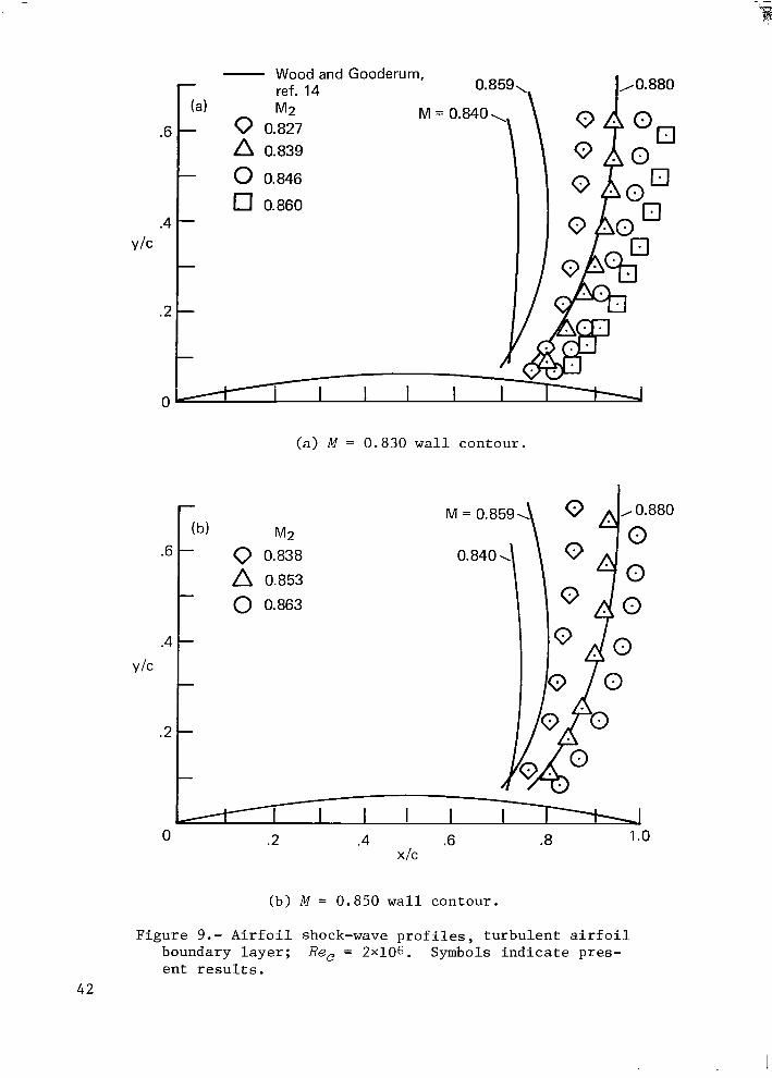
.6
-
(b) M2 - 0 0.838
A 0.853
0 0.863 -
-
-
-
-
.2
0
.6
.4
Y I C
.2
0
- Wood and Gooderum,
( a ) M = 0.830 w a l l contour .
(b) M = 0.850 w a l l contour .
F i g u r e 9.- A i r f o i l shock-wave p r o f i l e s , t u r b u l e n t a i r f o i l boundary l a y e r ; Re, = 2x10⁶. Symbols i n d i c a t e pres - e n t r e s u l t s .
42
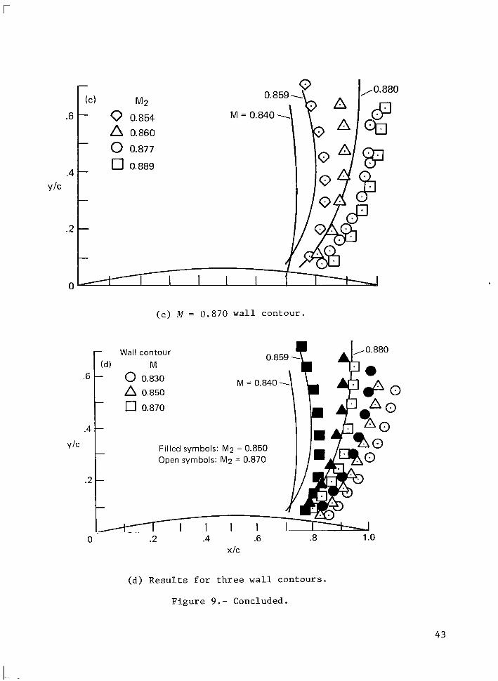
r
.6
.4
V/C
.2
0
(C) M2
- 0 0.854
A 0.860
- 0 0.877
- 0 0.889
0*85g+ A M = 0.840 1’
( c ) M = 0.870 w a l l contour .
I 0.859 - Wall contour
0 0.830 M M = o . ~ ~ o \ \ \ 0.850
.6 pd) t I7 0.870
N O . 880
C P 00
.4 I- Filled symbols: M2 = 0.850 Open symbols: M 2 = 0.870
. I I I I I I 0 .2 .4 .6 .8 1 .o
X I C
(d) R e s u l t s f o r t h r e e w a l l c o n t o u r s .
F i g u r e 9.- Concluded.
4 3
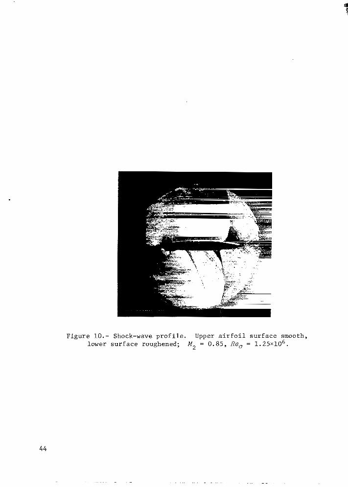
F i g u r e 10.- Shock-wave p r o f i l e . Upper a i r f o i l s u r f a c e smooth, lower s u r f a c e roughened; M, = 0 . 8 5 , Re, = 1 . 2 5 ~ 1 0 ~ .
44
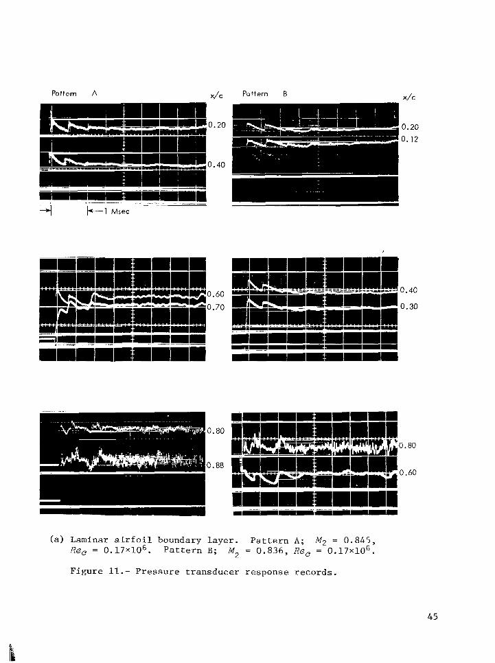
x / C Pattern A Puffern B x / c
3.60
3.70
0.80
0.60
(a ) Laminar a i r f o i l boundary l a y e r . P a t t e r n A; M2 = 0 . 8 4 5 , M, = 0 . 8 3 6 , Re, = 0 . 1 7 ~ 1 0 ~ . Re, = 0.17~10~.
F i g u r e 11.- P r e s s u r e t r a n s d u c e r r e s p o n s e r e c o r d s .
P a t t e r n B;
45
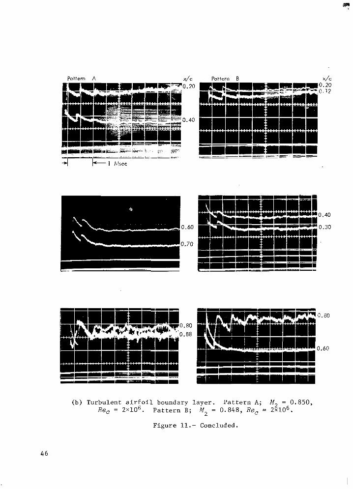
Pattern A Pattern B
I 80 ,88
0.80
0.60
(b) Turbulent a i r f o i l boundary l a y e r . P a t t e r n A; M, = 0.850, Re, = 2 ~ 1 0 ~ . P a t t e r n B; M = 0 .848 , R e , = 2x10⁶.
F i g u r e 11. - Concluded.
2
46
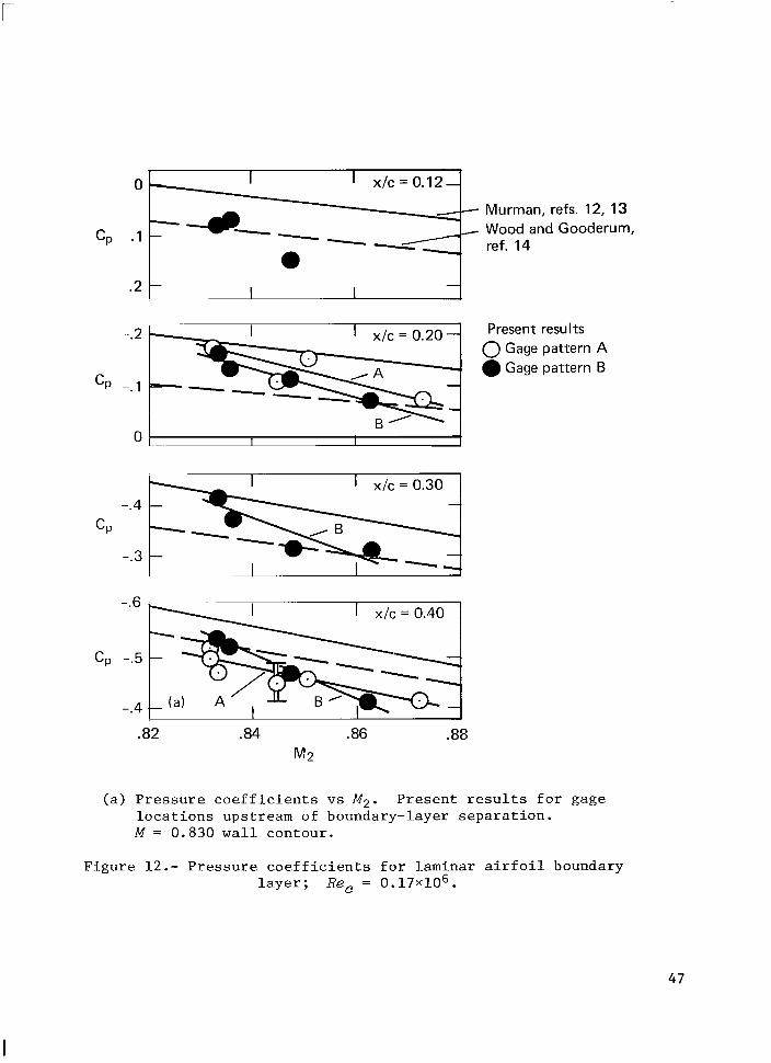
0 . I I x l c = 0.12-
- Murman, refs. 12, 13 - Wood and Gooderum, cp .1 :-- ref. 14
CP
-***I x l c = 0.20
-- -. 1 -- B'
Present results 0 Gage pattern A
Gage pattern B
" , 1 I I
I I I
I 1 x / c = 0.40 -.6
-*4 - (a)
.82 .84 .86 .88 M2
( a ) P r e s s u r e c o e f f i c i e n t s vs M,. P r e s e n t r e s u l t s f o r gage l o c a t i o n s upstream of boundary-layer s e p a r a t i o n . M = 0.830 w a l l contour .
F i g u r e 12.- P r e s s u r e c o e f f i c i e n t s f o r laminar a i r f o i l boundary l a y e r ; R e , = 0.17~10~.
47
I
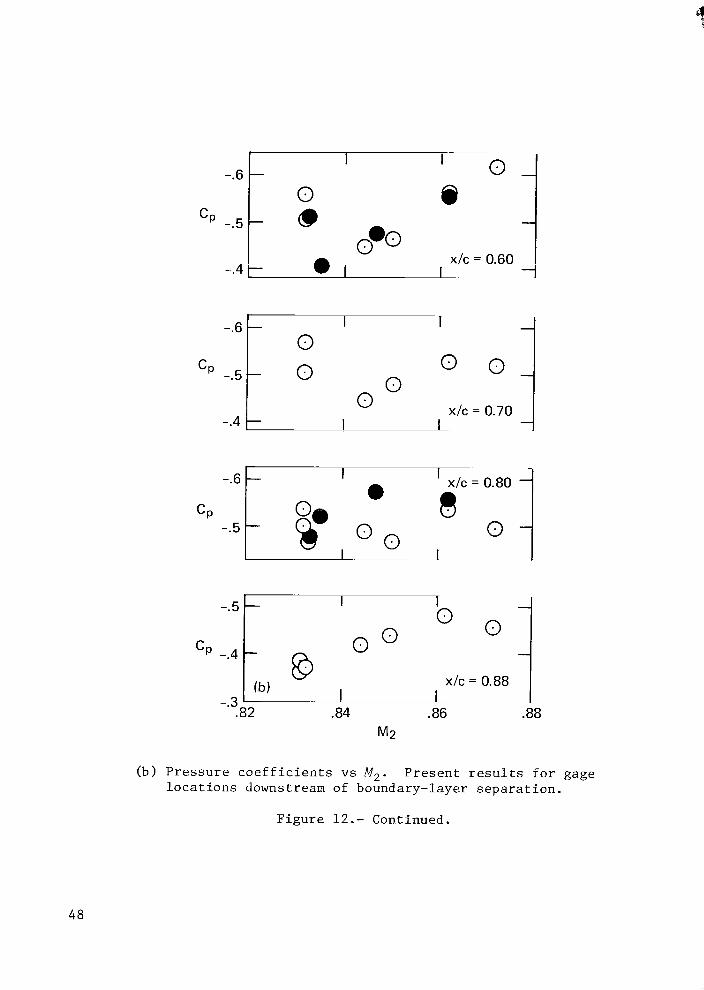
t e 0.0 cp -.5
a r I -.4 I-
0 t o 0 cp -.5
-.4 u
-.5 7 CP
x lc = 0.60 1
x/c = 0.70 _L
’ x l c = 0.80 4
I
~
I
O 01
1 x l c = 0.88 _L .86 .88
(b) P r e s s u r e c o e f f i c i e n t s vs M,. P r e s e n t r e s u l t s f o r gage l o c a t i o n s downstream of boundary-layer s e p a r a t i o n .
F i g u r e 12 . - Continued.
48
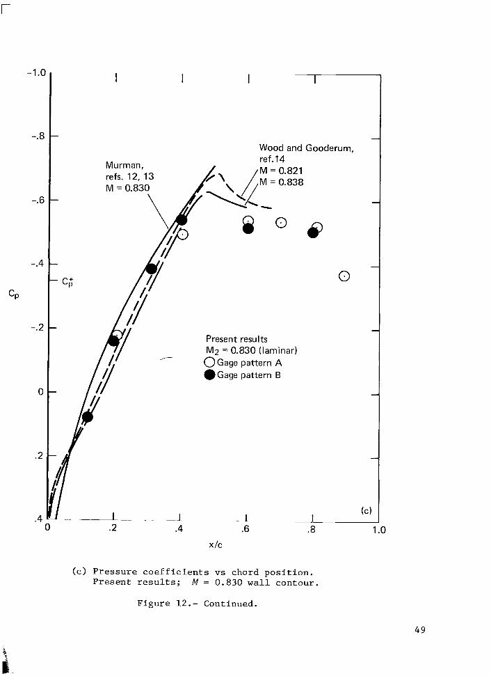
r
-1 .o
-.8
-.6
-.4
CP
-. 2
0
.2
.4
I I I
0 .2 .4
I
Wood and Gooderum, ref. 14 M = 0.821 M = 0.838
Present results M2 = 0.830 (laminar)
O G a g e pattern A .Gage pattern B
- 1 .6
x/c
Q
0
(C: I
( c ) P r e s s u r e c o e f f i c i e n t s vs chord p o s i t i o n . P resen t r e s u l t s ; M = 0.830 w a l l contour .
.8 1 .o
Figure 12 . - Continued.
4 9
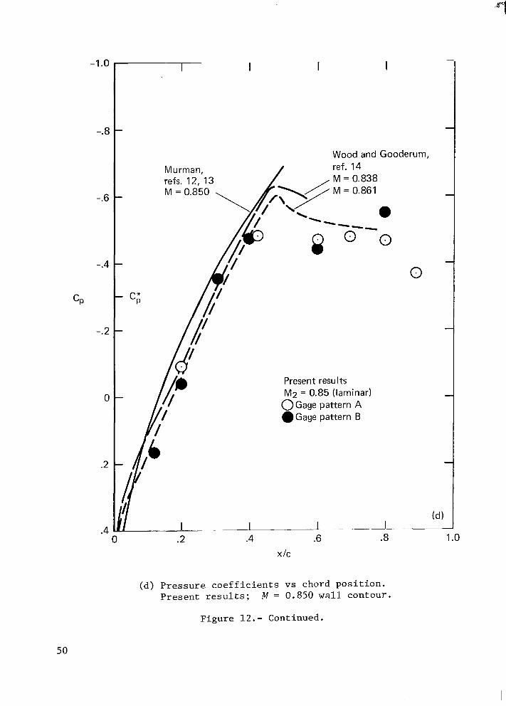
-1 .o
-.8
-.6
-.4
CP
-.2
0
.2
.4
I I I I
Wood and Gooderum, Murman, ref. 14 refs. 12, 13 h-9 M M = = 0.838 0.861
--- -
M = 0.850 \
0 t -
.I '.-
. . 0 .2
I
g o o 0
Present resu I t s M2 = 0.85 (laminar)
O G a g e pattern A @Gage pattern B
(d) I ~ .~I
x I C
(d) P r e s s u r e c o e f f i c i e n t s vs chord p o s i t i o n . P r e s e n t r e s u l t s ; M = 0.850 wall contour .
F i g u r e 12.- Continued.
50
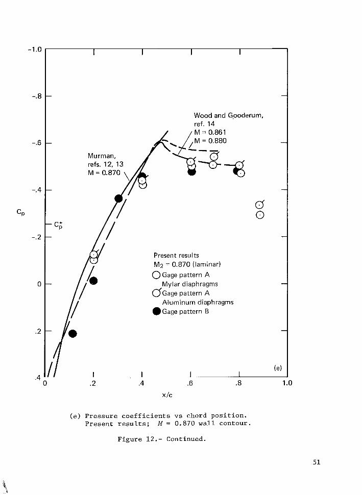
-1 .o
-.8
-.6
-.4
CP
-.2
0
.2
.4 0
I I I I
Wood and Gpoderum, ref. 14
Present results M2 = 0.870 (laminar) 0 Gage pattern A
G G a g e pattern A
.Gage pattern B
Mylar diaphragms
Aluminum diaphragms
0 0
(e I 1 1
.2 .4 .6 .8 1 .o x I C
(e) Pressure coefficients vs chord position. Present results; M = 0.870 wall contour.
Figure 12.- Continued.
51
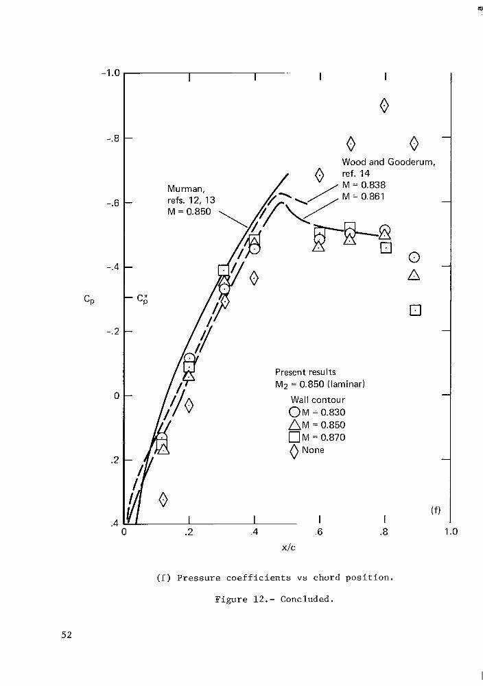
-1 .o
-.8
-.6
-.4
CP
-. 2
0
.2
.4
I I I I
0
0 0 Wood and Gooderum.
Murman,
0 .2 .4
Present results M2 = 0.850 (laminar)
Wall contour O M = 0.830 A M = 0.850 O M = 0.870 0 None
I .6
X I C
0 A
0
( f l 1
.8 1 .o
( f ) P r e s s u r e c o e f f i c i e n t s vs chord p o s i t i o n .
F i g u r e 12 . - Concluded.
52
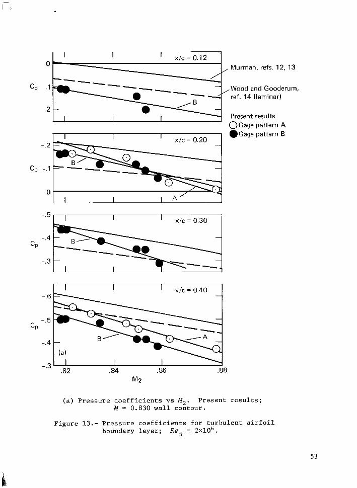
I x / r ! = 0.12 I ' I I
CP
. . , - -. . -
. I
I
.2 - I
. Murman, refs. 12,
,Wood and Goodei ref. 14 (laminar)
Present results O G a g e pattern A @Gage pattern B ' x / c = 0.20 1 I
-
I x l c = 0.30 I
CP
-.6
-.5
-.4
-.3 .82 .84 .86 .88
M2
(a) P r e s s u r e c o e f f i c i e n t s vs M,. P r e s e n t r e s u l t s ; M = 0.830 w a l l con tour .
13
rum,
F i g u r e 13.- P r e s s u r e c o e f f i c i e n t s f o r t u r b u l e n t a i r f o i l boundary l a y e r ; Rec = 2 ~ 1 0 ~ .
53
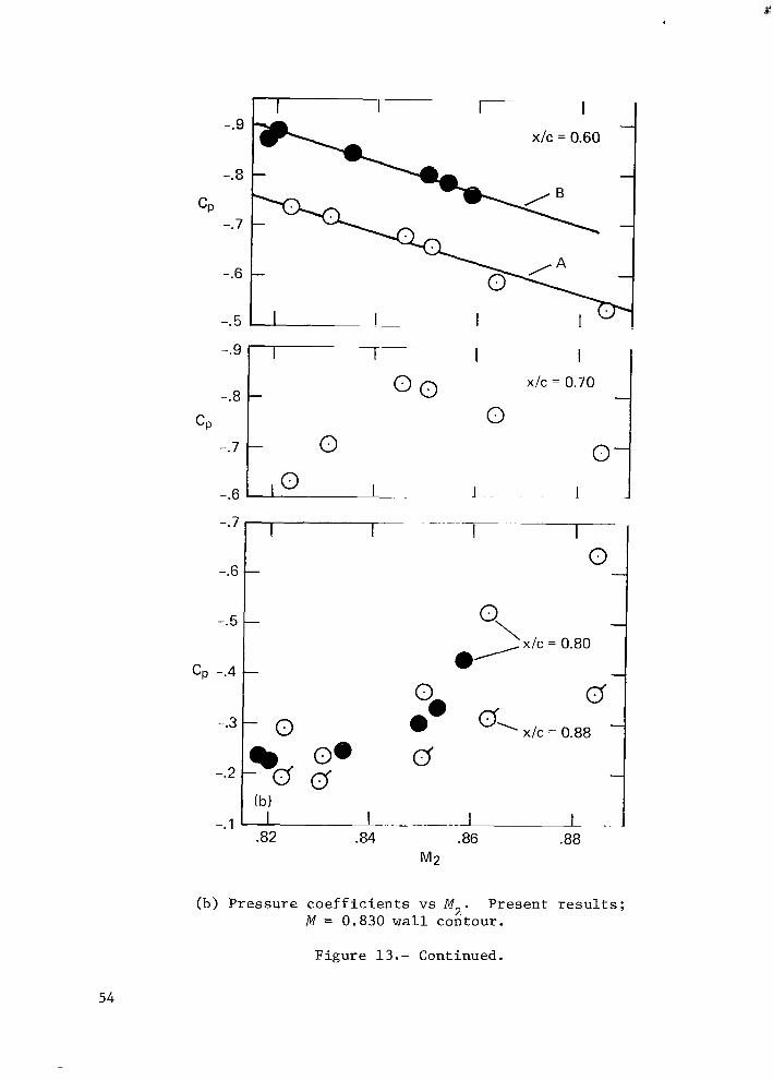
-.9
-.8
CP -. 7
-.6
-.5
2 I I - x lc = 0.60
-
1 - I I
0
1
xfc = 0.70
0 ~. I
-.7 I”- I
c, -.4
-.l 1 ‘ -82 .84 .86 .88
M2
(b) P r e s s u r e c o e f f i c i e n t s vs M,. P r e s e n t r e s u l t s ; M = 0.830 w a l l con tour .
F i g u r e 13.- Continued.
54
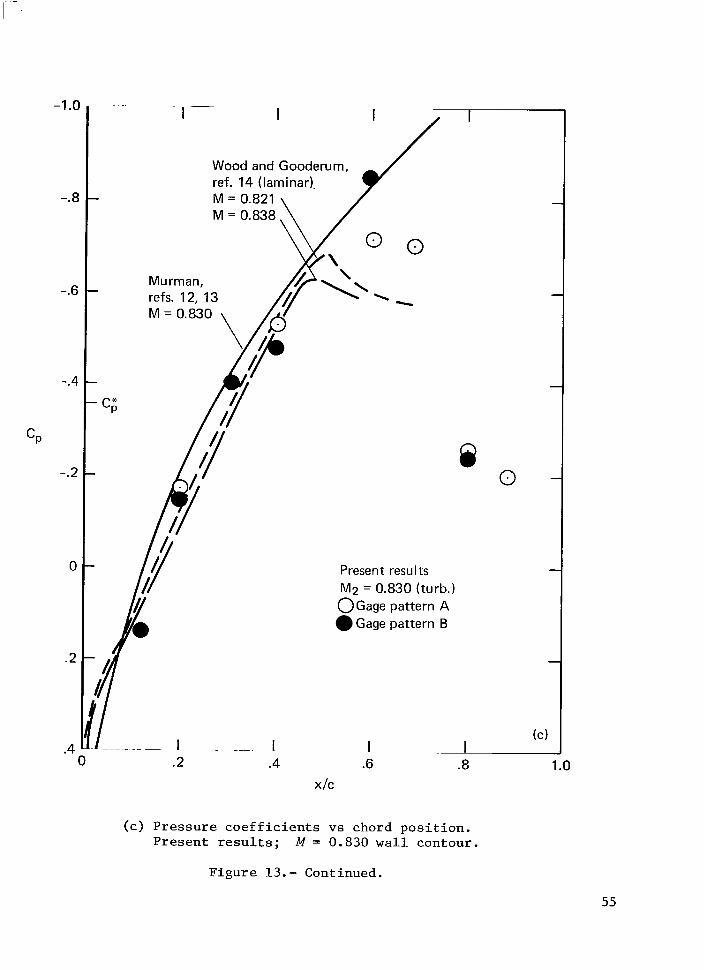
-1.0
-.8
-.6
-.4
CP
-.2
0
.2
. . 0
Present resu I ts M2 = 0.830 (turb.) O G a g e pat tern A
Gage pat tern B
1 ~ 1 .2 .4
I
0 Q
(c1 1 1 1
.6 .8 1 .o x I C
(c) Pressure coefficients vs chord position. Present results; M = 0.830 w a l l contour.
Figure 13. - Continued.
55
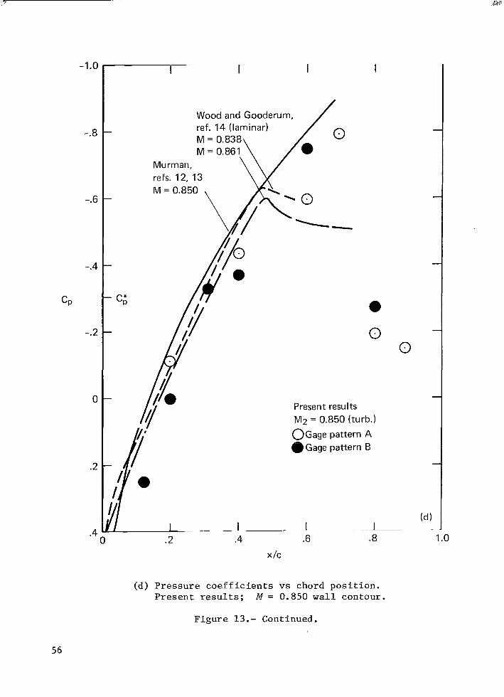
-1.0
-.8
-.6
-.4
CP
-.2
0
.2
.4 0
I I I
Wood ref. 14 and (laminar) G o o d e k
M = 0.838 M = 0.861 \ Murman, \
refs. 12, 13 \ K \ M = 0.850
I
I
a 0 0
Present resu Its M2 = 0.850 (turb.)
O G a g e pattern A a Gage pattern B
.2 .4 .6 x / c
-.I .8 1 .o
(d) Pressure coefficients vs chord position. Present results; M = 0.850 w a l l contour.
Figure 13.- Continued.
56
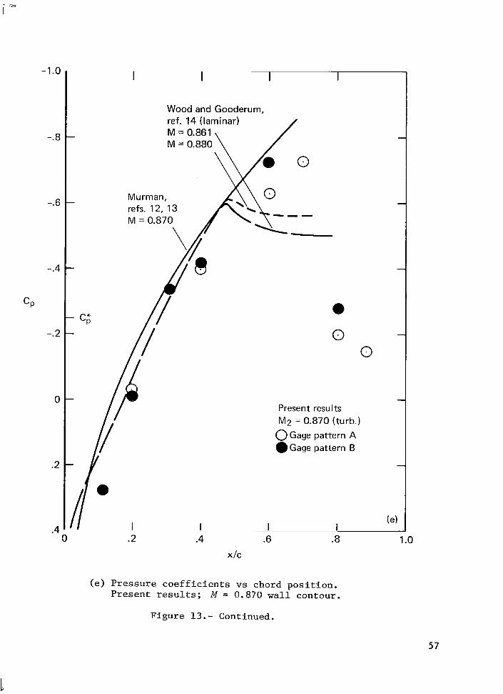
-1 .o
-.8
-.6
-.4
CP
-.2
0
.2
.4 . .
0
I I I I
6 0 0
Wood and Gooderum, ref. 14 (laminar)
M = 0.870
0 0
Present results M2 = 0.870 (turb.) 0 Gage pattern A .Gage pattern B
(e' I I I I
X I C
(e) P r e s s u r e c o e f f i c i e n t s vs chord p o s i t i o n . P r e s e n t r e s u l t s ; M = 0.870 w a l l contour .
F i g u r e 13.- Continued.
57
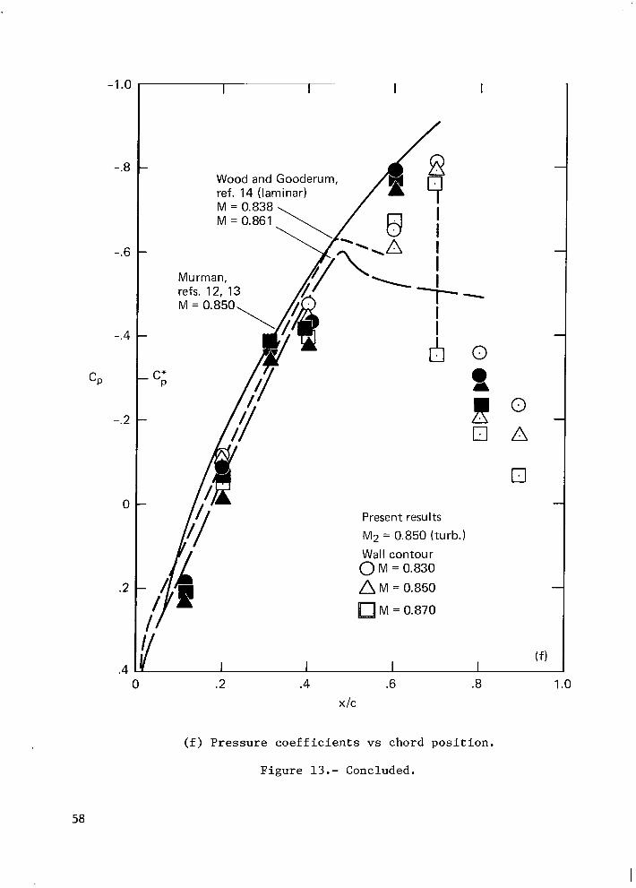
-.8 - Wood and Gooderum, ref. 14 (laminar)
-.6 -
-.4 -
CP
-.2 -
0
Present results M2 = 0.850 (turb.)
A M = 0.850
M = 0.870
( f )
0 .2 .4 .6 .8 1 .o x I C
( f ) P r e s s u r e c o e f f i c i e n t s vs chord p o s i t i o n .
F igu re 13.- Concluded.
58
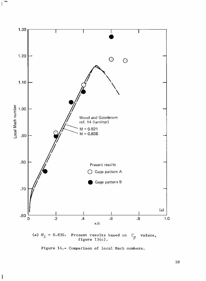
1.30
1.20
1.10
k 1.00
2 5 .90
E 3 != L 0
- m u
.80
.70
I I I I a
0 0
\ \
Wood and Gooderum ref. 14 (laminar)
M = 0.821 M = 0.838
Present results
0 Gage pattern A
Gage pattern B
.60
(a ) M, = 0.830. P r e s e n t r e s u l t s based on C v a l u e s , f i g u r e 1 3 ( c ) . P
F i g u r e 14.- Comparison of l o c a l Mach numbers.
59
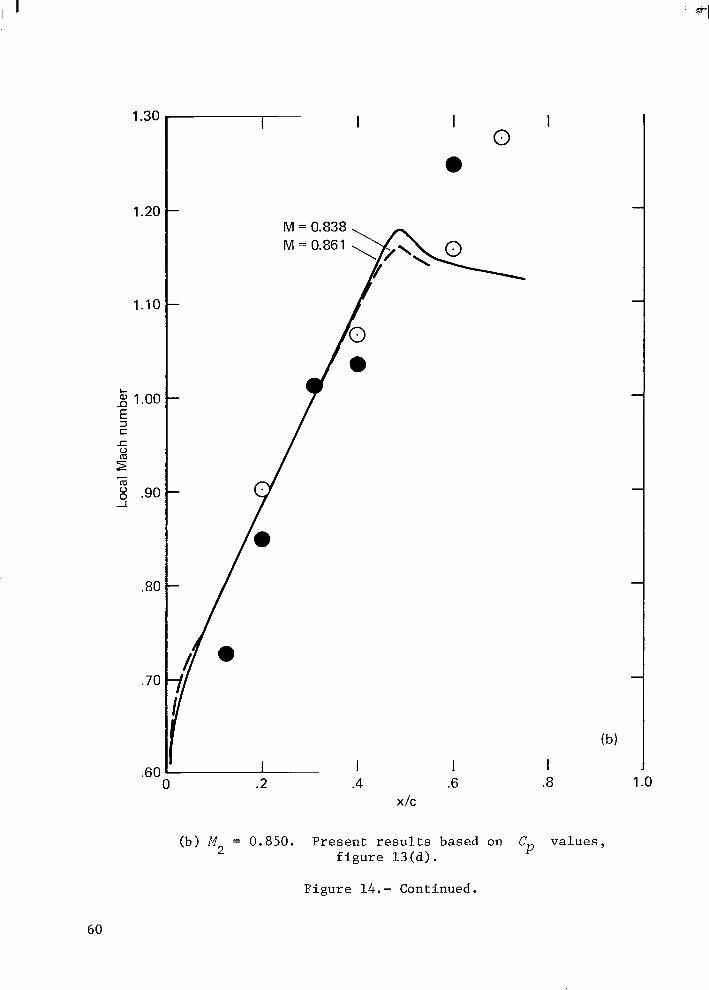
1.30
1.20
1.10
L 2 1.00 E 3 C J= 0
r" - m -I 8 .90
.80
.70
.60
I I
M = 0.838 M = 0.861
1 0 .2
I I 0
a
m
(b)
I .- I I
X I C
(b) M 2 = 0.850. P r e s e n t r e s u l t s based on Cp v a l u e s , f i g u r e 13 (d ) .
F i g u r e 14.- Continued.
60
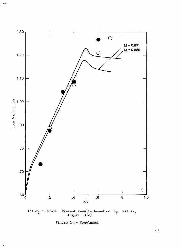
1.30
1.20
1.10
L
2 1.00 E 3 S 1 0
r" g .90 - m -I
.80
.70
.60 0
I I
I I 1 I .2 .4 .6 .8 1 .o
x I C
( c ) M, = 0.870. P r e s e n t r e s u l t s based on Cp v a l u e s , f i g u r e 13 (e).
F i g u r e 14.- Concluded.
61
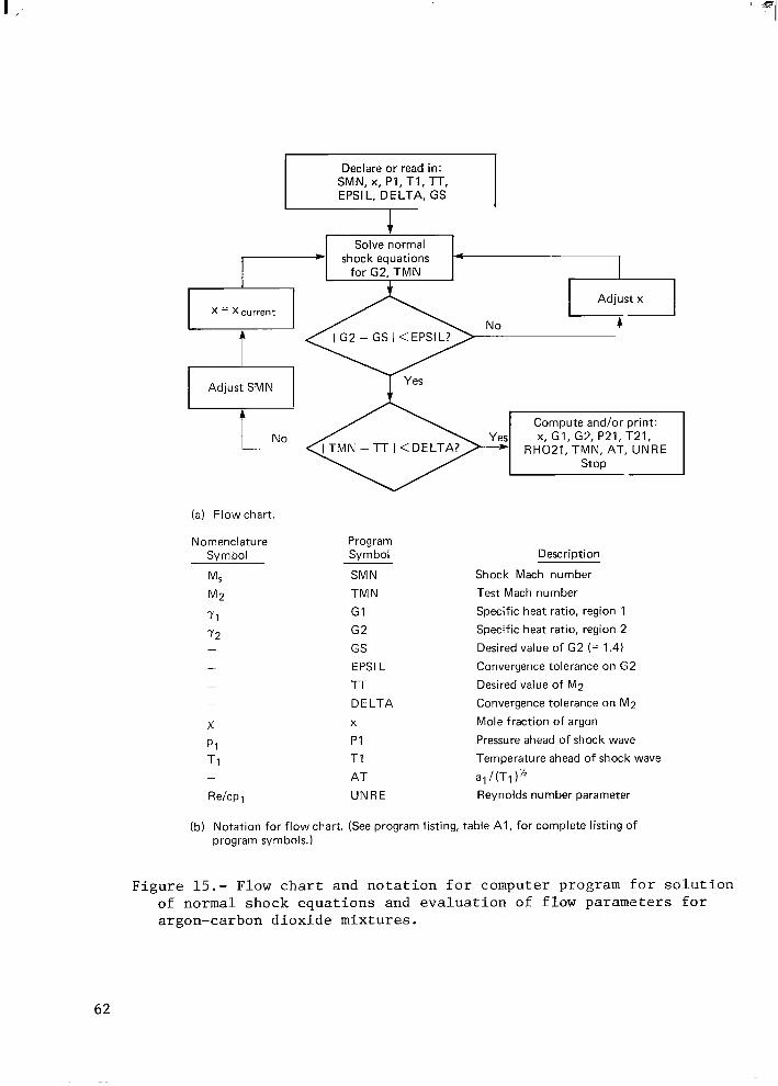
Declare or read in: SMN, x, PI, T1, TT, EPSIL, DELTA, GS
r l Adjust SMN
t- Solve normal -1 shock equations for G2, TMN
-FA I I NO -1 Compute X . G I . G ~ ~ ~ ~ . T ~ ~ . and/or print: 1 I TMN - TT I <DELTA? RH021, TMN, AT, UNRE
(a) Flow chart.
Nomenclature Symbol
M*
M2
71
7 2 -
Program Symbol
SMN TMN
G I G2 GS EPSl L
TT
DELTA X
P I T I
AT UNRE
Description
Shock Mach number Test Mach number Specific heat ratio, region 1 Specific heat ratio, region 2 Desired value of G2 (= 1.4)
Convergence tolerance on G2
Desired value of M2 Convergence tolerance on M2
Mole fraction of argon Pressure ahead of shock wave
Temperature ahead of shock wave
a1 /(TI )"
Reynolds number parameter
(b) Notation for flow chart. (See program listing, table A I , for complete listing of program symbols.)
F i g u r e 15.- Flow c h a r t and n o t a t i o n f o r computer program f o r s o l u t i o n of normal shock e q u a t i o n s and e v a l u a t i o n of f low parameters f o r argon-carbon d i o x i d e mixtures .
62
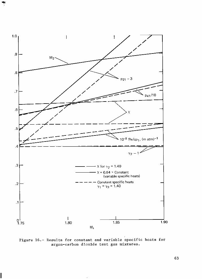
1 .o
.9
.8
.7
.E
5 ..
-- X for 72 = 1.40
X = 0.64 = Constant (variable specific heats)
----- Constant specific heats 71 = 7 2 = I .40
-
75 1.80 1.85 Ms
1.90
F i g u r e 16.- R e s u l t s f o r c o n s t a n t and v a r i a b l e s p e c i f i c h e a t s f o r argon-carbon d i o x i d e test gas mix tu res .
63
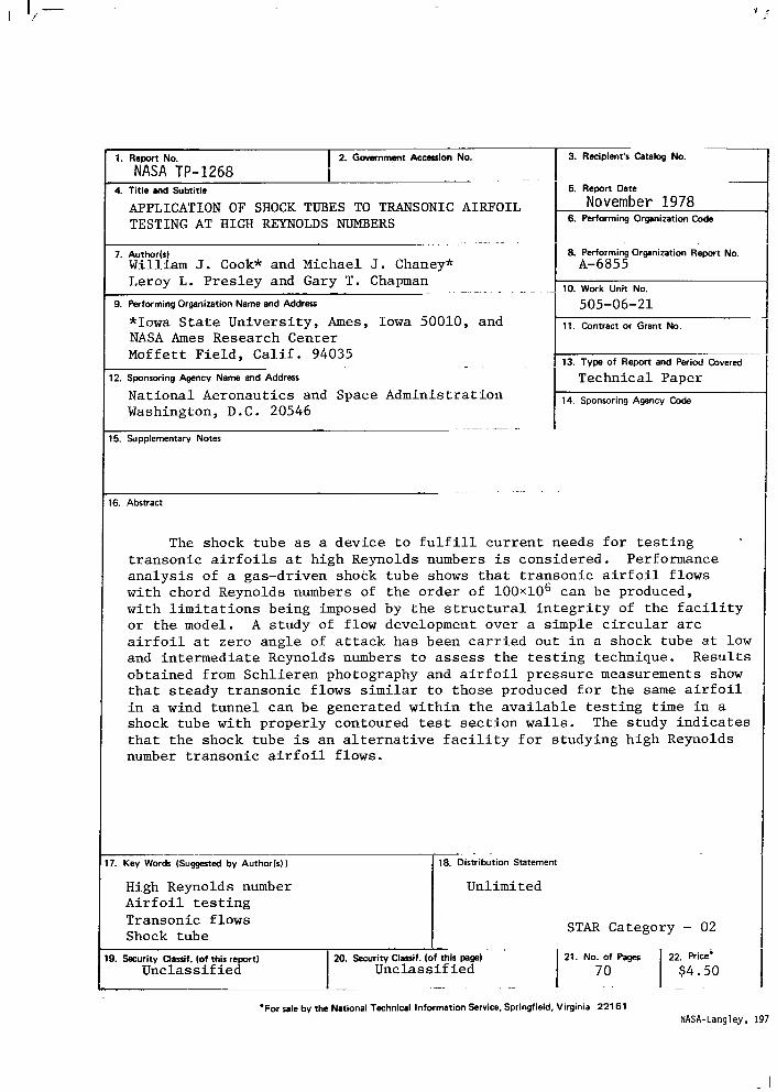
I '7
1. R e m No. NASA TP-1268
2. Government Accession No.
- . . . .
3. Recipient's Catalog No.
19. Security Classif. (of this report) Unclass i f ied
~
5. Report Date
6. Performing Organization Code November 1978
. . 20. Security Classif. (of this pagel 21. No. of Pegs 22. Rice.
Unclass i f ied I 70 $4.50 . - - -. . .
8. Performing Organization Report No. A-6855
10. Work Unit No.
505-06-21 11. Contract or Grant No.
13. Type of Report and Period Covered
Technical Paper 14. Sponsoring Agency Code
The shock tube as a device t o f u l f i l l c u r r e n t needs f o r t e s t i n g t ransonic a i r f o i l s a t high Reynolds numbers i s considered. Performance a n a l y s i s of a gas-driven shock tube shows t h a t t ransonic a i r f o i l flows with chord Reynolds numbers of t h e order of 1 0 0 ~ 1 0 ~ can be produced, with l i m i t a t i o n s being imposed by t h e s t r u c t u r a l i n t e g r i t y of t h e f a c i l i t y o r t h e model. A s tudy of flow development over a simple c i r c u l a r a r c a i r f o i l a t zero angle of a t t a c k has been carried out i n a shock tube a t low and intermediate Reynolds numbers t o assess t h e t e s t i n g technique. Resul t s obtained from Schl ie ren photography and a i r f o i l p ressure measurements show t h a t s teady t ransonic flows s imilar t o those produced f o r t h e s a m e a i r f o i l i n a wind tunnel can be generated wi th in t h e a v a i l a b l e t e s t i n g time i n a shock tube with properly contoured test s e c t i o n w a l l s . t h a t t h e shock tube i s an a l t e r n a t i v e f a c i l i t y f o r s tudying high Reynolds number t ransonic a i r f o i l flows.
The s tudy i n d i c a t e s
. . . . - __ ( w ( W o r d r ( S u g g s t e d by Author(s1) 18. Distribution Statement
High Reynolds number A i r f o i l t e s t i n g Transonic flows Shock tub e
Unlimited I STAR Category - 02
‘: 1 Postage and Fees Paid National Aeronautics and Space Administration N A S A 4 5 1 [%-
USMAIL
National Aeronautics and Space Administration
Washington, D .C. 20546 Official Business
Penalty for Private Use, $300
THIRD-CLASS B U L K R A T E
1 1 I U , A , 7 0 2 7 7 8 S00903DS DEPT OF THB AIR FUBCE AP WEAPONS L A E O R A T Q R Y ATTN: T E C H N I C l L L I B B A R Y (SUI,) KIRTLAND A P B BM 87113
‘i
I.. .-
If Undeliverable (Section 15 Postal Manual) Do Not Retu