Embed Size (px)
Citation preview
This file passed thru Volkswagen Technical Site - http://volkswagen.msk.ru/
2002 Volkswagen GTI 2002-03 AUTOMATIC TRANSMISSIONS
Servicing - 09A
APPLICATION
TRANSAXLE APPLICATION
IDENTIFICATION
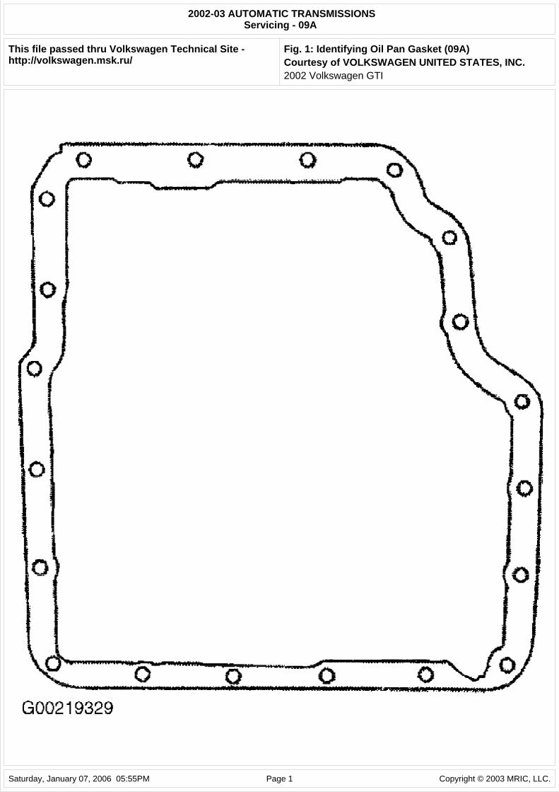
OIL PAN GASKET
Fig. 1: Identifying Oil Pan Gasket (09A) Courtesy of VOLKSWAGEN UNITED STATES, INC.
LUBRICATION
SERVICE INTERVALS
Transaxle & Final Drive
Transaxle and final drive are checked and filled together. Check fluid level at 20,000 mile intervals. Fluid is filled for life. No changing is required.
CHECKING FLUID LEVELS
09A Transaxle
1.
Transaxle ATF temperature must not be above about 86 deg. F (30 deg. C). Vehicle must be on level surface and selector lever must be in "P" position. Connect VAG 1924 ATF filling system to vehicle.
2.
Connect VAG Scan Tool (1551) and enter address word "02 Transmission electronics" and advance until "Select function XX" is indicated on display.
3. Press keys 0 and 8. (The function "Read measured value block" is selected with 08). Confirm entry with key "Q". Press keys 0 0 2 (002 selects the "Display group number 002"). Confirm entry with key "Q". The third display zone shows the ATF temperature.
Application Transaxle Model GTI (1.8L) 09A 5-Speed Jetta (1.8L & 2.8L) 09A 5-Speed
NOTE: In the following procedures, numbers in parenthesis are shown in illustrations.
NOTE: When ATF level is checked, the seal on the inspection plug must always be replaced. VAG Scan Tool (1551) and Diagnosis Cable (1551/1) are required to check ATF level. Scan tool is used to measure ATF temperature. Follow aftermarket scan tool manufacturer instructions (if applicable) to check ATF temperature.
NOTE: The following detailed test procedures are described for VAG Scan Tool (1551).
2002 Volkswagen GTI
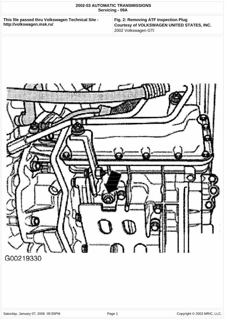
4. The ATF temperature must not be more than about 86 deg. F (30 deg. C) at the start of test. Start engine. Raise and support vehicle. Place drain pan under the transaxle. Bring ATF to test temperature of 95-113 deg. F (35-45 deg. C). Remove ATF inspection plug (arrow) from transaxle housing. See Fig. 2.
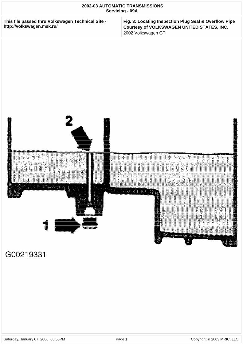
5. The ATF present in the overflow pipe (2) will run out. If ATF drips out of hole, ATF does not need to be topped off. Install NEW seal (1) to ATF inspection plug and tighten to 11 ft. lbs. (15 N.m). ATF check is completed. See Fig. 3. If only the ATF present in the overflow pipe runs out of hole, top off ATF.
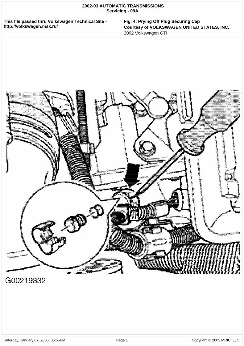
6. To top off ATF, pry off plug securing cap (arrow) with a screwdriver. See Fig. 4. The securing cap locking device will be destroyed when doing this, so always replace securing cap. Pull plug out of filler pipe.
7.
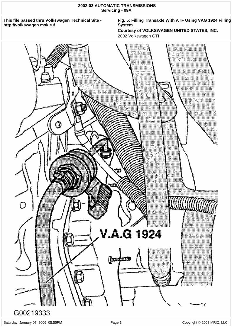
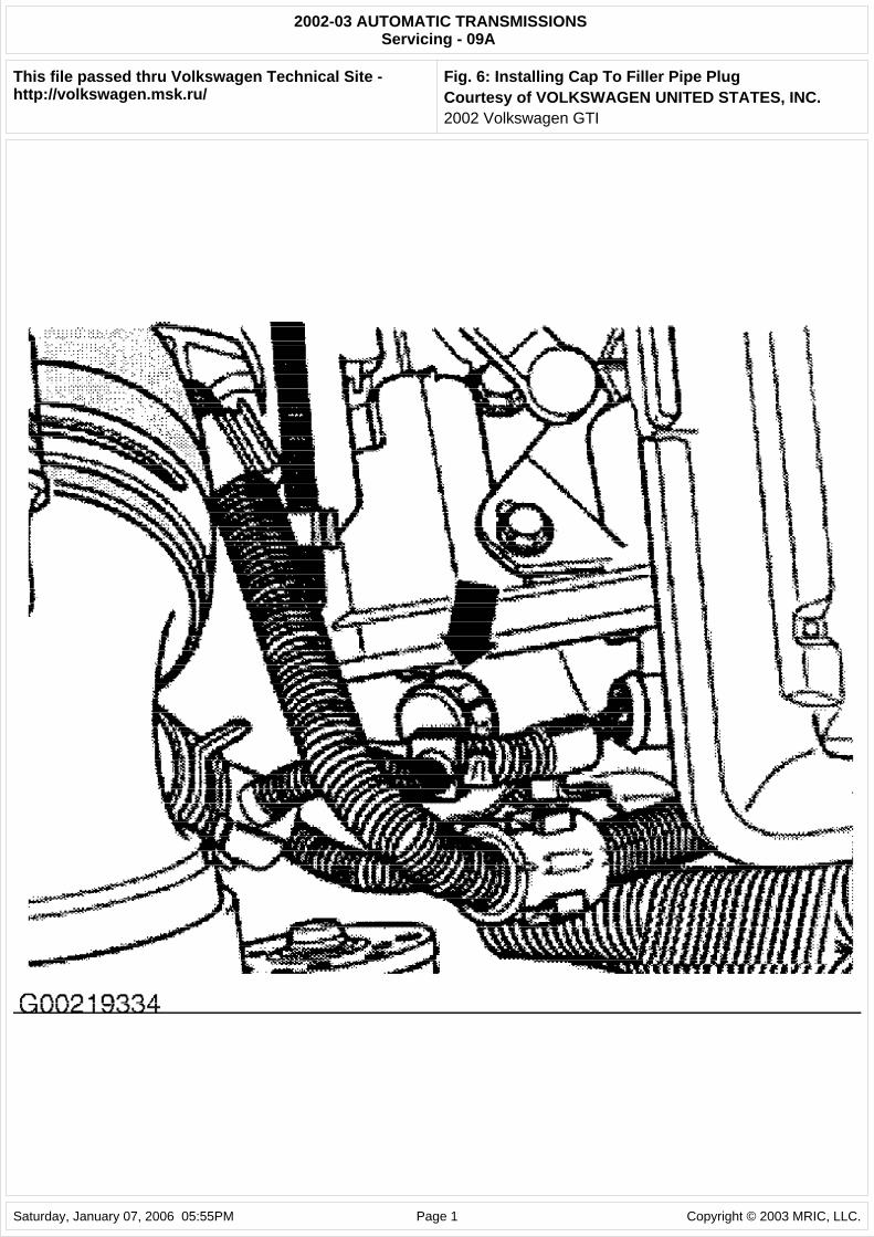
Fill transaxle with ATF using VAG 1924 ATF filling system until ATF runs out of inspection hole. See Fig. 5. Install NEW seal (1) to inspection plug and tighten to 11 ft. lbs. (15 N.m). See Fig. 3. Install plug on filler pipe and secure with a NEW cap (arrow). See Fig. 6. Lock cap in place. The cap secures the sealing plug.
8. To end VAG Scan Tool (1551) output, press right arrow key. Press keys 0 and 6 (the function "End output" is selected with 06). Confirm entry with "Q" key. Lower vehicle and turn ignition off. Remove scan tool.
09A Final Drive
Transaxle and final drive are checked and filled together.
Fig. 2: Removing ATF Inspection Plug Courtesy of VOLKSWAGEN UNITED STATES, INC.
Fig. 3: Locating Inspection Plug Seal & Overflow Pipe Courtesy of VOLKSWAGEN UNITED STATES, INC.
Fig. 4: Prying Off Plug Securing Cap Courtesy of VOLKSWAGEN UNITED STATES, INC.
Fig. 5: Filling Transaxle With ATF Using VAG 1924 Filling System Courtesy of VOLKSWAGEN UNITED STATES, INC.
Fig. 6: Installing Cap To Filler Pipe Plug Courtesy of VOLKSWAGEN UNITED STATES, INC.
RECOMMENDED FLUIDS
RECOMMENDED FLUIDS
FLUID CAPACITIES
TRANSAXLE FLUID CAPACITIES
NOTE: An insufficient amount of ATF, as well as filling ATF to excess, affects the function of the transaxle.
Application Fluid Type Transaxle & Final Drive (1)VW ATF (G 052 990 A2) (1) Fluid is Light Yellow in color.
Application Refill - Qts. (L) Dry-Fill - Qts. (L) 09A 2.6 (2.5) 7.4 (7.0)
2002 Volkswagen GTI
FINAL DRIVE FLUID CAPACITY
DRAINING & REFILLING
09A Transaxle
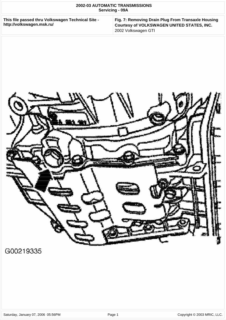
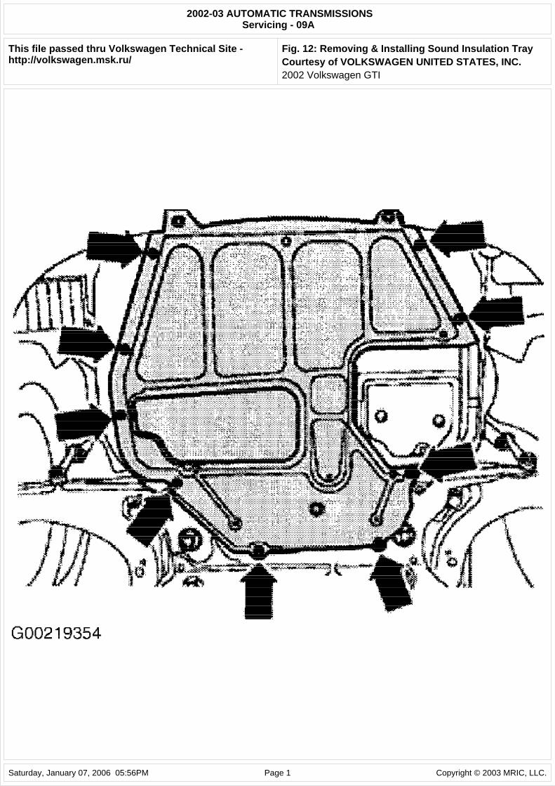
1. To replace ATF, raise and support vehicle. Remove sound insulation tray (arrows). See Fig. 12. Place drain pan under the transaxle. Remove drain plug from transaxle housing. See Fig. 7. Drain ATF. Install drain plug with new seal and tighten to 33 ft. lbs. (45 N.m).
2. Fill with appropriate amount of ATF through filler pipe using VAG 1924 ATF filling system. See FLUID CAPACITIES . See Fig. 5. Start engine and shift transaxle through all the selector lever positions with the vehicle stationary. Check and top off ATF level. See CHECKING FLUID LEVELS .
Fig. 7: Removing Drain Plug From Transaxle Housing Courtesy of VOLKSWAGEN UNITED STATES, INC.
ON-VEHICLE REPAIRS
ADJUSTMENTS
LOCKING CABLE
1. Ensure locking cable is correctly fitted. Remove center console. Shift selector lever to "P" position. Turn ignition key to LOCK position. Place steering wheel in rear/lower position.
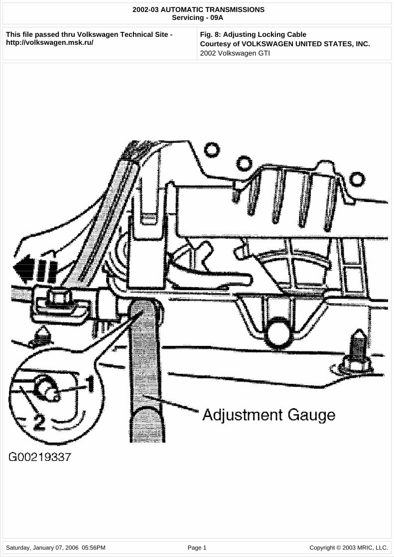
2. Unscrew bolt from support bracket. Position locking cable Adjustment Gauge (3352A) between locking lever (1) and locking cable eye (2). See Fig. 8.
3. To take up play, pull support bracket onto stop in direction of arrow. See Fig. 8. Locking cable adjustment gauge must be easy to remove and insert in this position. Tighten bolt on support bracket to 89 INCH lbs. (10 N.m). Remove adjustment gauge. Ensure ignition key operates properly.
Fig. 8: Adjusting Locking Cable Courtesy of VOLKSWAGEN UNITED STATES, INC.
SELECTOR LEVER CABLE
Checking & Adjusting
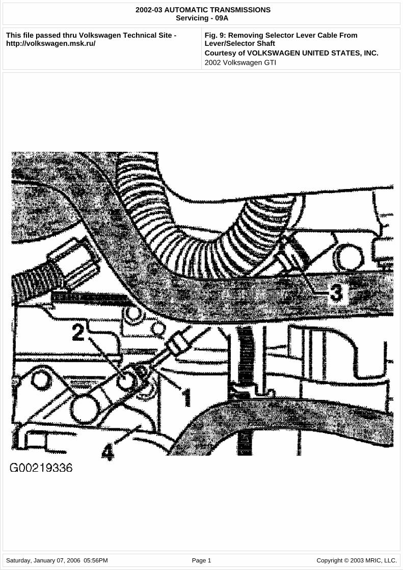
1. To check cable, shift selector lever to "P" position. Pull selector lever cable (1) upward off lever/selector shaft (4) and position so that end is free to move. See Fig. 9. Do not kink or bend selector lever cable. Shift selector lever from "P" to "2" position. Check front protective sleeve on selector lever cable for damage, and replace cable if necessary.
2. Shift selector lever to "P" position. Selector lever mechanism and selector lever cable must move freely. If necessary, replace selector lever cable or service selector lever mechanism. Press selector
Application Qts. (L) 09A (1)
(1) Transaxle and final drive are checked and filled together.
NOTE: Various components may be serviced without transaxle removal. For servicing of these components, see appropriate component under ADJUSTMENTS and/or REMOVAL & INSTALLATION .
NOTE: In the following procedure, numbers in parenthesis are shown in illustration.
NOTE: In the following procedures, numbers in parenthesis are shown in illustration.
2002 Volkswagen GTI
lever cable onto lever/selector shaft using a pair of pliers. Replace circlip (3) if it has been removed. See Fig. 9.
3. To adjust cable, place selector lever in "P" position. Loosen adjustment bolt (2) at front ball socket of selector lever cable (1). See Fig. 9. Place selector shaft lever in "P" position on transaxle. Locking lever must engage in park lock wheel, with both front wheels locked (cannot be turned together in any direction). Tighten adjustment bolt on selector lever cable to 115 INCH lbs. (13 N.m). Ensure selector lever operates properly.
Fig. 9: Removing Selector Lever Cable From Lever/Selector Shaft Courtesy of VOLKSWAGEN UNITED STATES, INC.
REMOVAL & INSTALLATION
DRIVE AXLE FLANGE SHAFT OIL SEALS
Removal & Installation (Left Flanged Shaft)
1. Raise and support vehicle. Remove left wheel. Remove sound insulation tray (arrows). See Fig. 12. Remove left hand sound insulation. Turn steering to left lock position. Disconnect drive axle from flanged shaft. Mark installation position of lower ball joint bolts on left hand control arm and remove bolts.
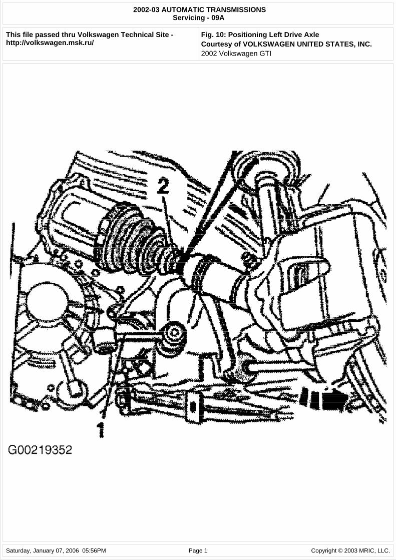
2. Disconnect left connecting link (1) from control arm and turn link upward. Swing wheel bearing housing outward. Guide left drive axle (2) out between subframe and transaxle. See Fig. 10. Lift drive axle and secure to suspension strut with wire.
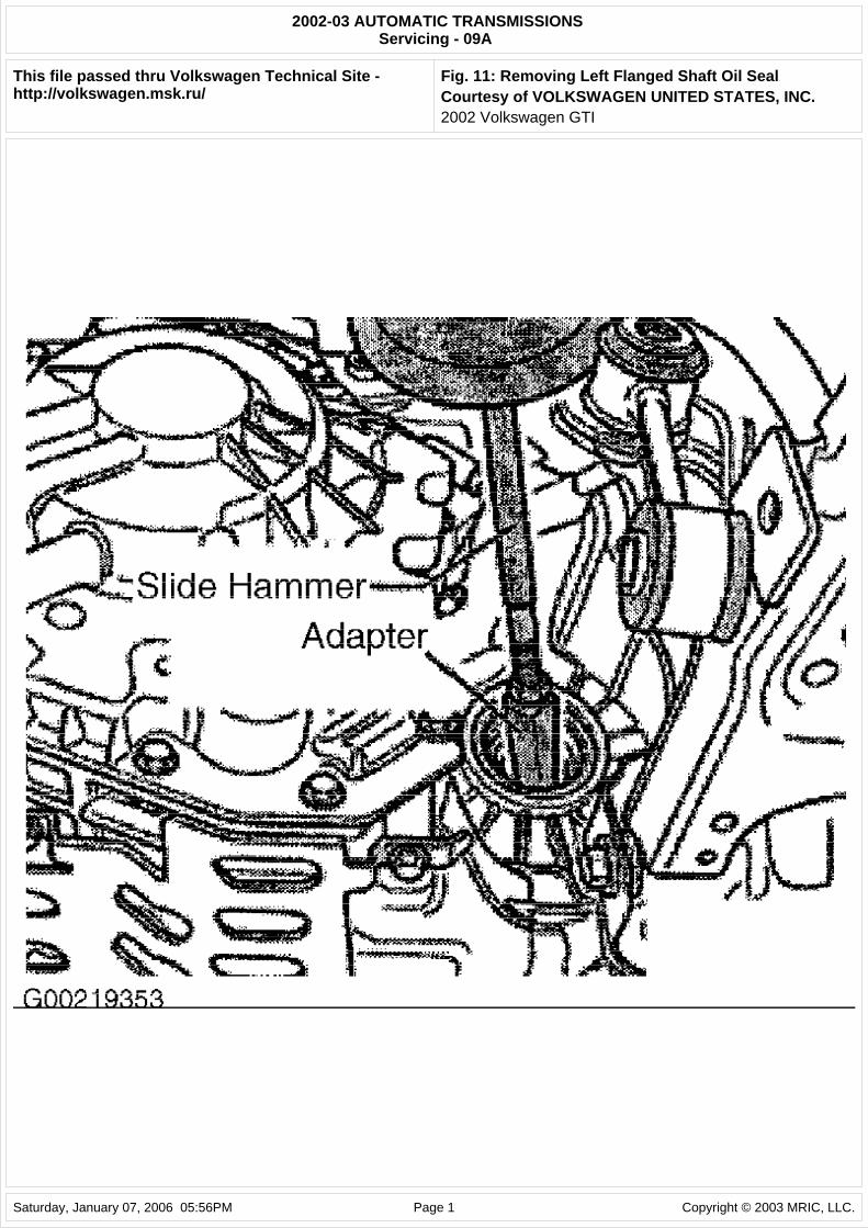
3. Remove flange shaft securing bolts by threading 2 bolts into flange and counterholding flange shaft using a lever. Place drain pan under transaxle. Remove flanged shaft with spring from transaxle. Pull flange shaft oil seal out using appropriate slide hammer and adapter. See Fig. 11.
4. To install oil seal, drive in NEW seal until thrust driver contacts stop. Ensure that seal remains straight during installation. Insert flange shaft. Apply sealant to head of countersunk bolt. Secure flange shaft with countersunk bolt. Connect ball joint to control arm using NEW bolts onto old impression marks. Tighten bolts to 15 ft. lbs. (20 N.m). Bolt left hand drive axle to flange shaft. Tighten bolts to 18 ft. lbs. (25 N.m).
5. Install left wheel. Tighten bolts to 89 ft. lbs. (120 N.m). Check and top off ATF level. See CHECKING FLUID LEVELS under LUBRICATION. Install sound insulation tray.
Fig. 10: Positioning Left Drive Axle Courtesy of VOLKSWAGEN UNITED STATES, INC.
Fig. 11: Removing Left Flanged Shaft Oil Seal Courtesy of VOLKSWAGEN UNITED STATES, INC.
WARNING: Vehicle is equipped with Supplemental Inflatable Restraint (SIR) system. When servicing vehicle, use care to avoid accidental air bag deployment. SIR system-related components are located in various locations throughout interior and exterior of vehicle, depending on application. Do not use electrical test equipment on or near these circuits. If necessary, deactivate SIR system before servicing components. See appropriate AIR BAG DEACTIVATION PROCEDURES article in GENERAL INFORMATION.
CAUTION: When battery is disconnected, vehicle computer and memory systems may lose memory data. Driveability problems may exist until computer systems have completed a relearn cycle. See COMPUTER RELEARN PROCEDURES article in GENERAL INFORMATION before disconnecting battery.
NOTE: In the following procedures, numbers in parenthesis are shown in illustration.
2002 Volkswagen GTI
Removal & Installation (Right Flanged Shaft)
1. Remove sound insulation tray (arrows). See Fig. 12. Remove right sound insulation. Turn steering to right onto full lock stop position. Disconnect drive axle from flanged shaft. Raise right drive axle and secure. Remove flange shaft securing bolts by threading 2 bolts into flange and counterhold flange shaft using a lever.
2. Place drain pan under transaxle. Remove flanged shaft with spring. Pull flange shaft oil seal out using appropriate slide hammer and adapter.
3. To install oil seal, drive in NEW seal until thrust driver contacts stop. Ensure seal remains straight during installation. Insert flange shaft. Apply sealant to head of countersunk bolt. Secure flange shaft with countersunk bolt. Bolt right hand drive axle to flange shaft. Tighten bolts to 18 ft. lbs. (25 N.m).
4. Check and top off ATF level. See CHECKING FLUID LEVELS under LUBRICATION. Install sound insulation and tray.
Fig. 12: Removing & Installing Sound Insulation Tray Courtesy of VOLKSWAGEN UNITED STATES, INC.
LOCKING CABLE
Removal & Installation
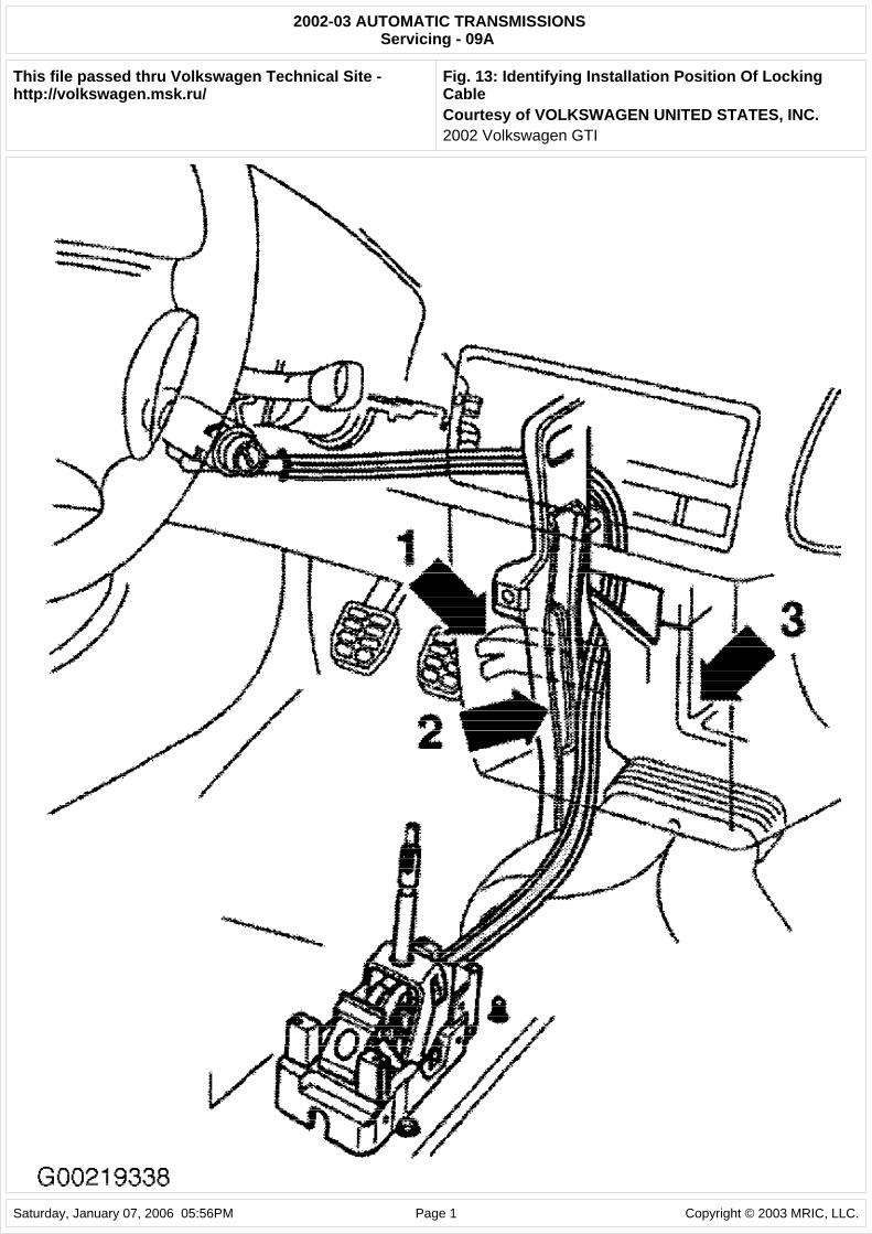
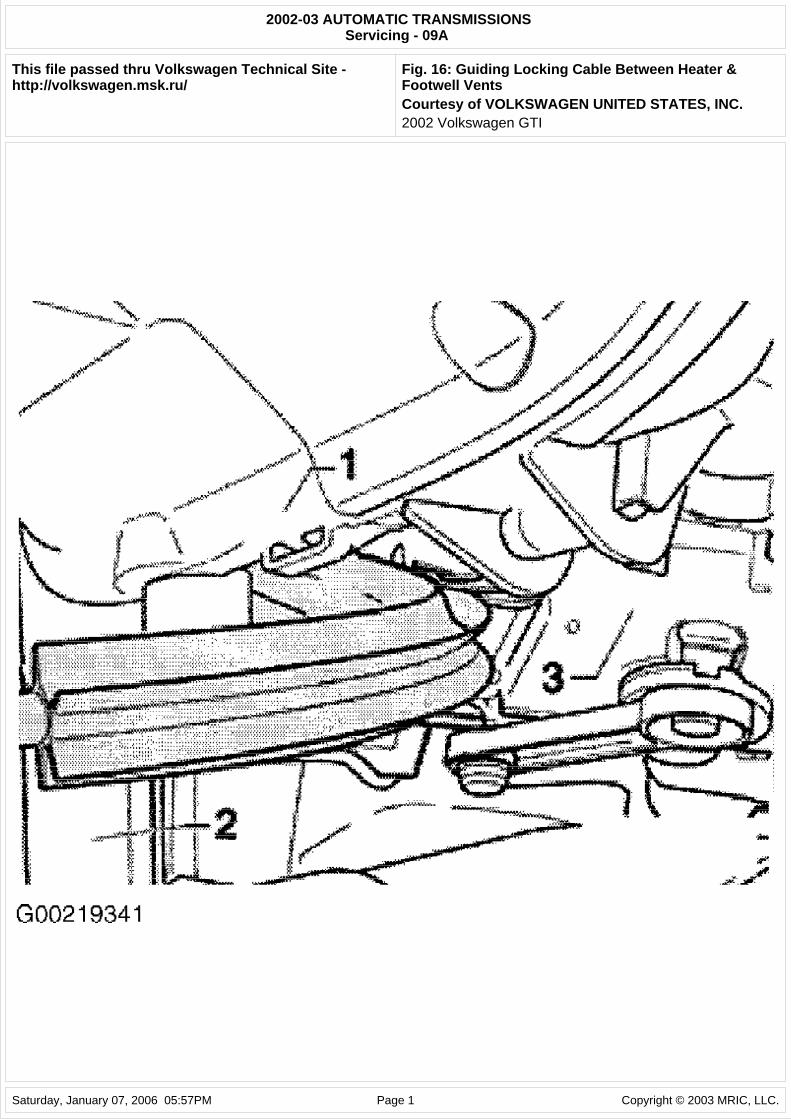
1. Note installation position of locking cable. Cable is routed around footwell vents (1), support/instrument panel (2) and heater unit (3). See Fig. 13. Disconnect negative battery cable. Pull locking cable clip upward off ignition switch.
2. It may be necessary to remove steering wheel and air bag, left trim under instrument panel, steering column trim and steering column adjustment handle to create enough space to remove cable. Turn ignition key to "ignition on" position. Shift selector lever into "P" position.
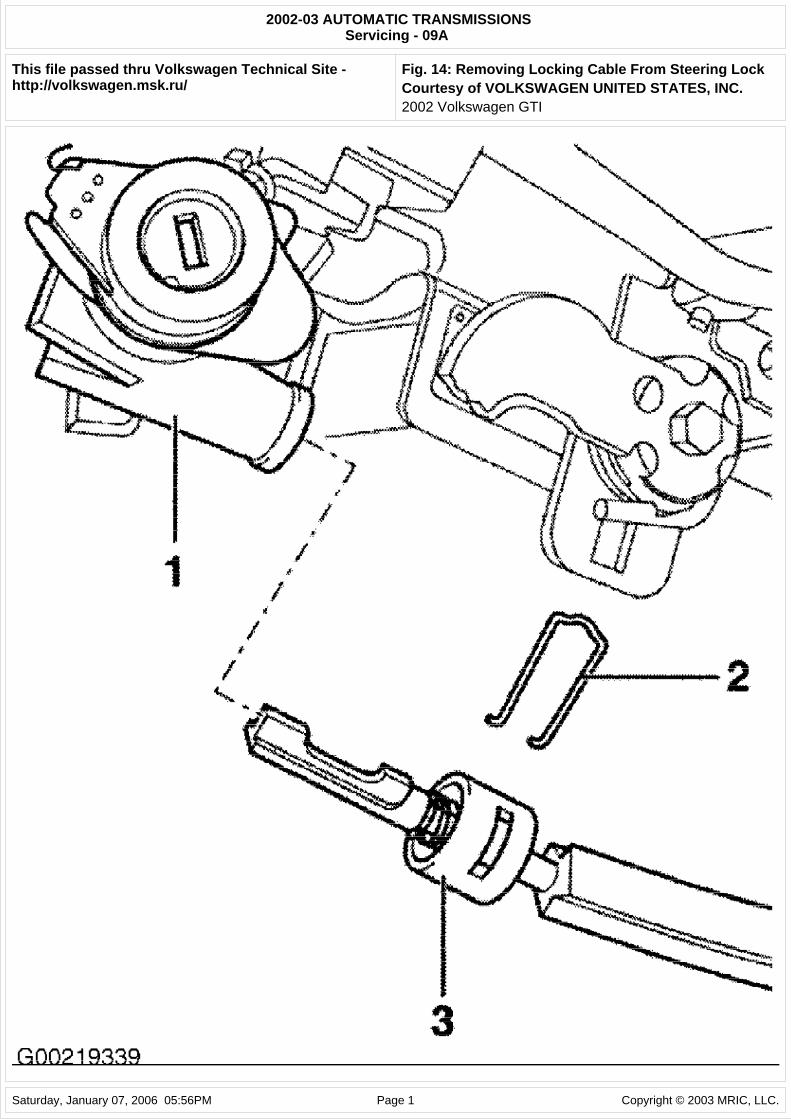
3. Pull out clip (2) for locking cable (3). Pull locking cable out of steering lock (1). See Fig. 14. Press down sleeve on selector lever handle with 2 screwdrivers. Pull selector lever handle off upward. Remove center console.
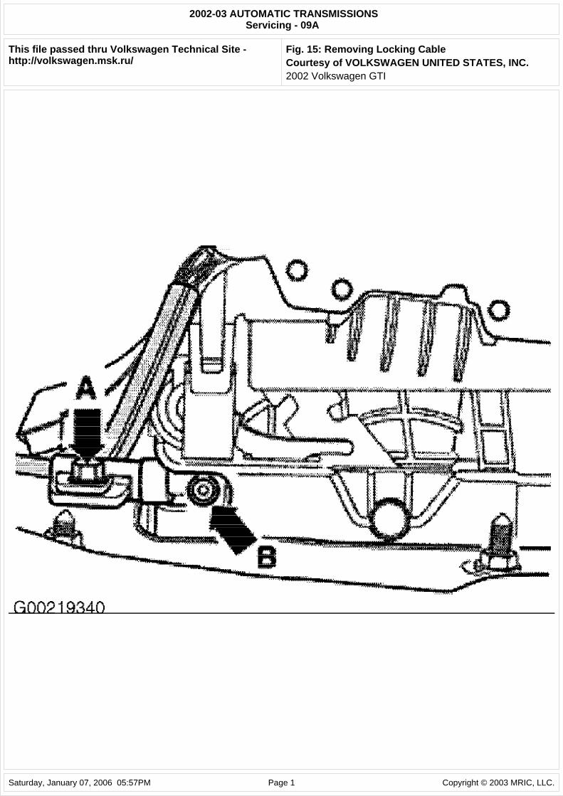
4. Unscrew bolt (arrow A) from locking cable support bracket. Remove locking cable from selector mechanism and locking lever (arrow B). See Fig. 15. Pull locking cable out of instrument panel.
5. To install, reverse removal procedure. Ensure proper routing of locking cable when installing. Locking cable must not be kinked. Guide cable in between heater (3) and footwell vent (1) behind support/instrument panel (2). See Fig. 16. Shift selector lever into "P" position.
6. Pull out cable slightly from cable sheath and engage in locking lever (arrow B). See Fig. 15. Engage
WARNING: Vehicles are equipped with air bag supplemental restraint system. Before attempting ANY repairs involving steering column, instrument panel or related components, see SERVICE PRECAUTIONS and DISABLING & ACTIVATING AIR BAG SYSTEM in appropriate AIR BAG RESTRAINT SYSTEMS article.
NOTE: When battery is disconnected, vehicle computer and memory systems may lose memory data. Driveability problems may exist until computer systems have completed a relearn cycle.
CAUTION: Radio/cassette or radio/CD player is equipped with an anti-theft protection circuit. Whenever battery is disconnected, radio will go into anti-theft mode. When battery is reconnected, radio will display CODE, and will be inoperative until proper code number is entered. Obtain security code before disconnecting battery.
NOTE: In the following procedures, letters and numbers in parenthesis are shown in illustrations.
2002 Volkswagen GTI
cable support bracket in selector lever bracket. Insert locking cable into steering lock (1). See Fig. 14. Flattened side of locking cable faces downward during insertion.
7. Press on clip (2) at locking cable (3). For installation position, push on clip from above. Angled ends of clip face steering lock. See Fig. 14. Ensure that clip is properly located. Adjust locking cable after installation. See LOCKING CABLE under ADJUSTMENTS. Check operation of ignition key withdrawal lock. Install center console. Install selector lever handle. Install left trim under instrument panel.
8. Install steering column trim. Install handle for steering column height and reach adjustment. Install steering wheel and air bag. Reconnect negative battery cable.
Fig. 13: Identifying Installation Position Of Locking Cable Courtesy of VOLKSWAGEN UNITED STATES, INC.
Fig. 14: Removing Locking Cable From Steering Lock Courtesy of VOLKSWAGEN UNITED STATES, INC.
Fig. 15: Removing Locking Cable Courtesy of VOLKSWAGEN UNITED STATES, INC.
Fig. 16: Guiding Locking Cable Between Heater & Footwell Vents Courtesy of VOLKSWAGEN UNITED STATES, INC.
SELECTOR LEVER CABLE
Removal & Installation
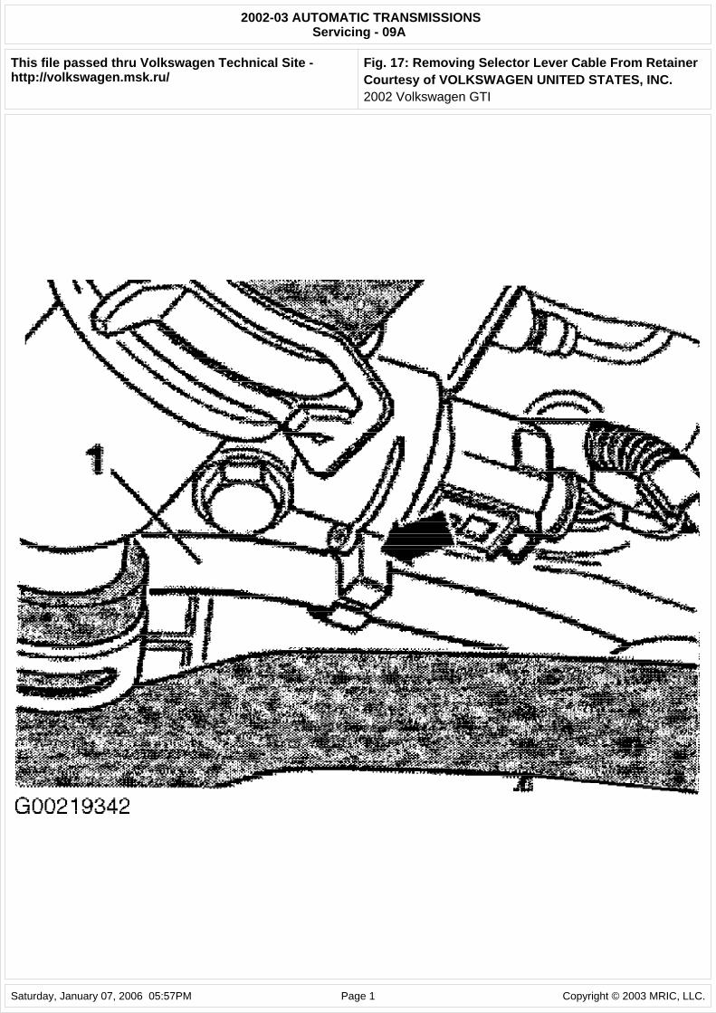
1. To remove cable, shift selector lever into "P" position. Pull selector lever cable (1) upward off lever/selector shaft (4). See Fig. 9. Remove circlip (3) at support bracket. Remove selector lever cable (1) from retainer (arrow) on engine. See Fig. 17. Raise and support vehicle. Unbolt retainer from catalytic converter on subframe and pull to rear. Loosen double clip. Do not remove catalytic converter. Leave on subframe.
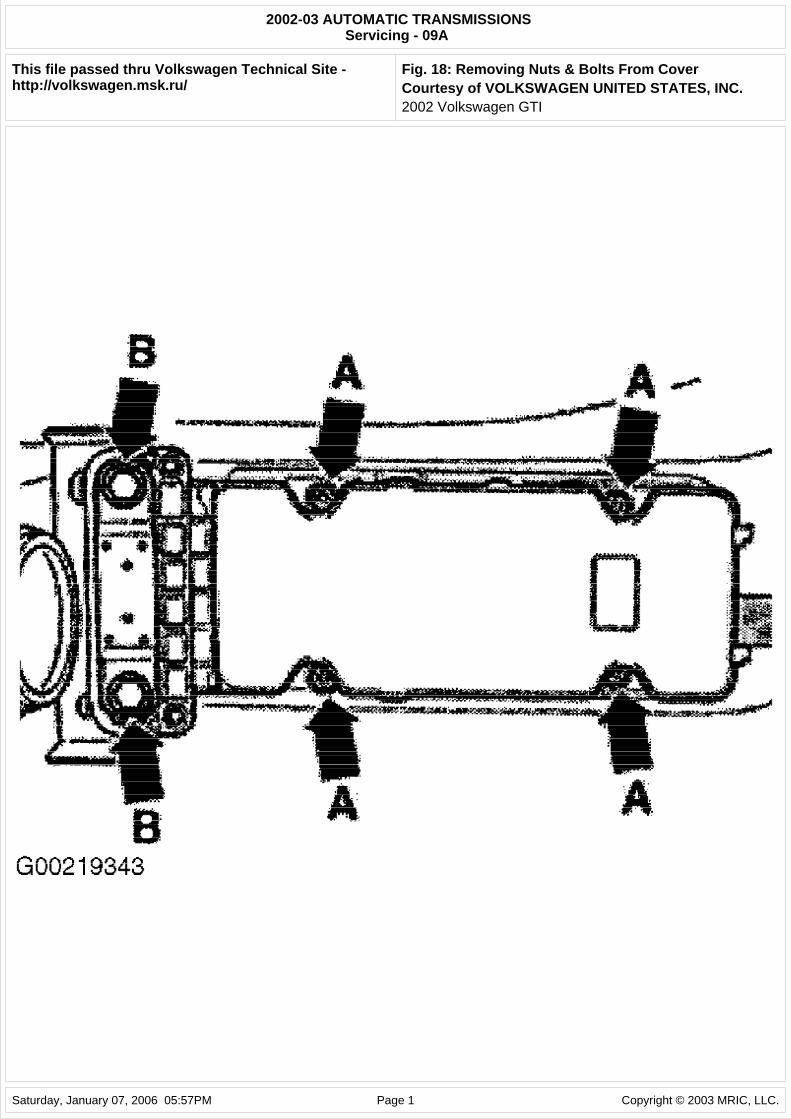
2. Remove selector lever from retainer on front heat shield. Remove front tunnel heat shield. Loosen center tunnel heat shield and slide to rear. Unscrew 4 nuts (arrows A) and 2 bolts (arrows B). See Fig. 18. Carefully slide cover with protective sleeve to front over selector lever cable. Be careful not to damage protective sleeve.
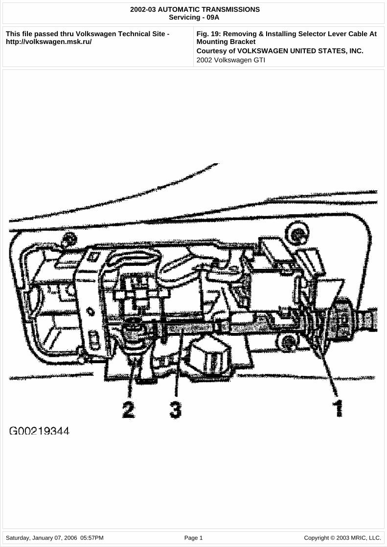
3. Pry selector lever cable (3) off selector lever (2) using a screwdriver. Pull out selector lever cable locking plate (1) on mounting bracket downward. See Fig. 19. Pull selector lever cable carefully out of mounting bracket.
4. To install cable, check protective sleeve for damage. Protective sleeve can only be changed together with selector lever cable. Check that protective sleeve is correctly fitted. Do not install protective sleeve twisted. Do not bend or kink the selector lever cable. Ensure that when selector lever and lever/selector shaft are in "P" position, front wheels are blocked.
5. Insert selector lever cable (3) in mounting bracket and press onto selector lever (2). Install NEW selector lever cable locking plate (1) on mounting bracket. See Fig. 19. Ensure angled end of locking plate points toward end of selector lever cable.
6. Shift selector lever from "P" to "2" position. Selector lever mechanism and selector lever cable must move freely. If necessary, replace selector lever cable or service selector lever mechanism. Shift selector lever into "P" position. Tighten cover with bonded seal to mounting bracket. Ensure the seal remains seated correctly.
7. Tighten 4 nuts (arrows A) to 89 INCH lbs. (10 N.m). Tighten 2 bolts (arrows B) to 18 ft. lbs. (25 N.m). Insert protective sleeve of selector lever cable in cover. Install front and center tunnel heat shields.
8. Install selector lever cable in bracket on front heat shield. Reconnect exhaust system. Install selector
NOTE: In the following procedures, numbers in parenthesis are shown in illustrations.
2002 Volkswagen GTI
lever cable (1) in retainer (arrow) on engine. See Fig. 17. Loosen bolt (2) at front ball socket of selector lever cable (1). Place selector lever cable in support bracket/transaxle and push onto lever/selector shaft (4) using a pair of pliers. See Fig. 9.
9. Install NEW circlip (3) to selector lever cable at support bracket/transaxle. See Fig. 9. Tighten bolt (2) to 115 INCH lbs. (13 N.m). Check selector mechanism operation.
Fig. 17: Removing Selector Lever Cable From Retainer Courtesy of VOLKSWAGEN UNITED STATES, INC.
Fig. 18: Removing Nuts & Bolts From Cover Courtesy of VOLKSWAGEN UNITED STATES, INC.
Fig. 19: Removing & Installing Selector Lever Cable At Mounting Bracket Courtesy of VOLKSWAGEN UNITED STATES, INC.
SELECTOR MECHANISM
Removal & Installation
1. To remove, shift selector lever into "P" position. Ensure ignition switch is off. Disconnect negative battery cable. Remove selector lever handle. Remove center console. Disconnect locking cable from the selector mechanism locking lever. See LOCKING CABLE .
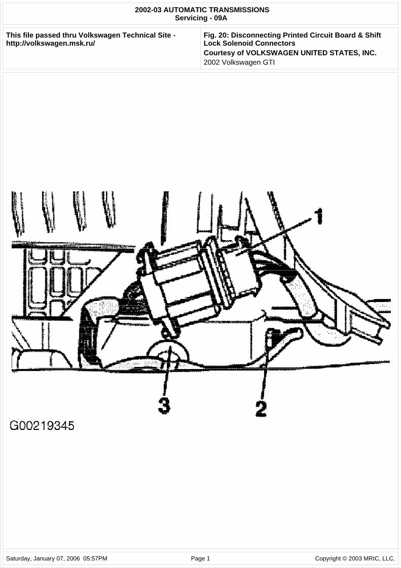
2. Separate printed circuit board connection (1). Using a screwdriver, carefully pry retainer (3) for shift lock solenoid connector (2) out of selector lever bracket. Separate shift lock solenoid connector (2). See Fig. 20.
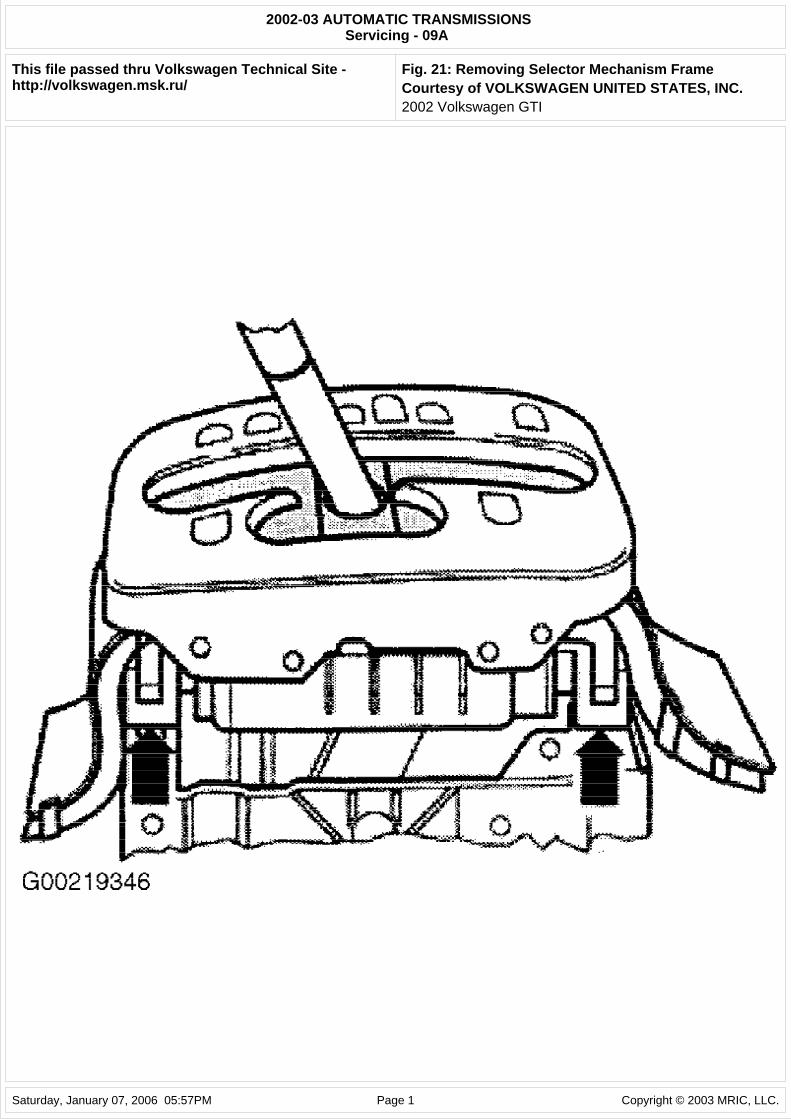
3. Carefully pry off frame at 4 corners (arrows) and remove. See Fig. 21. Remove 2 front selector mechanism securing nuts. Pull selector lever cable (1) upward off lever/selector shaft (4). Remove circlip (3) at support bracket. See Fig. 9.
4. Remove selector lever cable (1) from retainer (arrow) on engine. See Fig. 17. Raise and support vehicle. Unbolt retainer from catalytic converter on subframe and pull to rear. Loosen double clip. Do not remove catalytic converter. Leave on subframe. Remove selector lever from retainer on front heat shield. Remove front tunnel heat shield. Loosen center tunnel heat shield and slide to rear.
5. Unscrew 4 nuts (arrows A) and 2 bolts (arrows B). See Fig. 18. Carefully slide cover with protective sleeve to front over selector lever cable. Be careful not to damage protective sleeve.
6. Pry selector lever cable (3) off selector lever (2) using a screwdriver. Pull out selector lever cable locking plate (1) on mounting bracket downward. See Fig. 19. Pull selector lever cable carefully out of mounting bracket. Remove selector mechanism completely out of tunnel.
7. To install, check protective sleeve for damage. Protective sleeve can only be changed together with selector lever cable. Check that protective sleeve is correctly fitted. Do not install protective sleeve twisted. Do not bend or kink the selector lever cable.
8. Ensure selector lever and lever/selector shaft are in "P" position, and the front wheels are blocked. Insert selector lever cable (3) in mounting bracket and press onto selector lever (2). Install NEW
NOTE: In the following procedures, letters and numbers in parenthesis are shown in illustrations.
NOTE: When battery is disconnected, vehicle computer and memory systems may lose memory data. Driveability problems may exist until computer systems have completed a relearn cycle.
CAUTION: Radio/cassette or radio/CD player is equipped with an anti-theft protection circuit. Whenever battery is disconnected, radio will go into anti-theft mode. When battery is reconnected, radio will display CODE, and will be inoperative until proper code number is entered. Obtain security code before disconnecting battery.
2002 Volkswagen GTI
selector lever cable locking plate (1) on mounting bracket. See Fig. 19. Ensure angled end of locking plate points toward end of selector lever cable.
9. Insert complete selector mechanism with selector lever cable in tunnel underside. Tighten front of selector mechanism (2 nuts) to 18 ft. lbs. (25 N.m). Shift selector lever from "P" to "2" position. Selector lever mechanism and selector lever cable must move freely. If necessary, replace selector lever cable or service selector lever mechanism. Shift selector lever into "P" position.
10. Tighten 4 nuts (arrows A) to 89 INCH lbs. (10 N.m). Tighten 2 bolts (arrows B) to 18 ft. lbs. (25 N.m). See Fig. 18. When installing cover, ensure seal remains seated correctly. Insert protective sleeve of selector lever cable in cover. Install front and center tunnel heat shields. Fit selector lever cable in bracket on front heat shield. Reconnect exhaust system.
11. Fit selector lever cable (1) in retainer (arrow) on engine. See Fig. 17. Loosen bolt (2) at front ball socket of selector lever cable (1). Place selector lever cable in support bracket/transaxle and push onto lever/selector shaft (4) using a pair of pliers. Install NEW circlip (3) to selector lever cable at support bracket/transaxle. See Fig. 9.
12. Carefully position frame on 4 corners (arrows) and lock in. See Fig. 21. Connect shift lock solenoid connector (2). Insert retainer (3) for shift lock solenoid connector in selector lever bracket. Connect printed circuit board connector (1). See Fig. 20. Hook locking cable into locking lever of selector mechanism.
13. Adjust locking cable. See LOCKING CABLE under ADJUSTMENTS. Check ignition key operation. Install center console. Install selector lever handle. Reconnect negative battery cable. Adjust selector lever cable. See SELECTOR LEVER CABLE under ADJUSTMENTS. Check selector mechanism operation
Fig. 20: Disconnecting Printed Circuit Board & Shift Lock Solenoid Connectors Courtesy of VOLKSWAGEN UNITED STATES, INC.
Fig. 21: Removing Selector Mechanism Frame Courtesy of VOLKSWAGEN UNITED STATES, INC.
SELECTOR SHAFT OIL SEAL
Removal & Installation
1. Turn ignition switch off and disconnect negative battery cable. Remove battery. Remove battery carrier. Shift selector lever into "P" position.
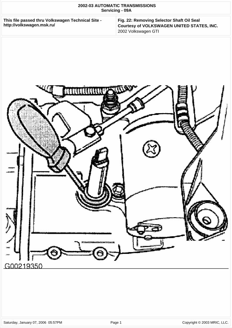
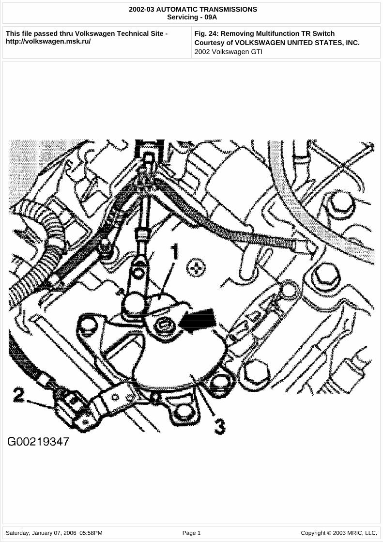
2. Remove nut (arrow) on selector shaft securing multifunction TR switch. Pull lever (1) off selector shaft. Disconnect multifunction TR switch connector (2). Remove multifunction TR switch (3). See Fig. 24. Pry oil seal out using a screwdriver. Do not damage selector shaft. See Fig. 22.
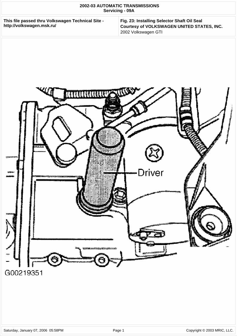
3. Drive in NEW seal until thrust driver contacts stop. See Fig. 23. Ensure that seal remains straight when installed. Install multifunction TR switch (3). Fit connector (2) to multifunction TR switch. Push lever (1) onto selector shaft. See Fig. 24. Shift selector lever from "P" to "2" position. Install selector shaft nut and tighten to 15 ft. lbs. (20 N.m).
NOTE: In the following procedures, numbers in parenthesis are shown in illustrations.
NOTE: When battery is disconnected, vehicle computer and memory systems may lose memory data. Driveability problems may exist until computer systems have completed a relearn cycle.
CAUTION: Radio/cassette or radio/CD player is equipped with an anti-theft protection circuit. Whenever battery is disconnected, radio will go into anti-theft mode. When battery is reconnected, radio will display CODE, and will be inoperative until proper code number is entered. Obtain security code before disconnecting battery.
2002 Volkswagen GTI
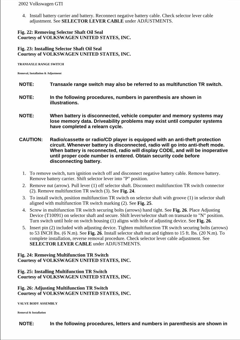
4. Install battery carrier and battery. Reconnect negative battery cable. Check selector lever cable adjustment. See SELECTOR LEVER CABLE under ADJUSTMENTS.
Fig. 22: Removing Selector Shaft Oil Seal Courtesy of VOLKSWAGEN UNITED STATES, INC.
Fig. 23: Installing Selector Shaft Oil Seal Courtesy of VOLKSWAGEN UNITED STATES, INC.
TRANSAXLE RANGE SWITCH
Removal, Installation & Adjustment
1. To remove switch, turn ignition switch off and disconnect negative battery cable. Remove battery. Remove battery carrier. Shift selector lever into "P" position.
2. Remove nut (arrow). Pull lever (1) off selector shaft. Disconnect multifunction TR switch connector (2). Remove multifunction TR switch (3). See Fig. 24.
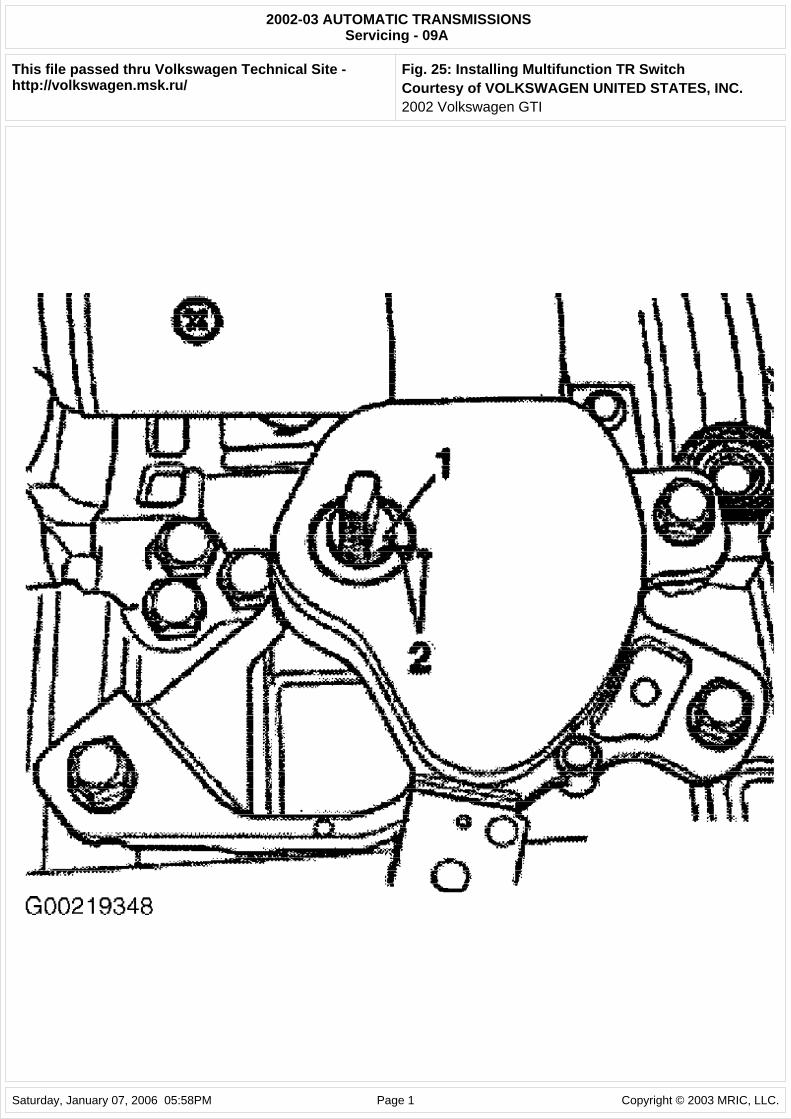
3. To install switch, position multifunction TR switch on selector shaft with groove (1) in selector shaft aligned with multifunction TR switch marking (2). See Fig. 25.
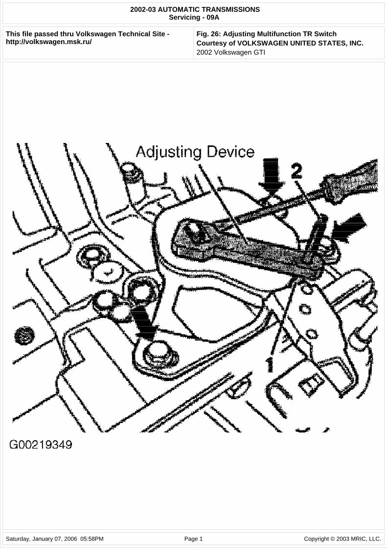
4. Screw in multifunction TR switch securing bolts (arrows) hand tight. See Fig. 26. Place Adjusting Device (T10091) on selector shaft and secure. Shift lever/selector shaft on transaxle to "N" position. Turn switch until hole on switch housing (1) aligns with hole of adjusting device. See Fig. 26.
5. Insert pin (2) included with adjusting device. Tighten multifunction TR switch securing bolts (arrows) to 53 INCH lbs. (6 N.m). See Fig. 26. Install selector shaft nut and tighten to 15 ft. lbs. (20 N.m). To complete installation, reverse removal procedure. Check selector lever cable adjustment. See SELECTOR LEVER CABLE under ADJUSTMENTS.
Fig. 24: Removing Multifunction TR Switch Courtesy of VOLKSWAGEN UNITED STATES, INC.
Fig. 25: Installing Multifunction TR Switch Courtesy of VOLKSWAGEN UNITED STATES, INC.
Fig. 26: Adjusting Multifunction TR Switch Courtesy of VOLKSWAGEN UNITED STATES, INC.
VALVE BODY ASSEMBLY
Removal & Installation
NOTE: Transaxle range switch may also be referred to as multifunction TR switch.
NOTE: In the following procedures, numbers in parenthesis are shown in illustrations.
NOTE: When battery is disconnected, vehicle computer and memory systems may lose memory data. Driveability problems may exist until computer systems have completed a relearn cycle.
CAUTION: Radio/cassette or radio/CD player is equipped with an anti-theft protection circuit. Whenever battery is disconnected, radio will go into anti-theft mode. When battery is reconnected, radio will display CODE, and will be inoperative until proper code number is entered. Obtain security code before disconnecting battery.
NOTE: In the following procedures, letters and numbers in parenthesis are shown in
2002 Volkswagen GTI
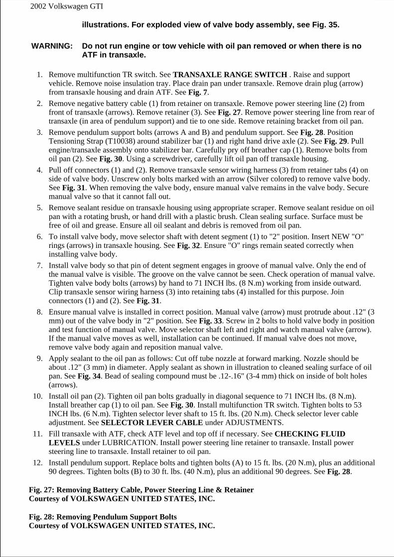
1. Remove multifunction TR switch. See TRANSAXLE RANGE SWITCH . Raise and support vehicle. Remove noise insulation tray. Place drain pan under transaxle. Remove drain plug (arrow) from transaxle housing and drain ATF. See Fig. 7.
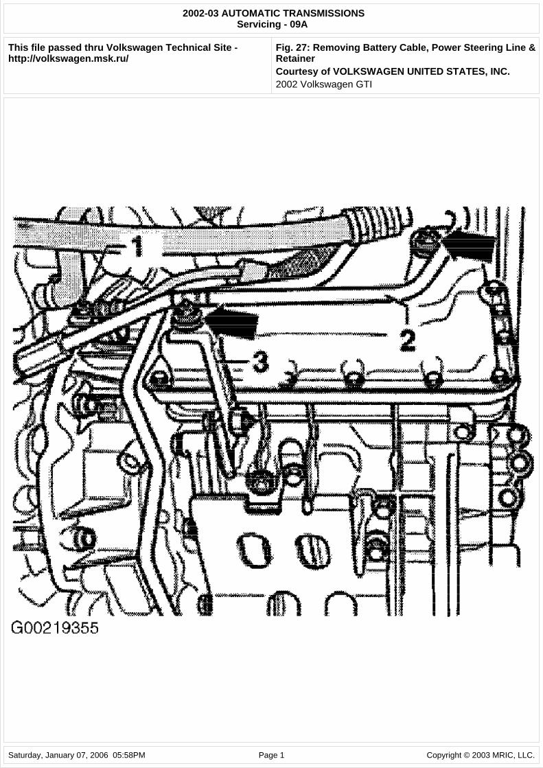
2. Remove negative battery cable (1) from retainer on transaxle. Remove power steering line (2) from front of transaxle (arrows). Remove retainer (3). See Fig. 27. Remove power steering line from rear of transaxle (in area of pendulum support) and tie to one side. Remove retaining bracket from oil pan.
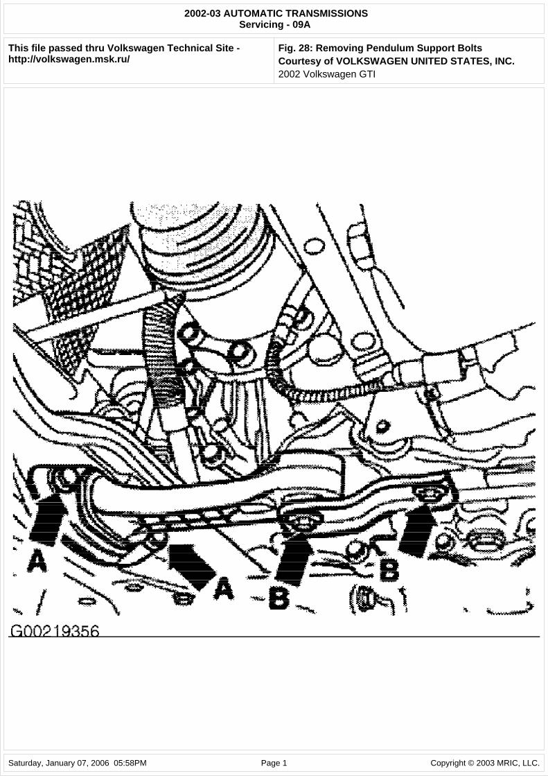
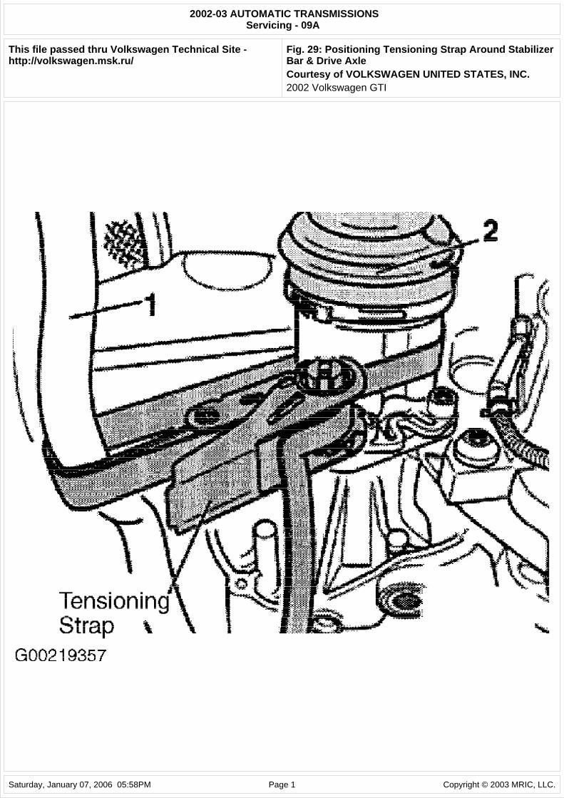
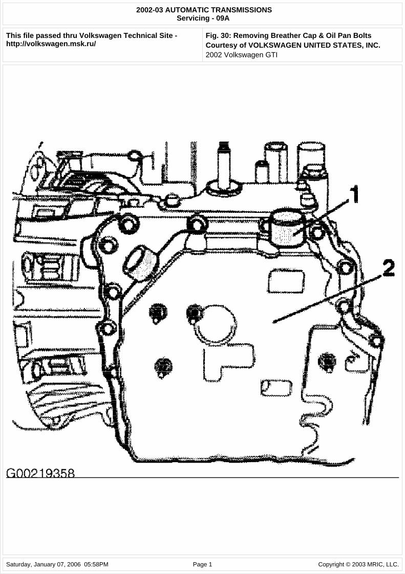
3. Remove pendulum support bolts (arrows A and B) and pendulum support. See Fig. 28. Position Tensioning Strap (T10038) around stabilizer bar (1) and right hand drive axle (2). See Fig. 29. Pull engine/transaxle assembly onto stabilizer bar. Carefully pry off breather cap (1). Remove bolts from oil pan (2). See Fig. 30. Using a screwdriver, carefully lift oil pan off transaxle housing.
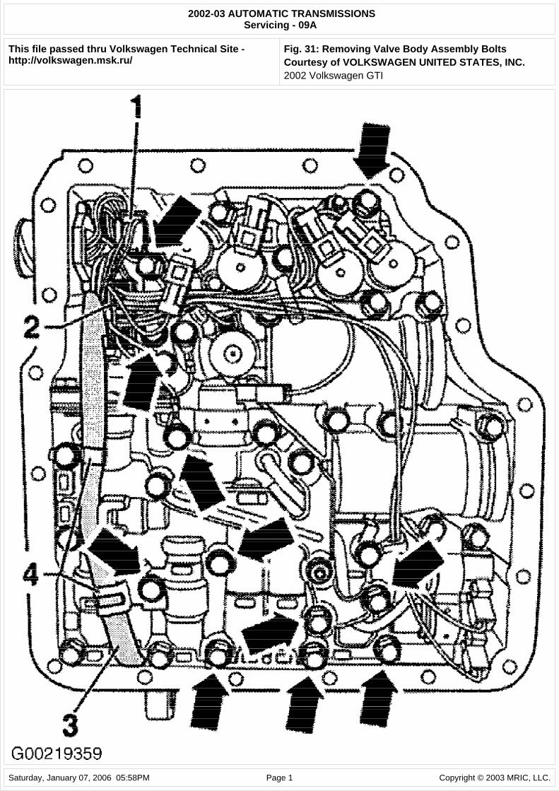
4. Pull off connectors (1) and (2). Remove transaxle sensor wiring harness (3) from retainer tabs (4) on side of valve body. Unscrew only bolts marked with an arrow (Silver colored) to remove valve body. See Fig. 31. When removing the valve body, ensure manual valve remains in the valve body. Secure manual valve so that it cannot fall out.
5. Remove sealant residue on transaxle housing using appropriate scraper. Remove sealant residue on oil pan with a rotating brush, or hand drill with a plastic brush. Clean sealing surface. Surface must be free of oil and grease. Ensure all oil sealant and debris is removed from oil pan.
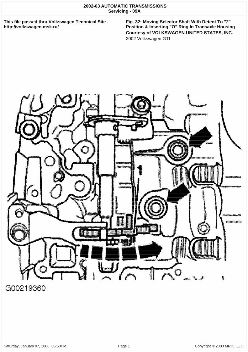
6. To install valve body, move selector shaft with detent segment (1) to "2" position. Insert NEW "O" rings (arrows) in transaxle housing. See Fig. 32. Ensure "O" rings remain seated correctly when installing valve body.
7. Install valve body so that pin of detent segment engages in groove of manual valve. Only the end of the manual valve is visible. The groove on the valve cannot be seen. Check operation of manual valve. Tighten valve body bolts (arrows) by hand to 71 INCH lbs. (8 N.m) working from inside outward. Clip transaxle sensor wiring harness (3) into retaining tabs (4) installed for this purpose. Join connectors (1) and (2). See Fig. 31.
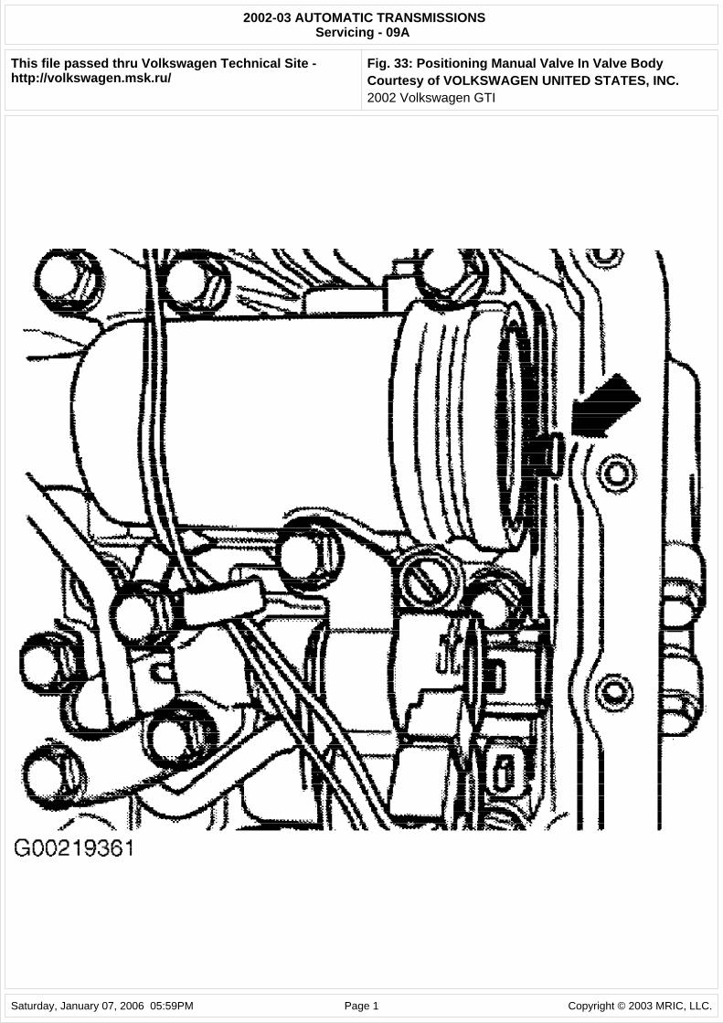
8. Ensure manual valve is installed in correct position. Manual valve (arrow) must protrude about .12" (3 mm) out of the valve body in "2" position. See Fig. 33. Screw in 2 bolts to hold valve body in position and test function of manual valve. Move selector shaft left and right and watch manual valve (arrow). If the manual valve moves as well, installation can be continued. If manual valve does not move, remove valve body again and reposition manual valve.
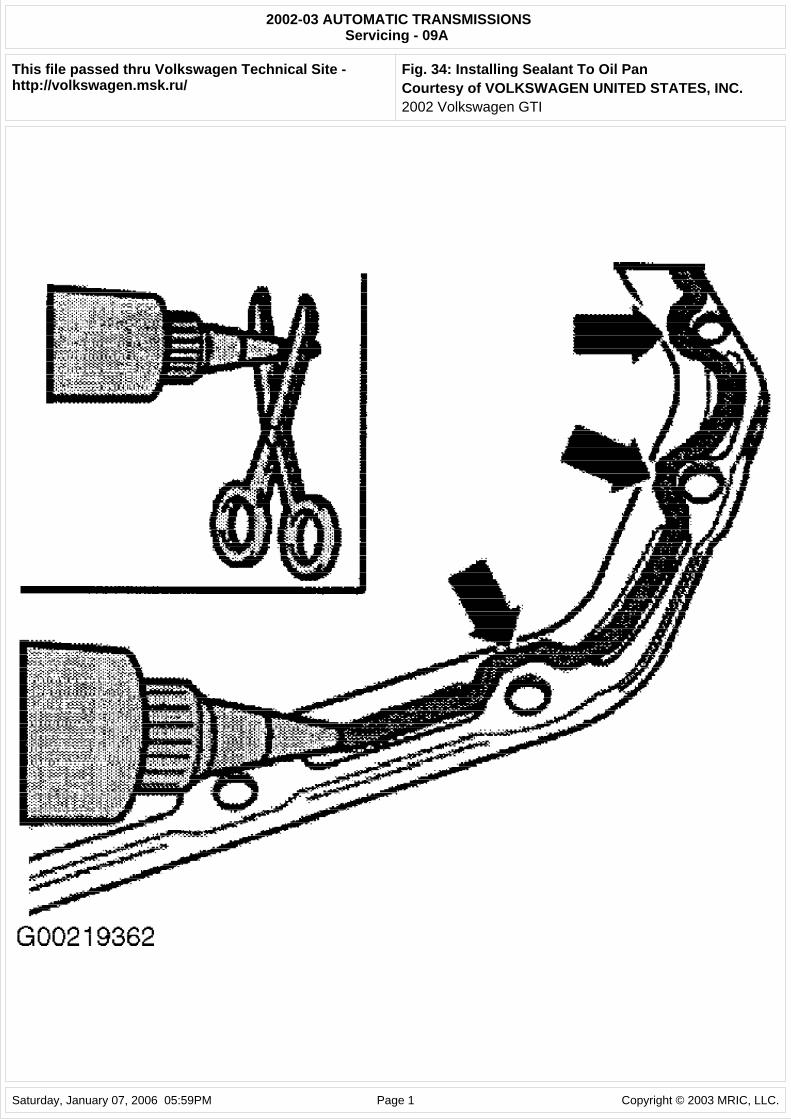
9. Apply sealant to the oil pan as follows: Cut off tube nozzle at forward marking. Nozzle should be about .12" (3 mm) in diameter. Apply sealant as shown in illustration to cleaned sealing surface of oil pan. See Fig. 34. Bead of sealing compound must be .12-.16" (3-4 mm) thick on inside of bolt holes (arrows).
10. Install oil pan (2). Tighten oil pan bolts gradually in diagonal sequence to 71 INCH lbs. (8 N.m). Install breather cap (1) to oil pan. See Fig. 30. Install multifunction TR switch. Tighten bolts to 53 INCH lbs. (6 N.m). Tighten selector lever shaft to 15 ft. lbs. (20 N.m). Check selector lever cable adjustment. See SELECTOR LEVER CABLE under ADJUSTMENTS.
11. Fill transaxle with ATF, check ATF level and top off if necessary. See CHECKING FLUID LEVELS under LUBRICATION. Install power steering line retainer to transaxle. Install power steering line to transaxle. Install retainer to oil pan.
12. Install pendulum support. Replace bolts and tighten bolts (A) to 15 ft. lbs. (20 N.m), plus an additional 90 degrees. Tighten bolts (B) to 30 ft. lbs. (40 N.m), plus an additional 90 degrees. See Fig. 28.
Fig. 27: Removing Battery Cable, Power Steering Line & Retainer Courtesy of VOLKSWAGEN UNITED STATES, INC.
Fig. 28: Removing Pendulum Support Bolts Courtesy of VOLKSWAGEN UNITED STATES, INC.
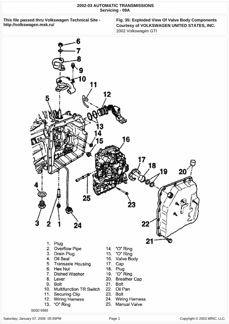
illustrations. For exploded view of valve body assembly, see Fig. 35.
WARNING: Do not run engine or tow vehicle with oil pan removed or when there is no ATF in transaxle.
2002 Volkswagen GTI
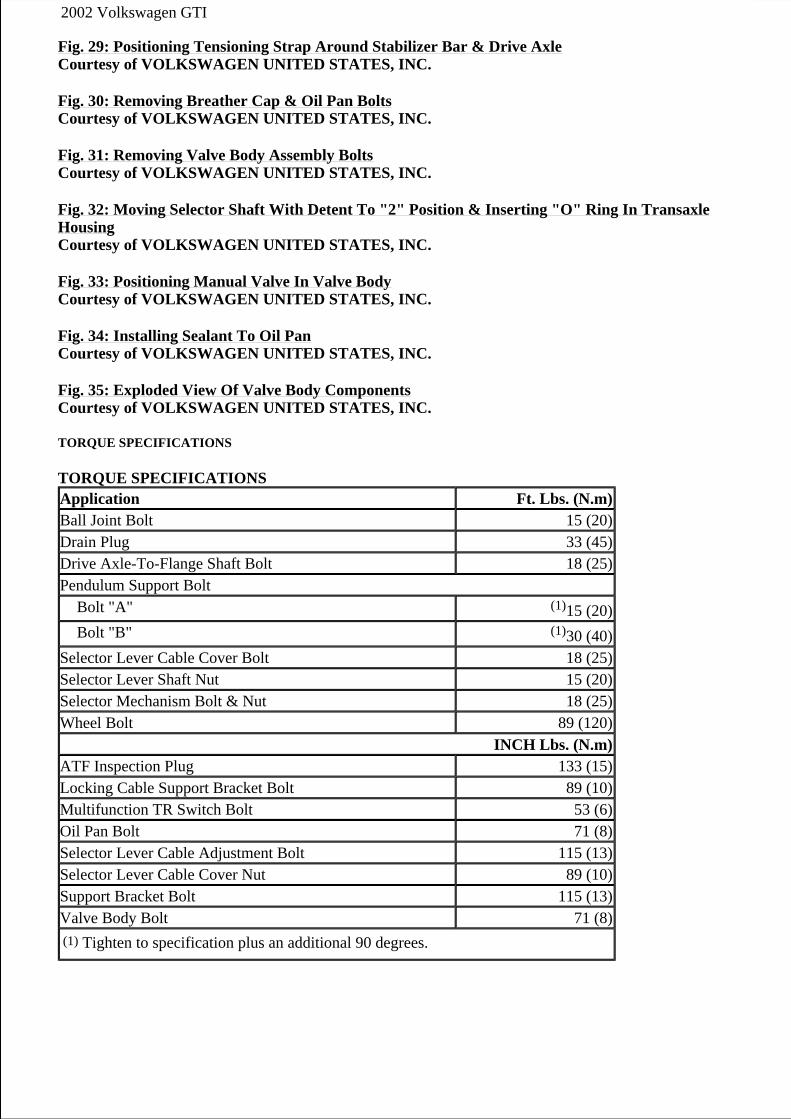
Fig. 29: Positioning Tensioning Strap Around Stabilizer Bar & Drive Axle Courtesy of VOLKSWAGEN UNITED STATES, INC.
Fig. 30: Removing Breather Cap & Oil Pan Bolts Courtesy of VOLKSWAGEN UNITED STATES, INC.
Fig. 31: Removing Valve Body Assembly Bolts Courtesy of VOLKSWAGEN UNITED STATES, INC.
Fig. 32: Moving Selector Shaft With Detent To "2" Position & Inserting "O" Ring In Transaxle Housing Courtesy of VOLKSWAGEN UNITED STATES, INC.
Fig. 33: Positioning Manual Valve In Valve Body Courtesy of VOLKSWAGEN UNITED STATES, INC.
Fig. 34: Installing Sealant To Oil Pan Courtesy of VOLKSWAGEN UNITED STATES, INC.
Fig. 35: Exploded View Of Valve Body Components Courtesy of VOLKSWAGEN UNITED STATES, INC.
TORQUE SPECIFICATIONS
TORQUE SPECIFICATIONS Application Ft. Lbs. (N.m) Ball Joint Bolt 15 (20) Drain Plug 33 (45) Drive Axle-To-Flange Shaft Bolt 18 (25) Pendulum Support Bolt
Bolt "A" (1)15 (20) Bolt "B" (1)30 (40)
Selector Lever Cable Cover Bolt 18 (25) Selector Lever Shaft Nut 15 (20) Selector Mechanism Bolt & Nut 18 (25) Wheel Bolt 89 (120)
INCH Lbs. (N.m)ATF Inspection Plug 133 (15) Locking Cable Support Bracket Bolt 89 (10) Multifunction TR Switch Bolt 53 (6) Oil Pan Bolt 71 (8) Selector Lever Cable Adjustment Bolt 115 (13) Selector Lever Cable Cover Nut 89 (10) Support Bracket Bolt 115 (13) Valve Body Bolt 71 (8) (1) Tighten to specification plus an additional 90 degrees.
2002 Volkswagen GTI
2002-03 AUTOMATIC TRANSMISSIONSServicing - 09A
This file passed thru Volkswagen Technical Site - http://volkswagen.msk.ru/
Fig. 1: Identifying Oil Pan Gasket (09A)Courtesy of VOLKSWAGEN UNITED STATES, INC.2002 Volkswagen GTI
Saturday, January 07, 2006 05:55PM Page 1 Copyright © 2003 MRIC, LLC.
2002-03 AUTOMATIC TRANSMISSIONSServicing - 09A
This file passed thru Volkswagen Technical Site - http://volkswagen.msk.ru/
Fig. 2: Removing ATF Inspection PlugCourtesy of VOLKSWAGEN UNITED STATES, INC.2002 Volkswagen GTI
Saturday, January 07, 2006 05:55PM Page 1 Copyright © 2003 MRIC, LLC.
2002-03 AUTOMATIC TRANSMISSIONSServicing - 09A
This file passed thru Volkswagen Technical Site - http://volkswagen.msk.ru/
Fig. 3: Locating Inspection Plug Seal & Overflow PipeCourtesy of VOLKSWAGEN UNITED STATES, INC.2002 Volkswagen GTI
Saturday, January 07, 2006 05:55PM Page 1 Copyright © 2003 MRIC, LLC.
2002-03 AUTOMATIC TRANSMISSIONSServicing - 09A
This file passed thru Volkswagen Technical Site - http://volkswagen.msk.ru/
Fig. 4: Prying Off Plug Securing CapCourtesy of VOLKSWAGEN UNITED STATES, INC.2002 Volkswagen GTI
Saturday, January 07, 2006 05:55PM Page 1 Copyright © 2003 MRIC, LLC.
2002-03 AUTOMATIC TRANSMISSIONSServicing - 09A
This file passed thru Volkswagen Technical Site - http://volkswagen.msk.ru/
Fig. 5: Filling Transaxle With ATF Using VAG 1924 FillingSystemCourtesy of VOLKSWAGEN UNITED STATES, INC.2002 Volkswagen GTI
Saturday, January 07, 2006 05:55PM Page 1 Copyright © 2003 MRIC, LLC.
2002-03 AUTOMATIC TRANSMISSIONSServicing - 09A
This file passed thru Volkswagen Technical Site - http://volkswagen.msk.ru/
Fig. 6: Installing Cap To Filler Pipe PlugCourtesy of VOLKSWAGEN UNITED STATES, INC.2002 Volkswagen GTI
Saturday, January 07, 2006 05:55PM Page 1 Copyright © 2003 MRIC, LLC.
2002-03 AUTOMATIC TRANSMISSIONSServicing - 09A
This file passed thru Volkswagen Technical Site - http://volkswagen.msk.ru/
Fig. 7: Removing Drain Plug From Transaxle HousingCourtesy of VOLKSWAGEN UNITED STATES, INC.2002 Volkswagen GTI
Saturday, January 07, 2006 05:56PM Page 1 Copyright © 2003 MRIC, LLC.
2002-03 AUTOMATIC TRANSMISSIONSServicing - 09A
This file passed thru Volkswagen Technical Site - http://volkswagen.msk.ru/
Fig. 8: Adjusting Locking CableCourtesy of VOLKSWAGEN UNITED STATES, INC.2002 Volkswagen GTI
Saturday, January 07, 2006 05:56PM Page 1 Copyright © 2003 MRIC, LLC.
2002-03 AUTOMATIC TRANSMISSIONSServicing - 09A
This file passed thru Volkswagen Technical Site - http://volkswagen.msk.ru/
Fig. 9: Removing Selector Lever Cable From Lever/Selector ShaftCourtesy of VOLKSWAGEN UNITED STATES, INC.2002 Volkswagen GTI
Saturday, January 07, 2006 05:56PM Page 1 Copyright © 2003 MRIC, LLC.
2002-03 AUTOMATIC TRANSMISSIONSServicing - 09A
This file passed thru Volkswagen Technical Site - http://volkswagen.msk.ru/
Fig. 10: Positioning Left Drive AxleCourtesy of VOLKSWAGEN UNITED STATES, INC.2002 Volkswagen GTI
Saturday, January 07, 2006 05:56PM Page 1 Copyright © 2003 MRIC, LLC.
2002-03 AUTOMATIC TRANSMISSIONSServicing - 09A
This file passed thru Volkswagen Technical Site - http://volkswagen.msk.ru/
Fig. 11: Removing Left Flanged Shaft Oil SealCourtesy of VOLKSWAGEN UNITED STATES, INC.2002 Volkswagen GTI
Saturday, January 07, 2006 05:56PM Page 1 Copyright © 2003 MRIC, LLC.
2002-03 AUTOMATIC TRANSMISSIONSServicing - 09A
This file passed thru Volkswagen Technical Site - http://volkswagen.msk.ru/
Fig. 12: Removing & Installing Sound Insulation TrayCourtesy of VOLKSWAGEN UNITED STATES, INC.2002 Volkswagen GTI
Saturday, January 07, 2006 05:56PM Page 1 Copyright © 2003 MRIC, LLC.
2002-03 AUTOMATIC TRANSMISSIONSServicing - 09A
This file passed thru Volkswagen Technical Site - http://volkswagen.msk.ru/
Fig. 13: Identifying Installation Position Of Locking CableCourtesy of VOLKSWAGEN UNITED STATES, INC.2002 Volkswagen GTI
Saturday, January 07, 2006 05:56PM Page 1 Copyright © 2003 MRIC, LLC.
2002-03 AUTOMATIC TRANSMISSIONSServicing - 09A
This file passed thru Volkswagen Technical Site - http://volkswagen.msk.ru/
Fig. 14: Removing Locking Cable From Steering LockCourtesy of VOLKSWAGEN UNITED STATES, INC.2002 Volkswagen GTI
Saturday, January 07, 2006 05:56PM Page 1 Copyright © 2003 MRIC, LLC.
2002-03 AUTOMATIC TRANSMISSIONSServicing - 09A
This file passed thru Volkswagen Technical Site - http://volkswagen.msk.ru/
Fig. 15: Removing Locking CableCourtesy of VOLKSWAGEN UNITED STATES, INC.2002 Volkswagen GTI
Saturday, January 07, 2006 05:57PM Page 1 Copyright © 2003 MRIC, LLC.
2002-03 AUTOMATIC TRANSMISSIONSServicing - 09A
This file passed thru Volkswagen Technical Site - http://volkswagen.msk.ru/
Fig. 16: Guiding Locking Cable Between Heater & Footwell VentsCourtesy of VOLKSWAGEN UNITED STATES, INC.2002 Volkswagen GTI
Saturday, January 07, 2006 05:57PM Page 1 Copyright © 2003 MRIC, LLC.
2002-03 AUTOMATIC TRANSMISSIONSServicing - 09A
This file passed thru Volkswagen Technical Site - http://volkswagen.msk.ru/
Fig. 17: Removing Selector Lever Cable From RetainerCourtesy of VOLKSWAGEN UNITED STATES, INC.2002 Volkswagen GTI
Saturday, January 07, 2006 05:57PM Page 1 Copyright © 2003 MRIC, LLC.
2002-03 AUTOMATIC TRANSMISSIONSServicing - 09A
This file passed thru Volkswagen Technical Site - http://volkswagen.msk.ru/
Fig. 18: Removing Nuts & Bolts From CoverCourtesy of VOLKSWAGEN UNITED STATES, INC.2002 Volkswagen GTI
Saturday, January 07, 2006 05:57PM Page 1 Copyright © 2003 MRIC, LLC.
2002-03 AUTOMATIC TRANSMISSIONSServicing - 09A
This file passed thru Volkswagen Technical Site - http://volkswagen.msk.ru/
Fig. 19: Removing & Installing Selector Lever Cable At Mounting BracketCourtesy of VOLKSWAGEN UNITED STATES, INC.2002 Volkswagen GTI
Saturday, January 07, 2006 05:57PM Page 1 Copyright © 2003 MRIC, LLC.
2002-03 AUTOMATIC TRANSMISSIONSServicing - 09A
This file passed thru Volkswagen Technical Site - http://volkswagen.msk.ru/
Fig. 20: Disconnecting Printed Circuit Board & Shift Lock Solenoid ConnectorsCourtesy of VOLKSWAGEN UNITED STATES, INC.2002 Volkswagen GTI
Saturday, January 07, 2006 05:57PM Page 1 Copyright © 2003 MRIC, LLC.
2002-03 AUTOMATIC TRANSMISSIONSServicing - 09A
This file passed thru Volkswagen Technical Site - http://volkswagen.msk.ru/
Fig. 21: Removing Selector Mechanism FrameCourtesy of VOLKSWAGEN UNITED STATES, INC.2002 Volkswagen GTI
Saturday, January 07, 2006 05:57PM Page 1 Copyright © 2003 MRIC, LLC.
2002-03 AUTOMATIC TRANSMISSIONSServicing - 09A
This file passed thru Volkswagen Technical Site - http://volkswagen.msk.ru/
Fig. 22: Removing Selector Shaft Oil SealCourtesy of VOLKSWAGEN UNITED STATES, INC.2002 Volkswagen GTI
Saturday, January 07, 2006 05:57PM Page 1 Copyright © 2003 MRIC, LLC.
2002-03 AUTOMATIC TRANSMISSIONSServicing - 09A
This file passed thru Volkswagen Technical Site - http://volkswagen.msk.ru/
Fig. 23: Installing Selector Shaft Oil SealCourtesy of VOLKSWAGEN UNITED STATES, INC.2002 Volkswagen GTI
Saturday, January 07, 2006 05:58PM Page 1 Copyright © 2003 MRIC, LLC.
2002-03 AUTOMATIC TRANSMISSIONSServicing - 09A
This file passed thru Volkswagen Technical Site - http://volkswagen.msk.ru/
Fig. 24: Removing Multifunction TR SwitchCourtesy of VOLKSWAGEN UNITED STATES, INC.2002 Volkswagen GTI
Saturday, January 07, 2006 05:58PM Page 1 Copyright © 2003 MRIC, LLC.
2002-03 AUTOMATIC TRANSMISSIONSServicing - 09A
This file passed thru Volkswagen Technical Site - http://volkswagen.msk.ru/
Fig. 25: Installing Multifunction TR SwitchCourtesy of VOLKSWAGEN UNITED STATES, INC.2002 Volkswagen GTI
Saturday, January 07, 2006 05:58PM Page 1 Copyright © 2003 MRIC, LLC.
2002-03 AUTOMATIC TRANSMISSIONSServicing - 09A
This file passed thru Volkswagen Technical Site - http://volkswagen.msk.ru/
Fig. 26: Adjusting Multifunction TR SwitchCourtesy of VOLKSWAGEN UNITED STATES, INC.2002 Volkswagen GTI
Saturday, January 07, 2006 05:58PM Page 1 Copyright © 2003 MRIC, LLC.
2002-03 AUTOMATIC TRANSMISSIONSServicing - 09A
This file passed thru Volkswagen Technical Site - http://volkswagen.msk.ru/
Fig. 27: Removing Battery Cable, Power Steering Line & RetainerCourtesy of VOLKSWAGEN UNITED STATES, INC.2002 Volkswagen GTI
Saturday, January 07, 2006 05:58PM Page 1 Copyright © 2003 MRIC, LLC.
2002-03 AUTOMATIC TRANSMISSIONSServicing - 09A
This file passed thru Volkswagen Technical Site - http://volkswagen.msk.ru/
Fig. 28: Removing Pendulum Support BoltsCourtesy of VOLKSWAGEN UNITED STATES, INC.2002 Volkswagen GTI
Saturday, January 07, 2006 05:58PM Page 1 Copyright © 2003 MRIC, LLC.
2002-03 AUTOMATIC TRANSMISSIONSServicing - 09A
This file passed thru Volkswagen Technical Site - http://volkswagen.msk.ru/
Fig. 29: Positioning Tensioning Strap Around Stabilizer Bar & Drive AxleCourtesy of VOLKSWAGEN UNITED STATES, INC.2002 Volkswagen GTI
Saturday, January 07, 2006 05:58PM Page 1 Copyright © 2003 MRIC, LLC.
2002-03 AUTOMATIC TRANSMISSIONSServicing - 09A
This file passed thru Volkswagen Technical Site - http://volkswagen.msk.ru/
Fig. 30: Removing Breather Cap & Oil Pan BoltsCourtesy of VOLKSWAGEN UNITED STATES, INC.2002 Volkswagen GTI
Saturday, January 07, 2006 05:58PM Page 1 Copyright © 2003 MRIC, LLC.
2002-03 AUTOMATIC TRANSMISSIONSServicing - 09A
This file passed thru Volkswagen Technical Site - http://volkswagen.msk.ru/
Fig. 31: Removing Valve Body Assembly BoltsCourtesy of VOLKSWAGEN UNITED STATES, INC.2002 Volkswagen GTI
Saturday, January 07, 2006 05:58PM Page 1 Copyright © 2003 MRIC, LLC.
2002-03 AUTOMATIC TRANSMISSIONSServicing - 09A
This file passed thru Volkswagen Technical Site - http://volkswagen.msk.ru/
Fig. 32: Moving Selector Shaft With Detent To "2" Position & Inserting "O" Ring In Transaxle HousingCourtesy of VOLKSWAGEN UNITED STATES, INC.2002 Volkswagen GTI
Saturday, January 07, 2006 05:58PM Page 1 Copyright © 2003 MRIC, LLC.
2002-03 AUTOMATIC TRANSMISSIONSServicing - 09A
This file passed thru Volkswagen Technical Site - http://volkswagen.msk.ru/
Fig. 33: Positioning Manual Valve In Valve BodyCourtesy of VOLKSWAGEN UNITED STATES, INC.2002 Volkswagen GTI
Saturday, January 07, 2006 05:59PM Page 1 Copyright © 2003 MRIC, LLC.
2002-03 AUTOMATIC TRANSMISSIONSServicing - 09A
This file passed thru Volkswagen Technical Site - http://volkswagen.msk.ru/
Fig. 34: Installing Sealant To Oil PanCourtesy of VOLKSWAGEN UNITED STATES, INC.2002 Volkswagen GTI
Saturday, January 07, 2006 05:59PM Page 1 Copyright © 2003 MRIC, LLC.
2002-03 AUTOMATIC TRANSMISSIONSServicing - 09A
This file passed thru Volkswagen Technical Site - http://volkswagen.msk.ru/
Fig. 35: Exploded View Of Valve Body ComponentsCourtesy of VOLKSWAGEN UNITED STATES, INC.2002 Volkswagen GTI
Saturday, January 07, 2006 05:59PM Page 1 Copyright © 2003 MRIC, LLC.


