Embed Size (px)
Citation preview

ATM Technology in Detail
Professor Richard Harris
Semester 2 - 2005 Advanced Telecommunications 143.466 Slide 2
Objectives
• You should be able to:– Discuss the ATM protocol stack– Identify the different layers and their purpose– Explain the ATM Adaptation Layer– Discuss the key differences between ATM, Frame Relay and
IP technologies
Semester 2 - 2005 Advanced Telecommunications 143.466 Slide 3
Presentation Outline
• ATM Layering• Adaptation layers in more detail• Comparative reviews of
– ATM versus Frame Relay– ATM versus LAN technologies– ATM versus IP
Semester 2 - 2005 Advanced Telecommunications 143.466 Slide 4
ATM Layering - 1
• ATM Layering defined by BISDN Reference model
• Distinguish User, Control and Management planes
• Three layers of functionality– Physical– ATM– ATM Adaptation (AAL)

Semester 2 - 2005 Advanced Telecommunications 143.466 Slide 5
ATM Layering - 2
User PlaneControl Plane Management Plane
Q.2931 TCP/IPFTP, etc
LMI, SNMP,CMIP
AAL AAL
ATM
SDH, SONET,SDH, SONET,DS1, E1, etcDS1, E1, etc
SSCFSSCOPAALCPSA
AL
Examples of Protocol Placement in the BISDN layers
SSCOP - Service Specific Convergence Protocol
SSCF - Service Specific Convergence Function
AALCP - AAL Convergence Protocol
Semester 2 - 2005 Advanced Telecommunications 143.466 Slide 6
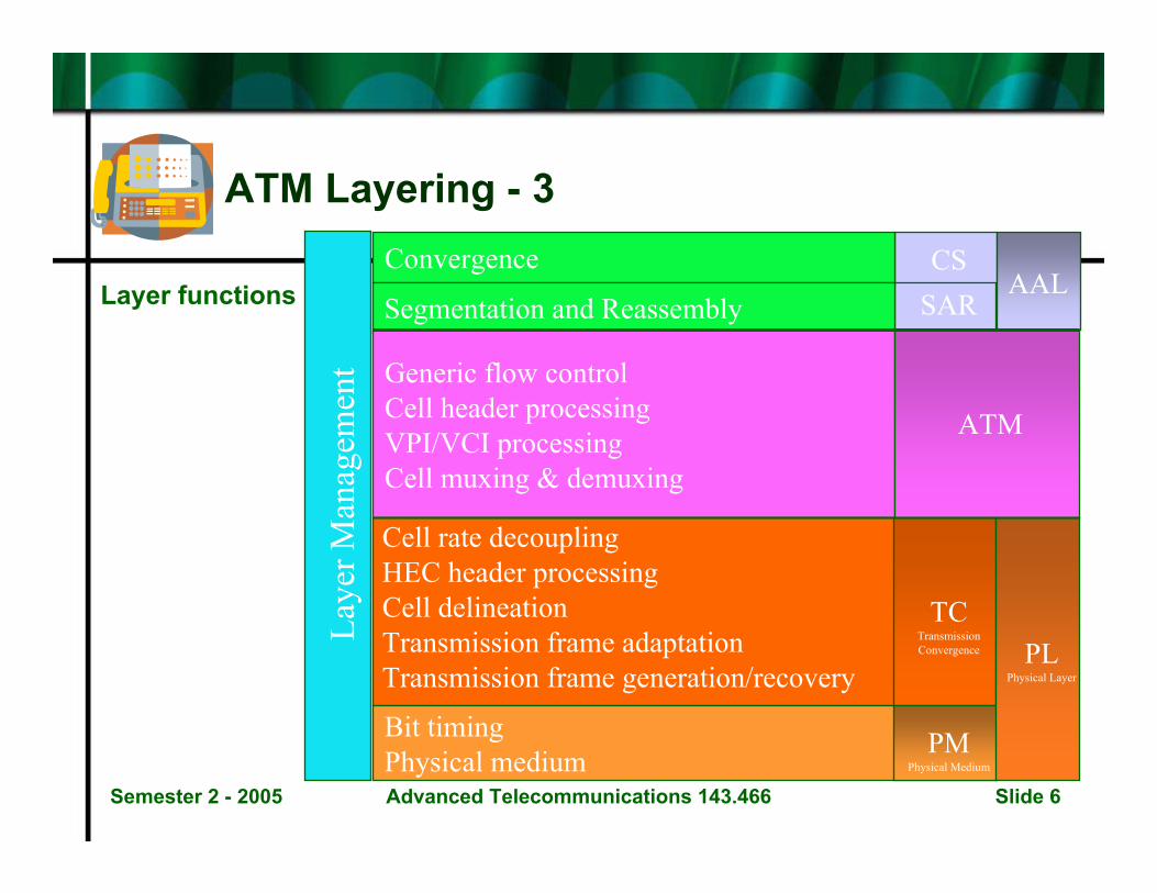
ATM Layering - 3 Convergence
Segmentation and Reassembly
Generic flow controlCell header processingVPI/VCI processingCell muxing & demuxing
Cell rate decouplingHEC header processingCell delineationTransmission frame adaptationTransmission frame generation/recovery
Bit timingPhysical medium
CSSAR
AAL
ATM
TCTransmissionConvergence
PMPhysical Medium
PLPhysical Layer
Laye
r Man
agem
ent
Layer functions
Semester 2 - 2005 Advanced Telecommunications 143.466 Slide 7
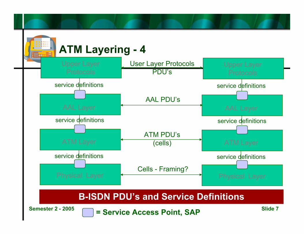
ATM Layering - 4
B-ISDN PDU’s and Service Definitions
Upper LayerProtocols
AAL Layer
ATM Layer
Physical Layer
service definitions
service definitions
service definitions
Upper LayerProtocols
AAL Layer
ATM Layer
Physical Layer
service definitions
service definitions
service definitions
User Layer ProtocolsPDU’s
AAL PDU’s
ATM PDU’s(cells)
Cells - Framing?
= Service Access Point, SAP
Semester 2 - 2005 Advanced Telecommunications 143.466 Slide 8
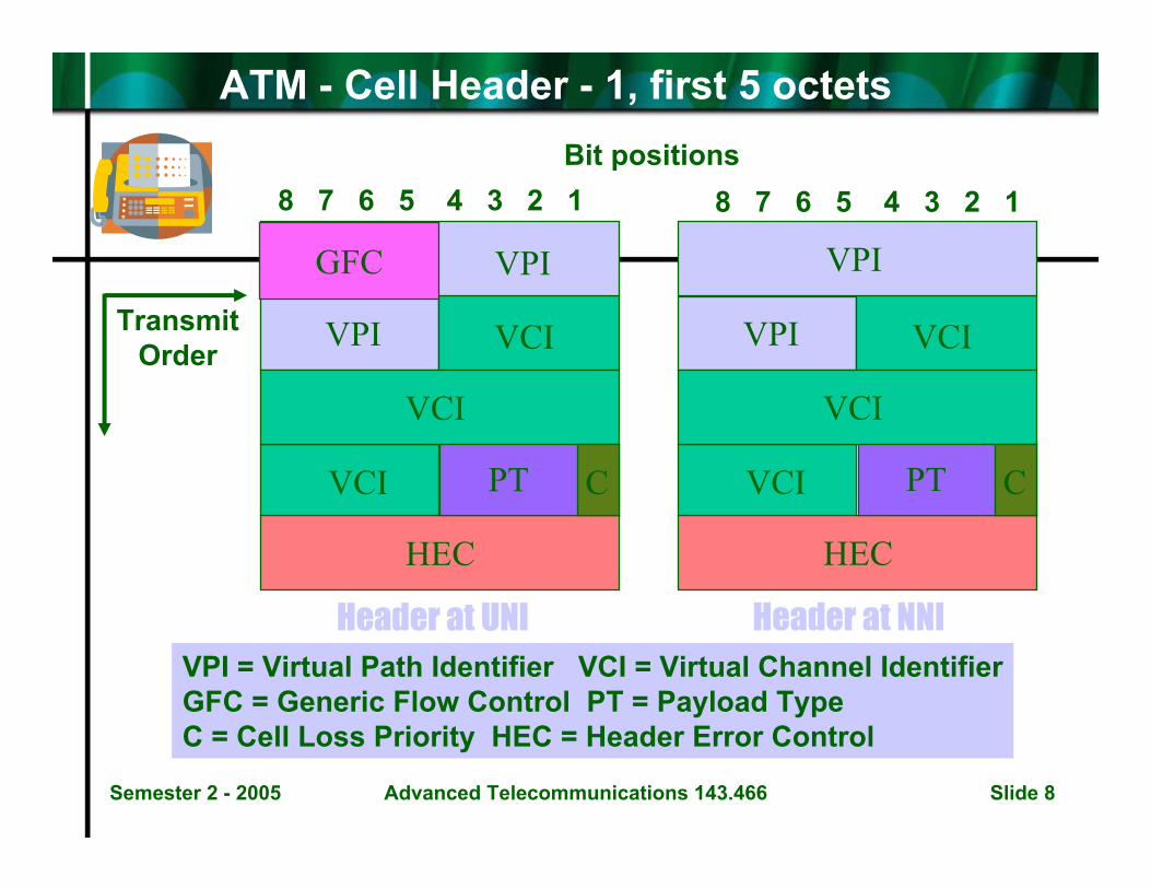
ATM - Cell Header - 1, first 5 octets
8 7 6 5 4 3 2 1 8 7 6 5 4 3 2 1
HEC
CPT
VCI
VCI
VCIVPI
GFC VPI
HEC
CPT
VCI
VCI
VCIVPI
VPI
Header at UNI Header at NNI
TransmitOrder
VPI = Virtual Path Identifier VCI = Virtual Channel IdentifierGFC = Generic Flow Control PT = Payload Type C = Cell Loss Priority HEC = Header Error Control
Bit positions
Semester 2 - 2005 Advanced Telecommunications 143.466 Slide 9
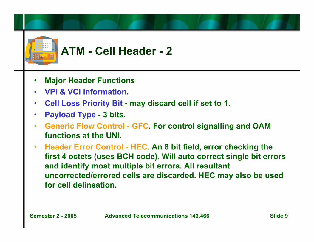
ATM - Cell Header - 2
• Major Header Functions• VPI & VCI information.• Cell Loss Priority Bit - may discard cell if set to 1.• Payload Type - 3 bits.• Generic Flow Control - GFC. For control signalling and OAM
functions at the UNI.• Header Error Control - HEC. An 8 bit field, error checking the
first 4 octets (uses BCH code). Will auto correct single bit errors and identify most multiple bit errors. All resultant uncorrected/errored cells are discarded. HEC may also be used for cell delineation.
Semester 2 - 2005 Advanced Telecommunications 143.466 Slide 10
ATM - Physical layer - 1
Physical Layer - Examples of Transmission Convergence (TC) functions.
• Cell Rate Decoupling
• Header Error Control - HEC
• Cell Delineation
Semester 2 - 2005 Advanced Telecommunications 143.466 Slide 11
ATM - Physical Layer - 2
Transmission Convergence - Cell Rate Decoupling
• If no information is passed down from the ATM layer, the TC sub-layer in the transmitter generates Idle Cells to maintain the specified data rate.
• Some systems are Cell-based with no framing (eg. LAN’s), others are Frame-based, eg. STM-1 frames in SDH. In the former case the user rate is 149.760 Mbps. In the latter case the rate is the well known 155.520 Mbps. ie. 149.760 = 155.520 * (26 : 27).
• In a practical case this means inserting a PLOAM cell after each26 cells. See ATM LAN networks.
Semester 2 - 2005 Advanced Telecommunications 143.466 Slide 12
Physical Layer - 3
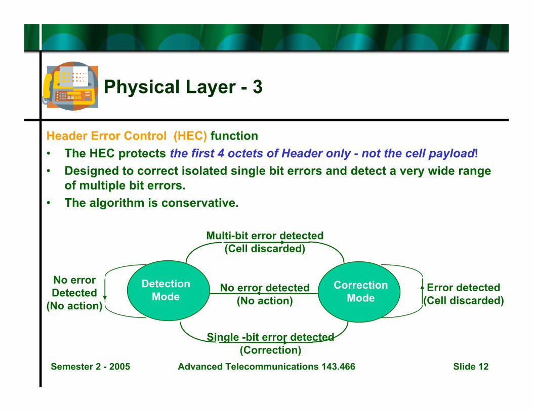
Header Error Control (HEC) function• The HEC protects the first 4 octets of Header only - not the cell payload!• Designed to correct isolated single bit errors and detect a very wide range
of multiple bit errors.• The algorithm is conservative.
Single -bit error detected(Correction)
Error detected(Cell discarded)
DetectionMode
CorrectionMode
Multi-bit error detected(Cell discarded)
No error detected(No action)
No errorDetected
(No action)
Semester 2 - 2005 Advanced Telecommunications 143.466 Slide 13
Physical Layer - 4
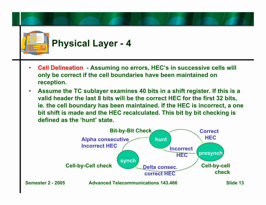
• Cell Delineation - Assuming no errors, HEC’s in successive cells will only be correct if the cell boundaries have been maintained on reception.
• Assume the TC sublayer examines 40 bits in a shift register. If this is a valid header the last 8 bits will be the correct HEC for the first 32 bits, ie. the cell boundary has been maintained. If the HEC is incorrect, a one bit shift is made and the HEC recalculated. This bit by bit checking is defined as the ‘hunt’ state.
presynch
hunt
synch
Correct HEC
Cell-by-cellcheck
Incorrect HEC
Alpha consecutive Incorrect HEC
Delta consec.correct HEC
Cell-by-Cell check
Bit-by-Bit Check
Semester 2 - 2005 Advanced Telecommunications 143.466 Slide 14
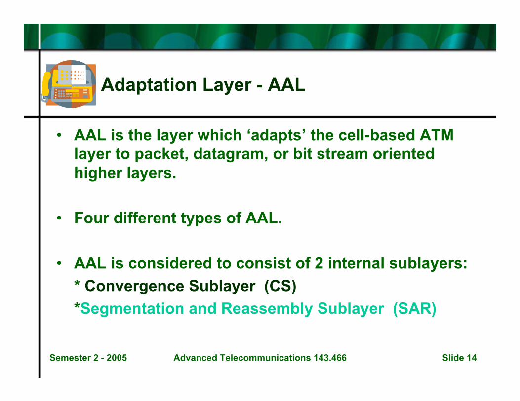
Adaptation Layer - AAL
• AAL is the layer which ‘adapts’ the cell-based ATM layer to packet, datagram, or bit stream oriented higher layers.
• Four different types of AAL.
• AAL is considered to consist of 2 internal sublayers:* Convergence Sublayer (CS)*Segmentation and Reassembly Sublayer (SAR)

Semester 2 - 2005 Advanced Telecommunications 143.466 Slide 15
Adaptation Layer - 2
Service Classification / AAL Types
ServiceParametersTimingCompensation
Bit Rate
ConnectionMode
Example
AAL Type
Class A Class B Class C Class D
Required Not Required
Constant Variable
Connection-Oriented (CO)
Connection-Less (CL)
circuitemulation
variablebit ratevideo
CO datatransfer
CL datatransfer
Type 1 Type 2 Type3Type 5
Type 4
Semester 2 - 2005 Advanced Telecommunications 143.466 Slide 16
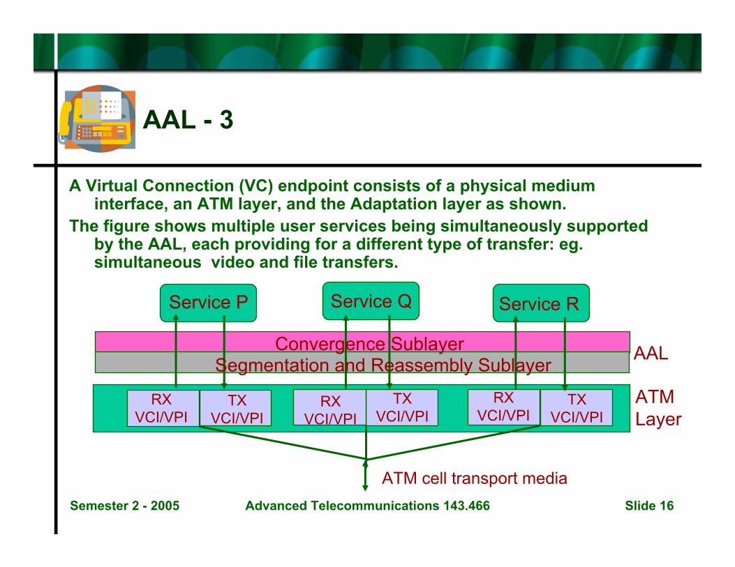
AAL - 3
A Virtual Connection (VC) endpoint consists of a physical mediuminterface, an ATM layer, and the Adaptation layer as shown.
The figure shows multiple user services being simultaneously supported by the AAL, each providing for a different type of transfer: eg.simultaneous video and file transfers.
RXVCI/VPI
RXVCI/VPI
TXVCI/VPI
TXVCI/VPI
RXVCI/VPI
TXVCI/VPI
Convergence SublayerSegmentation and Reassembly Sublayer
Service RService QService P
ATM cell transport media
AAL
ATMLayer
Semester 2 - 2005 Advanced Telecommunications 143.466 Slide 17
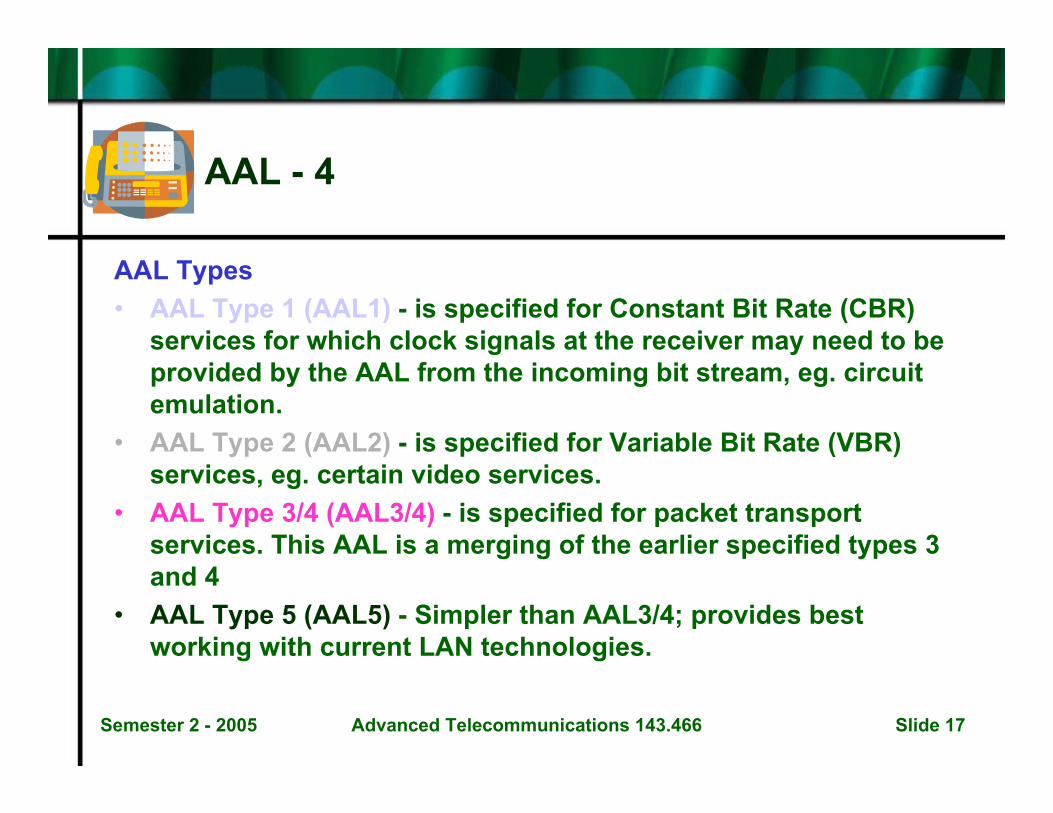
AAL - 4
AAL Types• AAL Type 1 (AAL1) - is specified for Constant Bit Rate (CBR)
services for which clock signals at the receiver may need to be provided by the AAL from the incoming bit stream, eg. circuit emulation.
• AAL Type 2 (AAL2) - is specified for Variable Bit Rate (VBR) services, eg. certain video services.
• AAL Type 3/4 (AAL3/4) - is specified for packet transport services. This AAL is a merging of the earlier specified types 3and 4
• AAL Type 5 (AAL5) - Simpler than AAL3/4; provides best working with current LAN technologies.
Semester 2 - 2005 Advanced Telecommunications 143.466 Slide 18
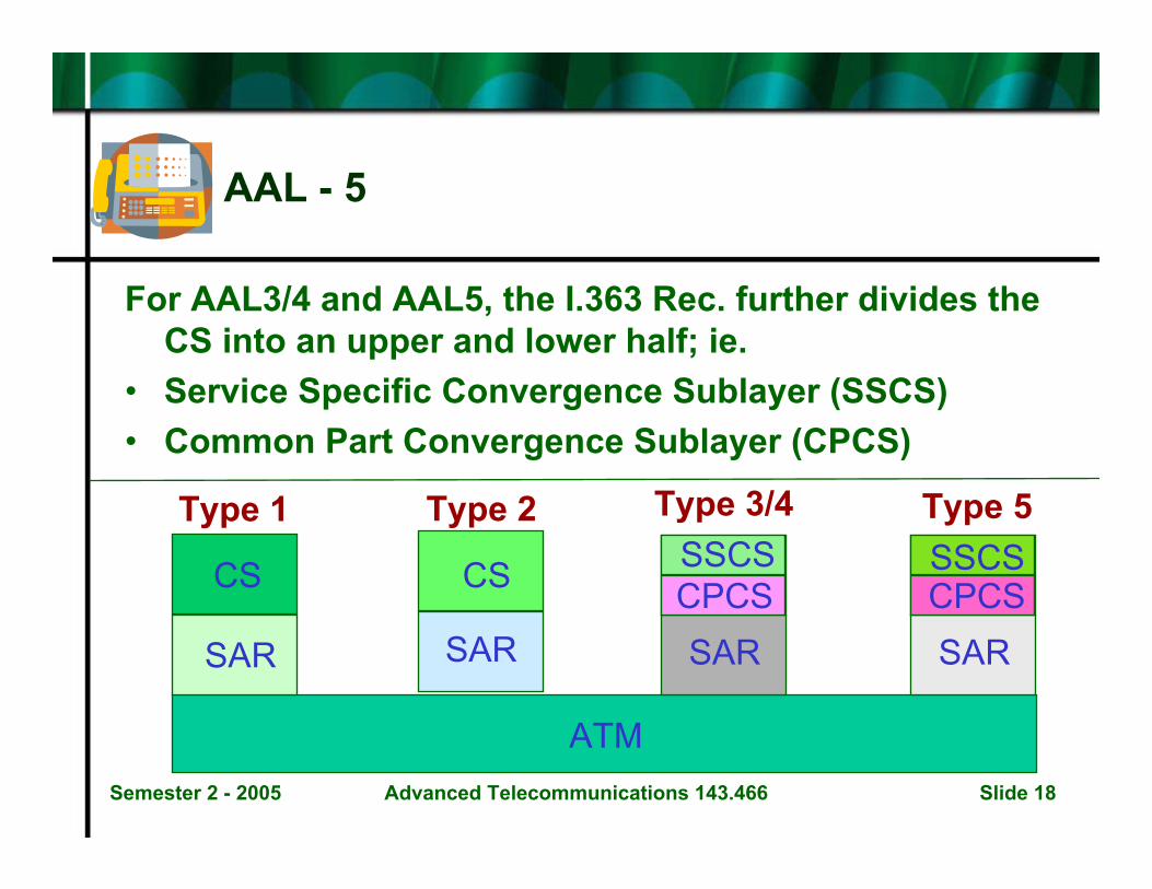
AAL - 5
For AAL3/4 and AAL5, the I.363 Rec. further divides the CS into an upper and lower half; ie.
• Service Specific Convergence Sublayer (SSCS)• Common Part Convergence Sublayer (CPCS)
SSCSSSCSCPCSCPCSCS CS
SAR SAR SAR SAR
ATM
Type 1 Type 2 Type 3/4 Type 5
Semester 2 - 2005 Advanced Telecommunications 143.466 Slide 19
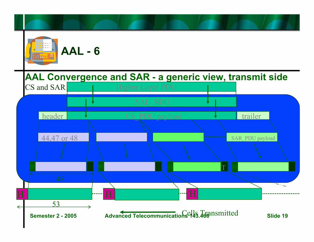
AAL - 6
AAL Convergence and SAR - a generic view, transmit side
HHH
Higher Layer PDU
AAL_SDU
header trailerCS_PDU payload
SAR_PDU payload44,47 or 48
48
53
H T
Cells Transmitted
CS and SAR

Semester 2 - 2005 Advanced Telecommunications 143.466 Slide 20
The Type 1 AAL - 1
• Transfer of Constant Bit Rate Services• Transfer of Timing Information• Indication of Lost/Errored Information• Functions:
– Segmentation and reassembly of user information– Handling of cell delay variation– Handling of lost & miss-inserted cells– Source clock recovery at receiver– Monitoring and handling of certain bit errors
Semester 2 - 2005 Advanced Telecommunications 143.466 Slide 21
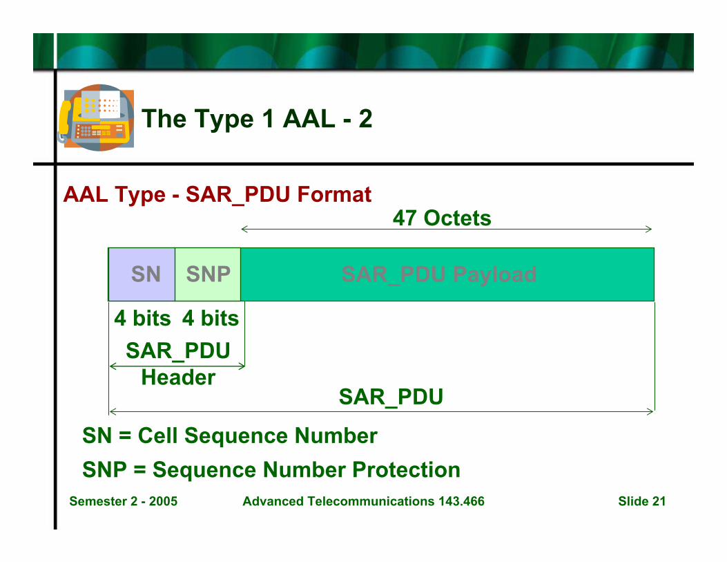
The Type 1 AAL - 2
AAL Type - SAR_PDU Format
4 bits 4 bits
47 Octets
SN SNP SAR_PDU Payload
SAR_PDUHeader
SAR_PDU
SN = Cell Sequence NumberSNP = Sequence Number Protection
Semester 2 - 2005 Advanced Telecommunications 143.466 Slide 22
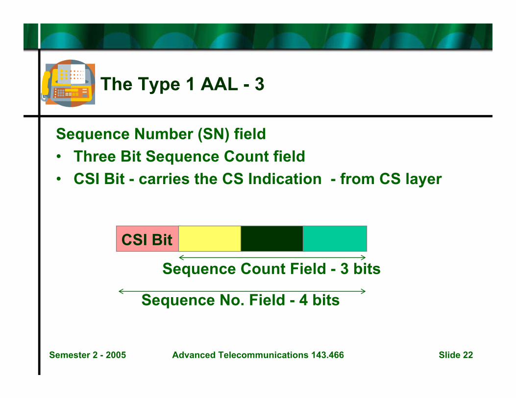
The Type 1 AAL - 3
Sequence Number (SN) field• Three Bit Sequence Count field• CSI Bit - carries the CS Indication - from CS layer
CSI Bit
Sequence Count Field - 3 bits
Sequence No. Field - 4 bits
Semester 2 - 2005 Advanced Telecommunications 143.466 Slide 23
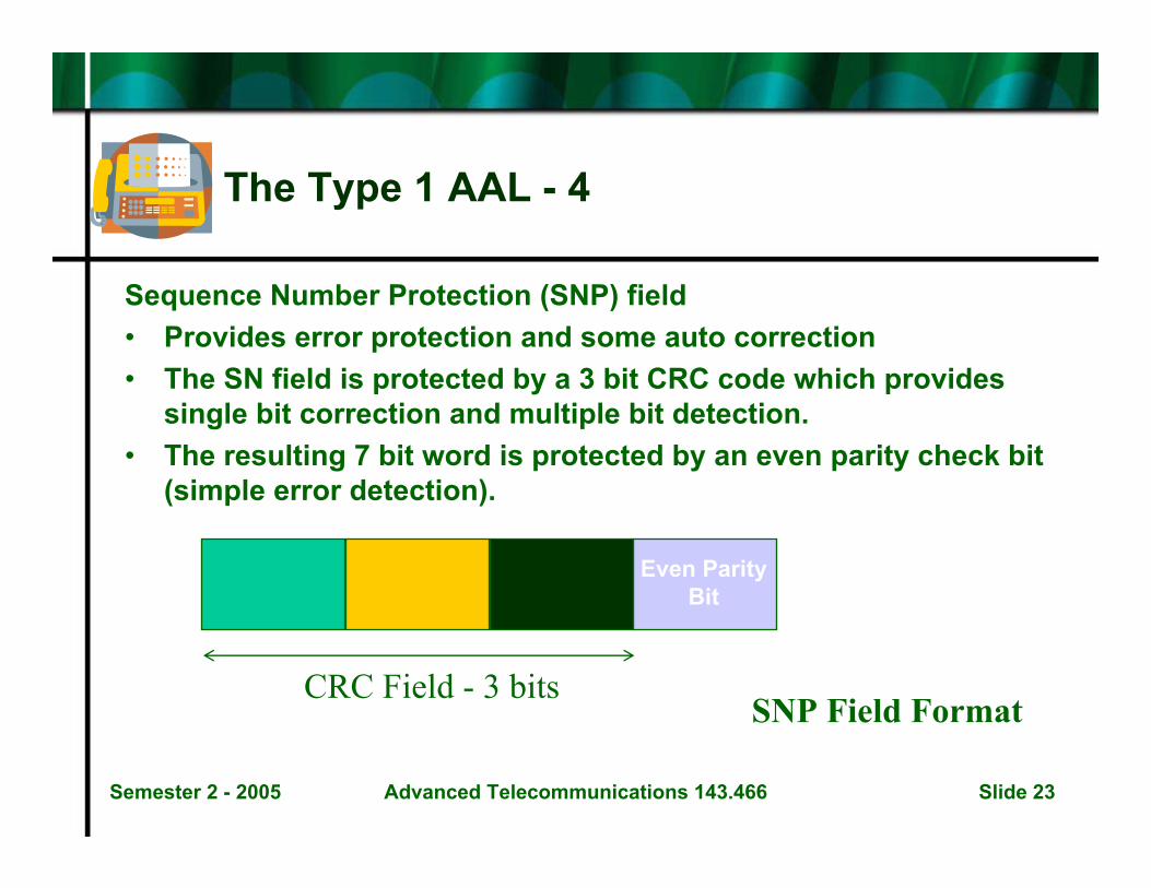
The Type 1 AAL - 4
Sequence Number Protection (SNP) field• Provides error protection and some auto correction• The SN field is protected by a 3 bit CRC code which provides
single bit correction and multiple bit detection.• The resulting 7 bit word is protected by an even parity check bit
(simple error detection).
Even ParityBit
CRC Field - 3 bitsSNP Field Format
Semester 2 - 2005 Advanced Telecommunications 143.466 Slide 24
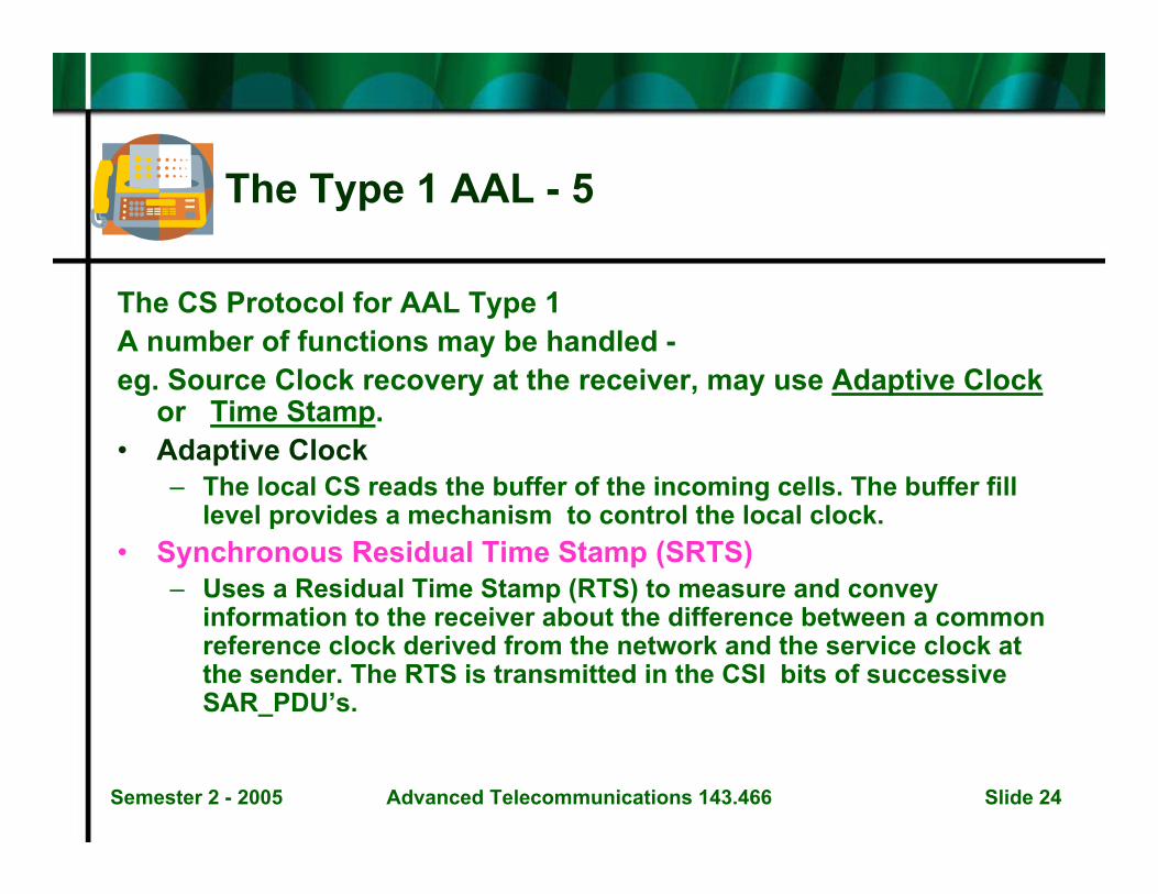
The Type 1 AAL - 5
The CS Protocol for AAL Type 1A number of functions may be handled -eg. Source Clock recovery at the receiver, may use Adaptive Clock
or Time Stamp.• Adaptive Clock
– The local CS reads the buffer of the incoming cells. The buffer fill level provides a mechanism to control the local clock.
• Synchronous Residual Time Stamp (SRTS)– Uses a Residual Time Stamp (RTS) to measure and convey
information to the receiver about the difference between a common reference clock derived from the network and the service clock at the sender. The RTS is transmitted in the CSI bits of successive SAR_PDU’s.
Semester 2 - 2005 Advanced Telecommunications 143.466 Slide 25
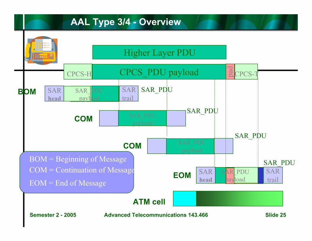
AAL Type 3/4 - Overview
CPCS_PDU payload
SARhead
SARtrail
Higher Layer PDU
pad
CPCS-H CPCS-T
SARhead
SARtrail
SAR_PDUpayload
SAR_PDUpayload
SAR_PDUpayload
SAR_PDUpayload
SAR_PDU
SAR_PDU
SAR_PDU
SAR_PDU
EOM
ATM cell
BOM
COM
COMBOM = Beginning of MessageCOM = Continuation of Message
EOM = End of Message
Semester 2 - 2005 Advanced Telecommunications 143.466 Slide 26
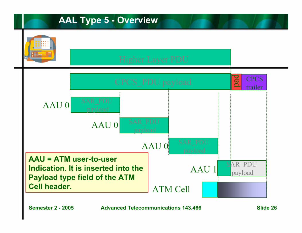
AAL Type 5 - Overview
SAR_PDUpayload
SAR_PDUpayload
Higher Layer PDU
CPCS_PDU payload
SAR_PDUpayload
SAR_PDUpayload
CPCStrailerpa
d
ATM Cell
AAU 0
AAU 0
AAU 0
AAU 1AAU = ATM user-to-userIndication. It is inserted into the Payload type field of the ATMCell header.
Semester 2 - 2005 Advanced Telecommunications 143.466 Slide 27
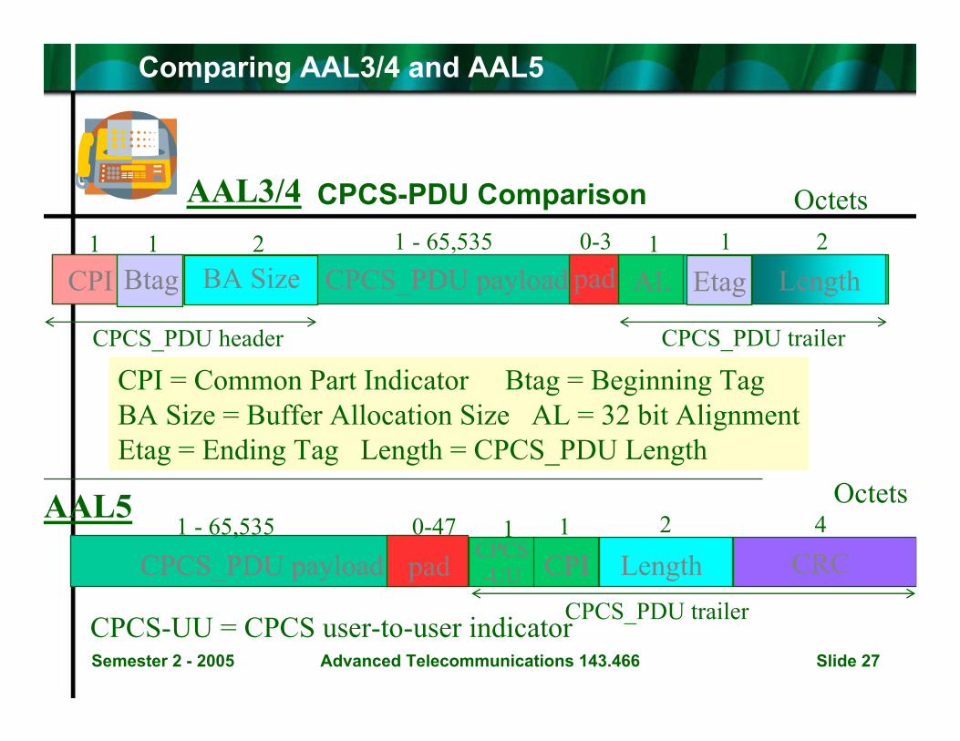
Comparing AAL3/4 and AAL5
CPCS-PDU Comparison
CPI = Common Part Indicator Btag = Beginning TagBA Size = Buffer Allocation Size AL = 32 bit AlignmentEtag = Ending Tag Length = CPCS_PDU Length
AAL3/4 Octets
AAL5
CPCS_PDU payload CPCS-UU CPI Length CRCpad
1 - 65,535 0-47 1 1 2 4Octets
CPCS_PDU trailer
EtagCPI Btag BA Size CPCS_PDU payload AL Lengthpad1 1 2 0-3 1 1 21 - 65,535
CPCS_PDU header CPCS_PDU trailer
CPCS-UU = CPCS user-to-user indicator

Semester 2 - 2005 Advanced Telecommunications 143.466 Slide 28
Comparing AAL3/4 and AAL5
A comparison at the SAR sublayer is made. (The AAL type1 SAR_PDU is also drawn for reference)
SNPSN SAR_PDU payload
SAR_PDU payload
47 octets1 octet
SAR_PDU payloadSNST MID LI CRC
2 octets 44 octets 2 octets
48 octets
Type 1
Type 3/4
Type 5
SN = Sequence No. ST = Segment Type MID = Multiplexing Ident.LI = Length Indicate CRC = Cyclic Redundancy Check

Semester 2 - 2005 Advanced Telecommunications 143.466 Slide 29
AAL5 - A final note
A single bit in the PTI field of the cell header is termed the ATM-layer-user-to-ATM-layer-user parameter - AAU.
• AAU = 1 to mark the last SAR_PDU of a CPCS_PDU(or the only SAR_PDU of a small CPCS_PDU).
• AAU = 0 for cells carrying the beginning and continuation SAR_PDU’s ( for CPCS_PDU’s spanning more than one cell. See Slide titled
• “AAL Type 5 - Overview”
Cell Header SAR_PDU 48 octets
One Bit AAU in PTI
Semester 2 - 2005 Advanced Telecommunications 143.466 Slide 30
Comparative Reviews
• Now that we have provided an overview of ATM and other forms of packet switching, we shall now revisit these earlier technologies and provide some comparative reviews of– ATM versus Frame Relay– ATM versus LAN technologies– ATM versus IP
Semester 2 - 2005 Advanced Telecommunications 143.466 Slide 31
ATM Versus Frame Relay - 1
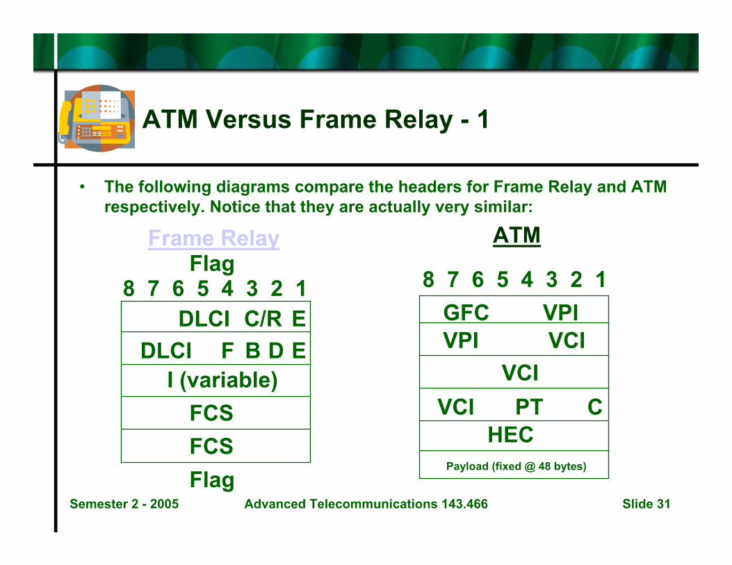
• The following diagrams compare the headers for Frame Relay and ATM respectively. Notice that they are actually very similar:
Frame Relay ATM
8 7 6 5 4 3 2 1 8 7 6 5 4 3 2 1
DLCI C/R EB D
I (variable)FCS
Flag
DLCI F E
Flag
FCS
GFC VPIVPI VCI
VCIVCI PT C
HECPayload (fixed @ 48 bytes)

Semester 2 - 2005 Advanced Telecommunications 143.466 Slide 32
ATM Versus Frame Relay - 2
• Key to acronyms:– B = Backward explicit congestion notification bit (BECN)– C = Cell loss priority bit (CLP)– C/R = Command/response bit– D = Discard eligibility bit (DE)– DLCI = data link connection identifier– E = Address extension bit– F = Forward explicit congestion notification bit (FECN)– FCS = Frame check sequence field– GFC = Generic Flow Control field– HEC = Header Error Control field– I = Information field (user traffic)– PT = Payload Type identifier– VCI = Virtual Channel Identifier– VPI = Virtual Path Identifier
Semester 2 - 2005 Advanced Telecommunications 143.466 Slide 33
ATM Versus Frame Relay - 3
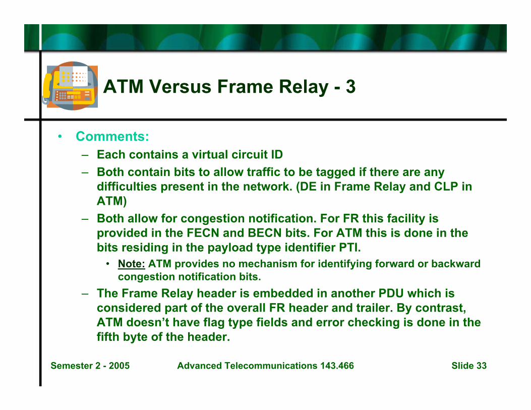
• Comments:– Each contains a virtual circuit ID– Both contain bits to allow traffic to be tagged if there are any
difficulties present in the network. (DE in Frame Relay and CLP in ATM)
– Both allow for congestion notification. For FR this facility is provided in the FECN and BECN bits. For ATM this is done in the bits residing in the payload type identifier PTI.
• Note: ATM provides no mechanism for identifying forward or backward congestion notification bits.
– The Frame Relay header is embedded in another PDU which is considered part of the overall FR header and trailer. By contrast, ATM doesn’t have flag type fields and error checking is done in the fifth byte of the header.

Semester 2 - 2005 Advanced Telecommunications 143.466 Slide 34
ATM Versus Frame Relay - 4
Attribute Frame Relay ATM
Application support Asynchronous data –not designed for voice.
Asynchronous,synchronous voice, video,data.
Connection mode Connection-oriented Connection-orientedCongestionmanagement
Yes, congestionnotification, traffictagging and possibletraffic discard.
Yes, congestionnotification, traffictagging and possibletraffic discard.
PVC Yes YesSVC (connection ondemand)
Yes Yes
Congestion notificationtechnique
The FECN and BECNbits
The CN bits in the PTIfield
LAN or WANtechnology
WAN based Either
PDU size Variable (PDU iscalled a frame)
Fixed at 53 bytes. PDU iscalled a “cell”.
ACK/NAKretransmissions
No Only for signalling trafficon SVCs

Semester 2 - 2005 Advanced Telecommunications 143.466 Slide 35
ATM Versus LAN Technologies - 1
Attribute Ethernet IEEE 802.3 ATM
Application support Asynchronous data –with some voice, butnot designed for voice.
Asynchronous data –with some voice, but notdesigned for voice.
Asynchronous,synchronous voice, video,data.
Connection mode Connectionless Connectionless Connection-orientedCongestionmanagement
Collision detection Collision detection Yes, congestionnotification, traffictagging and possibletraffic discard.
Method of identifyingtraffic
48-bit MAC address 48-bit MAC address Virtual circuit ID: TheVPI/VCI and an ATMaddress
Congestion notificationtechnique
None None The CN bits in the PTIfield
PDU size Variable Variable Fixed at 53 bytes. PDU iscalled a “cell”.
ACK/NAKretransmissions
No No Only for signalling trafficon SVCs
Semester 2 - 2005 Advanced Telecommunications 143.466 Slide 36
ATM Versus IP - 1
• These two technologies use different identifiers and different encapsulation headers.
• ATM is connection oriented• IP is connectionless.

Semester 2 - 2005 Advanced Telecommunications 143.466 Slide 37
ATM Versus IP - 2Attribute IP ATM
Application support Asynchronous data –not designed for voice.
Asynchronous,synchronous voice, video,data.
Connection mode Connectionless Connection-orientedCongestionmanagement
None Yes, congestionnotification, traffictagging and possibletraffic discard.
Method of identifyingtraffic
32-bit IP address Virtual circuit ID: TheVPI/VCI and an ATMaddress
Congestion notificationtechnique
None The CN bits in the PTIfield
PDU size Variable Fixed at 53 bytes. PDU iscalled a “cell”.
ACK/NAKretransmissions
No Only for signalling trafficon SVCs