Embed Size (px)
Citation preview

1
ATOConnection andDebuggingManualforAll-digitalAC ServoDriver

2
Table of ContentsImportant Safety Information.................................................................................................................................1
Chapter I Installation............................................................................................................................................ 3
Outline Dimensions of the Servo Driver........................................................................................................... 3
Installation Dimensions for the Servo Driver...................................................................................................... 4
Installation Site.................................................................................................................................................... 5
Direction and Space of Installation.....................................................................................................................6
Chapter II Overview of Functions.......................................................................................................................9
Basic Functions of MG -1000 Series of Servos............................................................................................ 9
Type Selection of the Servo Driver..................................................................................................................10
Chapter III Wiring..............................................................................................................................................13
Noti ces.................................................................................................................................................................13
Wiring Requirements..........................................................................................................................................13
Wiring Methods................................................................................................................................................. 13
Typical Wiring...................................................................................................................................................14
Position Control (pulse type).........................................................................................................................14
Speed Control (analog value)........................................................................................................................ 15
Torque Control (analog value)....................................................................................................................... 16
Wiring Diagram for Wire Saving Motor Encoder................................................................................................. 17
Wiring Diagram for the Band-type Brake of the Servo Motor.....................................................................18
Chapter IV Interfaces..........................................................................................................................................19
Definitions of Servo Control Power Supply and Heavy Current Terminal.................................................19
Definitions of CN1 Interface and Control Signal Input/output..................................................................20
Definitions of CN2 interface and Encoder Input Signal.............................................................................. 25
Principle of the Input Interface for Switching Value.............................................................................................. 26
4.5 Principle of the Output Interface for Switching Value...............................................…............................. 26
4.6 Principle of the Input Interface for Pulse Value...........................................................................................27
4.6.1 Input Mode of Pulse.................................................................................................................................28
Principe of the input interface of Analog Value............................................................................................28
Principe of Encoder Interface..........................................................................................................................30
CN1 Output Interface for Encoder Signal (from the driver to the upper computer)..............................................30
CN2 Input Interface for Encoder Signal (from the servo motor to the driver)........................................................31
CN1 Output Interface for Z signal of the Encoder (from driver output to zeroing by the upper computer) ...31
Chapter V Display and Operation...................................................................................................................... 33
Operation Panel.................................................................................................................................................33
Components of Parameter Structure.................................................................................................................. 34
Status Monitoring Mode (DP - -)................................................................................................................. 35
Parameter Modification Mode (PA--)............................................................................................................ 38
Parameter Management Mode (EE--).............................................................................................................39
JOG Operational Mode (Jr- -)....................................................................................................................40
Speed Trial Run Mode (Sr- -).................................................................................................................... 40
Automatic Zeroing Mode of Analog Value (AU- -)......................................................................................41
Automatic Zeroing Mode of Encoder (CO- -)............................................................................................. 42Open Loop Operation Mode (OL- -)............................................................................................................ 42
3
Chapter VI Parameters...................................................................................................................................... 43
List of Parameters [PA Mode]...................................................................................................................... 43
Detailed Explanation of Parameters....................................................................................................................45
Chapter VII Failures and Diagnosis................................................................................................................... 57
List of Alarms...................................................................................................................................................57
Troubleshooting...................................................................................................................................................................... 58
Chapter VIII Debugging and Application.........................................................................................................61
Notices to Quick Debugging..........................................................................................................................61
Position Control (Quick adjustment of parameters after power on)....................................................................... 64
Speed Control (Quick adjustment of parameters after power on).....................................................................66
Torque Control (Quick adjustment of parameters after power on)................................................................ 67
Dynamic Electronic Application.................................................................................................................... 69
Debugging of Typical Problems.......................................................................................................................69
Chapt er IX Servo Mot or................................................................................................................................71

4
ImportantSafety Information
I. Personnel Safety●This product is a high-voltage heavy current product. Make sure that personal are within the
safety area of moving mechanisms.
● Improper operation may cause accidents such as electric arc burn or electric shock, etc.
● It is not allowed to operate, wire and electrify the product without following this manual.
II. ite Safety● This product is a high-voltage heavy current product. It is not allowed to electrify and use the
product where there are combustible or corrosive gases; otherwise fire and explosion may be caused.
● It is not allowed to electrify and use the product where combustible or corrosive articles drop;
otherwise fire and explosion may be caused.
● It is not allowed to use the product in the places with high humidity, moisture and metal powder;
otherwise dangerous accidents such as electric shock, etc. may be caused.
III. roduct and Equipment Safety● This product is a high-voltage heavy current product. Incorrect connection may lead to damage to the
product.
● PE terminal must be connected to a ground wire and make sure that the ground wire is reliably
grounded.
● AC 220V power supply is suitable for this product. Do not connect an AC380V one to the servo
driver.
● The U, V and W of the product should be connected with the motor. They are outputs. Do not connect
them with input power supply.
● Do not connect the three-phase outputs U, V and W of the product in an incorrect sequence; because
incorrect connection may lead to motor racing, damage to equipment, and overcurrent damage to the
product.
●Tighten all terminals. The materials of all matching wires should be strictly selected according
to power.
● Power distribution and touching of the terminals are not allowed when the driver is electrified.
● Do not touch the terminals within five (5) minutes after power down.
● It is not allowed to touch the motor and cables when the motor is in operation in order to avoid
accidental injuries such as scalding and wrench, etc.

5
Remarks
It is hereby declared that :● 2A/3A/5A/ shown in the manual or nameplate are the abbreviations for 20A/30A/50A.

6
Chapter I Installation
1.1 Outline Dimensions of the Servo Driver
Figure 1.1 Outline Dimensional Drawings
for the Servo Driver of 30A/30A

7
1.11 Outline Dimensions of the Servo Driver
Figure 1.2 Outline Dimensional Drawings
for the Servo Driver of 50A/75A

8
1.2 Installation Dimensions for the Servo Driver
Figure 1.11 Installation Dimensions
for the Servo Driver of 30A/30A

9
1.21 Installation Dimensions for the Servo Driver
Figure 1.21 Installation Dimensions
for the Servo Driver of 50A/75A

10
Installation Site
I. To make sure that the servo driver works normally, it is necessary to ensure that the temperature
around the driver is below 50°C and that the relative humidity is below 90%. The long-term safe
working temperature should be below 40°C.
II. The servo driver is subject to failures when used in a severe environment with corrosive gases,
high humidity, metal powder, water or processing liquids. Therefore, the working environment
should be fully taken into consideration during the use and installation.
III. The vibration acceleration of the equipment which is directly or indirectly connected with the
servo driver should be below 0.5G (4.9m/S2) or less in order to ensure long-term stable operation
of the servo driver.
IV. The servo driver could be disturbed when it is disturbing other facilities at the same time, so
attention must be paid to the wiring of heavy current and weak current during the installation of a
electric cabinet or complete equipment. The servo driver is unable to work normally and also
probably led to produce malfunction due to strong external disturbing signals or the serious effect
on the power cord of the servo driver and control signal. At the same time control equipment such
as a upper computer, etc. also cannot work stably under the disturbance of the servo driver due to
poor wiring. Pay attention to install a sound magnetic ring, a wave filter and an isolation
transformer, etc. at the source of the disturbance and in the places which are disturbed. Pay special
attention that the wire of control signal is subject to disturbance; therefore reasonable wiring and
shielding measures should be taken.

11
Direction and Space of Installation
I. Pay attention to the direction of installation (See Figure 1.3).
II. Pay attention to the spacing of installation (See Figure 1.3).
III. Four (4) M5 bolts can fix the servo driver with a spring washer added.
IV. The servo must be installed in a relatively closed space, with ventilation maintained in the
electric cabinet and a filter screen installed at the vent to prevent the entry of dust. Clear the filter
screen periodically to prevent air flow from being blocked.
Figure 1.3 Direction of Installation
伺服驱动器 Servo Driver向上通风Upward ventilation 150mm以上 above 150mm

12
Chapter II Overview of Functions
Basic Funct ions of MG -1000 Series of Servos
Type MG -1000 (20A/30A/50A/75A)Control power supply and main
circuit power supply
Single phase or three phase AC 220V
Voltage fluctuation:-15-+10%, 50/60Hz
Environment
Temperature Working temperature: 0-550C
Storage temperature: -400C-800C
Humidity No more than 90%( without condensation)
Air index No dust (conductive media such as metal powder, etc.) in the electric
cabinet
Control mode
1. Position control 2. Speed control
3. Torque control 4. JOG operation
5. Four Internal speed control 6. Internal position control
7. Internal torque control 8. Position & speed control
9. Speed & torque control
External I/O
1. Servo enable 2. Reset
3. Position deviation reset
4. Pulse, CCW, and CW disabled.
5. Position switching
6. Speed selection
7. Zero speed clamping
8. The second reset
9. Extended functions (options) such as orientation and permissible stop,
etc.
Encoder feedback 10000p/r(standard); frequency division permissible (options)
Communicationmode 1. RS232(closed)
2. RS485 (closed)
Load inertia 5 times smaller than that of the motor
Monitoring function Speed, current position, command pulse accumulation, position deviation,
motor current, operation status, input and output terminals, and Z pulse
signal, etc.
Protection function Overvoltage, overcurrent, overspeed, and incorrect feedback, etc.
Alarm function Alarms (LED flashing; red lamp on) are often given off when the servo
operates abnormally.
Gain adjustment Gain adjustment can be carried out to match motor performance when the
motor operates or stops.
Adaptive motor See Tables 2.21, 2.22 and 2.23.

13
TypeSelection of the Servo Driver
MG-1000 B 30 L(1) (2) (3) (4) (5)(1) Series: Dealour’s common types of servo drivers are adaptable to multiple
specifications of servo motors and industries with rich forms of database.
(2) Feedback elements: 1000 2500C/T incremental type and wiring saving type
encoders, S sine and cosine (217bi/218bit(131072/262144)), M multi-loop bus type
(217/216bit(131072/65536)), and B single-loop bus type (220bit(1048576))
(3) Control mode: B position control, C all-function position/speed/torque control,
and T special type PLC function with a touch screen
(4) IPM module specification: 15A and 20A are called 2A for short; 30A, 3A; and
50A, 5A and 75A.
(5) Main circuit voltage: L single phase or three phase 220V; H three phase 380V;
default 220Vwhen this voltage is omitted.
TypeCode Applicable Driver ApplicableMotorPower(kW)
RatedCurrent(A)
Rated Toque(Nm)
27
MG-1000/30A
80ST-M01330 0.4 2.6 1.328 80ST-M02430 0.75 4.2 2.429 80ST-M03330 1.0 4.2 3.334 110ST-M02030LBF 0.6 4 235 110ST-M04030LBF 1.2 5 436 110ST-M05030LBF 1.5 6 537 110ST-M06020LBF 1.2 6 638 110ST-M06030LBF 1.8 8 644 130ST-M04025LBF 1 4 445 130ST-M05025LBF 1.3 5 546 130ST-M06025LBF 1.5 6 647 130ST-M07720LBF 1.6 6 7.748 130ST-M07725LBF 2.0 7.5 7.7
130ST-M07730LBF 2.4 9 7.749 130ST-M10015LBF 1.5 6 1050 130ST-M10025LBF 2.6 10 1051 130ST-M15015LBF 2.3 9.5 1552 130ST-M12020LBF 2.4 10 12
Table 2.21 MG -1000/30A

14
TypeCode Applicable Driver ApplicableMotorPower(kW)
RatedCurrent(A)
Rated Toque(Nm)
0
MG-1000/50A
130ST-M07720LBF 1.6 6 7.71 130ST-M07725LBF 2.0 7.5 7.7
130ST-M07730LBF 2.4 9 7.72 130ST-M10015LBF 1.5 6 103 130ST-M10025LBF 2.6 10 104 130ST-M15015LBF 2.3 9.5 155 130ST-M15025LBF 3.9 17 156 150ST-M12030LBF 3.6 16.5 127 150ST-M15025LBF 3.8 16.5 158 150ST-M18020LBF 3.6 16.5 189 150ST-M23020LBF 4.7 20.5 2310 150ST-M27020LBF 5.5 20.5 2711 150ST-M12020LBF 2.4 10 1212 180ST-M17215LBF 2.7 10.5 1713 180ST-M19015LBF 3 12 1914 180ST-M21520LBF 4.5 16 2115 180ST-M27010LBF 2.9 12 2716 180ST-M27015LBF 4.3 16 2717 180ST-M35010LBF 3.7 16 3518 180ST-M35015LBF 5.5 24 3519 180ST-M48015LBF 7.5 32 48
Table 2.22 MG-1000/50A

15
TypeCode Applicable Driver ApplicableMotorPower(kW)
RatedCurrent(A)
Rated Toque(Nm)
0
MG-1000/75A
130ST-M07720LBF 1.6 6 7.71 130ST-M07725LBF 2.0 7.5 7.7
130ST-M07730LBF 2.4 9 7.72 130ST-M10015LBF 1.5 6 103 130ST-M10025LBF 2.6 10 104 130ST-M15015LBF 2.3 9.5 155 130ST-M15025LBF 3.9 17 156 150ST-M12030LBF 3.6 16.5 127 150ST-M15025LBF 3.8 16.5 158 150ST-M18020LBF 3.6 16.5 189 150ST-M23020LBF 4.7 20.5 2310 150ST-M27020LBF 5.5 20.5 2711 150ST-M12020LBF 2.4 10 1212 180ST-M17215LBF 2.7 10.5 1713 180ST-M19015LBF 3 12 1914 180ST-M21520LBF 4.5 16 2115 180ST-M27010LBF 2.9 12 2716 180ST-M27015LBF 4.3 16 2717 180ST-M35010LBF 3.7 16 3518 180ST-M35015LBF 5.5 24 3519 180ST-M48015LBF 7.5 32 48
Table 2.23 MG-1000/75A

16
Chapter III Wiring
Notices
● The servo driver is a high voltage e heavy current product. Improper connection may cause
damage to personnel and equipment.
● PE terminal must be connected to a ground wire and make sure that the ground wire is reliably
grounded.
●AC 220V power supply is suitable for this product. Do not connect an AC380V one to the servo
driver.
● The U, V and W of the product should be connected with the motor. They are outputs. Do not
connect themwith input power supply.
● Do not connect the three-phase outputs U, V and W of the product in an incorrect sequence;
because incorrect connection may lead to motor racing, damage to equipment, and overcurrent
burnout to the product.
● Tighten all terminals. The materials of all matching wires should be strictly selected according
to power.
●Power distribution and touching of the terminals are not allowed when the driver is electrified.
● Do not touch the terminals within five (5) minutes after power down.
● It is not allowed to touch the motor and cables when the motor is in operation in order to avoid
accidental injuries such as scalding and wrench, etc.
Wiring Requirements
● A three-phase isolation transformer is preferred for power supply.
● The required diameters of R, S, T and U, V, W, PE wires should be equal to and more than
1.5mm2.
● All power terminals should be cold-pressed ones, firm and reliable.
●CN1 and CN2 are high-density signal plugs that need cables with a shielding layer.
● The wires for connecting PE terminals should be yellow-green ones with a diameter equal to
and more than 2.5mm2.
Wiring Methods
●A three-phase isolation transformer is preferred for power supply.

17
●The required diameters of R, S, T and U, V, W, PE wires should be equal to and more than
1.5mm2.
● All power terminals should be cold-pressed ones, firm and reliable.
●CN1 and CN2 are high-density signal plugs, with both ends of the shielding layer grounded and
connected with the housing.
●The wires for connecting PE terminals should be put through with the equipment housing ground
wire and connected to the earth.

18
Typical Wiring
Position Control (pulse type)
Figure 3.1 Wiring of Position Control
(断路器) (Circuit breaker)
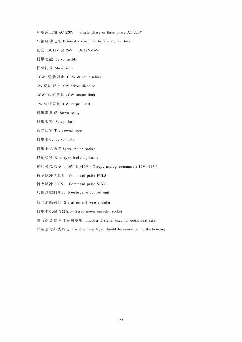
单相或三相 AC 220V Single phase or three phase AC220V

19
外接制动电阻 External connect ion to braking resistor s
直流 DC12V 至 24V DC12V-24V
伺服使能 Servo enable
报警清零 Alarm reset
CCW 驱动禁止 CCW driver disabled
CW 驱动禁止 CW driver disabled
偏差计数清零 Deviation count reset
指令脉冲禁止 Command pulse disabled
伺服准备好 Servo ready
伺服报警 Servo al arm
第二回零 The second reset
伺服电机 Servo motor
伺服电机插座 Servo motor socket
抱闸松紧 Band -type brake tightness
指令脉冲 PULS Command pulse PULS
指令脉冲 SIGN Command pulse SIGN
反馈 到控制单元 Feedback to control unit
信号地编码器 0V signal ground wire encoder 0V
伺服电机编码器插座 Servo motor en coder socket
编码器 Z 信号设备回零用 Encoder Z signal used for equipment reset
屏蔽层与外壳相连 The shielding layer should be connected to the housing.

20
Speed Control (analog value)
Figure 3.1 Wiring of Speed Control
(断路器) (Circuit breaker)
单相或三相 AC 220V Single ph ase or three phase AC 220V

21
外接制动电阻 External connect ion to braking resistors
直流 DC12V 至 24V DC12V-24V
伺服使能 Servo enable
报警清零 Alarm reset
CCW 驱动禁止 CCW driver disabled
CW 驱动禁止 CW driver disabled
零速箝位 /速度选择 1 Zero speed clamping/speed selection 1
速度选择 2 Speed selec tion 2
伺服准备好 Servo ready
伺服 报警 Servo alarm
第二回零 The second reset
伺服电机 Servo motor
伺服电机插座 Servo motor socket
抱闸松紧 Band -type brake tightness
速度模拟指令( -10V 到+10V)Speed analog command (-10V-+10V)
指令脉冲 PULS Command pulse PULS
指令脉冲 SIGN Command pulse SIGN
反 馈到控制单元 Feedback to control unit
信 号地编码器 Signal ground wire encoder
伺服电机编码器插座 Servo motor encoder socket
编码器 Z 信号设备回零用 Encoder Z signal used for equipment reset
屏蔽层与外壳相连 The shielding layer should be connected to the housing .

22
Torque Control (analog value)
Figure 3.1 Wiring of Torque Control
(断路器) (Circuit breaker)
23
单相或三相 AC 220V Single phase or three phase AC 220V
外接制动电阻 External connect ion to braking resistors
直流 DC12V 至 24V DC12V-24V
伺服使能 Servo enable
报警清零 Alarm reset
CCW 驱动禁止 CCW driver disabled
CW 驱动 禁止 CW driver disabled
CCW 转矩限制 CCW torque limit
CW 转矩限制 CW torque limit
伺服准备好 Servo ready
伺服报警 Servo alarm
第二回零 The second reset
伺服电机 Servo motor
伺服电机插座 Servo motor socket
抱闸松紧 Band -type brake tightness
转矩 模拟指令( -10V 到+10V)Torque analog comman d (-10V-+10V )
指令脉冲 PULS Command pulse PULS
指令脉冲 SIGN Command pulse SIGN
反馈到控制单元 Feedback to control unit
信号地编码器 Signal ground wire encoder
伺服电机编码器插座 Servo motor encoder socket
编码器 Z 信号设备回零用 Encoder Z signal used for equipment reset
屏蔽层与外壳相连 The shielding layer should be connected to the housing

24
Wiring Diagram for Wire Saving Motor Encode r
Figure 3.4 Wiring Diagram for Wire Sav ing Motor Encoder
伺服驱动器 Servo driver
伺服电机 Servo motor
伺服电机插座 Servo motor socket
省线式伺服电机编码器 Wire saving servo motor encode r
● A wire saving encode r should be selected for servo motors below 80 series
● A common incremental encoder should be selected for servo motors above 110
series(see Figure 3.2). Recover the automatic recognition of the driver when the
adaptive motor is delivered. It is not necessary to change parameters (see Page 64).
Wiring Diagram for the Band-type Brake of the Servo Motor

25
Figure3.5 Wiring Diagram for Band -type Brake Motor
伺服电机 Servo motor
抱闸线圈 Band-type brake coil
DC12V 到 DC24V 开关量信号电源 Power supply for DC12V-DC24V switching value signal
KA 继电器 KA relay
MG-1000 伺服驱动器MG -1000 servo driver
制动电源 DC12V 到 DC24V DC12V- DC24V braking power supply
Pin No. Pin mark Function Description1 DC+ DC power supply positive pole DC24V +2 DC- DC power supply negative pole 0V3 PE Housing ground wire
Table 3.1 Socket for Servo Motor Band-type Brake
● It is required that the band -type brake braking power supply should be separated from the
upper computer and the DC power supply of the driver to prevent interference.
● The braking power supply for the band-type brake has positive and negative poles, which
should not be connected reversely to prevent short circuit.
● In order to improve braking effect and response, a fly- wheel diode may be added at both ends
of the braking coil(pay attention to the positive and negative poles of the diode).

26
Chapter IV Interfaces
Definitions of Servo Cont rol Power Supply and Heavy Current
TerminalMark SignalName FunctionR Control circuit and main
circuit power supply
(switched in via the isolation
transformer)
R, S and T can be connected to a signal-phase or three-phase 220V
50HZ power supply. The control power supply for the driver and
the power supply for the main circuit are designed in an integrated
manner.
Note that It should not be connected to U, V andW.
ST
PE Power supply ground wire Connected to the equipment housing and the power supply earth
of the workshop.
B1 External connection to
braking resistors
Normally not used, because the driver has a built-in resistor.
Externally connected braking resistors are used in case of a load
with large inertia.B2
U Output to the servo motor U, V and W on the servo terminals must correspond to the ones on
the servo motor without misplacement. In case of incorrect
connection, the motor will pulsate, the servo will alarm, and the
servo and motor could be damaged.
Note that it should not connected with R, S and T.
VW
PE Motor ground wire Connected to the PE for the housing of the servo motor.

27
Definitions of CN1 Interface and Control Signal Input/output
图 4.1 面对接口 CN1 36 芯插头焊片看
Figure 4.1 Front Elevation of 36-core Plug Soldering Terminal of CN1
Interface
Pin Mark SignalName Function
18 +24V Input power
supply positive
Common end for input terminal (connected to
+12V-+24V power supply)
10 SON Servo enable Enable terminal:When 0V is switched off, SON is OFF: The driver stopsand the motor is in free state.When 0V is switched on, SON is ON: The driver worksand the motor is in locking state.Commands can be received after enabling for 40MS.This signal cannot be switched on and off frequently andused for startup and shutdown of the motor.
11 A-CLR Alar m
clearance/mode
switching
Alar m clearance /mode switching terminal:
When 0V is switched off, A-CLR is OFF and the alarm
device is in normal state or keeps an alarm state.
When 0V is switched on, A-CLR is ON and the alarm is
cleared.
● When PA32 = 1, mode switching is effective.
12 FSL CCW driver
disabled
The servo motor is not allowed to rotate the terminal
counterclockwise.
● When Parameter PA20 = 0,
When 0V is switched off, FSL is OFF and the servo
motor can rotate counterclockwise.
When 0V is switched on , FSL is ON and the servo motor
is not allowed to rotate counterclockwise.
● Have the same function with a limit switch ; PA55 can
be set to normal open or normal close.
● Used in combination with Parameter PA20. When FSL

28
is 1, this function is shielded .

29
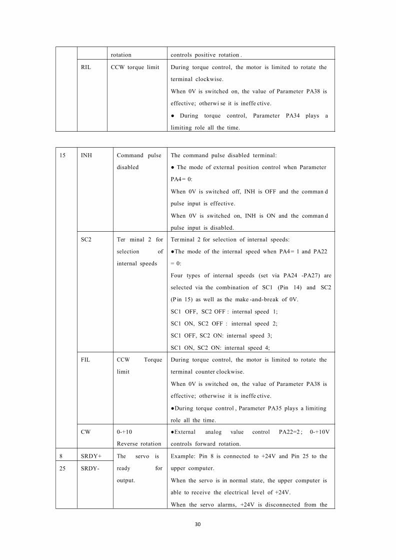
13 FSR CW
disabled
driver The servo motor is not allowed to rotate the terminal
clockwise.
● When Parameter PA20 = 0,
When 0V is switched off, FSR is OFF and the servo
motor can rotate clockwise.
When 0V is switched on, FSR is ON and the servo motor
is not allowed to rotate clockwise.
● Have the same function with a limit switch ; PA55 can
be set to normal open or normal close.
● Used in combination with Parameter PA20. When FSR
is 1, this function is shielded .
14 CLE Deviation
reset
counter Reset Terminal 1 of the position deviation counter:
● Under the mode of position control, namely when PA4
= 0,
When 0V is switched off, CLE is OFF and the counter
keeps displaying the value.
When 0V is switched in , CLE is ON and the counter
resets.
SC1 Ter minal 1 for
selection of
internal speed s
Terminal 1 for selection of internal speed s:
● The mode of the internal speed when PA4 =1 and PA22
= 0:
Four types of internal speeds are selected via the
combination of SC1 (P in 14) and SC2(Pin 15) as well as
the make-and -break of 0V.
SC1 OFF, SC2 OFF : internal speed 1;
SC1 ON, SC2 OFF : internal speed 2;
SC1 OFF, SC2 ON: internal speed 3;
SC1 ON, SC2 ON: internal speed 4;
Four types of speeds can be modified via PA24, PA25,
PA26 , and PA27 .
ZERO Zero speed
clamping
Reset terminal for the analog value of speed command:
● The mode of the external analog speed when PA4 = 1
and PA22 = 1:
ZERO is OFF when 0V is switched off, and the speed
command is an analog input value.
ZERO is ON when 0V is switched on, and the speed
command is reset to zero.
CCW 0-+10 positive ● External analog value control PA22=2 ; 0-+10V
30
rotation controls positive rotation .
RIL CCW torque limit During torque control, the motor is limited to rotate the
terminal clockwise.
When 0V is switched on, the value of Parameter PA38 is
effective; otherwi se it is ineffe ctive.
● During torque control, Parameter PA34 plays a
limiting role all the time.
15 INH Command pulse
disabled
The command pulse disabled terminal:
● The mode of external position control when Parameter
PA4= 0:
When 0V is switched off, INH is OFF and the comman d
pulse input is effective.
When 0V is switched on, INH is ON and the comman d
pulse input is disabled.
SC2 Ter minal 2 for
selection of
internal speeds
Terminal 2 for selection of internal speeds:
●The mode of the internal speed when PA4= 1 and PA22
= 0:
Four types of internal speeds (set via PA24 -PA27) are
selected via the combination of SC1 (Pin 14) and SC2
(P in 15) as well as the make -and-break of 0V.
SC1 OFF, SC2 OFF : internal speed 1;
SC1 ON, SC2 OFF : internal speed 2;
SC1 OFF, SC2 ON: internal speed 3;
SC1 ON, SC2 ON: internal speed 4;
FIL CCW Torque
limit
During torque control, the motor is limited to rotate the
terminal counter clockwise.
When 0V is switched on, the value of Parameter PA38 is
effective; otherwise it is ineffe ctive.
●During torque control , Parameter PA35 plays a limiting
role all the time.
CW 0-+10
Reverse rotation
●External analog value control PA22=2 ; 0-+10V
controls forward rotation.
8 SRDY+ The servo is
ready for
output.
Example: Pin 8 is connected to +24V and Pin 25 to the
upper computer.
When the servo is in normal state, the upper computer is
able to receive the electrical level of +24V.
When the servo alarms, +24V is disconnected from the
25 SRDY-

31
upper computer.
Example: Pin 25 is connecte d to 0V and Pin 8 to the
upper computer.
When the servo is in normal state, the upper computer is
able to receive the electrical level of 0V.
When the servo alarms, 0V is disconnected from the
upper computer (normal close).
●Electrical level inversion or normal open/ normal close
switching can be done via Parameter PA57.

32
Pin Mark Signal Name Function
26 ALM+ Servo alarm
output
Example: Pin 26 is connected to +24 V and Pin 27 to the
upper computer.
When the se rvo alarms, the upper computer is able to
receive the electrical level of +24V.
When the servo is in normal state, +24V is disconnected
from the upper computer.
Example: Pin 27 is connected to 0V and Pin 26 to the
upper computer.
When the servo is in no rmal state, the upper computer is
able to receive the electrical level of 0V.
When the servo alarms, 0V is disconnected from the
upper computer (normal close).
● Electrical level inversion or normal open/ normal
close switching can be done via Parameter PA57.
27 ALM-
28 COIN+ The second
reset ( used for
Siemens)
Positioning
done or speed
reached
Example: Pin 28 is connected to +24V and Pin 2 9 to the
upper computer.
When positioning is done, speed is reached, or in zero
position , the upper computer is able to receive the
electrical level of +24V; otherwise +24V is
disconnected from the upper computer.
Example: P in 29 is connected to 0V and Pin 28 to the
upp er computer.
When positioning is done, speed is reached, or in zero
position , the upper computer is able to receive the
electrical level of 0V; otherwise 0V is disconnected
from the upper computer.
● Electrical level inversion or normal open/ normal
close switching can be done via Parameter PA57.
● Primarily used for reset of Siemens 801 and 802
numeric controls in the mac hine tool industry.
29 COIN-
30 BRK+ Mechanical
brake
The output end of the band -type brake switch:
Example: Pin 30 is connected to +24V and Pin 31 to31 BRK-

33
(band -type
brake) ti ghtness
the positive pole of the relay coil.
After the motor is enabled, the coil of the intermediate
relay is able to receive the electrical level of +24V;
otherwise +24V is disconnected from the relay.
Example: P in 31 is connected to 0V and Pin 30 to the
negative pole of the relay coil.
After the motor is enabled, the coil of the intermediate
relay is able to receive the electrical level of 0V;
otherwise 0V is disconnected from the relay.
● Electrical level inversion or normal open/ normal
close switching can be done via Parameter PA57.
● PA47 is used to set delayed s witching on of the
band -type brake.
● PA48 is used to set enabled delayed switching off.

34
I+> OA+> Encoder's Phase
Aρ
The difference of ABZ signal of the encoder is output and
fed back by the driver to the upp er computer. +'
,2ρ OA+>
3ρ OB+> Encoder ’s Phase
B+>4ρ OB+>
5ρ OZ+> Encoder’s Phase
Zρ6+> OZ+>
7+> CZ+> Encoder's
Z-phase signal
is output by the
open circuit of
the collecting
electrode. +>
Us ed for setting to find out the zero p oint. There is or.ly
one Z-phase signal when the motor rotates for one 口rcle. •
Encoder’s Z-phase signal is output by the open circuit of
the collecting electrode. CZ is ON (electrified) when the
encoder’s Z-phase signal is output; otherwise CZ outputs
OFF. +>
9ρ GND+> Encoder's OV ρ Encoder’s OV (the common ground wire can share the
same ground wire with Pin 36). ’
36+> PE+> The ground wire
for the sl ielding
layer +>
To be connected with the housing Improve 副iti-
interfer ence by short cir cu 山ng PE with the digi:al
ground wire to ensure reliable grounding, according to
different upper computers.ρ

35
Definitions of CN2 interface and Encoder Input Signal
图 4.2 面对 CN2 26 芯插头焊片看
Figure 4.2 Front Elevation of 26-core Plug Soldering Terminal of CN2 Interface
Mark Signal Name Function
14,15,16,17 +5V +5V power supply for the encoder To provide power supply for theencoder (via shielded cables).
18,19,20,21,22,23 0V 0V ground wire for the encoder
1 A+ A+ input for the encoder To be connected to A+ of the servomotor.
2 A- A- input for the encoder To be connected to A- of the servomotor.
3 B+ A+ input for the encoder To be connected to B+ of the servomotor.
4 B- A- input for the encoder To be connected to B- of the servomotor.
5 Z+ A+ input for the encoder To be connected to Z+ of the servomotor.
6 Z- A- input for the encoder To be connected to Z- of the servomotor.
7 U + A+ input for the encoder To be connected to U+ of the servomotor.
8 U- A- input for the encoder To be connected to U- of the servomotor.
9 V+ A+ input for the encoder To be connected to V+ of the servomotor.
10 V- A- input for the encoder To be connected to V- of the servomotor.
11 W+ A+ input for the encoder To be connected to W+ of the servomotor.
12 W- A- input for the encoder To be connected to W- of the servomotor.

36
26 PE The ground wire for the shieldinglayer
To be connected with thehousing. Improve anti-interference by short circuitingP E with the digital ground wireto ensure reliable grounding,according to different uppercomputers.

37
Principle of the Input Interface for Switching Value
Figure 4.3-a Input Interface for Switching Value
Servo controller
● The input interface should be externally connected to a power supply of DC12V-24V with a
current equal to and more than 105MA.
● Inverse connection of the positive and negative poles may damage the driver and make it
unable to work normally.
Principle of the Output Interface for Switching Value
Figure 4.3-b Output Interface for Switching Value
Servo controller
● The maximum output voltage is 25V and the maximum output current is equal to and less than
55MA.

38
● Inverse connection of the positive and negative poles may damage the driver and make it
unable to work normally.
● The output load is a inductive component which should be inversely connected in parallel with
a fly-wheel diode (Make sure that the poles are properly connected; otherwise the driver will be
damaged. Inverse connection of the poles is equal to short circuit).
Principle of the Input Interface for Pulse Value
Figure 4.4-a Differential Output Mode of Pulse

39
Servo controller
Figure 4.4-b Single-ended Output Mode of Pulse
Servo controller
● The differential output mode of pulse is relatively reliable, so it is suggested to
use AM26LS31 and the like that are similar to a RS422 line driver.
● The power supply is provided externally under the single-ended output mode and the working
frequencywill lower. There are empirical data below:
Input voltage Vcc Series resistance R
24V 1.4K-2K
12V 500Ω-820Ω
5V 80Ω-120Ω

40
4.6.1 Input Mode of Pulse
Input Mode of
Pulse
CCW Operation CW Operation Parameter
Selection
Pulse + direction Parameter PA14=0
CCW pulse
CW pulseParameter PA14=1
AB-biphase
orthogonal pulseParameter PA14=2
Principe of the input interface of Analog Value
Figure 4.5-a Interface forAnalog Differential Input
上位机 Upper computer
伺服驱动器 Servo driver
AS+或AT+ AS+ orAT+ AS-或 AT- AS- orAT-

41
Figure 4.5-b Interface forAnalog Single-ended Input
上位机Upper computer
伺服驱动器 Servo driver
AS+或AT+ AS+ orAT+ AS-或 AT- AS- orAT-
Figure 4.5-c Input Interface forAnalog Differential Potentiometer
电位器 Potentiometer
伺服驱动器 Servo driver
AS+或AT+ AS+ orAT+ AS-或 AT- AS- orAT-

42
Figure 4.5-d Input Interface for Analog Single-ended Potentiometer
电位器 Potentiometer
伺服驱动器 Servo driver
AS+或AT+AS+ orAT+ AS-或 AT- AS- or AT-
● The input voltage of the analog value should not exceed the range of -10V-+10V; otherwise the driver will be
damaged.
● The analog value has a deviation indeed, because wires and the interface circuit, etc, weaken and are interfered.
It is suggested that a cable with a shielding layer be used for connection with its both ends grounded. Parameter
PA49 can be used to set the threshold voltage (unit: rpm).
●The analog value has a deviation indeed, so it must be adjusted. Parameter PA45 can be used to make
compensate for the deviation value.
Principe of Encoder Interface4.8.1 CN1 Output Interface for Encoder Signal (from the driver to the upper computer)
Figure 4.6 CN1 Output Interface for Encoder上位机接收 Upper computer receiving
伺服驱动器 Servo driver

43
● The signal of the encoder passes the differential driver AM26LS31 and is not an non-isolated output.
● The upper computer can receive the signal via AM26LS32 or a high-speed photocoupler.
CN2 Input Interface for Encoder Signal (from the servo motor to the driver)
图 4.7 CN2光电编码器输入接口
Figure 4.7 CN2 Input Interface for Photoelectric Encoder伺服电机编码器 Servo motor encoder
伺服驱动器 Servo driver
CN1 Output Interface for Z signal of the Encoder (from driver output to
zeroing by the upper computer)
Figure 4.8 CN 1 Output Interface for Z Signal of Photoelectric Encoder上位机 Upper computer
伺服驱动器 Servo driver
● The Z signal is a non-isolated signal which is output by the open circuit of the collecting electrode. The Z

44
signal of the encoder has conduction but no cut-off.
● The Z signal should be received via a high-speed photocoupler.

45
Remarks

46
Operation PanelThe operation panel is comprised of six LED digital tube displays
and four
keys ↑ , ↓ , ← and Enter, one red lamp Alm, and one green lamp,
which are used to display all kinds of statuses of the system and to set
parameters.
Operations are layered operations as follows:
图 5.1操作面板
Figure 5.1 Operation Panel
- referstotheback,exitandcancelofa layer;
refers to the advance, entry and confirmation of the hierarchy
↑ and ↓ refers to increasing or decreasing a sequence number or a value.
When the red indicating lamp Alm is on, it means that there is an alarm; and the alarm is displayed on the digital
tube.
When the green indicating lamp Run, it means the motor is in enable working state.
● When the decimal points at the lower right corner of the digital tube, it means a parameter is being modified.
● When the red indicating lamp Alm is on and the alarm number―Err--xx‖ is flashing, there is a driver
alarm. Cut off the power supply and find out the cause of the alarm.
ChapterVDisplay andOperation
Enter

47
Speed trial run mode
JOG operation mode
Open-circuit operation mode
Status monitoring mode------
------
------ Parameter management mode
------
------
------
------
------
Parameter modification mode
Components of Parameter StructureThe first layer is used for mode selection. There are totally seven modes. Press← to return the main menu.Use
↑ and ↓ to select a mode. Press Enter to enter the second layer of a selected mode. Press← to go back
to the first layer.
DP--
PA--
EE--
SR--
JR--
AU-- Analog value auto-zeroing
CO-- Encoder zeroing mode
OL--

48
DP-EPO
DP-EPO.
DP-TRQDP-- 1 -- Motor current(A)
CNE --C--position
-Speed command
DP-SPD --Motor speed r 1000 --1000 rpm
DPDP
-- Current position lower 5 digit→ P80829
-- Current position higher 5 digit → P
DP-CPO --Position command lower 5 digit
DP-CPO.--Position command higher 5 digit
--
E-- E
--80829 pulses
--110000 pulses
-
C --220000 pulses
9 --9 pulses10 -- 0pulses- Motor torque(70%)
1 4.5 -- Motor current(4.5A)
DP-LSP -- Z pulse count80829 -- the number of Z pulses DP-
urrent control modeCNE 0 -- Control mode 0 DP-FRQ
command frequencyr 1000 --1000rpm
DP- CS - r. 35 --Speed command 35rpm
DP- Ct --Torque commandt. 70 --
DP-APO --Rotor absolute positionA
DP--IN --Input terminal statuslnhllhl-- Input terminal status
DP-Out -- Output terminal statusoutllhl-- Output terminal status DP-
COD -- Encoder input signalcod lh-- Encoder signal
DP- RN --Operation statusrn -on -- Motor is running DP-ERR --Alarm codeErr 9 -- Alarm Code 9
Status MonitoringMode (DP- -)
C81410 81410 pulses
Position deviation lower 5 digitPosition deviation higher 5 digit
—Motor torque (%) T 60 -
Torque command 20%
3325 -- 3325 pulses
Table 5.2 Table of Monitoring
1. The input pulse value is a pulse that is magnified by an input electronic gear.
2. The unit of the pulse value is the unit of the internal pulse of the servo, 10000 pulses per revolution.
3. Display of Operation Statuses
―CN-OFF‖means that the heavy current for the servo is not switched on.
―CN-CH‖means that the heavy current for the servo is switched on, but enabling is not switched on.
―CN-ON‖ means that the heavy current for the servo and the enabling are switched on and that the servo is in
operation state.
4. The absolute position of the rotor in one revolution refers to the position of the rotor relative to the stator in one
revolution. One revolution is a cycle with a range of 0-9999. The electronic gear ratio is not used in calculations.
5. The display of the input terminal status is shown in the following figure:
Figure 5.2 Display of Input Terminal Status

49
INH(指令脉冲禁止)INH (command pulse disabled)SC2(速度选择 2)SC2 (speed selection 2) FIL(CCW转矩限制)FIL (CCW torque limit) RIL(CW转矩限制)RIL (CW toque limit) CLE(偏差计数器
清零)CLE (deviation counter reset) SC1(速度选择
1) SC1 (speed selection 1)
ZEROSPD(零速箝位) ZEROSPD (zero position clamping) RSTP(CW驱动禁止) RSTP (CW driver disabled) FSTP(CW驱动禁止) FSTP (CW driver disabled) ALRS(报警 清除)
ALRS (Alarm clearance)SRV-ON(伺服使能)SRV-ON(servo enable)
(When strokes lighten and there is signal input, the input terminal is ON; when it goes out, the input terminal is
disconnected to OFF.)
6. The display of the output terminal status is shown in the following figure:
Figure 5.3 Display of Input Terminal Status
(When strokes lighten and there is signal input, the input terminal is ON; when it goes out, the input terminal is
disconnected to OFF.)
保留 RetainedCOIN(定位完成)COIN (positioning done)SCMP(速度到达)SCMP(speed reached)ALM(伺服报警)ALM(servo alarm)SRDY 伺服准备好 SRDY(servo ready)
7. The display of the encoder status is shown in the following figure:

50
Figure 5.4 Status Display of Encoder Feedback Signal
(When strokes lighten and there is signal input, the encoder is ON; when it goes out, the encoder is disconnected
to OFF.)
编码器 U相
Encoder’s U-phase 编
码器 V 相 Encoder’s
V-phase 编码器W
相 Encoder’sW-
phase 编码器 Z相
Encoder’s Z-phase 编
码器 B相 Encoder’s
B-phase 编码器 A相
Encoder’sA-phase

51
ParameterModificationMode (PA--)Press to enter the parameter modification mode ―PA--‖ . Press ↑ and ↓ to increase or decrease a
parameter number. Press Enter to enter and modify a parameter. The decimal points at the lower right corner of
the digital tube will lighten when a parameter is being modified; and they will go out when Enter is pressed
again. Press ← to return.
Motor type code
PA--0 --Parameter password 385 -- User password
PA--1 --
51 --Stands for 15015 type motor
PA--4 --Control mode selection0 --Position control mode
Table 5.3 Operation of Parameter ModificationMode
ParameterManagementMode (EE--)Press Enter to enter the parameter management mode ―EE--‖ . Press ↑ and ↓ to increase or decrease a
parameter. Finding a menu that should be stored or restored and pressing Enter for more than 3 seconds will
make ―Finish‖ display, which means that the operation is successful and will be effective after power cut
off. ―Error--‖ will appear in case of failure or incorrect password.
EE--SET -- Store parameter Enter –Press down for more than 3 seconds
EE--RD -- Read parameter Enter –Press down for more than 3 seconds
EE—BA -- Backup parameterEnter –Press down for more than 3 seconds
P
EE--DEF –Restore default Enter – Press down for more than 3 seconds
Table 5.4 Operation of Parameter ManagementMode
1. EE—SET write in parameter. The password for Parameter PA—0 should be 315. EE—SET is mainly used to
store a parameter permanently.
2. EE—BD backup parameter means writing parameters with better effect in current servo state in the EEPROM
backup area and EE—RS is used in combination of EE—BD.
3. EE—BD restore backup means restoring the backup parameters in the backup area from EEPROM into a
parameter table.
4. EE—BD restore default is used to restore a default in case of parameter confusion or unclear reasons, etc.
when the new adaptive motor is debugged.
When restoring a default, find the corresponding motor model, set the password for PA—0 to 385 and PA--1 to the
type code corresponding to the motor, and then restore the default.
JOGOperationalMode (Jr- -)Press Enter to enter the jog operationmode―Jr--‖. Press Enter to enter jog operation mode―J--‖. The jog speed
is set via Parameter PA21.
EE—RS -- Restore backup Enter – ress down for more than 3 seconds
Ente

52
Jr--- -- Jog mode Enter –
Sr--- --Jog modeEnter –
AU--spd –Zeroing of Speed Analog ValueEnter – Start
be also modified manually and then stored manually.
AU--trq – Zeroing of Torque Analog Value Enter – Finish
be also modified manually and then stored manually.
J 200
Table 5.5 Operation of JOGOperational Mode
Speed TrialRun Mode (Sr- -)Press Enter to enter the speed trial run mode―Sr--‖. Press Enter to enter the jog operational mode―S--‖,
speed command and motor direction. Press ↑ and ↓ to change the magnitude and plus/minus of a value.
S -200
Table 5.6 Operation of Speed Trial Run Mode
Automatic ZeroingMode ofAnalog Value (AU- -)I. Zeroing of SpeedAnalog ValuePress to enter the analog value zeroing mode ―AU--spd‖ and press Enter again for more than 3 seconds
to enter the zeroing mode of speed analog value ―Start‖. After that, ―Finish‖ will be displayed and the
zero drift value will be automatically stored to PA45 (or PA39). Thereafter the zero drift value stored in PA45 (or
PA39) can
Table 5.7a Operation of Zeroing Mode of Speed Analog Value
● Parameter PA49 can be used to set the threshold voltage (unit: rpm).
II. Zeroing of TorqueAnalog Value
Press Enter to enter the analog value zeroing mode ―AU--trq‖ and press Enter again for more than 3 seconds
to enter the zeroing status of speed analog value ―Start‖. After that, ―Finish‖ will be displayed and the
zero drift value will be automatically stored to PA45 (or PA39). Thereafter the zero drift value stored in PA45 (or
PA39) can
Table 5.7b Operation of Zeroing Mode of Torque Analog Value
Automatic ZeroingMode of Encoder (CO- -)I.Automatic Zeroing of EncoderPress Enter to enter the zeroing mode of the encoder ―CO--‖. Press Enter again for more than 3 seconds and
the automatic zeroing of the encoder will start, and―Finish‖will be display when the automatic zeroing is
Enter

53
finished.

54
CO-- – Automatic zeroing of encoder Enter –
OL-- –Open loop operation Enter –
Finish
Table 5.8 Operation of Automatic Zeroing Mode of Encoder
● The automatic zeroing of the encoder is mainly used to check the angle of Z pulse after the encoder for the servo
driver is installed.
OpenLoop OperationModeI. Open Loop OperationPress Enter to enter the open loop operation mode―OL--‖. Press Enter again for more than 3 seconds and the
open loop operation mode starts up and the motor rotates.After that―Finish‖will be display.
Finish
Table 5.9 Operation of Open Loop Operation Mode
● The open loop operation is used to preliminarily determine whether the servo driver has obvious quality
problems such as abnormal assembly of the bearing and the rotor, etc.

55
ChapterVIParameters
List of Parameters [PA Mode]Parameter
No.
ParameterName Unit Range of Parameter Default
0 Parameter password * 0-9999 315
1 Motormodel * 0-52 50
2 Software version No. * * 98
3 Initial status display * 0-21 0
4 Controlmode selection * 0-6 0
5 Speed proportional gain Hz 50-500 150
6 Speed integral time constant mS 1-1000 20
7 Torque filter % 20-500 100
8 Speed detection filter % 20-500 100
9 Position proportional gain 1/S 1-500 40
10 Position feed-forward gain % 0-100 0
11 Cut-off frequency of position feed-forward filter Hz 1~1200 300
12 Count down numerator of position command * 1-32767 1
13 Count down denominator of position command * 1-32767 1
14 Input mode for position command pulse * 0-2 0
15 Reversion of the direction of position command
pulse
* 0-1 0
16 Positioningcompletion range Pulse 0-30000 20
17 Position overproof detection range x100 pulse 0-30000 400
18 Position overproof incorrect and ineffective * 0-1 0
19 Smoothing filter for position command 0.1mS 0-30000 0
20 Disabled input of Driver ineffective * 0~1 1
21 JOGoperation speed r/min -3000-3000 120
22 Selection of internal and external speeds * 0-2 1
23 Maximum speed limit r/min 0-4000 3600
24 Internal speed 1 r/min -3000-3000 0
25 Internal speed 2(motor zeroing current) r/min -3000-3000 100
26 Internal speed 3 r/min -3000-3000 300
27 Internal speed 4 r/min -3000-3000 -100
28 Arrival speed r/min 0-3000 500
29 Torque command input gain of analog value 0.1V/100% 10-100 50
30 User torque overload alarm value % 50-300 200
31 User torque overloadAlarm detection time mS 10-30000 0
32 Controlmode switching permissible * 0-1 0
33 Reversion of torque input direction of analogvalue
* 0-1 0
34 Internal CCW torque limit % 0-300 300*
35 Internal CW torque limit % -300-0 -300*

56
36 Command pulse signal filter factor * 0-3 1
37 Command direction signal filter factor * 0-3 0
38 External CCW and CW torque limit % 0-300 100
39 Zero drift compensation for analog value torquecommand
* -2000-2000 0
40 Acceleration time constant mS 1-10000 100
41 Deceleration timeconstant mS 1-10000 100
42 Alarm 15 shielded * 0-1 1
43 Analog speed command gain (r/min) / V 10-3000 300
44 Reversion ofAnalog speed command direction * 0-1 0
45 Zero drift compensation for Analog speedcommand
* -5000-5000 0
46 Analog speed command filter Hz 0-1000 300
47 Setting of the delayed conduction of theband-type brake when the motor is enabled.
×10mS 0-200 80
48 Setting of enable time delay when the band-typebrake of the motor is closed.
×10mS 0-200 0
49 Analog value voltage threshold value speedcontrol
r/min 0-3000 0
50 Speed limited during torque control r/min 0-5000 3600*
51 Dynamic electronic gear effective * 0-1 0
52 Count down numerator of the command on thesecondposition
* 1-32767 1
53 Lower 4 digit input terminal forced ON input Binary system 0000-1111 0000
54 Higher 4 digit input terminal forced ON input Binary system 0000-1111 0000
55 Lower 4 digit input terminal reversion setting Binary system 0000-1111 0000
56 Higher 4 digit input terminal reversion setting Binary system 0000-1111 0000
57 Controlword for output terminal reversion Binary system 0000-1111 0000
58 Time setting of DemonstrationMode 2 0.1S 1-30000 600

57
Detailed Explanation of ParametersParameter
No.
Parameter
Name
DetailedExplanation of Functions Range of parameter
[Default]
0 Parameter
password
a. The user password is 315.
b. The password for type code is 385 and only used for modifying Parameter
PA1.
c. The password for the motor manufacturer is 510 and parameters are
effective online (not recommended).
0-9999
[ 315 ]
1 Type code a. The type code is used to match different models of servo motors. Set the
servo according to Table 2.2 and then restore the factory value, which will be
effective only after power down.
b. Modify this parameter. Parameter PA0should be 385.
0-9999
[ 38 ]
2 Software
versionNo.
a. Only software version No. is displayed and read only.
b. Where the version No. is an odd number, the servo driver is all-function
type one; where the version No. is even number, the servo driver is a pulse
type one.
c. The all-function type has a function of analog value control, but the pulse
type hasn’t.
80-9999
[ 98 ]
3 Initial status The initial display status of the digital tube when the driver is switched on 0-19
display 0: Display motor speed [ 0 ]
1: Display the lower 5 digit at the current position
2: Display the higher 5 digit at the current position
3: Display the lower 5 digit of position command (command pulse
accumulation);
4: Display the higher 5 digit of position command (command pulse
accumulation);
5: Display the lower 5 digit of position deviation;
6: Display the higher 5 digit of position deviation;
7: Display motor torque;
8: Display motor current;
9: Display Z pulse count;
10: Display control mode;
11: Display position command pulse frequency;
12: Display speed command;
13: Display torque command;
14: Display the absolute position of the rotor in one revolution;
15: Display input terminal status;
16: Display output terminal status;
17: Display encoder input signal;
18: Display operation status;
19: Display alarm code;
4 Control mode
selection
0: Position control mode ;
1: Speed control mode:
a. The internal and external speeds are selected via Parameter PA22;
0-6
[ 0 ]
58
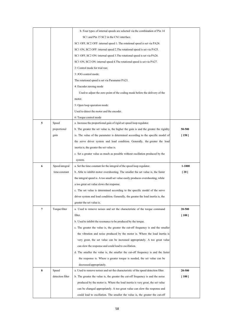
b. Four types of internal speeds are selected via the combination of Pin 14
SC1 and Pin 15 SC2 in the CN1 interface.
SC1 OFF, SC2 OFF: internal speed 1. The rotational speed is set via PA24.
SC1 ON, SC2 OFF: internal speed 2.The rotational speed is set via PA25.
SC1 OFF, SC2 ON: internal speed 3.The rotational speed is set via PA26.
SC1 ON, SC2 ON: internal speed 4.The rotational speed is set via PA27.
2: Control mode for trial run;
3: JOG control mode;
The rotational speed is set via Parameter PA21.
4: Encoder zeroing mode
Used to adjust the zero point of the coding mask before the delivery of the
motor.
5: Open loop operation mode:
Used to detect the motor and the encoder.
6: Torque control mode
5 Speed
proportional
gain
a. Increase the proportional gain of rigid set speed loop regulator.
b. The greater the set value is, the higher the gain is and the greater the rigidity
is. The value of the parameter is determined according to the specific model of
the servo driver system and load condition. Generally, the greater the load
inertia is, the greater the set value is.
c. Set a greater value as much as possible without oscillation produced by the
system.
50-500
[ 150 ]
6 Speed integral a. Set the time constant for the integral of the speed loop regulator. 1-1000
timeconstant b. Able to inhibit motor overshooting. The smaller the set value is, the faster [ 20 ]
the integral speed is. A too small set value easily produces overshooting, while
a too great set value slows the response.
c. The set value is determined according to the specific model of the servo
driver system and load condition. Generally, the greater the load inertia is, the
greater the set value is.
7 Torque filter a. Used to remove noises and set the characteristic of the torque command
filter.
b. Used to inhibit the resonance to be produced by the torque.
c. The greater the value is, the greater the cut-off frequency is and the smaller
the vibration and noise produced by the motor is. Where the load inertia is
very great, the set value can be increased appropriately. A too great value
can slow the response and could lead to oscillation.
d. The smaller the value is, the smaller the cut-off frequency is and the faster
the response is. Where a greater torque is needed, the set value can be
decreasedappropriately.
20-500
[ 100 ]
8 Speed a. Used to remove noises and set the characteristic of the speed detection filter. 20-500
detection filter b. The greater the value is, the greater the cut-off frequency is and the noise [ 100 ]
produced by the motor is. Where the load inertia is very great, the set value
can be changed appropriately. A too great value can slow the response and
could lead to oscillation. The smaller the value is, the greater the cut-off

59
frequency is and the faster the speed feedback response is. Where a faster
speed response is needed, the set value can be decreased appropriately.
9 Position
proportional
gain
a. Used to set the proportional gain of the position loop regulator.
b. The greater the set value is, the greater the gain is, the greater the rigidity is,
and the smaller the hysteretic value of position under the same condition of
frequency command pulse. However, A too great set value may lead to
oscillation or overshooting.
c. The value of the parameter is determined according to the specific model of
the servo driver system and load condition.
1-500
[ 40 ]
10 Position
feed-forward
gain
a. Used to set the feed-forward gain of the position loop.
b. When the feed-forward gain is set to 100%, it means that the hysteretic
value of position is always zero under the command pulse of any frequency.
c. Increase of feed-forward gain of the position loop is able to improve the
high speed response characteristic of the control system, but it makes the
position loop of the control system unstable and easily produce oscillation.
d. The feed-forward of the position loop generally is zero unless a very high
response characteristic is needed.
0-100
[ 0 ]
11 Cut-off
frequency of
position
feed-forward
filter
a. Used to set the cut-off frequency of the low-pass filter of the position loop
feed-forward value.
b. The function of this filter is to increase the stability of composite position
control.
1-1200
[ 300 ]
12 Count down
numerator of
position
command
a. Where the program of the system makes lead screw move 5 mm (5000
pulses), the motor needs to rotate one revolution.
PA12/PA13=Pulse numerator/Pulse denominator= Actual feedback/Command
pulse
=The number of wires for the motor encoder (2500 wires) x the number of
frequency doublings (4)
=10000/5000=2/1
b. Where the motor is connected directly to the lead screw with a pitch of
6mm:
PA12/PA13=10/leadscrewpitch(6)=5/3
Note: a NC machine can be set more visually by referring to b.
Range of gear ratio: 1/100≤G≤100
1-32767
[1 ]
13 Count down
denominator
of position
command
1-32767
[ 1 ]
14 Input mode
for position
Three types of pulse input modes can be set:
0: pulse + sign
0-2
[ 0 ]

60
command
pulse
1: CCWpulse/CW pulse;
2: Two-phaseorthogonal pulse input.
See Figure 4.4-c Pulse Mode on Page 28.
15 Reversion of 0: Default direction. 0-1
the direction 1: Direction reversion. [ 0 ]
of position
command
pulse
16 Positioning
completion
range
a. When the value in the position deviation counter is less than or equal to the
set value during position control, positioning completion is COIN ON;
otherwise it is OFF.
b. The positioning completion range is a speed arrival signal in other control
modes.
0-3000
[ 20 ]
17 Position When the count value of the position deviation counter is more than the set 0-3000
overproof value of this parameter under the mode of position control, the servo driver [ 400 ]
detection alarms.
range
18 Position 0: Detection is effective. 0-1
overproof 1: The shielding position is overproof, Parameter 4 alarms and Parameter [ 0 ]
incorrect and PA17 is ineffective.
ineffective
19 Smoothing Mainly for PC no acceleration and deceleration,not with exponential form of 0-3000
filter for acceleration and deceleration.This parameter can be used for smooth filtering [ 0 ]
position of command pulse and optimize acceleration and deceleration.
command This filter loses no pulses, but the execution speed is possible to be delayed.
20 Disabled input 0: The disable inputs of CCW and CW are effective. 0-1of Driverineffective 1: The disable inputs of CCW and CW are ineffective. [ 1 ]
21 JOG operation
speed
The setting of forward and reverse speeds when the JOGmode is set -3000-3000
[ 120 ]
22 Selection of 0: This parameter is got from an internal speed. 0-2
internal and 1: This parameter is got from an external analog value (-10V-+10V). [ 1 ]
external 2: This parameter is got from an external analog value (0-+10V; Pins 14 and
speeds 15 are used to control forward and reverse directions.
23 Maximum The setting of the maximum speed limit of the servo motor is related to the 0-5000
speed limit servo motor. The maximum speed of the motor should be set according to the [ 3600 ]
adaptive model of PA1.
24 Internal speed When PA4=1and P22 =0: When Pin CNISC1 is OFF and Pin SC2 is OFF, this -3000-3000
1/zeroing parameter is internal speed 1. [ 0 ]
current
25 Internal speed a. When PA4=1and PA22=0 -3000-3000
2 When Pin CNISC1 is ON and Pin SC2 is OFF, this parameter is internal speed [ 100 ]
2.
b. When PA4 is equal to 4, set the percentage of the motor zeroing current.
26 Internal speed When PA4=1and PA22=0: -3000-3000

61
3 When Pin CNISC1 is OFF and Pin SC2 is ON, this parameter is internal speed
3.
[ 300 ]
27 Internal speed When PA4=1and PA22=0 : -3000-3000
4 When Pin CNISC1 is ON and Pin SC2 is ON, this parameter is internal speed [ -100 ]
4.
28 Arrival speed In non-position mode:
When the motor speed is more than this set value, COIN is O; otherwise COIN
is OFF.
This parameter is only used for determination of the motor speed and has no
directivity.
0-3000
[ 500 ]
29 Torque
command
input gain of
analogvalue
a. Used to set the proportional relation between the input voltage of analog
value torque and the actual operation torque of the motor;
b. The unit of the set value is 0.1V/100%;
c. The default value is 50, which corresponds to 5V/100%, namely inputting
5V voltage will produce 100% rated torque.
10-100
[ 50 ]
30 User torque
overload
alarm value
① Used to set the overload value of the user torque. This value is the
percentage of the rated torque. The limited values of the torque have no
directivity and both forward and reverse limited values are protected.
② When PA31>0, motor torque >PA30 and the duration >PA31, the driver
alarms with an Alarm No. Err-29 and stops rotating. After the alarm, the
driver must be electrified again to clear the alarm.
0-300
[200 ]
31 User torque The unit of the user torque overload detection time is millisecond; 0-30000
overload When this time is zero, the alarm function of the user torque overload is [0 ]
Alarm ineffective.
detection time
32 Controlmode
switching
permissible
0: Pin 11(A-CLA) of CN1 is only effective for alarm clearance.
1: When Parameter PA=0, Pin 11 (A-CLA) of CN1 is only effective for
switching of position and speed (default position effective).
When Parameter PA 4=1, Pin 11 (A-CLA) of CN1 is only effective for
switching of speed and torque (default position effective).
When Parameter PA 4=6, Pin 11 (A-CLA) of CN1 is only effective for
switching of torque and position (default position effective).
0-1
[ 0 ]
33 Reversion of
torque input
direction of
analogvalue
Used for reversion of the torque input polarity of analog value.
0: When the torque command of the analog value is positive, the torque
direction is CCW;
1: When the speed command of the analog value is positive, the torque
direction is CW;
0-1
[ 0 ]
34 InternalCCW Used to set the percentage of the internal torque limit of the motor CCW 0-300
torque limit direction. [ 250 ]
Example: If this parameter is set to two times of the rated torque, the set value
is 200;
This set value is limited and effective all the time.
35 InternalCW Used to set the percentage of the internal torque limit of the motor CW 0- -300
torque limit direction. [ -250 ]

62
Example: If this parameter is set to two times of the rated torque, the set value
is 200;
This set value is limited and effective all the time.
36 Command When PA4=0, this parameter is effective during position control. 0-3
pulse signal The greater the set value is, the strong the anti-interference to the command [ 1 ]
filter factor pulse is; at the same time, the smaller received pulse frequency could make the
pulse unable to be received.
Make adjustment to the advance and lag of the time sequence of the pulse and
the direction signal.
37 Command When PA4=0, , this parameter is effective during position control. 0-3
direction Make adjustment to the advance and lag of the time sequence of the pulse and [ 0 ]
signal filter the direction signal.
factor
38 External When PA4=6, Pin 14 or Pin 15 of CN1 is connected with 0V: 0-300torque limit
CCW, CW torque percentage limit, positive and negative effect at the same [ 100 ]
time .
PA38 is less than the set values PA34 and PA35.
39 Zero drift The zero drift compensation value to the analog value torque input is namely -2000-2000
compensation positive and negative offsets. [ 0 ]
for analog
value torque
command
40 Acceleration The set value means the acceleration time of the motor from 0-1000r/min. 1-10000
timeconstant Linear acceleration and deceleration characteristics are only used for the speed [ 100 ]
controlmode.
If the upper computer has acceleration and deceleration characteristics, this
parameter should be set to zero.
41 Deceleration The set value means the deceleration time of the motor from 1000-0r/min. 1-10000
timeconstant Linear acceleration and deceleration characteristics are only used for the speed [ 100 ]
controlmode.
If the upper computer has acceleration and deceleration characteristics, this
parameter should be set to zero.
42 Alarm 15 0: Alarm 15 takes effect. 1:Alarm 15 is shielded. 0-1
shielded Enhance the anti-interference of the UVW signal of the motor encoder. [ 1 ]
43 Analog value Used to set the proportional relation between the speed input voltage of analog 10-3000
speed value and the actual operation speed of the motor. [ 300 ]
command gain Example: ±10V voltage corresponds to positive and negative 3000revolutions
and can be set to 3000/10 =300 r/min/v; namely 1V corresponds to 300
revolutions.
44 Reversion of Used for reversion of the speed input ofAnalog value. 0-1
Analog value 0: When the speed command of the analog value is positive, the speed [ 0 ]
speed direction is CCW;
command 1: When the speed command of the analog value is positive, the speed
direction direction is CW;
63
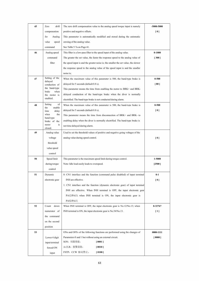
45 Zero drift The zero drift compensation value to the analog speed torque input is namely -5000-5000
compensation positive and negative offsets. [ 0 ]
for Analog This parameter is automatically modified and stored during the automatic
value speed zeroing of the analog value.
command See Table 5.7a on Page 41.
46 Analog speed This filter is a low-pass filter to the speed input of the analog value. 0-1000
command The greater the set value, the faster the response speed to the analog value of [ 300 ]
filter the speed input is and the greater noise is; the smaller the set value, the slower
the response speed to the analog value of the speed input is and the smaller
noise is;
47 Setting of the When the maximum value of this parameter is 500, the band-type brake is 0-500delayedconduction of delayed for 5 seconds (default 0.8 s). [ 80 ]
the band-type This parameter means the time from enabling the motor to BRK+ and BRK-brake whenthe motor is delayed conduction of the band-type brake when the diver is normallyenabled. electrified. The band-type brake is not conducted during alarm.
48 Setting of When the maximum value of this parameter is 500, the band-type brake is 0-500the enabletime delay delayed for 5 seconds (default 0.8 s). [ 0 ]
when the This parameter means the time from disconnection of BRK+ and BRK- toband-typebrake of the enabling delay when the diver is normally electrified. The band-type brake ismotor is not time delayed during alarm.closed.
49 Analog value
voltage
threshold
value speed
control
Used to set the threshold values of positive and negative going voltages of the
analog value during speed control. [ 0 ]
50 Speed limit This parameter is the maximum speed limit during torque control. 1-5000
during torque Note: Idle load easily leads to overspeed. [2500 ]
control
51 Dynamic
electronic gear
0: CN1 interface and the function (command pulse disabled) of input terminal
INH are effective.
1: CN1 interface and the function (dynamic electronic gear) of input terminal
INH are effective. When INH terminal is OFF, the input electronic gear
PA12/PA13; when INH terminal is ON, the input electronic gear is
PA52/PA13.
0-1
[ 0 ]
52 Count down When INH terminal is OFF, the input electronic gear is No.12/No.13; when 0-32767
numerator of INH terminal is ON, the input electronic gear is No.54/No.13. [ 1 ]
the command
on the second
position
53
Lower 4 digit
ONs and OFFs of the following functions are performed using the changes of 0000-1111
Parameters 0 and 1 but without using an external circuit. [ 0000 ]
input terminal SON:伺服使能; [ 0001 ]
forced ON A-CLR:报警清除; [ 0010 ]
input FSTP:CCW 驱动禁止; [ 0100 ]

64
RSTP:CW 驱动禁止; [ 1000 ]
SON: Servo enable: [ 0001 ]
A-CLR:Alarm clearance [ 0010 ]
FSTP: CCW driver disabled [ 0100 ]
RSTP: CWdriver disabled [ 1000 ]
54 Higher 4 digit CLE/SC1/ZEROSPD: 0000-1111
terminal Deviation counter reset/speed selection 1/zero speed clamping: [ 0001 ] [ 0000 ]
forced ON INH/SC2: command pulse disabled/speed selection 2 [ 0010 ]
input FIL: CCW torque limit [ 0100 ]
RIL: CW torque limit [ 1000 ]
55 Lower 4 digit To realize the reversion of the functions using the changes of Parameters 0 and 0000-1111
input terminal 1 (namely the reversion of the original external switch circuit input; normal [ 0000 ]
logic open changes to normal close and normal close changes to normal open).
reversion SON: servo enable [ 0001 ]
A-CLR:Alarm clearance [ 0010 ]
FSTP: CCW driver disabled [ 0100 ]
RSTP: CWdriver disabled [ 1000 ]
56 Higher 4 digit To realize the reversion of the functions using the changes of Parameters 0 and 0000-1111
input terminal 1 (namely the reversion of the original external switch input circuit; normal [ 0000 ]
logic open changes to normal close and normal close changes to normal open).
reversion CLE/SC1/ZEROSPD: deviation counter reset
Speed selection 1/zero speed clamping; [ 0001 ]
INH/SC2: command pulse disabled/speed selection 2; [ 0010 ]
FIL: CCW torque limit [ 0100 ]
RIL: CW torque limit [ 1000 ]
57 Output To realize the reversion of the functions using the changes of Parameters 0 and 0000-1111
terminal logic 1 (namely the reversion of the original external switch input circuit; normal [ 0010 ]
reversion open changes to normal close and normal close changes to normal open).
SRDY: servo ready; [ 0001]
ALM: servo alarm; [ 0010 ]
COIN: positioning completed/speed reached; [ 0100]
BRK: motor band-type brake; [ 1000 ]
58 Time setting Used to set the high-speed ageing time of the servo motor (unit: 0.1minute) in 1-30000
of demonstrationmode 2. [ 600 ]
Demonstration
Mode 2

65
Remarks
It is hereby declared that:● PA-59 can reach PA-299 at most in default in the parameterstructure ofMG -1000 series of servo drivers. The internal superpassword of the manufacturer or the password of the cooperationmanufacturer of the servo motor should be input.
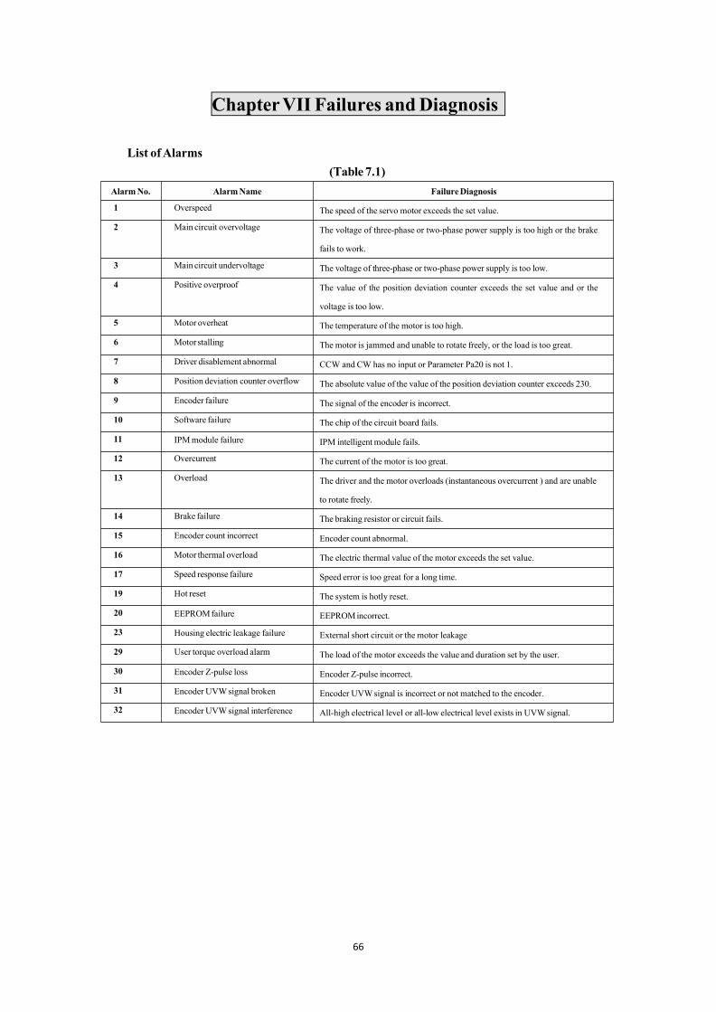
66
ChapterVII Failures andDiagnosis
List ofAlarms(Table 7.1)
AlarmNo. AlarmName FailureDiagnosis
1 Overspeed The speed of the servo motor exceeds the set value.
2 Main circuit overvoltage The voltage of three-phase or two-phase power supply is too high or the brake
fails to work.
3 Main circuit undervoltage The voltage of three-phase or two-phase power supply is too low.
4 Positive overproof The value of the position deviation counter exceeds the set value and or the
voltage is too low.
5 Motor overheat The temperature of the motor is too high.
6 Motorstalling The motor is jammed and unable to rotate freely, or the load is too great.
7 Driver disablement abnormal CCW and CW has no input or Parameter Pa20 is not 1.
8 Position deviation counter overflow The absolute value of the value of the position deviation counter exceeds 230.
9 Encoder failure The signal of the encoder is incorrect.
10 Software failure The chip of the circuit board fails.
11 IPMmodule failure IPM intelligent module fails.
12 Overcurrent The current of the motor is too great.
13 Overload The driver and the motor overloads (instantaneous overcurrent ) and are unable
to rotate freely.
14 Brake failure The braking resistor or circuit fails.
15 Encoder count incorrect Encoder count abnormal.
16 Motor thermal overload The electric thermal value of the motor exceeds the set value.
17 Speed response failure Speed error is too great for a long time.
19 Hot reset The system is hotly reset.
20 EEPROMfailure EEPROMincorrect.
23 Housing electric leakage failure External short circuit or the motor leakage
29 User torque overload alarm The load of the motor exceeds the value and duration set by the user.
30 Encoder Z-pulse loss Encoder Z-pulse incorrect.
31 Encoder UVWsignal broken Encoder UVWsignal is incorrect or not matched to the encoder.
32 Encoder UVWsignal interference All-high electrical level or all-low electrical level exists in UVWsignal.

67
Troubleshooting(Table 7.2)
In operation ●Motor power too small ★ Replace the current motor by a
Alarm
No.
AlarmName Operation
Status
Cause Solution
1 Overspeed Power on ●Driver or motor failure ★Replace the driver.
●Check parameters ★Checkwhether internal enable
Being enabled ●Short circuit between motor and
UVW
★ Check the wire of the motor.
●Encoder Position 0 deviation ★Motor encoder zeroing
● The parameters of the servo incorrect ★ Restore the parameters
During the
operation of the
motor
● Motor connector short circuited ★Check that there is no water in the
motor connector.
●Command speed of too fast ★Reduce the command speed.
●Acceleration/decelerationunstable ★Adjust the acceleration/deceleration
constant.
●Load too great ★Reduce the load.
2 Main circuit
overvoltage
Power on ● Power supply voltage too high ★Reduce the voltage.
● Power supplywaveform abnormal ★Replace the power supply.
● Servo driver failure ★Replace the servo driver.
In operation ●Circuit board failure ★ Replace the servo driver.
● Braking circuit failure ★Check the braking resistor.
3 Main circuit
undervoltage
Being enabled ● Main power supply voltage too low ★ Replace the power supply.
●Circuit board failure ★Replace the servo driver.
●Soft start circuit failure ★Replace the servo driver.
In operation ● transformer capacity insufficient ★Increase the transformer capacity.
●Power supplywire loose ★ Tighten wiring terminals
●Circuit board failure ★Replace the servo driver.
4 Position
overproof
In operation ● Command speed too faster ★Reduce the command speed.
● Input voltage too low ★ Check R/S/T power supply.
● Parameter PA17 too small. ★Increase the parameter
appropriately.
●Wire loose ★ Check and tighten the wire.
5
6
Motor overheat
Motor stalling
Power on ● Motor damaged ★ Replace the motor.
● Sensor wire broken ★Check the wire and replace the
sensor.
In operation
● Motor interface short circuitedhigh-powermotor.★Take waterproof and dustproof
● Servo parameters incorrect
measures.★Match a right motor model.
●transmission partially jammed ★ Disconnect the mechanical part.
●Load too great ★ Reduce the load
●Motor failure ★Replace the motor.

68
7 Disable
abnormal
Power on ● Check parameters and wires ★PA20,CW and CWWwires
8 Position
deviation
counter overflow
In operation ● Motor stalling ★Check the load.
● Command frequency abnormal ★ Reduce the speed of the upper
computer.
●Wiring incorrect ★Check the wire and connect the
shielding layer.
9 Encoder failure Power on ●Encoderwiring incorrect ★ Connect the wire correctly.
●Encoderdamaged ★ The encoder is a fragile article and
should be replaced.
● Encoder 5V voltage low ★Shorten the wire or replace the
driver.
In operation ● CN2 connector contact poor ★Tighten the CN2 connector.
●Hidden trouble exists in cable faulty
welding.
★Replace the cable.
10 Software failure Power on ●softwaredownloadmismatching ★Update the software.
●The chip of the circuit board failure ★Find out the interference and replace
the driver.
11 IPM module
failure
Power on ●Circuit board failure ★Replace the servo driver.
● Short circuit between U, V and W of
the motor
★ Check the wire and replace the
motor.
In operation ● Motor failure ★Check the wire and replace the
motor.
● Poor connection to power supply ★ Check the wire and prevent
interference.
12 Overcurrent Power on or in
operation
● Motordamaged ★Replace the motor.
●Short circuit between U, V andW ★Check the wire and replace the servo
driver.
●Overload ★Replace the current motor by a
high-powermotor.
13 Overload Power on ● The motor is damaged and water has
entered the motor.
★Replace the motor.
●Circuit board failure ★Replace the servo driver.
In operation ● Mechanical load too great ★Reduce the load.
●Mechanical transmission not freely ★Check Mechanical transmission
parts.
●Short circuit between U, V andW ★Check the cable.
●The band-type brake fails to loosen. ★Ensure that power supply for the
band-type brake is stable.
14 Brake failure Power on ●Circuit board failure ★Replace the servo.
In operation ●Braking resistor damaged ★Check the wire of the braking
resistor.
●Braking capacity insufficient ★ Prolong the

69
acceleration/deceleration time.
●Mechanical inertia too great ★Reduce themechanical inertia.
15 Encoder count
incorrect
In operation ● Encoder damaged ★Replace the encoder.
●Encoderwiring incorrect ★Check the wiring and replace the
encoder.
● Encoder power supply unstable ★5Vvoltage should be stable.
●The number of encoder wires
incorrect
★Adjust the number of wires
corresponding to the parameter.
16 Motor thermal
overload
Power on ● Servo parameter incorrect ★ Restore the factory value.
In operation ●Mechanical transmission not freely ★Add lubricant and reduce load.
●Overload time long ★Reduce load; start/stop are smooth.
17 Speed response
failure
In operation ● Long-time error too great ★Adjust parameter position
feed-forward.
●Start/start time too short ★Adjust the acceleration/deceleration
time.
19 Hot reset In operation ● Power supply unstable ★ Check power supply and wiring.
20 ROM alarm In operation ● Parameter storage alarm ★Restore the parameter and replace
the servo.
23 Electric leakagefailure
In operation ●Short circuit or motor leakage ★Check the wiring or replace the
motor.
29 Torque
insufficient
In operation ● Set torque exceeded ★Check Parameters PA30and PA31.
● Check the model selection of the
motor.
★Readapt the motor again.
● Mechanicaloverload ★ Disconnect the load and try again.
30 Encoder Z-pulse
loss
In operation ●Z-pulse doesn’t exit. ★Replace the encoder.
●Cable weld line incorrect ★Check the weld line.
●5V Voltageunstable ★Shorten the wire and reduce
attenuation.
●Poor shielding leads to interference. ★Well ground the shielding layer.
31 Encoder UVW
signal incorrect
In operation ●UVWpulse doesn’t exit. ★Replace the encoder.
●Cable weld line incorrect ★Check the weld line.
●5V Voltageunstable ★Shorten the wire and reduce
attenuation.
●Poor shielding leads to interference. ★Well ground the shielding layer.
32 Encoder UVW
signal angle
misplacement
In operation ●UVWpulse doesn’t exit. ★Replace the encoder.
●Encodermodel incorrect ★Check the encoder model.
●Weld line misplacement ★Check the weld line.
●5V Voltageunstable ★Shorten the wire and reduce
attenuation.
●Poor shielding leads to interference. ★Well ground the shielding layer.
● Where the Alm red lamp is on and the Alarm―Err--xx‖ in the digital tube flashes, the alarm is a driver alarm.
Cut off the power in time and find out the cause of the alarm.

70
Remarks

71
ChapterVIIIDebugging andApplication
Notices to Quick DebuggingI. Confirm that wiring is correct.
● R, S, T and U, V,W should not be connected reversely and loosely.
● Check whether the input voltage is three-phase 220V or single-phase 220V.
● Check that Pin 18 in CN1 interface is correctly connected with +24V and that Pins 36 and 9 in CN1
interface are correctly connected with 0V.Poles should not be connected reversely.
● Check that +5V in CN2 interface is correctly connected. Poles should not be connected reversely.
● Check whether the cable for the motor is short circuited or grounded.
● The wiring for the same motor should correspond to the same driver.II. etermineEnergizing Sequence.
● The heavy current and control electricity ofMG-1000 series of servos are electrified at the same time.
● If the brake of the band-type brake motor is not controlled by the servo, the brake should not be
electrified until the servo is enabled for more than 1 second. Only in this way can the position
precision and safety of the equipment be guaranteed.
● Due to integrated design of the heavy current and control ofMG-1000 series of servos and adoption ofpower-down delay discharge, the internal heavy current is immediately cut off after power supply is
cut off and the delay discharge of display and control circuits automatically cuts off after several
seconds.
For successful use ofMG -1000 series of drivers, please carefully read the sequence diagram below:
Figure 8.1 Sequence Diagram for Energizing andAlarm
控制回路及主电路电源 断电 1秒 通电
Control circuit andmain circuit power supply Power down
伺服报警输出(ALM) 报警 无报警
1s Power on
Servo alarm output (ALM) Alarm No alarm
伺服准备好输出(SRDY) 无准备好 10毫秒 准备好

72
PA--4 –-Control mode
–-Electronic gear numerator Factory value=1
PA-13 –- Electronic gear denominator Factory value=1
PA-20 –-Driver enable ineffectiveFactory value=1
PA--5 –-Speed proportional gain actory value=150
PA--6 –-Speed integral time constant
PA—7 –-Torque filter
Factory value=100
Factory value=100
PA-12
PA--9 –- Position proportional gain Factory value=40
PA-10 –-Position Feed-forward gain Factory value=0
Servo ready for output (SRDY) Not ready 10ms Ready
伺服使能(SON)
Servo enable (SON)
不使能 10毫秒
Failure to enable 1ms
使能
enabled
电机电流 不通电(自由状态) 1秒 通电(电机锁住)
Motor current Not electrified (free state) 1s Power on (motor locked)
电机抱闸 无电(抱闸紧) 有电(抱闸松)
Motor band-type brake without power (the brake tight) with power (the brake loose)
Position Control (Quick adjustment of parameters after power on)Example:AMG-1000/3Adriver matches a 130ST-M15015motor (position control).
1. Make ensure that the three-phase 220V voltage between R, S and T is correct after power on.
2. Do not connect the servo enable signal temporarily. Check whether there is any alarm and observe the
red lamp (ALM). If the red lamp is not on, the operation is normally and you can go to the next step.
3. Start the adaptation of parameters.
a. Enter the parameter modification mode to change PA-0 into ―385‖ password and then
change Parameter PA-1 into―51‖ corresponding to the motor type code (see Table 2.21 on
Page 10).
b. Enter the parameter management mode ―EE--‖, transfer to ―DP-def‖ and then press down
Enter for three seconds. When ―Finish‖ appears, it means the default value has been restored
according to the current adapted motor and will be effective only after power down.
c. After power on again, check several key parameters (See Table 8.1 below) of position control and
confirm that they are correct; the upper computer can send out an enable signal (or internal enable)
and send out an pulse after the green lamp (RUN) is on. Observe the dynamic effect of the motor,
appropriately modify the gain and adjust the characteristic of the motor.
Factory value = 0
Factory value=2
PA--8 –- Speed detection filter
Table 8.1 Adjustment of Key Parameters of Position Control
Speed Control (Quick adjustment of parameters after power on)Example: AMG-1000/3A driver matches a 130ST-M10015 motor (speed control)
1. Confirm that the three-phase 220V voltage between R, S and T is correct after power on.
2. Confirm that the wiring of the differential input of the speed analog value or the single-ended input is

73
Control mode Set to 1
Factory value=1
Set as required
Set as required
Internal speed command selectionSet
PA--4 –
PA--20--Driver disablement ineffective
PA-22 –
PA-40 –Acceleration time constantet as
PA-41 –Deceleration time constant
Analog speed command gainSet as required
PA-45 -- Analog speed zero drift compensation
PA-43–
correct.
3. Do not connect the servo enable signal temporarily. Check whether there is any alarm and observe the red
lamp (ALM). If the red lamp is not on, the operation is normally and you can go to the next step.
4. Start the adaptation of parameters.
a. Enter the parameter modification mode to change PA-0 into ― 385‖ password and then change
ParameterPA-1 into―49‖ as the motor type code (see Table 2.2 on Page 8).
b. Enter the parameter management mode ―EE--‖, transfer to ―DP-def‖ and then press down Enter
for three seconds. When ―Finish‖ appears, it means the default value has been restored according
to the current adapted motor and will be effective only after power down.
c. After power on again, check several key parameters (See Table 8.2 below) of speed control and
confirm that they are correct; the upper computer can send out an enable signal (or internal enable), and
send out an analog signal after the green lamp (Run) is on and after automatic zeroing. Observe the
dynamic effect of the motor, appropriately modify the gain and adjust the zero drift value.
Table 8.2Adjustment of Key Parameters of Speed Control
Torque Control (Quick adjustment of parameters after power on)Example: AMG-1000/3A driver matches a 110ST-M06030 motor (torque control).
1. Confirm that the three-phase 220V voltage between R, S and T is correct after power on.
2. Confirm that the wiring of the differential input of the torque analog value or the single-ended input is
correct.
3. Do not connect the servo enable signal temporarily. Check whether there is any alarm and observe the red
lamp (ALM). If the red lamp is not on, the operation is normally and you can go to the next step.
4. Start the adaptation of parameters.
a. Enter the parameter modification mode to change PA-0 into―385‖ password and then change Parameter
PA-1 into―38‖ corresponding to the motor type code (see Table 2.2 on Page8).
b. Enter the parameter management mode ―EE--‖, transfer to ―DP-def‖ and then press down Enter
for three seconds. When ―Finish‖ appears, it means the default value has been restored according
to the current adapted motor and will be effective only after power down.
c. After power on again, check several key parameters (See Table 8.2 below) of torque control and
confirm that they are correct; the upper computer can send out an enable signal (or internal enable), and
send out an analog value signal after the green lamp (RUN) is on and after automatic zeroing. Observe
the dynamic effect of the motor, appropriately modify the gain and adjust the zero drift value.

74
PA--4 --Control mode
PA--20—Driver disablement ineffective Factory value =1
PA-12 --
PA-13 -- Electronic gear denominator
PA-52 -- Numerator of the second electronic gear ratio
Set to zero
Set to 6
Factory value=1
Set as required
Set as required
Set as required
PA--4 --Control mode
PA--20--Driver disablement ineffective
PA-40 -- Acceleration time constantSet as required
PA-41 -- Deceleration time constant
PA-43 -- Analog speed command gain
PA-45 -- Analog speed zero drift compensation
Table 8.3 Adjustment of Key Parameters of Torque Control
Dynamic ElectronicApplication● Mainly used for application of position control.
●Dynamic electronic application
Dynamic electronic application refers to dynamically switching the electronic gear proportion via the
make-and-break of the input terminal during the operation of the servo driver.
● It is mainly reflected on the limit of the maximum output frequency of the upper computer. When the
proportion value of the electronic gear is very small, pulse resolution is high and the maximum speed can
not be reached. However, in order to reach the maximum speed, the proportion value of the electronic gear
of the upper computer is very great at this time. Low position resolution can affect transmission precision.
(May appear system two microns instructions, system to send a pulse). In order to improve speed and
transmission precision, multiple electronic gears with different gear ratios are added for switching so as to
achieve better effect.
● Example: In the application of CNC machines, set the first electronic gear ratio―1/1‖―PA12/PA13‖,
the secondelectronicgear ratio―10/1‖―PA52/PA13‖.
……………….
G91 G01 X 10 F100 // The first electronic gear ratio is 1:1, it is 10 mm.
M 16 // PLC for Code M of the NC machine outputs a point to make INH have a signal.
G91 G01 X10 F100 // The second electronic gear ratio is 10:1, it is 100 mm.
M17 //数控机床M代码 PLC关闭 INH 信号
M17 // PLC for Code M of the NC machine closes the INH signal.
M30 // Program ends.
Electronic gear numerator 1
1
1
Table 8.4 Adjustment of Parameters of Electronic Gear Ratios

75
Debugging of Typical Problems
I. (Run) the enable green lamp fails to be on.
a. Check whether the voltages of three phases R, S and T are normal.
b. Check whether the +24V for Pin 18 of CN1 interface is correct.
c. Check whether Pin 10 of CN1 interface is connected with 0V.
d. If the above all are normal and the green lamp still fails to be on, try again by using the internal enable
PA53=0001.
II. Alarms―Err—9,Err—15,Err—30,Err—31,Err—32‖ appears.
A photoelectric encoder is a very typical fragile, sensitive component, so it should be protected in every
aspect.
a. The above alarms indicate that the encoder or the wiring of the encoder is abnormal.
b. Check whether both ends of the shielding layer are well grounded.
c. Check that whether a too long wire will lead to attenuation to 5V power supply of the encoder.
d. The photoelectric encoder may be damaged due to interference. Check whether there is a strong
magnetic/heavy current circuit. If yes, isolate the circuit as much as possible.
III. The servo motor jitters.
a. Confirm whether the load and inertia of the servo motor is within the permissible range of the motor.
b. Adjust Parameters PA-5, PA-6, PA-7, PA-8, PA-9, PA-10, and PA-11.
c. Add or reduce parameters according to the jitter conditions when the motor is running with high speed
and low speed.
IV. The servo motor gives out noise.
a. Confirm whether the load and inertia of the servo motor is within the permissible range of the motor.
b. Adjust Parameters PA-5, PA-6, PA-7, PA-8, PA-9, PA-10, and PA-11.
c. Add or reduce parameters according to the noise given out by the motor when the motor is running with
high speed and low speed and stops.
V. Setting of electronic gear ratioTake the NC machine as an example:
a. The servo motor is directly connected with the lead screw (The lead screw rotates for one revolution
when the motor rotates one revolution).
●If the numerical control system programming is 10 mm, then sent out 10000 pulse
●The photoelectric encoder has 2500 wires.
● The pitch of the lead screw is 6mm.

76
PA12 / PA13:
= (co mmand value mm)*( the nu mb er of wires of the encoder) *(4 quadruple
frequency)/ (pitch)*(the number of pulses)
=10 *2 500 *4 /6*1 0000
=5/3
viz. PA12 =5, PA13 =3.
b. There is a reducer between the servo motor and the lead screw (The lead screw rotates for 2 revolutions
when the motor for 5 revolutions).
●If the numerical control system programming is 10 mm, then sent out 10000 pulse
●The photoelectric encoder has 2500 wires.
●The pitch of the lead screw is 6mm.
PA12 / PA13:
= ( c o m m a n d v a l u e m m ) *( t h e n u m b e r o f w i r e s o f t h e e n c o d e r ) *(4 quadruple
frequency)*(the revolution number of the motor)/ (pitch)*(the number of pulses)* (the revolution
number of the lead screw)
=10 *2 500 *4 *5 /6*1 0000 *2
=25/ 6
Vi z. PA12 =25 , PA13 =6.

77
Chapter IX ServoMotor
Definition andWiring of the Servo Motor PlugI. Power Socket (with 4 prongs)
Winding lead U V W
Socket No. 2 3 4 1
U, V and W are the lead ends of the winding coil of the servo motor. A round plug is dedicated for the motor with
Seat 80.
II. ocket for FeedbackElements●Socket (with 15 prongs) for standard incremental encoder (F)
Signal +5V 0V A+ A- B+ B- Z+ Z- U+ U- V+ V- W+ W-
Socket
No.2 3 4 7 5 8 6 9 10 13 11 14 12 15 1
A+, B+, Z+,A-, B-, Z-, U+, U-, V+, V-,W+, andW- signals are the output signals of incremental encoder.
● Socket (with 9 prongs) for wire saving incremental encoder (F1):
Signal +5
V0V A+ A- B+ B- Z+ Z-
Socket
No.2 3 4 7 5 8 6 9 1
A+, B+, Z+, A-, B-, and Z- signals (composite signals) are the output signals of the wire saving incremental
encoder.
A round plug is dedicated for the motor with Seat 80.
● Socket (with 7 prongs) for Bus-type encoder (M):
Signal+5V 0V SD+ SD- E+ E-
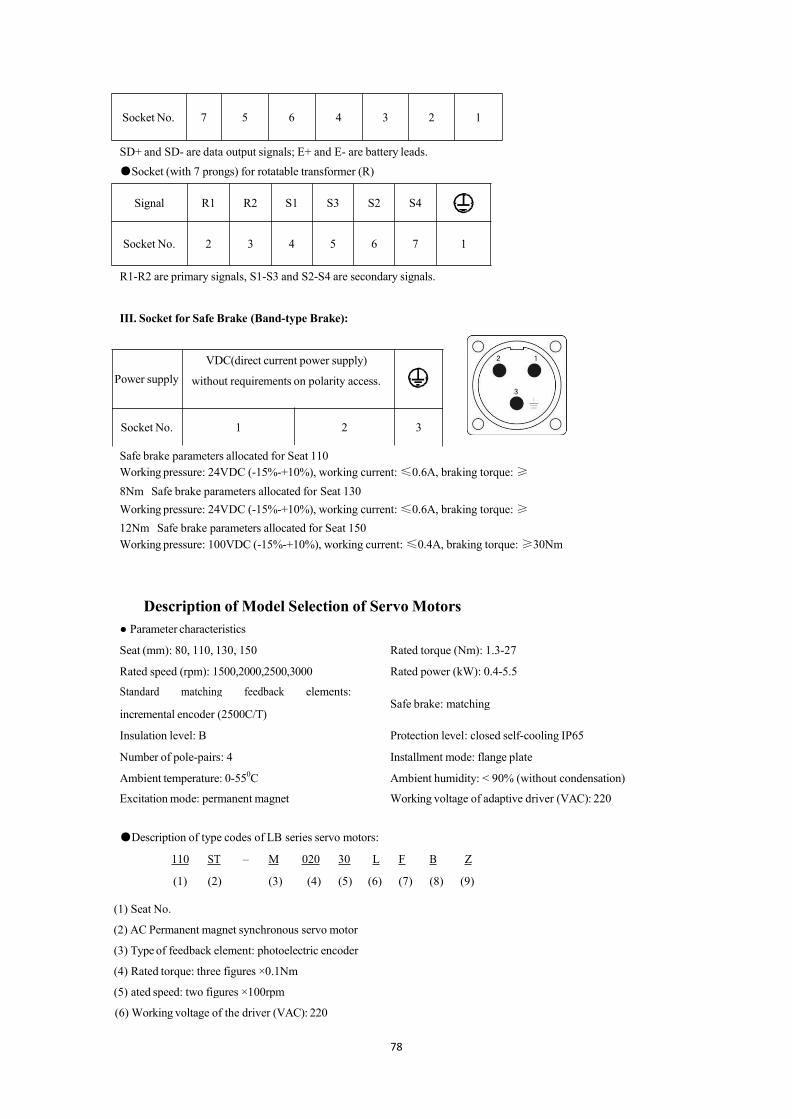
78
Socket No. 7 5 6 4 3 2 1
SD+ and SD- are data output signals; E+ and E- are battery leads.●Socket (with 7 prongs) for rotatable transformer (R)
Signal R1 R2 S1 S3 S2 S4
Socket No. 2 3 4 5 6 7 1
R1-R2 are primary signals, S1-S3 and S2-S4 are secondary signals.
III. Socket for Safe Brake (Band-type Brake):
Power supplyVDC(direct current power supply)
without requirements on polarity access.
Socket No. 1 2 3
Safe brake parameters allocated for Seat 110Working pressure: 24VDC (-15%-+10%), working current:≤0.6A, braking torque:≥8Nm Safe brake parameters allocated for Seat 130Working pressure: 24VDC (-15%-+10%), working current:≤0.6A, braking torque:≥12Nm Safe brake parameters allocated for Seat 150Working pressure: 100VDC (-15%-+10%), working current:≤0.4A, braking torque:≥30Nm
Description of Model Selection of ServoMotors● Parameter characteristics
Seat (mm): 80, 110, 130, 150 Rated torque (Nm): 1.3-27
Rated speed (rpm): 1500,2000,2500,3000 Rated power (kW): 0.4-5.5
Standard matching feedback elements:
incremental encoder (2500C/T)Safe brake: matching
Insulation level: B Protection level: closed self-cooling IP65
Number of pole-pairs: 4 Installment mode: flange plate
Ambient temperature: 0-550C Ambient humidity: < 90% (without condensation)
Excitationmode: permanent magnet Working voltage of adaptive driver (VAC): 220
●Description of type codes of LB series servo motors:
110 ST – M 020 30 L F B Z
(1) (2) (3) (4) (5) (6) (7) (8) (9)
(1) Seat No.
(2) AC Permanent magnet synchronous servo motor
(3) Typeof feedback element: photoelectric encoder
(4) Rated torque: three figures ×0.1Nm
(5) ated speed: two figures ×100rpm
(6) Working voltage of the driver (VAC): 220

79
(7) Standard matching: F-incremental encoder (2500 C/T), F1- wire saving incremental encoder (2500C/T).
(8) Medium inertia
(9) A safe brake has been installed.
Dimensions and TypeSelection Parameters of Servo Motors
● Seat 80
Type 80ST-M01330LF1B 80ST-M02430LF1B 80ST-M03330LF1B
Power 0.4 kW 0.75 kW 1.0 kW
Rated torque 1.3 Nm 2.4 Nm 3.3 Nm
Rated speed 3000 rpm 3000 rpm 3000 rpm
Rated current 2.6 A 4.2 A 4.2 A
Rotor inertia 0.74×10⁻⁴Kgm2 1.2×10⁻⁴Kgm2 1.58×10⁻⁴Kgm2
Maximum current 7.8 A 12.6 A 12.6 A
Maximum torque 3.9 Nm 7.2 Nm 9.9 Nm
Maximum radial andaxial forces
Fr≤200N
Fs≤50N

80
Seat 80:
-0.013 -0.03 -0.1
-0.013 -0.03 -0.1
-0.013 -0.03 -0.1
● Seat 11
Type110ST-M02030LFB
110ST-M04030LFB
110ST-M05030LFB
110ST-M06020LFB
110ST-M06030LFB
Power 0.6 kW 1.2 kW 1.5 kW 1.2 kW 1.6 kW
Rated torque 2.0 Nm 4.0 Nm 5.0 Nm 6.0 Nm 6.0 Nm
Rated speed 3000 rpm 3000 rpm 3000 rpm 2000 rpm 3000 rpm
Rated current 4.0A 5.0 A 6.0 A 6.0A 8.0A
Rotor inertia
0.425×10⁻³ 0.828×10⁻³ 0.915×10⁻³ 1.111×10⁻³ 1.111×10⁻³
Kgm2 Kgm2 Kgm2 Kgm2 Kgm2
(0.489×10⁻³ (0.892×10⁻³ (0.979×10⁻³ (1.175×10⁻³ (1.175×10⁻³
Kgm2) Kgm2) Kgm2) Kgm2) Kgm2)
Maximumcurrent
12.0 A 15.0 A 18.0 A 18.0A 24.0 A
Maximumtorque
6.0 Nm 12.0 Nm 15.0 Nm 18.0 Nm 18.0 Nm
Maximumradial and axialforces
Fr≤600N
Fs≤180N
yp A B L L1 d b t
0S 1 5 3 Φ1 6 15.
0S 1 5 3 Φ1 6 15.
0S 1 5 3 Φ1 6 15.

81
KeyA Key B Key B
Seat 110:
-
-0.013 -0.03 -0.1
● Seat 130Type 130ST-M04025LFB 130ST-M05020LFB 130ST-M05025LFB 130ST-M06025LFBPower 1.0 kW 1.0 kW 1.3 kW 1.5 kW
Rated torque 4.0 Nm 5.0 Nm 5.0 Nm 6.0 Nm
Rated speed 2500 rpm 2000 rpm 2500 rpm 2500 rpm
Rated current 4.0A 5.0A 5.0A 6.0A
Rotor inertia 1.101×10⁻³Kgm2 1.333×10⁻³Kgm2 1.333×10⁻³Kgm2 1.544×10⁻³Kgm2
-0.013 -0.03 -0.1
-0.013 -0.03 -0.1
-0.013 -0.03 -0.1
ype
A(m
A1(m
B(m
L(m
L1(m
L2(m d
(mb(m
t(m
10S 1 2 76 4 40 3 Φ10
60
15.0
10S 1 2 1 4 40 3 Φ10
60
15.0
10S 2 2 1 4 40 3 Φ10
60
15.0
10S2 2 1 4 40 3 Φ1 6 15.-
10S-
1 5 3 8 9 00 5 0
7 9 4

82
(1.268×10⁻³Kgm2) (1.50×10⁻³Kgm2) (1.50×10⁻³Kgm2) (1.711×10⁻³Kgm2)
Maximumcurrent 12.0 A 15.0 A 15.0 A 18.0 A
Maximum torque 12.0 Nm 15.0 Nm 15.0 Nm 18.0 Nm
Maximum radialand axial forces
Fr≤900N
Fs≤300N
KeyA Key B Key
Seat 130:

83
-0.013 -0.03 -0.1
-0.013 -0.03 -0.1
-0.013 -0.03 -0.1
● Seat 130
Type 130ST-M07720LFB 130ST-M07725LFB 130ST-M07730LFB 130ST-M10015LFB
Power 1.6 kW 2.0 kW 2.4 kW 1.5 kW
Rated torque 7.7 Nm 7.7 Nm 7.7 Nm 10Nm
Rated speed 2000 rpm 2500 rpm 3000 rpm 1500 rpm
Rated current 6.0A 7.5 9.0 6.0
Rotor inertia2.017×10-3Kgm2
(2.184×10⁻³Kgm2)
2.017×10⁻³Kgm2
(2.184×10⁻³Kgm2)
2.017×10⁻³Kgm2
(2.184×10⁻³Kgm2)
2.595×10⁻³Kgm2
(2.762×10⁻³Kgm2)
Maximumcurrent
18.0 A 20.7 A 27.0 A 18.0 A
Maximumtorque
23.1Nm 23.1 Nm 23.1 Nm 30.0 Nm
Maximumradial and axialforces
Fr≤900N
Fs≤300N
KeyA Key B Key C
Seat 130:
ype
A(m
A1(m
B(m
L(m
L1(m
L2(m
d(mm)
b (mm) t (mm)
130 16 20 8 50 4 5 Φ22 0 6 0 18.5 0
130T-
171
213
89
50 40
5 Φ22 0 6 0 18.5 0
130ST-
130 18 22 9 50 4 5 Φ2 0 6 0 18. 0

84
-0.013 -0.03 -0.1
-0.013 -0.03 -0.1
● Seat 130
Type 130ST-M10025LFB 130ST-M15015LFB 130ST-M15025LFB
Power 2.6 Kw 2.3 Kw 3.9 Kw
Rated torque 10.0 Nm 15.0 Nm 15.0 Nm
Rated speed 2500 rpm 1500 rpm 2500 rpm
Ratedcurrent
10.0A 9.5 A 17.0 A
Rotor inertia2.595×10-3Kgm2
(2.762×10⁻³Kgm2)
4.32×10⁻³Kgm2
(4.487×10⁻³Kgm2)
4.32×10⁻³Kgm2
(4.487×10⁻³Kgm2)
Maximumcurrent
30.0A 28.5 A 51.0 A
Maximumtorque
30.0 Nm 45.0 Nm 45.0 Nm
KeyA Key B Key C
ype
A(m
A1
B(m
L(m
L1(m
L2(m d (mm)
b(mm) t (mm)
130
19 23 11 5 40 5 Φ22 0 6 0 18.5 0
ST-
130ST- 5 7 2 0130ST-
130 21 26 13 5 40 5 Φ2 0 6 0 18. 0

85
Seat 130:
Type A(mm)
A1(mm)
B(mm)
L(mm)
L1(mm)
L2(mm)
d (mm) b (mm) t (mm)
130ST-M10025
LFB219 261 136 50 40 5 Φ22 0
-0.013 6 0-0.03
18.5 0
-0.1
130ST-M15015LFB
267 309 184 50 40 5 Φ22 0
-0.013 6 0-0.03
18.5 0
-0.1130ST-M15025LFB
● Seat 150
Type 150ST-M15025LFB 150ST-M18020LFB
Power 3.8 Kw 3.6 Kw
Rated torque 15.0 Nm 18.0 Nm
Rated speed 2500 rpm 2000 rpm
Rated current 16.5 A 16.5 A

86
Rotor inertia6.15×10-3Kgm2
(6.75×10⁻³Kgm2)
6.33×10⁻³Kgm2
(6.93×10⁻³Kgm2)
Maximumcurrent 49.5 A 49.5 A
Maximum torque 45.0 Nm 54.0 Nm
● Seat 150
Type 150ST-M23020LFB 150ST-M27020LFB
Power 4.7 Kw 5.5 Kw
Rated torque 23.0 Nm 27.0 Nm
Rated speed 2000 rpm 2000 rpm
Rated current 20.5 A 20.5 A
Rotor inertia8.94×10-3Kgm2
(9.54×10⁻³Kgm2)
11.19×10⁻³Kgm2
(11.79×10⁻³Kgm2)
Maximumcurrent 61.5 A 61.5 A
Maximum torque 69.0 Nm 81.0 Nm
KeyA Key B Key C

87
Seat 150
Type A(mm)
A1(mm)
L(mm)
L1(mm)
L2(mm) d (mm) b (mm) t (mm)
150ST-M15025LFB 231 293 72 60(Key B)55(Key C) 5 Φ28 0
-0.013 8 0-0.03
24 0
-0.1
150ST-M18020LFB 250 312 72 60(Key B)55(Key C) 5 Φ28 0
-0.013 8 0-0.03
24 0
-0.1
150ST-M23020LFB 280 342 72 60(Key B)55(Key C) 5 Φ28 0
-0.013 8 0-0.03
24 0
-0.1
150ST-M27020LFB 306 368 72 60(Key B)55(Key C) 5 Φ28 0
-0.013 8 0-0.03
24 0
-0.1
●Curve diagram of torque and speed:LB andHB series
Mmax of LB and LBB series servo motor is equal to 3Mn; Mmax output status is the short time work of the
servo motor. Please refer to the output capacity of the matching driver before use.

88
Appendix 1
Siemens NC system matched for MG -1000 Series Drivers(Tomatch Siemens 802S/801/802S)
1. Setting requirements for driver parameters
ParameterNo. ParameterName Unit ParameterRange Default5 Speed ratio gain Hz 50-2000 15036 filter factor of
command pulsesignal
% 0-3 1
Note:● When a Siemens NC system is matched for the driver, PA36 should be equal to 1 and PA37 to 0;
otherwise repeated position precision will be affected.
● Where reset deviations are not uniform, appropriately increase Parameter 5 of the driver.
● Pins 36 and 9 of the CN1 interface port must be connected with the shielding layer and metal casing of the
system; otherwise reset precision will be affected.
2. Setting requirements for Siemens system parameters
ParameterNo. ParameterName Required value34040 Search for Z-pulse speed 500-2000

89
Appendix 2
Wiring Diagram forMG-1000B driver and Siemens 801/802S
与西门子 801、802S接线图 Wiring diagram of the driver and Siemens and 801/802S
西门子 801(×4接口)Siemens 801(x4 interfaces)
西门子 801(×20接口)Siemens 801(x20 interfaces)
Z轴 Z axis X轴 X axis
西门子×4插头金属壳 Siemens x 4 plug metal casing
注:驱动器端 36和 9脚一定要和屏蔽层和系统的金属壳相联。Note: Pins 36 and 9 at the driver side must be connected with the
shielding layer and the metal casing of the system.
驱动器 Driver 屏蔽层 Shielding layer
编码器信号地 Encoder signal groundwire 外接+24V电源 External connection to +24Vpower supply
外接 0V电源 External connection to 0V power supply

90
Appendix 3
数控系统侧×7,×3 NC system side x7, x3
连接电缆 Cable 驱动器
侧 CN1Driver side CN1 驱动
器 Driver
X给定+ X preset+
X给定- X preset-
原始信号 OB+ Original signal OB+
原始信号 OB- Original signal OB-
原始信号 OA+ Original signal OA+
原始信号OA- Original signal OA-
9、36脚要短接 Pin 9 and 36 should be short circuited.
驱动器参数调整:Driver parameter adjustment

91
PA-4 调整为 1、PA-22调整为 1、PA-43按需要调整 Adjust PA-4 to 1, PA-22 to 1 and adjust PA-43as required
PA-40 调整为 1、PA-41调整为 1。 Adjust PA-40 to 1 and PA-41 to 1.
西门子 802C系统参数调整:西门子 802C系统的参数 30130要改为“1”。
Siemens 802C system parameter adjustment: Parameter 30130 of Siemens 802C system should be changed to―1‖.
按以上接线图接好线后,先调整好以上参数,在系统上电,驱动器上电,打开驱动器使能,系统保持零速状态,调整驱动器 AU-Spd
(模拟量速度零偏自动调整)。调整方法为:在驱动器的第一层菜单界面找到AU,再按 enter一次,显示AU-Spd,再按住 enter
不放,并保持3秒,就会显示 FINISH(成功),最后保村参数即可。
After wiring as per the above the wiring diagram, first adjust the above parameters, electrify the system and the driver, open the driver
enable, keep the system in zero speed state, and adjust the AU-Spd of the driver (automatic adjustment of speed bias of analog value). The
adjustment method thereof: Find AU in the first menu interface of the driver and press enter once again to display AU-Spd. Then press
down enter for 3 seconds and FINISH (success) will be displayed. Finally store the parameters.

92
Appendix 4
GSK928TE(×5)X轴DB针插头 GSK928TE(x5) X axis DB pin plug
驱动器(X轴)Driver (X axis)
红 Red
红黑 Red & black 橙
黑 Orange& black
黄黑 Yellow& black
绿 Green
绿白 Green & white
蓝 Blue
蓝白 Blue& white
黑 Black
金属壳地 metal casing ground wire GSK928TE
(×5)Z轴 GSK928TE (x5) Z axis
驱动器(Z轴) Driver (Z axis)
金属壳地metal casing ground wire

93
GSK928TE(×4)DB孔插头 GSK928TE(x4) DB hole plug
X轴零位 X axis zero position
Z轴零位 Z axis zero position
刀架正转信号 Toolholder forward rotation signal
+24V电源 +24Vpower supply
1号刀 Tool 1
3 号刀 Tool 3
刀架正转信号 Toolholder reverse rotation signal
2号刀 Tool 2
4 号刀 Tool 4
机壳地 Driver housing ground wire
线上加套管标识!Marks for adding a bushing on a wire!

94
Appendix 5
GSK980系列(X,Z轴)GSK980 series ( X axis and Z axis)
驱动器 Driver

95
Appendix 6
Wiring Diagram ofMG-1000 Series of Drivers with KNDNC System
注 1 Note 1
注 2 Note 1
数控系统侧 NC system side
驱动器侧 Driver side 信号 名
称 Signal Name 管脚
Pin
金属壳接地 Metal casing grounded

96
Appendix 7
新代数控系统 SYNTECNC system
15芯针 DB插头 15-core DB plug 驱
动器 Driver
A、B正交脉冲 A&B orthogonal pulses
使用A/B正交脉冲信号,系统各轴的分辨率应调整为:2500,然后再 4倍频
A/B orthogonal pulse signal should be used. The resolution of all axes of the system should be adjusted to 2500 and then quadruple
frequency.
一定要使用双绞屏蔽线,屏蔽层两端一定要接地。
Twisted-pair shielding wire must be used. Both ends of the shielding layer must be grounded.
使能继电器 Enable relay
24V地 24V ground wire
金属壳地Metal casing ground wire

97
华中 21/22系统 Huazhong21/22 system
XS10 接口 XS10 interface
Appendix 8
XS11接口 XS11 interface
输入 Input
XS20接口 XS20 interface
输出 Output
24V地 24Vground wire
使能 Enable
驱动器 Driver
位置控制方式接线图 WiringDiagram for Position Control Mode
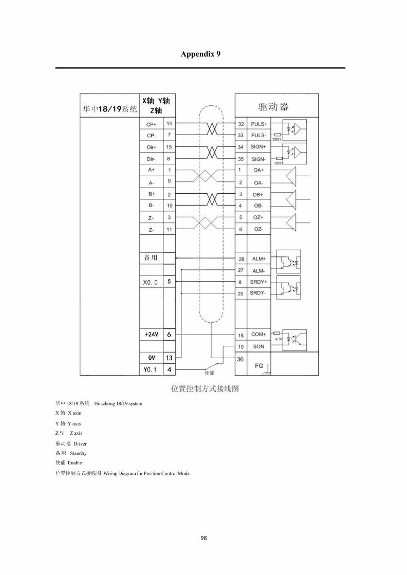
98
Appendix 9
华中 18/19系统 Huazhong 18/19 system
X轴 X axis
Y轴 Y axis
Z轴 Z axis
驱动器 Driver
备用 Standby
使能 Enable
位置控制方式接线图 WiringDiagram for Position Control Mode

10
Appendix 10
This prod uct and the manual are only used fo r gen eral industr ia l purposes. Where this
product i s used with equipment directly relativ e to l ife and safety, su ch as medical t
reatment , aviat ion, aero sp ace, and nuclear po wer, e tc. Please contact the manu facturer .
This manual shall not be reprinted or copied in part or in whole without the permission of the company. This product
is subject to change without further notice due to constant renovation.

100