Embed Size (px)
Citation preview
1
Atomic Layer Deposition System Design
Meng Shi, Xuan Gao
Department of Physics, Case Western Reserve University, Cleveland, Ohio 44106-7079
Undergraduate Senior Project
2
Abstract
In the process of nanofabrication, deposition techniques are always extremely
important. Factors such as large area, conformity and reproducibility can affect the end
results dramatically. Using the technique of atomic layer deposition (ALD), large
quantities of conformal film can be coated onto a wide array of substrate material with
excellent repeatability. This technique also has the benefit of simple and accurate
control over deposition thickness on the order of angstroms, allowing alternating
monolayer stacks of particles to bond to a surface. Commercial products are available
but extremely expensive. However, the theoretical setup for ALD is not that
complicated. Therefore, the goal of this project is to design and build a working ALD
system with focus on Al2O3 film deposition that costs a fraction of the retail price. In the
end, the system is still incomplete requiring a few more key components before being
operational.
3
Introduction
As technology continues to push the limits of electronics, demand for smaller
and smaller devices increase. At the nanoscale, it becomes extremely important to be
able to fabricate films of material with precise thicknesses and conformal coverage of
the target surface.1-3 Development and implementation of atomic layer deposition
(ALD) systems aim to accomplish these specifications.
ALD systems have evolved and advanced greatly in the last decade; to the point
where several companies have arisen solely to manufacture them. However, the theory
behind ALD is not very complicated, and therefore it is possible to design and build a
custom system without relying on the manufacturing companies. Motivation for
building a system from scratch is due to the high cost of purchasing a complete system.3
It is far more economical to construct due to the simple application needs such a system
will provide.
My project will involve studying past research on ALD systems with a focus on
Al2O3, which is cheap and an insulator, with the intention of being deposited across
other devices for testing. After research, a design system will be created to minimize
costs and fit with available equipment in the lab. Other parts will be purchased and
4
assembled. The final goal is to calibrate and test the system, with importance placed on
attempting to produce similar results found in the literature.
Thin Films
Thin films are, by definition, a layer of material on the order of nanometers
upwards to several microns in thickness. Depending on the material, application of thin
films ranges from reflective coatings to intricate electronic interfaces. Because of the
many uses of thin films, the techniques of deposition are very important. In general,
there are two types of thin film deposition, chemical and physical.
In chemical deposition, a precursor liquid or gas is introduced onto the surface of
interest, where then a reaction occurs bonding the precursor and the surface. This type
of deposition tends to produce conformal films, or where the thickness of the film is
uniform irrelevant of how rough the surface is. Common types of chemical deposition
include chemical vapor deposition (CVD) and plating.
In contrast, physical deposition makes use of mechanical and thermodynamic
interactions to produce thin films that are not actively bonded to the surface. In this
technique, the film material is energized to vaporization and then allowed to travel to
the cooler target surface where a solid film layer forms. Normally, physical deposition
5
is performed in vacuum to reduce collisions and allow the particles to travel as fast as
possible to the film site. This tends to create directional deposition, where the surfaces
perpendicular to the flow of particles have thicker films than parallel ones. Thermal
evaporation, sputtering, and pulsed laser deposition are some of the common types of
physical deposition.
Atomic Layer Deposition
Atomic layer deposition is a type of chemical deposition, implying that the film
adheres strongly to the surface while maintaining conformity. ALD utilizes two
alternating sequential (ABAB) gas exposures with a purging gas in between to ensure
the two reactants do not mix. If we specify that the reactants are labeled as A and B with
the purging gas as C, then a complete cycle of deposition is simply the introduction of
these gasses in the order ACBC.4,5 Each of these reactant gases are required to be self-
limiting, in the sense that after an initial reaction to the surface, no further reactions will
occur between the reactant with itself and/or any products produced. After a complete
cycle, the surface must also be reset to the original conditions to allow continued
deposition. Because the deposition can be terminated successfully after a single layer of
6
deposition, it is able to produce monolayers of film as well as controlling the thickness
of films based on the thickness of the monolayer.
ALD has many other advantages, such as large area uniformity. Since the
deposition is a chemical reaction and self-limiting, large surface areas can be covered
using this technique without much difficulty. This system has the benefit of being
highly reproducible, and follows naturally from the requirement of needing many
repeated cycles to build a thicker film. The temperature ranges for these depositions are
also fairly low, ranging from 1500C to 4000C.
ALD for Al2O3
In production of Al2O3 thin films, reactant A is Trimethylaluminium (TMA),
reactant B is water vapor (H2O) and the purging gas C is nitrogen (N2). When TMA is
initially introduced to the deposition site, the reaction that occurs is
Al(CH3)3 + SiOH → SiOAl(CH3)2 + CH4 (1)
where the substrate surface is made of silicon (Si). The substrate itself is covered
in hydroxyl groups that come from the absorption of water vapor present in the air.
After purging the system with nitrogen, the next reactant is introduced. The second
reaction with water vapor is governed by
2H2O + SiOAl(CH3)2 → SiOAl(OH)2 + 2CH4 (2)

7
After this reaction, the surface of the film is primed for a new cycle of ALD due
to the presence of hydroxyl groups. The byproduct of both of these reactions is methane
(CH4) which does not react with either film layers, and therefore carried out of the
system during the next nitrogen purge.
At this point, the cycle is complete and a single monolayer of Al2O3 is deposited
on the silicon substrate. Continuing the procedure to deposit a thicker film simply
requires restarting the cycle with TMA and so forth. The reactions that govern further
growth are
Al(CH3)3 + Al-OH → Al-O-Al(CH3)2 + CH4 (3)
2H2O + Al-O-Al(CH3)2 → Al-O-Al(OH)2 + 2CH4 (4)
The thickness of a single layer of Al2O3 is ~1.07Å and therefore also the thickness
control of the system, allowing any multiple of this thickness to be theoretically
produced. The crystal structure is shown in Figure 1, with a detailed 3D view that can
be found at the site found under reference 6.
Figure 1: 2D impression of the 3D Al2O3 crystal structure
8
Design
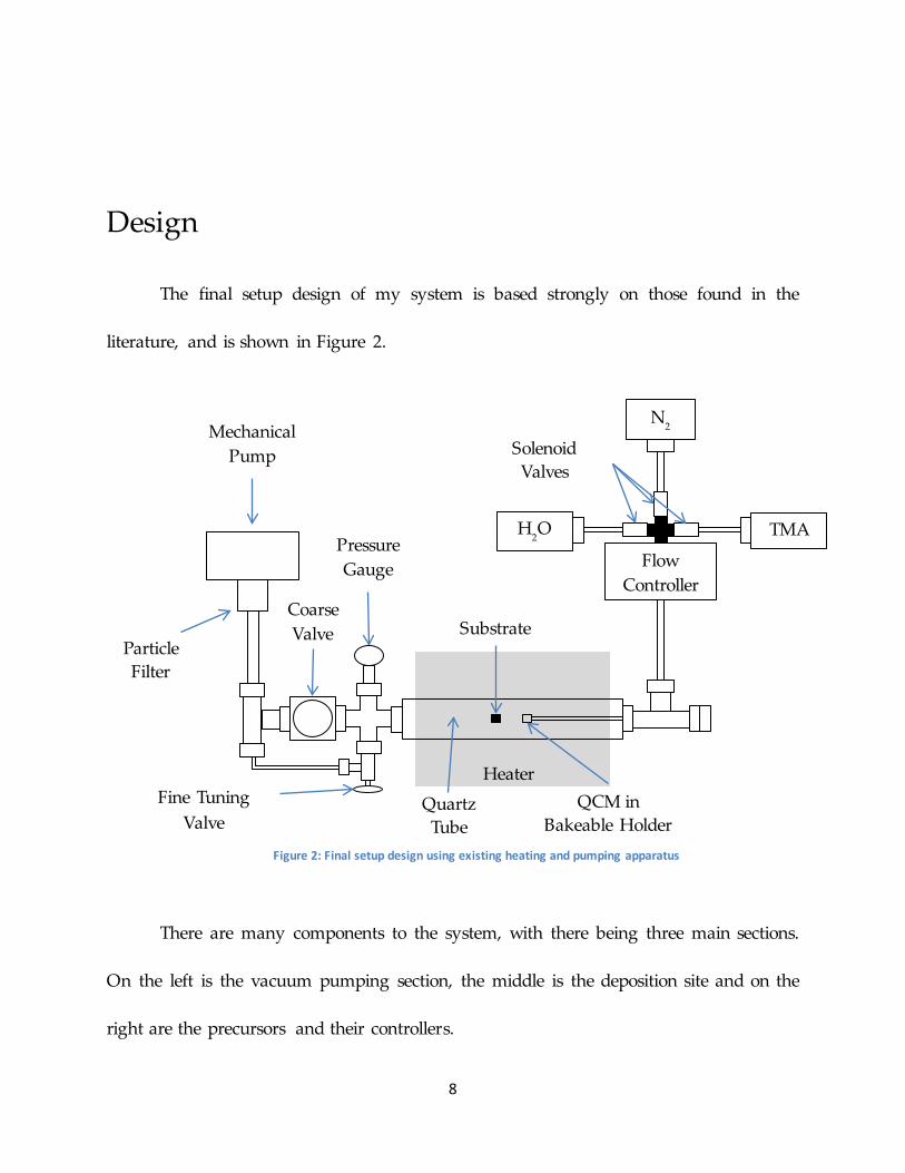
The final setup design of my system is based strongly on those found in the
literature, and is shown in Figure 2.
There are many components to the system, with there being three main sections.
On the left is the vacuum pumping section, the middle is the deposition site and on the
right are the precursors and their controllers.
Flow Controller
Mechanical Pump
Pressure Gauge
Heater
Quartz Tube
QCM in Bakeable Holder
Substrate
N2
TMA H2O
Particle Filter
Coarse Valve
Fine Tuning Valve
Solenoid Valves
Figure 2: Final setup design using existing heating and pumping apparatus
9
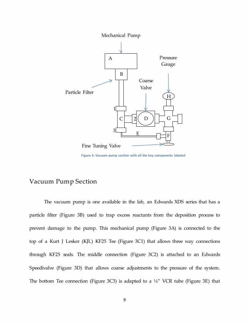
Vacuum Pump Section
The vacuum pump is one available in the lab, an Edwards XDS series that has a
particle filter (Figure 3B) used to trap excess reactants from the deposition process to
prevent damage to the pump. This mechanical pump (Figure 3A) is connected to the
top of a Kurt J Lesker (KJL) KF25 Tee (Figure 3C1) that allows three way connections
through KF25 seals. The middle connection (Figure 3C2) is attached to an Edwards
Speedivalve (Figure 3D) that allows coarse adjustments to the pressure of the system.
The bottom Tee connection (Figure 3C3) is adapted to a ¼” VCR tube (Figure 3E) that
Mechanical Pump
Particle Filter
Coarse Valve
Fine Tuning Valve
Pressure Gauge
Figure 3: Vacuum pump section with all the key components labeled
A
B
C
1
2
3
D G
E F
H
10
attaches to a Swagelok metering valve (Figure 3F) and used as a fine tuning control of
the system pressure. These two valves are attached to a KLJ KF25 Cross (Figure 3G) that
connects to a manometer (Figure 3H) on one end and the rest of the system on the other
end. The manometer is a KJL model, and is used to measure the pressure within the
system and relay the information to a computer station. When a precise pressure is
required, the coarse valve is first adjusted to be approximately the desired pressure, and
then the fine tuning valve is adjusted to give us an exact pressure value. The deposition
site will be maintained at a pressure of 0.1 Torr.
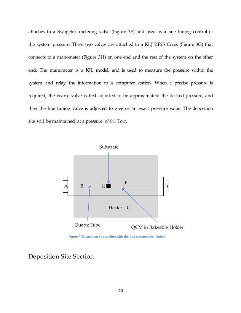
Deposition Site Section
Heater
Quartz Tube QCM in Bakeable Holder
Substrate
A B
C
D E F
Figure 4: Deposition site section with the key components labeled

11
Connecting from the vacuum pump section is a MKS KF25 to vacuum tube
compression fitting (Figure 4A) that seals the quartz tube (Figure 4B) used as the
deposition site. The quartz tube is housed within a heater (Figure 4C) that raises the
temperature to 1770C, the deposition temperature. The other end of the quartz tube is a
MKS vacuum compression fitting to KF40 adapter (Figure 4AD) to connect to the
precursors/controllers section. Within the quartz tube, the sample substrate (Figure 4E)
is placed, along with the quartz crystal microbalance (QCM) (Figure 4F). The sample
and QCM are loaded into the quartz tube by removing the compression seal on the
precursors/controllers section side.
The QCM is a device that measures changes in frequency that can be determined
through changes in mass using Saeurbrey’s equation. These changes in frequency can
then be correlated to changes in thickness confirmed through other techniques, such as
Ellipsometry. By placing the QCM very close to the substrate, we can approximate the
deposition rate by measuring the same rate on the surface of the QCM.
12
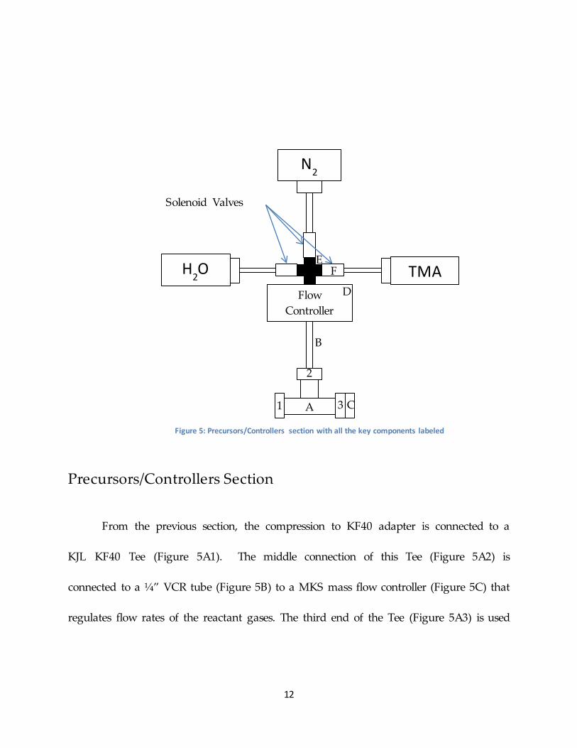
Precursors/Controllers Section
From the previous section, the compression to KF40 adapter is connected to a
KJL KF40 Tee (Figure 5A1). The middle connection of this Tee (Figure 5A2) is
connected to a ¼” VCR tube (Figure 5B) to a MKS mass flow controller (Figure 5C) that
regulates flow rates of the reactant gases. The third end of the Tee (Figure 5A3) is used
Flow Controller
N2
TMA H2O
Solenoid Valves
A 1
2
3 C
D
B
E F
Figure 5: Precursors/Controllers section with all the key components labeled
13
to connect the backend of the QCM (Figure 5D). It contains the feed through that allows
measuring of the crystal held within the quartz tube.
The mass flow controller is connected to a Swagelok union (Figure 5E) that
allows the three gases to be regulated by the same controller. Each of the three union
connections will be attached a Swagelok needle valve (Figure 5F). The needle valve is
used to manually control the amount of gas flow into the system while ensuring no
liquid reactant enters the system. The needle valves also ensure different pressures on
either side of the valve. On the reactant side, the pressure will quickly raise to that of its
vapor pressure, ~20 Torr for water and ~8.7 Torr for the TMA.
Each of the needle valves is connected to a Swagelok electropneumatic actuating
solenoid ball valves (Figure 5F). These are valves designed to only activate in the
presence of an electric current, which opens the valve by activating a compressed air
line. This seemingly roundabout method is designed to account for unforeseen power
outages. In the case of a power outage, the loss of electric current will deactivate the
compressed air which in turn closes the ball valve. This effect is apparently not
achievable with electrical valves alone. From these solenoid valves a VCR tube is fitted
that then connects to the gas containers. Each of the containers will possess their own
ball valve or regulator to allow manual shut off of the gases.

14
Safety
The issue of safety in this project is important due to the dangers of the TMA
precursor. The MSDS for TMA lists that the chemical can cause severe burns if physical
contact is made. The chemical is also highly flammable, reacts violently with water, and
can spontaneously ignite in air. To ensure safety, the entire system will first be leak
tested with helium. In this process helium is allowed to flow through the entire system,
and a mass spectrometer is used to detect if there is any leakage anywhere. The entire
system will also be housed within a walk in fume hood, to help ventilate out the gas in
case of a leak. Beyond these safety measures, the handling of this chemical in this
project should not require anything more. Goggles, gloves, and lab coats should also be
used to provide extra protection.
Current Progress
The system is currently ~80-90% complete. Due to communication issues with
one company, the QCM device still has not been purchased. The solenoid valves have
only recently arrived, and was discovered that they are several pounds in weight, and
since the quartz tube will be approximately a foot off the table, a stand needs to be
made to support the devices. Compressed air is available within the fume hood;
however, it must be split in some way to provide air to each of the three solenoid

15
valves. These valves also require electrical inputs that are controllable by a computer for
automation. The following are images of the setup equipment that are currently
available. Some of the parts are not connected together due to lack of space. Once the
supports are placed, room will be available to make all of the connections.
Figure 6: Overview of the setup area with the three different sections in separate pieces
16
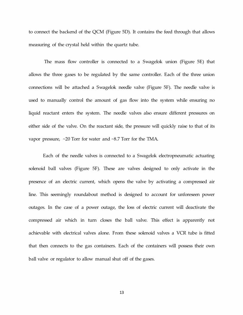
Figure 7: Precursors/Controllers section containing the solenoid valves needed to allow automation
17
Results in Literature
While the system is incomplete and therefore no data can be collected ourselves,
it is useful to understand the kinds of results we expect and wish to find.
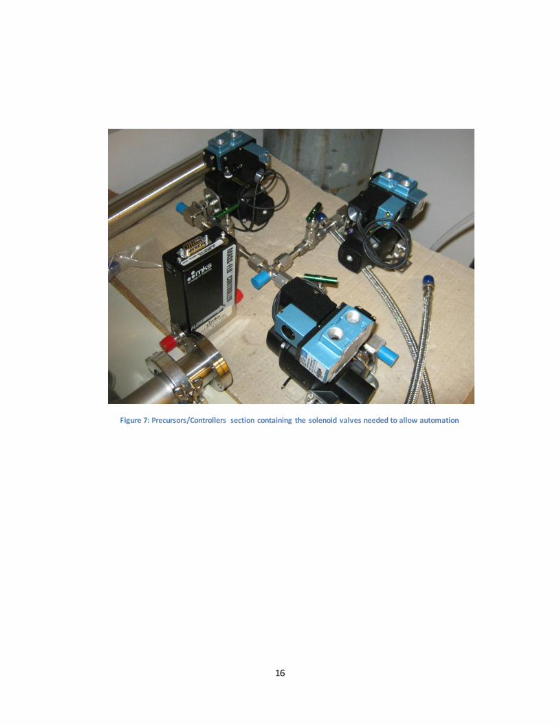
In Figure 8, the Al2O3 film thickness is measured as a function of time. This is also
correlated to the mass deposited as measured by the QCM used in their system. The
Figure 8: Average Al2O3 thickness in a single cycle showing most of the film thickness arises from the first reactant TMA
Average Al2O3 Thickness in a Single Cycle
18
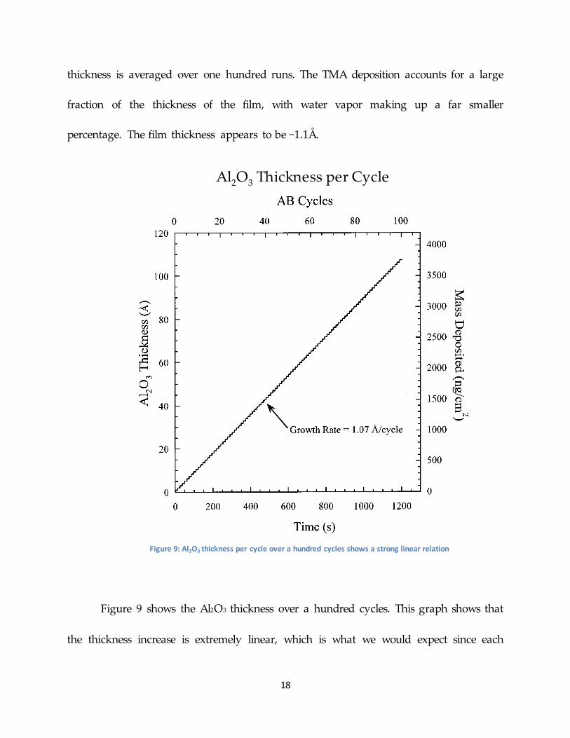
thickness is averaged over one hundred runs. The TMA deposition accounts for a large
fraction of the thickness of the film, with water vapor making up a far smaller
percentage. The film thickness appears to be ~1.1Å.
Figure 9 shows the Al2O3 thickness over a hundred cycles. This graph shows that
the thickness increase is extremely linear, which is what we would expect since each
Al2O3 Thickness per Cycle
Figure 9: Al2O3 thickness per cycle over a hundred cycles shows a strong linear relation
19
cycle should produce 1.07Å of film. The discrete steps observed in the data show that
the film is being deposited in layers. These observations reinforce our knowledge that a
termination of the deposition process after any complete cycle will leave a conformal
film whose thickness is easily determined. The slope of this line is where the estimation
of the thickness control for the system originates.
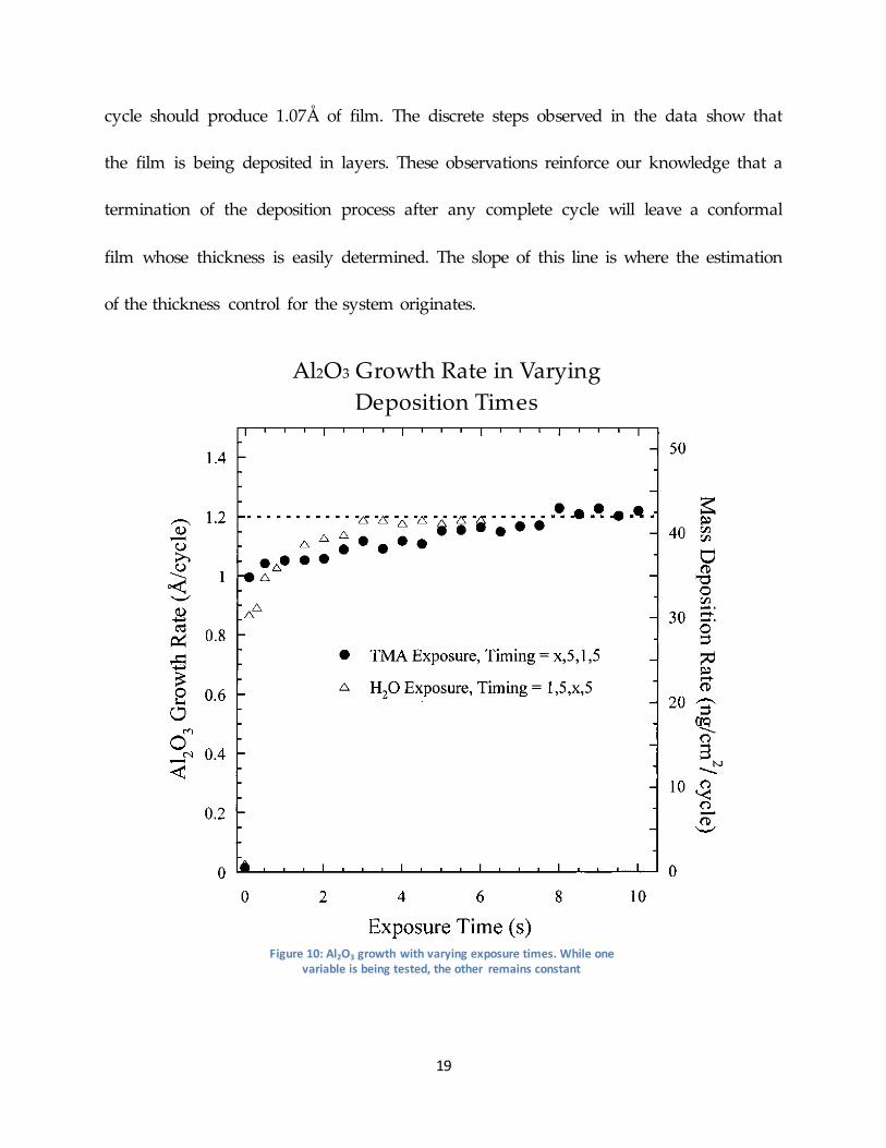
Al2O3 Growth Rate in Varying Deposition Times
Figure 10: Al2O3 growth with varying exposure times. While one variable is being tested, the other remains constant
20
Figure 10 analyses what happens to the Al2O3 growth rate when the deposition
times of the TMA and H2O are varied away from their starting values of 1 second.
While one exposure time is being varied, the other is being held constant at the original
1 second. What is found is that under both circumstances, the growth rate saturates at
~1.2Å/cycle. The saturation occurs after 3 seconds for varying H2O times and after 8
seconds for varying TMA times. These results are found to be consistent with previous
works and ex situ ellipsometry measurements.
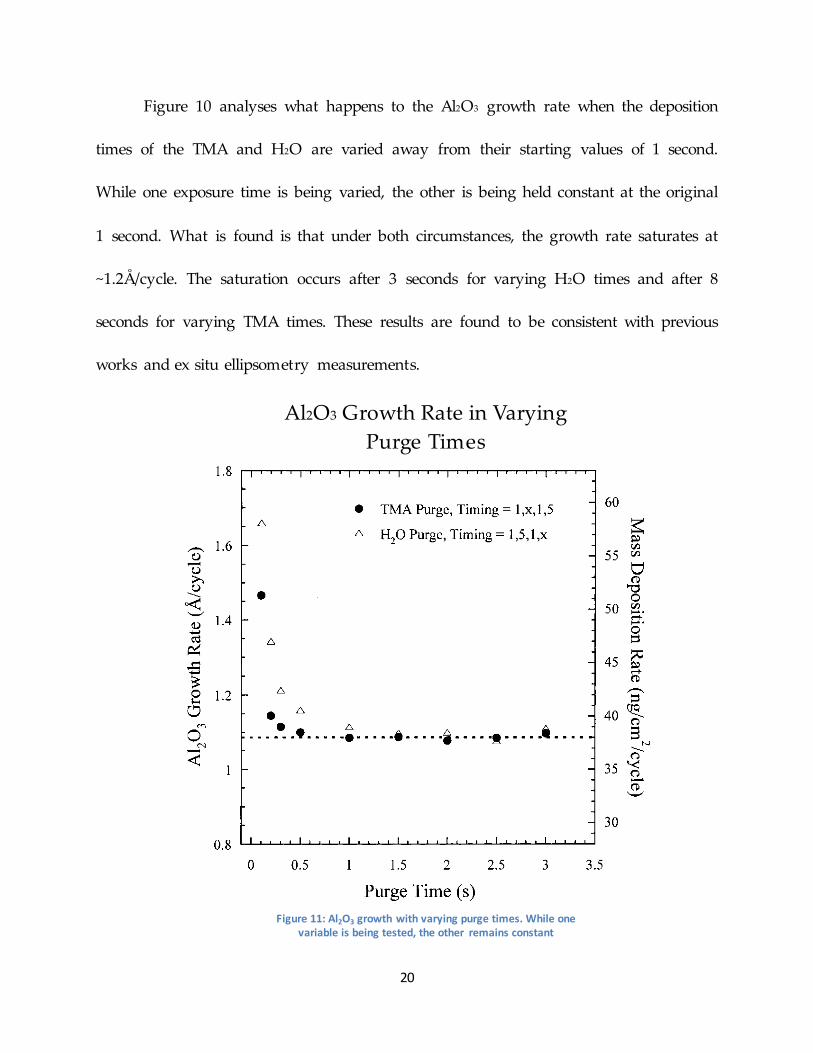
Al2O3 Growth Rate in Varying Purge Times
Figure 11: Al2O3 growth with varying purge times. While one variable is being tested, the other remains constant

21
In Figure 11, Al2O3 growth rates are measured while purge times after reactant
exposure are varied. As in the previous test, while one time was being varied, the other
time remained constant at its original value, in this case 5 seconds. During these
experiments the exposure times of the precursors remained constant at 1 second. It is
found that purge times less than 1 second for H2O and 0.5 seconds for TMA causes large
spikes in the Al2O3 growth rate. This is attributed to the fact that the purge times are
insufficiently long enough to remove all particulates of the previous reactant before the
next reactant is introduced. The mixing of the precursors causes a reaction that
produces CVD, which his undesirable. To ensure this does not occur, purge times
greater than 1 and 0.5 seconds for H2O and TMA, respectively, are required.
In a separate test, this same ALD growth was performed where only the sample
substrate is heated and not the entire deposition site, it was determined that a purge
time greater than 15 seconds was needed to avoid the CVD effect. This is an important
observation, and luckily our system by default causes the entire deposition site to be
heated.

22
Future Work
The first thing that must be accomplished is the completion of the set up with the
supports and secondary equipment. Once this has been accomplished, we would like to
reproduce these results. Having done that, the implementation of this technique in
other work being done in the lab will become viable.
Because I was unable to finish my project as originally planned, I will also need
to prepare detailed information about the parts purchased, the system design, and all
the things I have learned and observed for my successor. Hopefully my notes will allow
him/her to finish what is left of this project quickly and easily.
Acknowledgements
I would like to acknowledge my advisor, Professor Xuan Gao, for providing
guidance and supporting my work on this project. It has been an immense honor to
have been able to work in his lab. I would also like to thank graduate student Dong
Liang who helped in refining the setup and finding the parts needed. His help in
navigating through the commercial maze of sites and information was extremely
helpful and valuable
23
References
1. P.K. Chatterjee and G. B. Graydon, IEEE Tans. Syst., I (1993) 7.
2. A. Masaki, IEEE Circ. Dev., 8 (1992) 18.
3. Cambridge Nanotech 2003
4. C.H.L. Goodman and M.V. Pessa, J. Apply. Phys., 60 (1986) R65.
5. T. Suntola, Thin Solid Films, 216 (1992) 84.
6. http://wwwchem.uwimona.edu.jm:1104/courses/corundumJ.html
7. J.W. Elam, M.D. Groner, S.M. George, Rev. Sci. Instr., 8 (2002) 73

24