Embed Size (px)
Citation preview
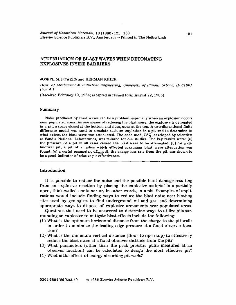
Journal of Hazardous Materials, 13 (1986) 121-133 Elsevier Science Publishers B.V., Amsterdam - Printed in The Netherlands
121
ATTENUATION OF BLAST WAVES WHEN DETONATING EXPLOSIVES INSIDE BARRIERS
JOSEPH M. POWERS and HERMAN KRIER
Dept. of Mechanical & Industrial Engineering, University of Illinois, Urbana, IL 61801 (U.S.A.)
(Received February 19,1985; accepted in revised form August 22,1985)
Summary
Noise produced by blast waves can be a problem, especially when an explosion occurs near populated areas. As one means of reducing the blast noise, the explosive is detonated in a pit, a space closed at the bottom and sides, open at the top. A two-dimentional finite difference model was used to simulate such an explosion in a pit and to determine to what extent the blast wave was attenuated. The code used, CSQ, developed by scientists at Sandia National Laboratories, was tailored for our studies. The key results were: (a) the presence of a pit in all cases caused the blast wave to be attenuated; (b) for a cy- lindrical pit, a pit of a radius which effected maximum blast wave attenuation was found; (c) a useful parameter, dE,-&dt, the energy loss rate from the pit, was shown to be a good indicator of relative pit effectiveness.
Introduction
It is possible to reduce the noise and the possible blast damage resulting from an explosive reaction by placing the explosive material in a partially open, thick-walled container or, in other words, in a pit. Examples of appli- cations would include finding ways to reduce the blast noise near blasting sites used by geologists to find underground oil and gas, and determining appropriate ways to dispose of explosive armaments near populated areas.
Questions that need to be answered to determine ways to utilize pits sur- rounding an explosive to mitigate blast effects include the following: (1) What is the optimum horizontal distance from the charge to the pit walls
in order to minimize the leading edge pressure at a fixed observer loca- tion?
(2) What is the minimum vertical distance (floor to open top) to effectively reduce the blast noise at a fixed observer distance from the pit?
(3) What parameters (other than the peak pressure pulse measured at an observer location) can be calculated to design the most effective pit?
(4) What is the effect of energy-absorbing pit walls?
0304-3894/86/$03.50 0 1986 Elsevier Science Publishers B.V.
122
In this study we modelled the dynamic processes in and surrounding the pit by providing the solution to the time-dependent equations which con- serve mass, momentum, and energy of the gases produced by the explosive as well as the air inside the pit. Clearly, a minimum of two independent space dimensions is required. The blast produces shocks and strong compres- sion waves which propagate at supersonic speeds relative to the undisturbed air. The waves can move several kilometers per second. A km/s is also one mm/MS, and therefore it follows that the flow variables pressure, density, and energy need to be calculated at microsecond (1W6 s) time levels since changes in the flow variables occur over distances in the scale of millimeters or less.
The code CSQ, developed by scientists at Sandia National Laboratories, documented in a Sandia Technical Report [ 11, was used to model the prob- lem.
Governing equations
The two-dimensional, time-dependent, Lagrangian form of the governing equations of conservation of mass, momentum, and energy in cylindrical coordinates used are
Conservation of mass
aP -=- at p [
1 a(m) + av, r ar az 1
Conservation of momenta
af+ -a aurz (urr + Qrr) - - -
lJtr - fJe0
7-Z Tz=ar a2 r
a~, -a ah or2 2: pat =az fuzz + Qzz) - - - -
ar r
Conservation 0 f energy
aE -=-((P+G) ;( ;, at
(2.1)
(2.2a)
(2.3)
Here p represents density; t, time; r, the radial coordinate; Ur, the particle velocity in the x direction; z, the height coordinate; u,, the particle velocity in the z direction; alar and a/i&z, the partial derivatives with respect to the Lagrangian coordinates, r and z, respectively; 8 /at, the partial derivative with respect to time; (I, the stress tensor; Q, the artificialviscosity; P, the material pressure; and E, the specific material energy. These equations must be sup- plemented with an equation of state to have a determinate system.
123
Application of CSQ to the explosion-in-pit problem
As stated earlier, the program CSQ has been used to model the detonation of a high explosive surrounded by air in a cylindrical pit open to the atmo- sphere. Figure l,? ,the half-section view of a right circular cylinder, shows the ‘features and gridding of a typical configuration. By placing the explosives at the center of the pit, it is possible to reduce the problem from three dimen- sions to two, with symmetry in the angular (13 ) direction.
80 ccl
c” ‘S C E ,n
Fig. 1. Descriptions of the grid used by CSQ to model cases of varying charge mass, am- bient temperature, and pit radius.
Two types of boundary conditions were employed, reflecting and trans- mitting. In all cases considered in this study, pit walls were treated as per- fectly reflecting boundaries. Velocities at reflecting boundaries were defined to be zero. At transmitting boundaries, mass, momentum, and energy fluxes were permitted. CSQ used appropriate extrapolation schemes to determine the magnitudes of the fluxes.
CSQ is a two-dimensional (planar or cylindrical) hydrodynamic, Lagrang- ian code which is capable of solving many problems given an equation of state for each material and proper initial and boundary conditions. Given a configuration, CSQ will use finite difference techniques to advance the system in time. Details of the differencing scheme employed by CSQ are found on pp. 73-87 of Ref. [l]. Acceleration, velocity, position, density, and cell volume of each Lagrangian cell are determined using explicit finite difference relations. The energy equation and equation of state are then solved simultaneously using what is essentially a Newton--Raphson tech- nique. At this point all thermodynamic quantities are known.
124
In order to run CSQ, the user must define the problem. This is accom- plished by executing the program CSQGEN, in which the geometry, grid- ding, flow variables, thermodynamic properties and equation of state infor- mation for each material are defined. The finite difference grid is fixed. It is allowed to move during Lagrangian calculations but is then rezoned back to its original position. This rezone gives the code an Eulerian nature.
CSQGEN also requires equation of state information for each material. In the case studied, this meant providing tabular data for air and appropriate constants for the JWL [2] form of the equation of state for the explosive, TNT. Two thermodynamic properties of each material must be defined as an initial condition in CSQGEN along with the velocity of each material
The tabular data for air were provided by Sandia National Laboratories. The data describe the nonideal nature of air at high temperatures. Data were available for temperatures ranging from 232 K to 2.32 X lo6 K and for densi- ties ranging from 1 X 10e9 g/cm3 to 3 X lo-* g/cm3. This yielded data for a range of pressures from 1.0 dyne/cm* to 1 X lo’* dyne/cm*. For all prob- lems studied, the properties of the air remained within these limits.
Among the many quantities that were varied in the system studied were pit geometry, charge mass, and ambient temperature of the surrounding gas [ 31. However, each problem studied retained certain basic features, namely, (1) A spherical charge of a high explosive sharing a common centerline with
a right circular cylinder, lying on the base of the cylinder was detonated, (2) Interactions occurred when the spherical wave generated by the ex-
plosion struck a reflecting boundary, and (3) Fluid motion occurred outside the pit.
Detonation
The detonation of a high explosive is characterized by the progression of a detonation wave which moves at a constant velocity, D, and which leaves the reacted material at a pressure, Pci, the Chapman-Jouguet pressure. The variables D and P,-j are specific to the explosive and are, in general, calcula- ble quantities. Details on this are well-documented [4] and will not be repeated here. The propagation of the detonation wave through the high explosive was modelled. The behavior of a spherical blast wave which is surrounded only by air is well-known. The problem is one-dimensional in the radial direction in spherical coordinates. Relations which predict pres- sure as a function of radius are given, for example, by Baker [ 51.
CSQ was used to simulate the unconfined explosion of a spherical charge of TNT, r = 1 cm, in air at standard atmospheric conditions. Since the code is a finite difference code in cylindrical coordinates, a true sphere cannot be defined. The spherical charge is simulated by a set of cylindrical finite dif- ference cells. Cells of mixed composition are allowed, so it was possible to have the mass of explosive which corresponded to the specified charge
125
radius and density. Cells of mixed composition were treated as a homo- geneous mixture; no internal boundaries existed.
Results of this calculation are shown in Fig. 2, along with three results obtained by other means. The peak pressure at a given distance from the charge center is plotted as a function of the number of charge radii away from the charge center. CSQ’s predictions were arbitrarily made along the vertical centerline. Two of the other predictions shown, found in Baker’s book [5], are based on experiments. The other predictions shown, made by Griffiths [6], is based on calculations that assumed a radially one-di- mensional pressure wave. It is seen that none of the four methods agree perfectly, but that CSQ predicts pressures in the same range as those pre- dicted by the one-dimensional methods.
--- Griffiths --- this study
1071 ” ” ” ” I " I 0 2 4 6 6 10 12
r/o = Charge Radii
Fig. 2. Predictions for the pressure at the leading edge of the radially one-dimensional spherical blast wave by various methods.
Iukaction of waves with boundaries
As stated earlier, complex interactions between spherical shock waves and reflecting surfaces, both planar and cylindrical, occurred in the problem modelled. In Ref. [3] the CSQ code was used to model a simple case of a shock wave interacting with a reflecting boundary. The problem modelled was the classical one-dimensional, linear shock tube, divided into two re- gions, one of high pressure air and the other of low pressure air. The system was assumed to be in thermal equilibrium. The results obtained from the solution of the analytic equations given by Shapiro [7] and the results from the application of CSQ were almost identical for the pressure behind the initial shock and the pressure behind the shock reflected from the closed end. Since the linear, one-dimensional reflections were accurately modelled, it was assumed that CSQ could accurately predict more com- plicated reflections such as those that result when explosions occur in pits.
126
Complicated two-dimensional wave interactions were modelled. The wave motion is easily described in the early stages by a simple spherical blast wave. Upon striking the cylindrical wall, a shock wave is reflected towards the pit center. This shock interacts with the initial blast wave. Soon after this, all combinations of interactions (shock-shock, shock--expansion, shock-wall, etc.) are possible. An accurate verbal description becomes nearly impossible.
Two limiting cases can be easily described. With R as the radius of the pit and H as its height, the parameter R/H is a characteristic of the pit. As R/H approaches infinity, an explosion in the pit behaves essentially as if there were no pit; it is really an unconfined explosion except for the inter- action with the horizontal surface, which only serves to double the effective charge energy. At the other end, as R/H approaches zero, the blast wave attains a linear nature. Reflections occur, and the resulting wave looks like a planar wave propagating through a tube.
As the blast wave leaves the pit, it begins to behave spherically. Behind the initial front, waves are still interacting, and they too leave the pit. In some cases studied it was observed that these waves catch up to and strengthen the initial blast wave. A feature noticed in all cases was a vortex which developed on the surface outside the pit near the pit wall.
A final feature of problems studied is the relatively long computation time required to model the problem. In most cases the maximum number of cells was used in order to achieve the most accurate results. As more cells are used, computation time to model equivalent systems increases. To model the detonation of a charge of TNT required about 1000 CP seconds on the Uni- versity of Illinois’s CYBER 175 computer. Once this foundation was built, tests varying pit geometry could be made.
Results
Numerical tests were conducted which predicted the history of the cumu- lative amount of energy which had left the pit. Other numerical tests exam- ined the flow-field both in and outside of the pit. The parameters which were varied were (a) pit height, (b) pit radius, (c) charge mass, and (d) ambient temperature.
For this study, we define an effective pit on a relative scale. For the general problem of the detonation of high explosives within a partially en- closed volume, one can state that the more the pressure wave that results from the detonation is attenuated, the more effective is the partially en- closed volume. As stated before, the partially enclosed volumes studied were cylindrical volumes which were closed at the base, closed at the sides, and open at the top; or, more compactly, pits. The tests were limited to models of explosions of spherical charges of TNT lying on the bottom of the cylindrical volume at its centerline.
127
Flow-field inside pit: Eout versus time As one means of determining pit effectiveness, the time derivative dE&
dt is calculated. Eout is the cumulative amount of energy, both internat and kinetic, which has left the pit. This number results from the utilization of the transmitting boundary condition defined to exist at the top of the mesh. The transmitting boundary condition allows fluxes in and out of the mesh by defining flow variables outside of the mesh to be extrapolated values of the flow variables in the mesh.
We believe that as pit effectiveness increases, energy release decreases, causing the downstream pressure pulse to be weaker. A less effective pit would allow a rapid release, causing the pressure pulse to more closely resemble the pressure pulse that would exist had no pit been present. The measure of pit effectiveness dE,,t/dt is a qualitative measure. It is useful for cases in which a single parameter is varied.
Eout versus time for explosion8 in pits ,
Three pit heights were modelled in these tests. Pit radius was main- tained at 100 cm. A charge of TNT, r = 1 cm (mass = 6.83 g), was used in all cases, and ambient conditions of the surrounding air were taken as standard atmospheric. The three pit heights modelled were 0.4,1.2, and 2.0 m. To eliminate any possible grid biasing between the three cases, a constant cell size was used, namely 5.714 cm by 2.857 cm. This resulted in variable grid dimension for each case, 35 X 35 for the 2.0 m height, 21 X 35 for 1.2 m, and 7 X 35 for 0.4 m.
5.t 5
Fig. 3. CSQ prediction of Eout versus time for detonations in cylindrical pits of variable height.
128
The predictions for Eout are shown in Fig. 3. Here, Eout is plotted as a function of (t - to), where to is the time when energy was first predicted to escape the pit.
As the results clearly indicate, dE,,t/dt increases as pit height decreases. For any given time, more energy will have left the shorter pit than the taller pit. From this we conclude that if a blast wave is partially enclosed by a cylindrical pit with reflecting walls, as the wall height increases, the blast wave appears to have been produced by a charge of smaller mass. In sum- mary, as pit height increases, dE,,t/dt decreases, and pit effectiveness in- creases.
Flow-field outside pit: PI, versus r In order to obtain qualitative results, namely, the flow-field variables
outside the pit, it was decided to expand the domain of the problem to in- clude the volume outside the pit. In all further tests, a constant grid geom- etry, shown earlier in Fig. 1, was maintained. The number of cells used, 4000, corresponding to a 50 X 80 grid, is close to the maximum number available in our CYBER 175 computer.
Variable pit radius A series of tests was performed that modelled the detonation of a sphere
of TNT, r = 1 cm, surrounded by air at standard atmospheric conditions. The charge was located at the bottom center of a cylindrical pit of constant height, 100 cm, and variable radius. Six cases were modelled, with the pit radii in the tests being 20, 25, 35, 50, 75, and 150 cm. The geometry of the configuration is seen in Fig. 4.
Figure 5 shows some pressure-distance results of these tests. Here the predicted pressure of the leading edge of the wave at points on the hori- zontal surface outside the pit is plotted as a function of distance from the bottom center of the pit for pits of various radii. Also shown are results for r = infinity, which corresponds to the case where no pit is present; only the horizontal surface exists. Far from the charge, this case is equiva- lent to the unconfined explosion of a charge of twice the original charge’s mass.
By the previous definition of an effective pit, we say that at a given distance from the charge, the lower the pressure, the more effective the pit.
Some key features illustrated on this figure are: (1) the decay of the leading edge pressure with increasing distance from the
charge center is predicted in all cases studied, (2) at all points on the horizontal surface outside the pit, the existence of
vertical barrier walls is predicted to make the pit more effective than a pit with no barrier walls, and
(3) the existence of a minimum leading edge pressure as a function of pit radius is predicted. That is, it is predicted that at a given distance R from the charge center, the derivative aPl,/ar,i, is zero when evaluated at
129
Pmoxk r,t r= lcm TNT Sphere ._
20 cm, 25 cm1 35 cmi
+
Transmittive
Air
Reflective
+-- 150 cm - 250 cm
Fig. 4. Configurations modelled of pits in tests varying pit radius.
.?I x
cl=
1.300,
1.275 -
1.200 -
1.175 -
1.150 -
1.125 -
1.100 -
R , , ,=l . cm -R,,,- 35. cm ---R,,,- 75. cm -.-RI,,- 20. cm ---R,,,- 25. cm . . . . . . . R,,,- 50. cm ._---. R ,,,-150. om -..- R,,,- UJ
1.0751 110. 130. 150. 170. 190. 210. 230. 250. 270.
R 6x-n)
Fig. 5. Predicted pressure on surface outside of pit of the leading edge versus distance from the bottom center of the pit for pita of variable radius.
130
a certain barrier radius, and this critical point is a point of minimum pressure.
The existence of the minimum is seen more clearly in Fig. 6 in which the pressure at the leading edge of the wave at two points along the horizontal surface (outside the pit) is plotted as a function of pit radius. At this dis- tance, the most effective pit has a radius of approximately 50 cm.
1.14 /
-Y- R=228,an 0
- R-2OB.cm
R iNi=l.cm
1.12
l.;I I:::: 1.08 I
10. 40. 70. 100.
PIT RADIUS (cm)
I 130. 160.
Fig. 6. Predicted pressure at leading edge at a point on the surface outside the pit versus barrier radius.
Point 3 deserves some amplification and speculation. First, the existence of this minimum was not expected. What was expected was that pit effective- ness would increase as pit radius decreased. A pit of infinite radius is really no pit at all; it is an unconfined region. As the radius is brought in from in- finity to zero, it was expected that the pit would have more and more of a damping effect on the blast wave. The increased damping effect was pre- dicted by CSQ, but only to a point at which other factors must have in- fluenced the flow’s behavior.
One possible explanation is that the original expectations are indeed true in the far-field. Possibly the domain of the problem studied is not large enough to observe this, and therefore it may be true that only a near-field phenomenon has been observed.
Another possible explanation of the minimum is related to secondary waves trailing the leading edge wave. In all cases, CSQ describes secondary waves reflected from the various surfaces in the domain. It is noted in some cases that these secondary waves leave the fluid at a higher pressure than the leading edge wave did at the same point. As pit radius shrinks, it is predicted that the secondary waves overtake and strengthen the leading edge wave. This presents the possibility that in the far-field, all secondary waves will eventually strengthen the leading edge wave, possibly rendering any attenua-
131
tion by the pit to be nonexistent. This is plausible for the system studied, since the reflecting walls do not remove any energy from the blast wave.
Regardless of why the minimum is observed, a consequence of its exis- tence is important. Because of the minimum, if one were designing a pit to attenuate a blast wave, an optimum pit radius could be determined.
Variable charge mass Simulations testing the effect of charge mass were carried out. In these
tests, the detonation of a spherical charge of TNT, r = 8 cm (mass = 3497 g), rather than r = 1 cm, was modelled. Again, the charge was surrounded by standard atmospheric air and a pit of constant height, h = 100 cm, and variable radius, r = 20,25,35,50,100,150 cm.
Figure 7, similar to Fig. 5, shows the predicted pressure at the leading edge of the wave at points along the horizontal surface outside the pit as a function of distance from the bottom center of the pit for pits of various radii, including infinite radius, The same features noticed in the earlier series of tests (with a smaller explosive charge), decay of the leading edge pressure with distance from charge center, the ability of the pit to attenuate the blast wave, and the existence of a barrier radius which yields a minimum leading edge pressure, are all predicted here. However, at these higher blast pressures one notices that predicted behavior is less explainable. The pres- sure-distance results exhibit different features than the results obtained for the explosion. of the smaller, r = 1 cm charge. For example, a point of maximum pressure at a given barrier radius is predicted for ‘pit < 35 cm. The only explanation offered for this is that stronger shock waves tend to make systems less linear, and thus, generally much more difficult to describe.
7.000 _
R TNT=8. cm - R,I,-150. cm - - - R,,.100. om
c 6.000 - -.- R,,,- 75. om
E -- R,,,- 50. cm
e
...-...- R,,,- 35. cm -----_ R,,,- 25. cm
iz
-..- R,,,- 20. cm 5.000 ----- R,,,- UJ .-.
x ‘..
E? \
-‘A
‘f --\
0 --\
d 4.000 - _..STzCT__ --N__
2:
em_-_ \--
x __
a? 3.OQO -
___._ _..s . .._.......... ...-.. .-..-_.-.
kQ;y
8 - .-TIy
z-e.
2.000 , 125. 150. 175. 200. 225. 250.
R (cm)
Fig. 7. Predicted pressure on surface outside of pit of the leading edge versus distance from the bottom center of the pit for pita of variable radius.
132
Variable ambient temperature Another test conducted varied the ambient temperature of the surround-
ing air. Three cases were studied, one with the temperature of a cold day, 245 K (-1&4”F), one at standard atmospheric conditions, 298 K (77.O”F), and one with the temperature of a hot day, 320 K (116.6”F). In all cases, the pressure was maintained at standard atmospheric level and the density adjusted to satisfy the equation of state for air. The detonation of a charge of TNT, r = 1 cm, lying at the bottom center of a pit radius 25 cm, height 100 cm is modelled. In all three cases, it was seen that ambient temperature had no effect on the pressure at the leading edge of the wave in the domain studied.
Conclusions and Recommendations
The main conclusions that can be drawn from the results of this study are: (1) By using the two-dimensional, axisymmetric finite difference form of the
governing equations of conservation of mass, momentum, and energy, along with equations of state for the materials studied, it is possible to model explosions and describe interactions between highly nonlinear shock waves and reflecting boundaries.
(2) When a high explosive of fixed mass at the bottom of a pit is detonated, the resulting pressure wave has less strength outside the pit than that which would have existed had the blast not been contained by the pit. This was clearly shown in Fig. 5, where one can see that at any given distance from the source of the explosion, the pressure at the leading edge of the blast wave for contained explosions is less than the leading edge pressure for an uncontained explosion.
(3) For explosions in pits of variable radius and constant height, there exists a pit radius which will minimize the pressure at a given distance from the charge center. Figure 6 displayed the leading edge pressure versus pit radius at two constant distances from the charge center. It was clearly demonstrated that a minimum pressure does exist, which implies that there is a pit geometry for maximum effectiveness.
It is clear that we should look for experimental data which could be com- pared with our results prior to attempting complicated and time-consuming refinements to the studies carried out. Lacking such data, some modifica- tions could be made.
An important improvement to our study would be to introduce absorbing walls, rather than to continue to use totally reflecting walls. This would have several ramifications. First, the model would be more realistic. In the actual process of shock reflection, perfect reflectors do not exist. Accurate model- ling of walls which absorbed a portion of the shock wave’s incident energy could only improve the calculated results. Secondly, absorbing walls would most likely attenuate the blast wave in the air. This is a simple application of the principle of conservation of energy. A portion of the blast wave’s energy
133
would go into the irreversible compression of the absorbing wall. This loss of energy would weaken the blast wave, and thus increase pit effectiveness.
It should be noted that an appropriate boundary condition for the inter-
face where the solid wall material contacts the outer edge of the domain would have to be determined. No such condition would be necessary at in- terior interfaces of wall material and gas; interior interfaces are handled internally by CSQ.
Finally, it should be noted that viscous effects in the gases were assumed to be negligible. As the wave progresses into the far-field, viscous attenua- tion and vibrational relaxation become the more dominant mechanisms for weakening the wave [S]. It may be profitable to examine these effects at a later date.
Acknowledgements
We acknowledge the assistance given by Dr. Barry Butler, now at the University of Iowa, in both the theoretical and the programming segments of the study. Also for their help in getting the program CSQ to execute, we thank Drs. Tom Bergstresser and Bill Davey of Sandia National Laboratories. The insights of Drs. Stewart Griffiths of Sandia and Richard Raspet of CERL, Champaign, Illinois, were also valuable. The work was funded by U.S. Army, Construction Engineering Research Laboratory, Champaign, Illinois. Dr. Richard Raspet was Program Manager.
References
1 S.L. Thompson, CSQII - An Eulerian finite difference program for two-dimensional material response - Part 1. Material Sections, SAND77-1339, Sandia National Labo- ratories, Albuquerque, NM, 1979.
2 J.W. Kury et al., Metal acceleration by chemical explosives, in: Fourth Symposium (International) on Detonation, U.S. Government Printing Office, Washington, DC, 1965, pp. 3-13.
3 J.M. Powers and H. Krier, Blast wave attenuation by cylindrical reflecting barriers: A computational study, University of Illinois Report, UILU ENG-84-4014, 1984.
4 W. Ficket and W.C. Davis, Detonation, University of California Press, Berkeley, CA, 1979.
5 W.E. Baker, Explosions in Air, University of Texas Press, Austin, TX, 1973. 6 S. Griffiths, Aqueous foam blast attenuation, Internal Report, Sandia National Labora-
tories, Albuquerque, NM, Private Communication to Professor H. Krier and Dr. R. Raspet, September 1982.
7 A.H. Shapiro, The Dynamics and Thermodynamics of Compressible Flow, Vol. II, The Ronald Press Company, New York, NY, 1954.
8 H.E. Bass, J. Ezell and R. Raspet, Effect of vibrational relaxation on rise times of shock waves in the atmosphere, Acoust. Sot. Amer., 74 (5) (1983).