Embed Size (px)
Citation preview
Document Number CTI_029D Proprietary and Confidential
Verint Systems
Audiolog Integration with
SIP IP Telephony
11 December 2007

© 2005-2006 Verint Systems, Inc. All rights reserved.
9 Polito Avenue 9th Floor
Lyndhurst, NJ 07071 Telephone: 201-507-8800
FAX: 201-507-5554 www.audiolog.com
PRINTED IN THE UNITED STATES OF AMERICA
Verint Systems Inc. or its subsidiaries. All rights reserved. All other marks are trademarks of their respective owners.
All marks referenced herein with the ® or TM symbol are registered trademarks or trademarks of
By providing this document, Verint Systems Inc. is not making any representations regarding the correctness or completeness of its contents and reserves the right to alter this document at any time without notice.
This document contains confidential and proprietary information of Verint Systems Inc. and is protected by copyright laws and related international treaties. Unauthorized use, duplication, disclosure or modification of this document in whole or in part without the written consent of Verint Systems Inc. is strictly prohibited.
Table of Contents Introduction................................................................................................................................... 1 IP Monitor Module ....................................................................................................................... 3 Requirements................................................................................................................................. 3 Other Considerations.................................................................................................................... 4 LAN Connections .......................................................................................................................... 4 Audiolog Setup .............................................................................................................................. 5
Change Network Interface Card Metric...................................................................................... 5 Packet Sniffing Driver ................................................................................................................ 7 Install the WinPCap Driver......................................................................................................... 7 Recorder.ini................................................................................................................................. 8 Registry ....................................................................................................................................... 9 Integration Tables ..................................................................................................................... 11
Channel/Device Maintenance ............................................................................................... 11 Agent Maintenance ............................................................................................................... 11 Device Maintenance.............................................................................................................. 11
CTILink Configuration ............................................................................................................. 13 General Tab........................................................................................................................... 13 Options/Devices Tab............................................................................................................. 14
Channel Settings ....................................................................................................................... 15 Record Activation Tab.......................................................................................................... 15 Record Termination Tab ....................................................................................................... 15 Data Acquisition ................................................................................................................... 16
Client Software............................................................................................................................ 17 RODNI – Record on Demand Client ........................................................................................ 17
RODNI Configuration .......................................................................................................... 17 DCOM Access to Audiolog Server....................................................................................... 18
Remote Monitor ........................................................................................................................ 19 Polling................................................................................................................................... 19 Multiple Network Interface Cards ........................................................................................ 19 Default UDP Addresses ........................................................................................................ 19
IRIS – Manual Recording .......................................................................................................... 20 IRIS – Monitoring Agents .......................................................................................................... 20
IRIS Scheduler Engine.............................................................................................................. 20 IRIS Client ................................................................................................................................ 21
Test the Integration..................................................................................................................... 22 Ensure Channels Can Be Monitored and Recorded.................................................................. 22 Ensure that Recordings Can Be Accessed from the Catalog .................................................... 23
Appendix A – Configure a SPAN Port on a Cisco Catalyst 3524 Switch....................... 24 Switch Port Analyzer (SPAN) .................................................................................................. 24
Configure a SPAN port Using the Command Line Interface ............................................... 24 Appendix B – Configure a SPAN Session on a Cisco Catalyst 3550 Switch.................. 25
i

Create a Span Session ............................................................................................................... 25 Remove a Port from a Span Session ......................................................................................... 26 Specify a VLAN to Monitor ..................................................................................................... 26
1
AAuuddiioolloogg IInntteeggrraattiioonn NNoottee
CTI_029D 11 December 2007
SIP IP Telephony Integration
Introduction The Audiolog recording system can be integrated with a number of IP Telephony networks. This document describes the integration of the Audiolog (software release 3.2MLTRP, or higher) with Session Initiated Protocol (SIP) IP Telephony.
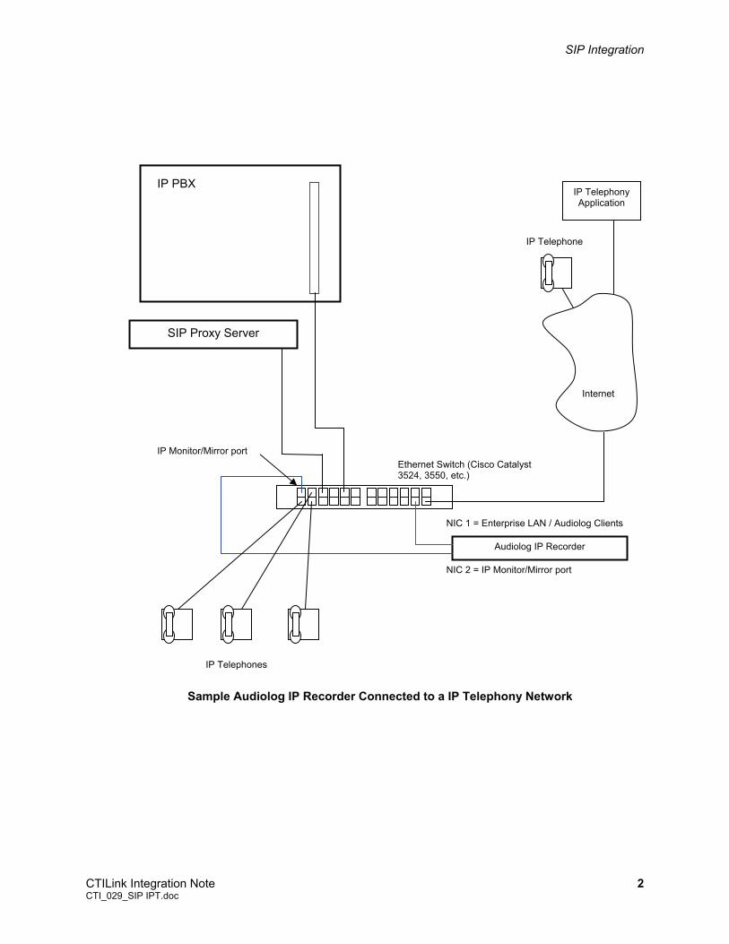
Unlike conventional telephony where the Audiolog taps across a pair of wires or emulates a telephone set, with IP telephony, the Audiolog must monitor the packet traffic within the IP telephony network. The Audiolog recorder must determine which packets are encoded voice packets and which packets are associated with a device Audiolog is programmed to record. To accomplish this, the Audiolog is equipped with additional 10/100 Ethernet Network Interface cards which are connected to the IP network.
One connection is the standard LAN connection used connect Audiolog to client PCs. Additional connection(s) monitor the packet traffic and provide the “audio” connection. SIP is fundamentally different from other IP Telephony integrations in that it does not interface to a CTI server. The recording control is determined by the SIP call control protocol. Although there is no CTI server to connect to, CTILink is still used in this application to process call control from SIP.
An Audiolog recorder configured for IP Telephony records the audio of a conversation in two streams and writes both streams to an .avi file rather than a .wav file. The recording can be played back with Audiolog’s Multi-Channel Player or any multi-media player capable of playing .avi files.
In IP Telephony integration, the channels on the Audiolog are pooled. There is no one-to-one correspondence between a device (telephone) and a channel. Recordings take place on the channels that have been idle the longest.
Audiolog detects the compression rate at the beginning of a call and automatically sets the recording compression rate per call.
SIP Integration
CTILink Integration Note 2 CTI_029_SIP IPT.doc
Audiolog IP Recorder
Internet
IP Telephony Application
IP Telephones
IP Telephone
Ethernet Switch (Cisco Catalyst 3524, 3550, etc.)
NIC 1 = Enterprise LAN / Audiolog Clients
NIC 2 = IP Monitor/Mirror port
IP Monitor/Mirror port
Sample Audiolog IP Recorder Connected to a IP Telephony Network
IP PBX
SIP Proxy Server
SIP Integration
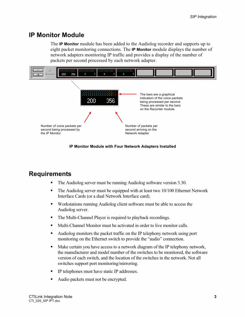
IP Monitor Module The IP Monitor module has been added to the Audiolog recorder and supports up to eight packet monitoring connections. The IP Monitor module displays the number of network adapters monitoring IP traffic and provides a display of the number of packets per second processed by each network adapter.
Number of packets per second arriving on the Network Adapter
Number of voice packets per second being processed by the IP Monitor.
The bars are a graphical indication of the voice packets being processed per second. These are similar to the bars on the Recorder module.
IP Monitor Module with Four Network Adapters Installed
Requirements The Audiolog server must be running Audiolog software version 3.30.
The Audiolog server must be equipped with at least two 10/100 Ethernet Network Interface Cards (or a dual Network Interface card).
Workstations running Audiolog client software must be able to access the Audiolog server.
The Multi-Channel Player is required to playback recordings.
Multi-Channel Monitor must be activated in order to live monitor calls.
Audiolog monitors the packet traffic on the IP telephony network using port monitoring on the Ethernet switch to provide the “audio” connection.
Make certain you have access to a network diagram of the IP telephony network, the manufacturer and model number of the switches to be monitored, the software version of each switch, and the location of the switches in the network. Not all switches support port monitoring/mirroring.
IP telephones must have static IP addresses.
Audio packets must not be encrypted.
CTILink Integration Note 3 CTI_029_SIP IPT.doc
SIP Integration
Determine the model number of the IP telephones to be recorded.
Determine the compression rate(s) being used (G.711, G.729a, G.723).
Other Considerations Contact your local Audiolog reseller or email [email protected] if any of the following situations exist on the IP telephony network:
Determine if there are multiple sites.
Determine if silence compression is in use.
LAN Connections The connections between the Audiolog recorder and the IP telephony network depend on the network topology and the switches to be monitored. One connection is always used as the connection to the enterprise LAN for Audiolog clients.
Up to eight monitor/mirror ports can be connected to the Audiolog recorder. A connection is made to the port designated as a monitor/mirror port on the Switch.
Make a note of which network adapter is connected to a Monitor port. The adapter names must be entered in Audiolog’s registry.
CTILink Integration Note 4 CTI_029_SIP IPT.doc
SIP Integration
Audiolog Setup
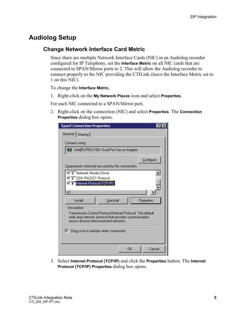
Change Network Interface Card Metric Since there are multiple Network Interface Cards (NIC) in an Audiolog recorder configured for IP Telephony, set the Interface Metric on all NIC cards that are connected to SPAN/Mirror ports to 2. This will allow the Audiolog recorder to connect properly to the NIC providing the CTILink (leave the Interface Metric set to 1 on this NIC).
To change the Interface Metric,
1. Right-click on the My Network Places icon and select Properties.
For each NIC connected to a SPAN/Mirror port,
2. Right-click on the connection (NIC) and select Properties. The Connection Properties dialog box opens.
3. Select Internet Protocol (TCP/IP) and click the Properties button. The Internet
Protocol (TCP/IP) Properties dialog box opens.
CTILink Integration Note 5 CTI_029_SIP IPT.doc
SIP Integration
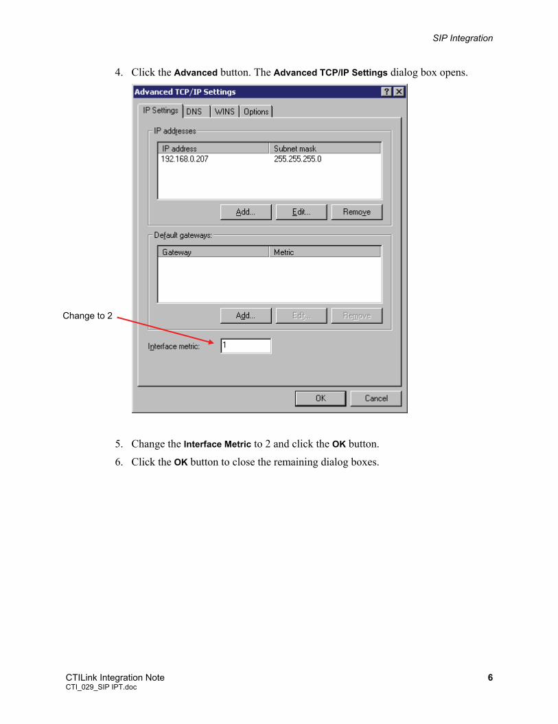
4. Click the Advanced button. The Advanced TCP/IP Settings dialog box opens.
Change to 2
5. Change the Interface Metric to 2 and click the OK button.
6. Click the OK button to close the remaining dialog boxes.
CTILink Integration Note 6 CTI_029_SIP IPT.doc
SIP Integration
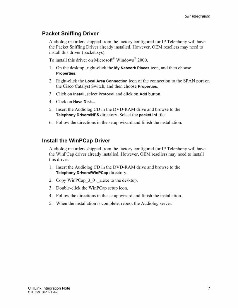
Packet Sniffing Driver Audiolog recorders shipped from the factory configured for IP Telephony will have the Packet Sniffing Driver already installed. However, OEM resellers may need to install this driver (packet.sys).
To install this driver on Microsoft® Windows® 2000,
1. On the desktop, right-click the My Network Places icon, and then choose Properties.
2. Right-click the Local Area Connection icon of the connection to the SPAN port on the Cisco Catalyst Switch, and then choose Properties.
3. Click on Install, select Protocol and click on Add button.
4. Click on Have Disk...
5. Insert the Audiolog CD in the DVD-RAM drive and browse to the Telephony Drivers\NPS directory. Select the packet.inf file.
6. Follow the directions in the setup wizard and finish the installation.
Install the WinPCap Driver Audiolog recorders shipped from the factory configured for IP Telephony will have the WinPCap driver already installed. However, OEM resellers may need to install this driver.
1. Insert the Audiolog CD in the DVD-RAM drive and browse to the Telephony Drivers\WinPCap directory.
2. Copy WinPCap_3_01_a.exe to the desktop.
3. Double-click the WinPCap setup icon.
4. Follow the directions in the setup wizard and finish the installation.
5. When the installation is complete, reboot the Audiolog server.
CTILink Integration Note 7 CTI_029_SIP IPT.doc
SIP Integration
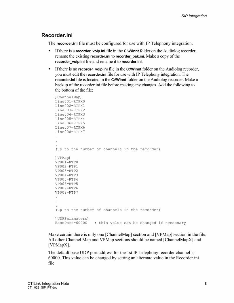
Recorder.ini The recorder.ini file must be configured for use with IP Telephony integration.
If there is a recorder_voip.ini file in the C:\Winnt folder on the Audiolog recorder, rename the existing recorder.ini to recorder_bak.ini. Make a copy of the recorder_voip.ini file and rename it to recorder.ini.
If there is no recorder_voip.ini file in the C:\Winnt folder on the Audiolog recorder, you must edit the recorder.ini file for use with IP Telephony integration. The recorder.ini file is located in the C:\Winnt folder on the Audiolog recorder. Make a backup of the recorder.ini file before making any changes. Add the following to the bottom of the file: [ChannelMap] Line001=RTPX0 Line002=RTPX1 Line003=RTPX2 Line004=RTPX3 Line005=RTPX4 Line006=RTPX5 Line007=RTPX6 Line008=RTPX7 . . . (up to the number of channels in the recorder) [VPMap] VP001=RTP0 VP002=RTP1 VP003=RTP2 VP004=RTP3 VP005=RTP4 VP006=RTP5 VP007=RTP6 VP008=RTP7 . . . (up to the number of channels in the recorder) [UDPParameters] BasePort=60000 ; this value can be changed if necessary
Make certain there is only one [ChannelMap] section and [VPMap] section in the file. All other Channel Map and VPMap sections should be named [ChannelMapX] and [VPMapX].
The default base UDP port address for the 1st IP Telephony recorder channel is 60000. This value can be changed by setting an alternate value in the Recorder.ini file.
CTILink Integration Note 8 CTI_029_SIP IPT.doc
SIP Integration
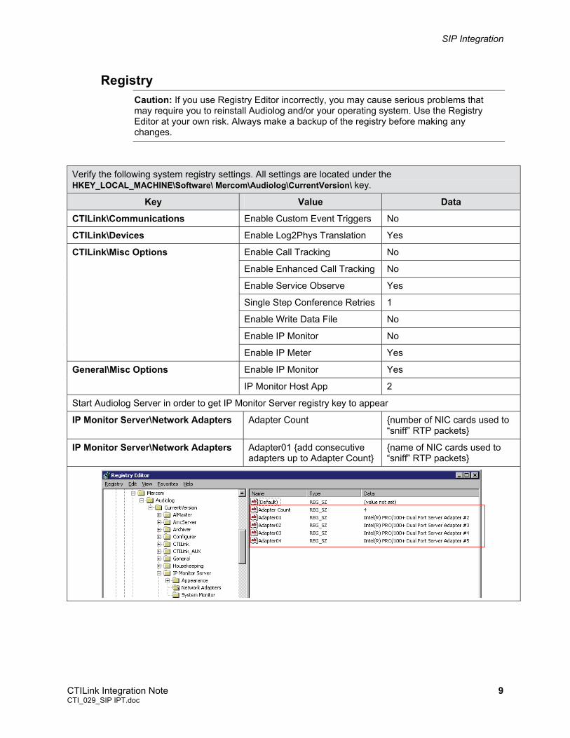
Registry Caution: If you use Registry Editor incorrectly, you may cause serious problems that may require you to reinstall Audiolog and/or your operating system. Use the Registry Editor at your own risk. Always make a backup of the registry before making any changes.
Verify the following system registry settings. All settings are located under the HKEY_LOCAL_MACHINE\Software\ Mercom\Audiolog\CurrentVersion\ key.
Key Value Data
CTILink\Communications Enable Custom Event Triggers No
CTILink\Devices Enable Log2Phys Translation Yes
Enable Call Tracking No
Enable Enhanced Call Tracking No
Enable Service Observe Yes
Single Step Conference Retries 1
Enable Write Data File No
Enable IP Monitor No
CTILink\Misc Options
Enable IP Meter Yes
Enable IP Monitor Yes General\Misc Options
IP Monitor Host App 2
Start Audiolog Server in order to get IP Monitor Server registry key to appear
IP Monitor Server\Network Adapters Adapter Count {number of NIC cards used to “sniff” RTP packets}
IP Monitor Server\Network Adapters Adapter01 {add consecutive adapters up to Adapter Count}
{name of NIC cards used to “sniff” RTP packets}
CTILink Integration Note 9 CTI_029_SIP IPT.doc
SIP Integration
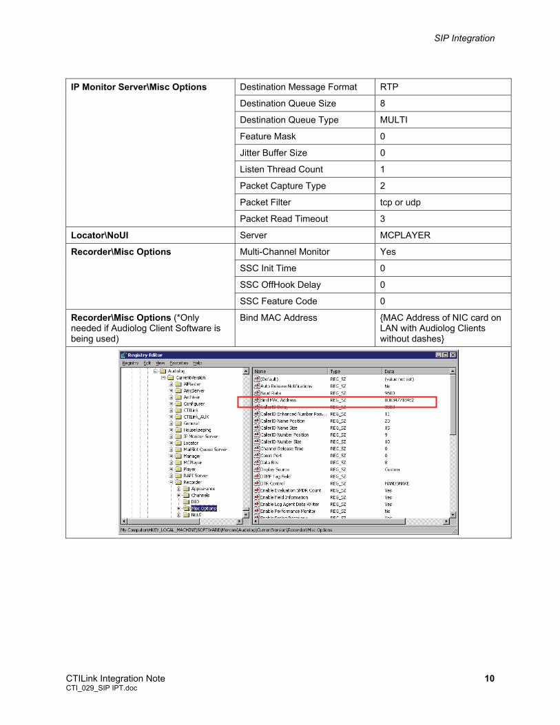
Destination Message Format RTP
Destination Queue Size 8
Destination Queue Type MULTI
Feature Mask 0
Jitter Buffer Size 0
Listen Thread Count 1
Packet Capture Type 2
Packet Filter tcp or udp
IP Monitor Server\Misc Options
Packet Read Timeout 3
Locator\NoUI Server MCPLAYER
Multi-Channel Monitor Yes
SSC Init Time 0
SSC OffHook Delay 0
Recorder\Misc Options
SSC Feature Code 0
Recorder\Misc Options (*Only needed if Audiolog Client Software is being used)
Bind MAC Address {MAC Address of NIC card on LAN with Audiolog Clients without dashes}
CTILink Integration Note 10 CTI_029_SIP IPT.doc
SIP Integration
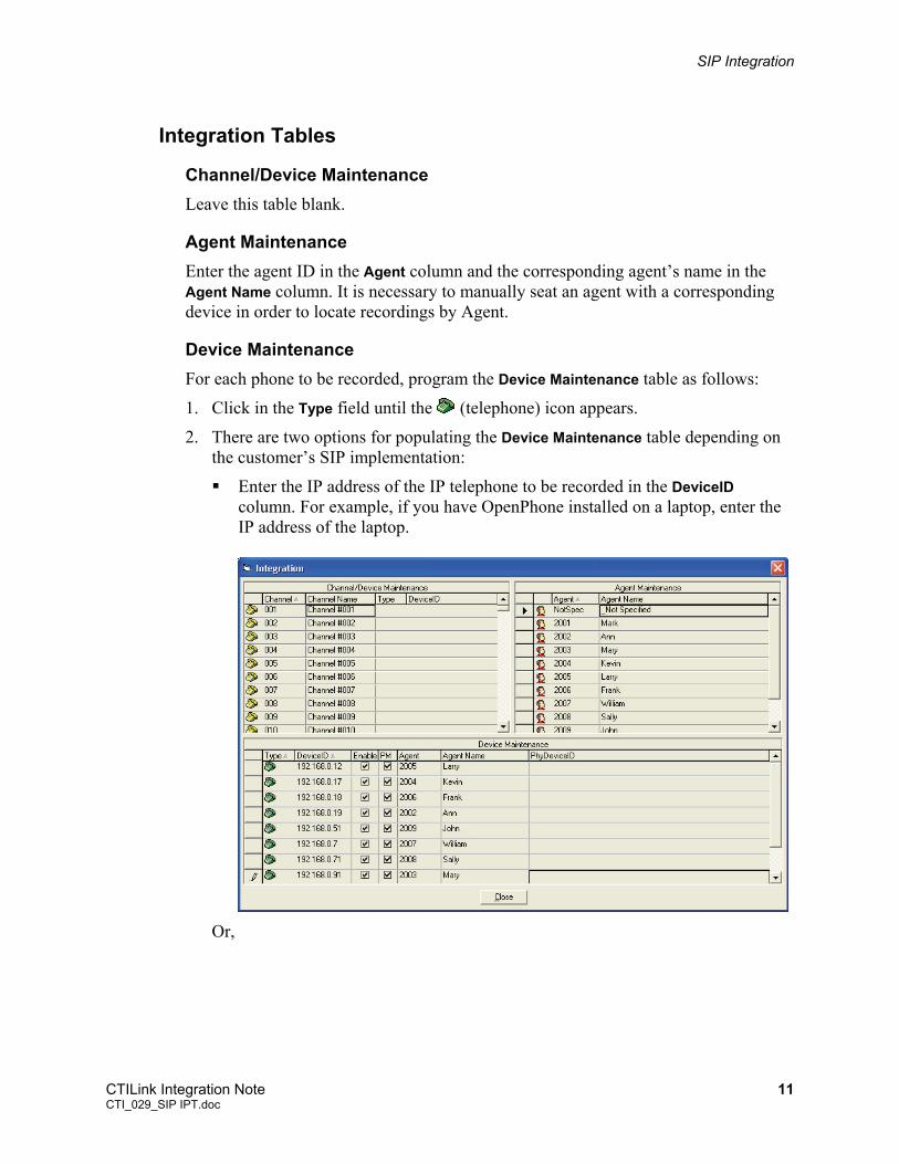
Integration Tables
Channel/Device Maintenance Leave this table blank.
Agent Maintenance Enter the agent ID in the Agent column and the corresponding agent’s name in the Agent Name column. It is necessary to manually seat an agent with a corresponding device in order to locate recordings by Agent.
Device Maintenance For each phone to be recorded, program the Device Maintenance table as follows:
1. Click in the Type field until the (telephone) icon appears.
2. There are two options for populating the Device Maintenance table depending on the customer’s SIP implementation:
Enter the IP address of the IP telephone to be recorded in the DeviceID column. For example, if you have OpenPhone installed on a laptop, enter the IP address of the laptop.
Or,
CTILink Integration Note 11 CTI_029_SIP IPT.doc
SIP Integration
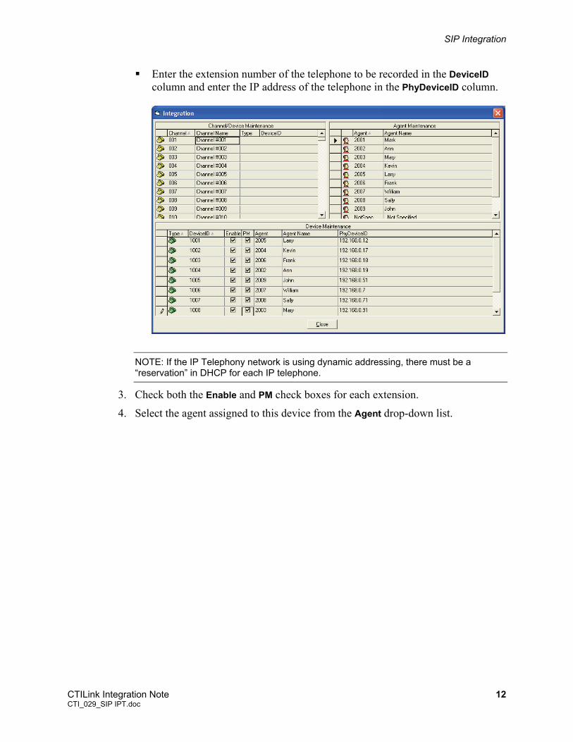
Enter the extension number of the telephone to be recorded in the DeviceID column and enter the IP address of the telephone in the PhyDeviceID column.
NOTE: If the IP Telephony network is using dynamic addressing, there must be a “reservation” in DHCP for each IP telephone.
3. Check both the Enable and PM check boxes for each extension.
4. Select the agent assigned to this device from the Agent drop-down list.
CTILink Integration Note 12 CTI_029_SIP IPT.doc
SIP Integration
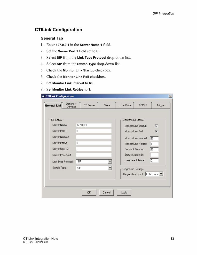
CTILink Configuration
General Tab 1. Enter 127.0.0.1 in the Server Name 1 field.
2. Set the Server Port 1 field set to 0.
3. Select SIP from the Link Type Protocol drop-down list.
4. Select SIP from the Switch Type drop-down list.
5. Check the Monitor Link Startup checkbox.
6. Check the Monitor Link Poll checkbox.
7. Set Monitor Link Interval to 60.
8. Set Monitor Link Retries to 1.
CTILink Integration Note 13 CTI_029_SIP IPT.doc
SIP Integration
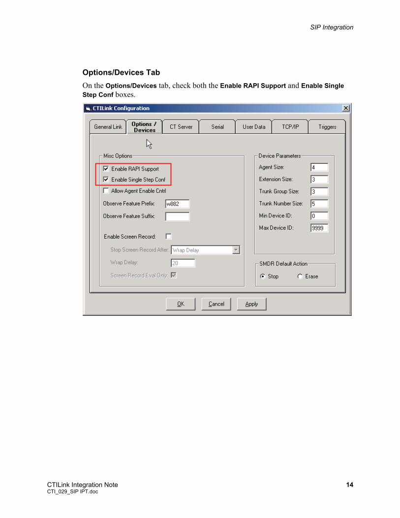
Options/Devices Tab On the Options/Devices tab, check both the Enable RAPI Support and Enable Single Step Conf boxes.
CTILink Integration Note 14 CTI_029_SIP IPT.doc
SIP Integration
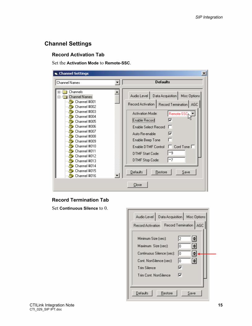
Channel Settings
Record Activation Tab Set the Activation Mode to Remote-SSC.
Record Termination Tab Set Continuous Silence to 0.
CTILink Integration Note 15 CTI_029_SIP IPT.doc
SIP Integration
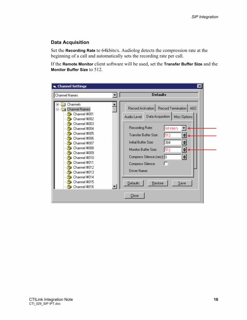
Data Acquisition Set the Recording Rate to 64kbits/s. Audiolog detects the compression rate at the beginning of a call and automatically sets the recording rate per call.
If the Remote Monitor client software will be used, set the Transfer Buffer Size and the Monitor Buffer Size to 512.
CTILink Integration Note 16 CTI_029_SIP IPT.doc
SIP Integration
Client Software
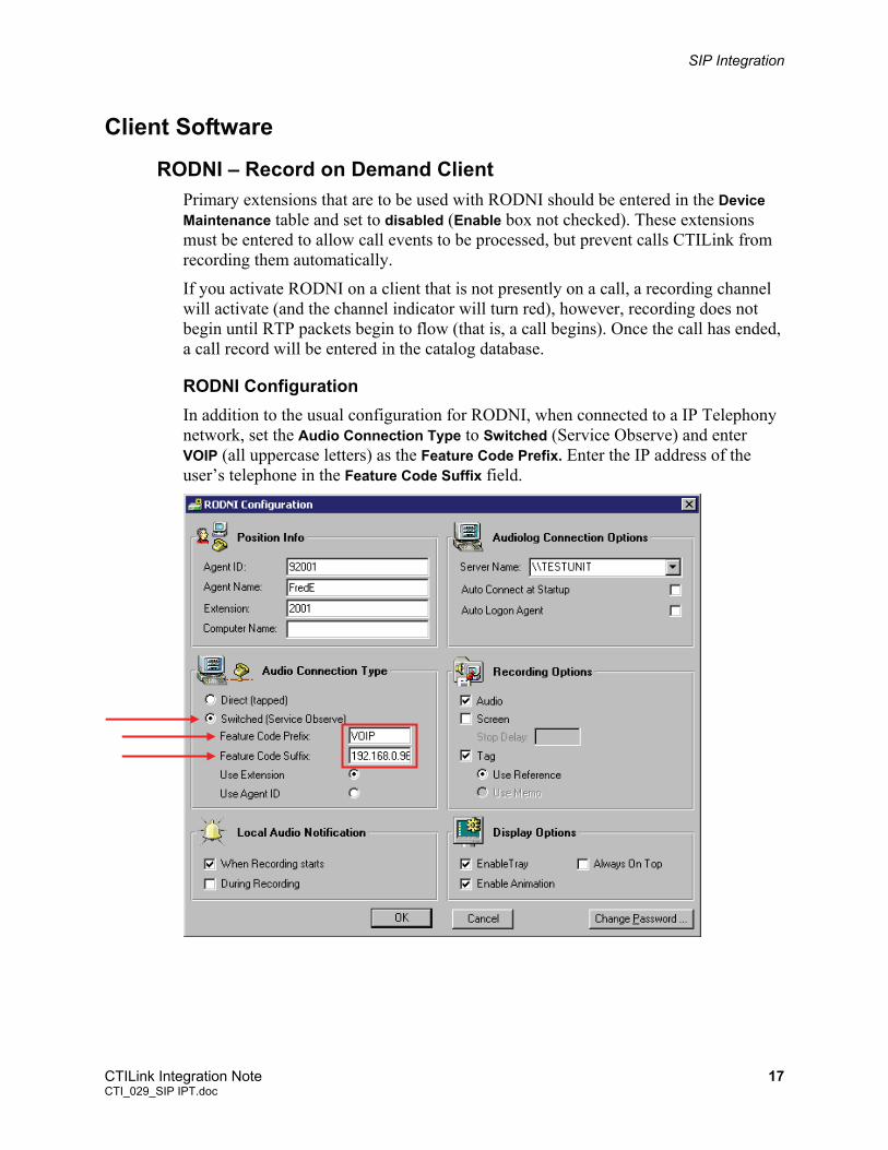
RODNI – Record on Demand Client Primary extensions that are to be used with RODNI should be entered in the Device Maintenance table and set to disabled (Enable box not checked). These extensions must be entered to allow call events to be processed, but prevent calls CTILink from recording them automatically.
If you activate RODNI on a client that is not presently on a call, a recording channel will activate (and the channel indicator will turn red), however, recording does not begin until RTP packets begin to flow (that is, a call begins). Once the call has ended, a call record will be entered in the catalog database.
RODNI Configuration In addition to the usual configuration for RODNI, when connected to a IP Telephony network, set the Audio Connection Type to Switched (Service Observe) and enter VOIP (all uppercase letters) as the Feature Code Prefix. Enter the IP address of the user’s telephone in the Feature Code Suffix field.
CTILink Integration Note 17 CTI_029_SIP IPT.doc
SIP Integration
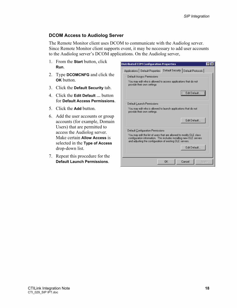
DCOM Access to Audiolog Server The Remote Monitor client uses DCOM to communicate with the Audiolog server. Since Remote Monitor client supports event, it may be necessary to add user accounts to the Audiolog server’s DCOM applications. On the Audiolog server,
1. From the Start button, click Run.
2. Type DCOMCNFG and click the OK button.
3. Click the Default Security tab.
4. Click the Edit Default … button for Default Access Permissions.
5. Click the Add button.
6. Add the user accounts or group accounts (for example, Domain Users) that are permitted to access the Audiolog server. Make certain Allow Access is selected in the Type of Access drop-down list.
7. Repeat this procedure for the Default Launch Permissions.
CTILink Integration Note 18 CTI_029_SIP IPT.doc
SIP Integration
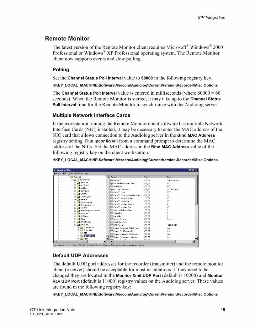
Remote Monitor The latest version of the Remote Monitor client requires Microsoft® Windows® 2000 Professional or Windows® XP Professional operating system. The Remote Monitor client now supports events and slow polling.
Polling Set the Channel Status Poll Interval value to 60000 in the following registry key. HKEY_LOCAL_MACHINE\Software\Mercom\Audiolog\CurrentVersion\Recorder\Misc Options
The Channel Status Poll Interval value is entered in milliseconds (where 60000 = 60 seconds). When the Remote Monitor is started, it may take up to the Channel Status Poll Interval time for the Remote Monitor to synchronize with the Audiolog server.
Multiple Network Interface Cards If the workstation running the Remote Monitor client software has multiple Network Interface Cards (NIC) installed, it may be necessary to enter the MAC address of the NIC card that allows connection to the Audiolog server in the Bind MAC Address registry setting. Run ipconfig /all from a command prompt to determine the MAC address of the NICs. Set the MAC address in the Bind MAC Address value of the following registry key on the client workstation: HKEY_LOCAL_MACHINE\Software\Mercom\Audiolog\CurrentVersion\Recorder\Misc Options
Default UDP Addresses The default UDP port addresses for the recorder (transmitter) and the remote monitor client (receiver) should be acceptable for most installations. If they need to be changed they are located in the Monitor Xmit UDP Port (default is 10200) and Monitor Rcv UDP Port (default is 11000) registry values on the Audiolog server. These values are found in the following registry key: HKEY_LOCAL_MACHINE\Software\Mercom\Audiolog\CurrentVersion\Recorder\Misc Options
CTILink Integration Note 19 CTI_029_SIP IPT.doc
SIP Integration
IRIS – Manual Recording IRIS currently does not support manual recording (record on demand) for IP Telephony.
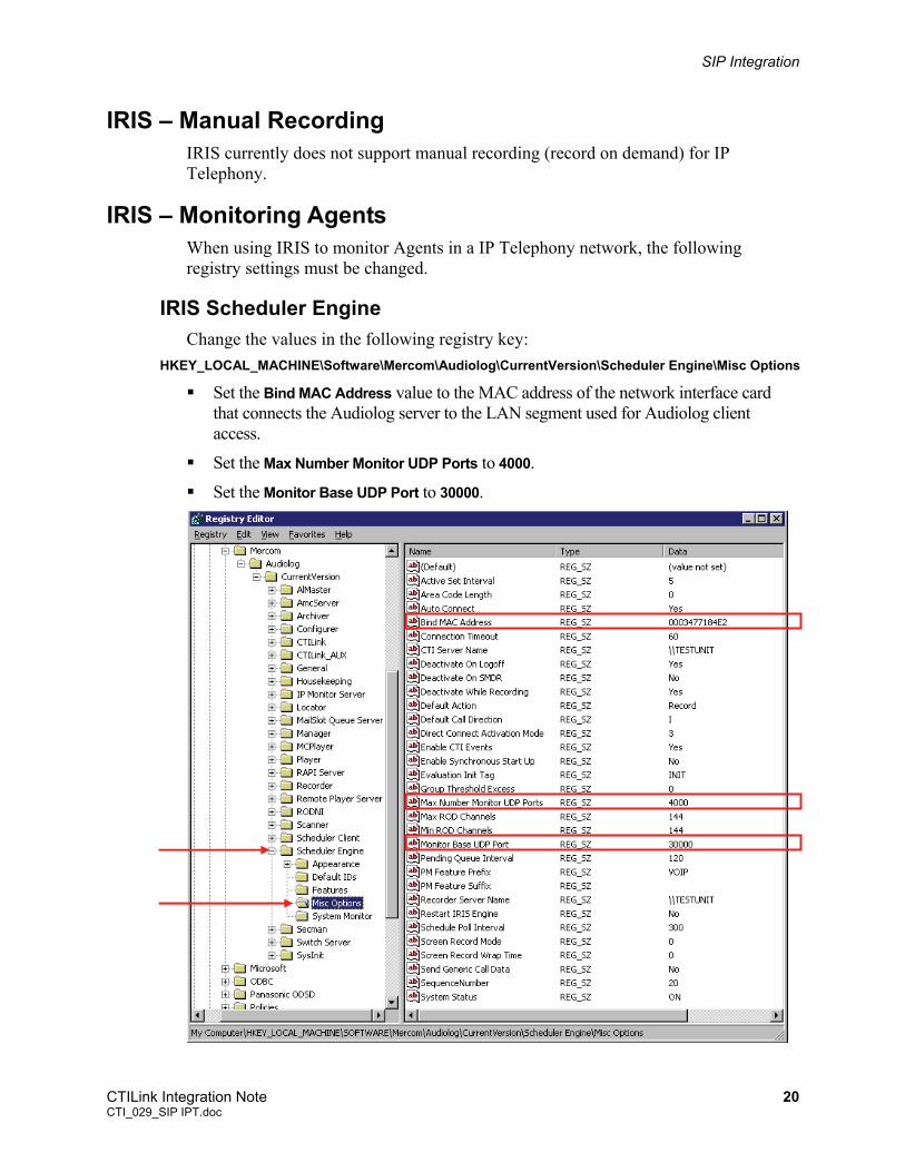
IRIS – Monitoring Agents When using IRIS to monitor Agents in a IP Telephony network, the following registry settings must be changed.
IRIS Scheduler Engine Change the values in the following registry key:
HKEY_LOCAL_MACHINE\Software\Mercom\Audiolog\CurrentVersion\Scheduler Engine\Misc Options
Set the Bind MAC Address value to the MAC address of the network interface card that connects the Audiolog server to the LAN segment used for Audiolog client access.
Set the Max Number Monitor UDP Ports to 4000.
Set the Monitor Base UDP Port to 30000.
CTILink Integration Note 20 CTI_029_SIP IPT.doc
SIP Integration
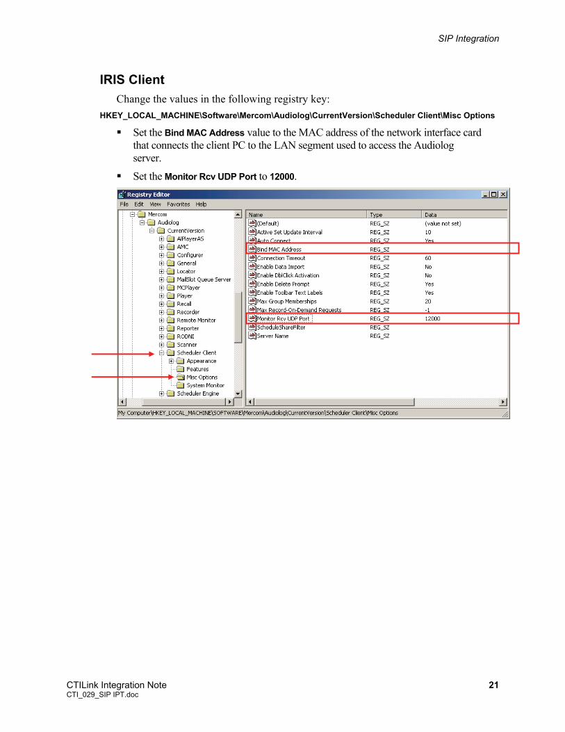
IRIS Client Change the values in the following registry key:
HKEY_LOCAL_MACHINE\Software\Mercom\Audiolog\CurrentVersion\Scheduler Client\Misc Options
Set the Bind MAC Address value to the MAC address of the network interface card that connects the client PC to the LAN segment used to access the Audiolog server.
Set the Monitor Rcv UDP Port to 12000.
CTILink Integration Note 21 CTI_029_SIP IPT.doc
SIP Integration
Test the Integration Since Audiolog is based on both hardware and software components, there are several steps involved to verify that both have been installed correctly:
Ensure that channels can be monitored and recordings can be created
Ensure that recordings can be accessed and played back from the Catalog
Ensure that there is network communication between the server and client
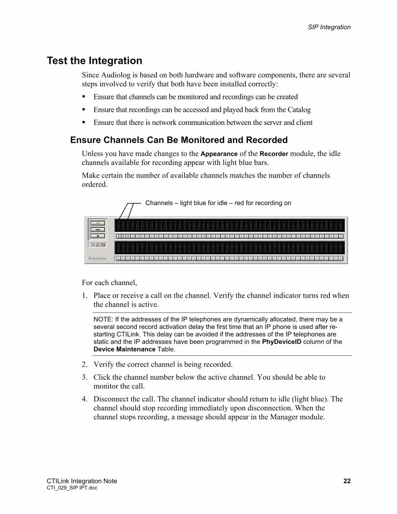
Ensure Channels Can Be Monitored and Recorded Unless you have made changes to the Appearance of the Recorder module, the idle channels available for recording appear with light blue bars.
Make certain the number of available channels matches the number of channels ordered.
Channels – light blue for idle – red for recording on
For each channel,
1. Place or receive a call on the channel. Verify the channel indicator turns red when the channel is active.
NOTE: If the addresses of the IP telephones are dynamically allocated, there may be a several second record activation delay the first time that an IP phone is used after re-starting CTILink. This delay can be avoided if the addresses of the IP telephones are static and the IP addresses have been programmed in the PhyDeviceID column of the Device Maintenance Table.
2. Verify the correct channel is being recorded.
3. Click the channel number below the active channel. You should be able to monitor the call.
4. Disconnect the call. The channel indicator should return to idle (light blue). The channel should stop recording immediately upon disconnection. When the channel stops recording, a message should appear in the Manager module.
CTILink Integration Note 22 CTI_029_SIP IPT.doc
SIP Integration
Ensure that Recordings Can Be Accessed from the Catalog After you have created several recordings, you should verify that they can be found in the catalog and then played back.
Be sure that you are logged-on with your User Name and Password. If you receive a Please Logon screen when trying to start the Call Locator, enter your User Name and Password, and click OK. Then start the Call Locator again.
To play back the recordings just created,
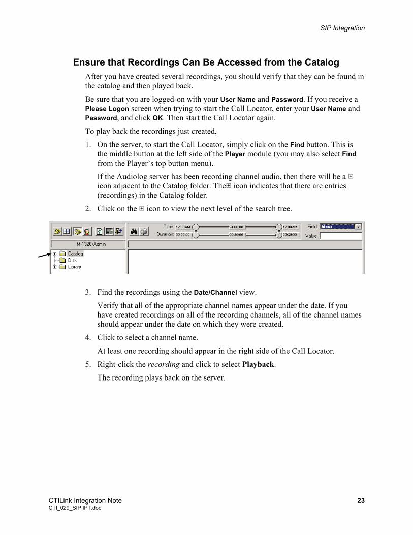
1. On the server, to start the Call Locator, simply click on the Find button. This is the middle button at the left side of the Player module (you may also select Find from the Player’s top button menu).
If the Audiolog server has been recording channel audio, then there will be a icon adjacent to the Catalog folder. The icon indicates that there are entries (recordings) in the Catalog folder.
Click on the 2. icon to view the next level of the search tree.
pear under the date. If you es
4. pear in the right side of the Call Locator.
5.
3. Find the recordings using the Date/Channel view.
Verify that all of the appropriate channel names aphave created recordings on all of the recording channels, all of the channel namshould appear under the date on which they were created.
Click to select a channel name.
At least one recording should ap
Right-click the recording and click to select Playback.
The recording plays back on the server.
CTILink Integration Note 23 CTI_029_SIP IPT.doc
SIP Integration
Appendix A – Configure a SPAN Port on a Cisco Catalyst 3524 Switch
Switch Port Analyzer (SPAN) These instructions presume you have already established a telnet session to the Catalyst Switch.
IMPORTANT: Consult with the customer’s networking organization before attempting any changes. These instructions are only meant to show the types of commands used on an IP Switch to copy RTP packets from the customer’s network to the Audiolog. It is necessary to carefully plan with the customer’s network and voice organizations how to achieve an efficient architecture for copying only RTP packet from the desired IP phones and gateways.
The port selected must belong to the same VLAN as the ports to be monitored.
If you don't specify any interface in the port monitor command, all other ports belonging to the same VLAN as the interface will be monitored.
Configure a SPAN port Using the Command Line Interface 1. At the “>” prompt, type enable to enter the privileged EXEC mode. The prompt
should change to “#” preceded by the name of the switch.
2. At the “#” prompt, type configure terminal.
3. At the (config)# prompt, type interface and the port being used as the SPAN port. For example, if FastEthernet 0/1 is to be the SPAN port, type interface fa0/1.
4. For each port to be monitored, at the (config-if)# prompt, type port monitor and the port to be monitored. For example, if you wish to monitor port FastEthernet 0/3, type port monitor fa0/3.
5. When all ports to be monitored have been entered, type end to return to privileged EXEC mode.
6. Type show port monitor to verify your entries.
7. Type disable to return to user EXEC mode.
CTILink Integration Note 24 CTI_029_SIP IPT.doc
SIP Integration
Appendix B – Configure a SPAN Session on a Cisco Catalyst 3550 Switch
These instructions presume you have already established a telnet session to the Catalyst Switch.
IMPORTANT: Consult with the customer’s networking organization before attempting any changes. These instructions are only meant to show the types of commands used on an IP Switch to copy RTP packets from the customer’s network to the Audiolog. It is necessary to carefully plan with the customer’s network and voice organizations how to achieve an efficient architecture for copying only RTP packet from the desired IP phones and gateways.
Create a Span Session Follow the instructions below to configure a SPAN session using the CLI, or refer to the Catalyst 3550 Multilayer Switch Software Configuration Guide for detailed instructions on configuring a SPAN port.
1. At the “>” prompt, type enable to enter the privileged EXEC mode. The prompt should change to “#” preceded by the name of the switch.
2. At the “#” prompt, type configure terminal to enter global configuration mode.
3. Clear any existing SPAN configuration by typing no monitor session and the session number 1 or 2. For example, no monitor session 1. Optionally you can add all (to remove all span sessions), local (to remove local span sessions), or remote (to remove remote span sessions).
4. Specify the source interface to be monitored by typing monitor session 1 source interface and the port to monitor, for example, fastEthernet0/1. Use a comma to separate a series of ports, or a hyphen in to specify a range of ports. Enter a space after a comma or a space before and after a hyphen.
5. Specify the destination (monitoring) interface by typing monitor session 1 destination interface and the port to monitor, for example, fastEthernet0/10.
6. When all ports to be monitored have been entered, type end to return to privileged EXEC mode.
7. Type show monitor to verify your entries.
8. If desired, type copy running-config startup-config to save your entries in the configuration file.
CTILink Integration Note 25 CTI_029_SIP IPT.doc
SIP Integration
Remove a Port from a Span Session Follow the instructions below to remove a port from a SPAN session.
1. At the “>” prompt, type enable to enter the privileged EXEC mode. The prompt should change to “#” preceded by the name of the switch.
2. At the “#” prompt, type configure terminal to enter global configuration mode.
3. Type no monitor session and the session number 1 or 2 followed by the source interface and source interface (monitored port) to be removed. For example, no monitor session 1 source interface fastEthernet0/3.
4. Type end to return to privileged EXEC mode.
5. Type show monitor to verify your entries.
6. If desired, type copy running-config startup-config to save your entries in the configuration file.
Specify a VLAN to Monitor 1. At the “>” prompt, type enable to enter the privileged EXEC mode. The prompt
should change to “#” preceded by the name of the switch.
2. At the “#” prompt, type configure terminal to enter global configuration mode.
3. Clear any existing SPAN configuration by typing no monitor session and the session number 1 or 2. For example, no monitor session 1. Optionally you can add all (to remove all span sessions), local (to remove local span sessions), or remote (to remove remote span sessions).
4. Specify the VLAN to be monitored by typing monitor session 1 source vlan and the vlan-id to monitor, for example, vlan 10. Use a comma to separate a series of vlans, or a hyphen in to specify a range of vlans. Enter a space after a comma or a space before and after a hyphen (for example, vlan 1 – 3).
5. Specify the destination (monitoring) interface by typing monitor session 1 destination interface and the port to monitor, for example, fastEthernet0/10.
6. Type end to return to privileged EXEC mode.
7. Type show monitor to verify your entries.
8. If desired, type copy running-config startup-config to save your entries in the configuration file.
NOTE: If you wish to create an RSPAN session, refer to the Catalyst 3550 Multilayer Switch Software Configuration Guide for instructions.
CTILink Integration Note 26 CTI_029_SIP IPT.doc