Embed Size (px)
Citation preview

AUGUST 1982 $1.95

PLEASE PRINT Yes, send me your new Full Line Microphone /Circuitry Catalog, AL700. (Outside the U.S., enclose $2.00 for postage and handling.) Name
Address
City State Zip
J
Special microphones
for special sound requirements
As an audio specialist, you know making do with "utility' microphones isn't good enough. You need a complete assortment of microphones, each suited for specific applications. Microphones that not only sound superb but are built to withstand the abuse of session to session punishment.
Shure SM line professional microphones offer built -in ruggedness and reliability and are designed to give you the optimum performance you need in every circumstance, whether it be for a bass drum (SM7): an acoustic stringed instrument (SM17): percussion instruments (SM56 and SM57): snare drum or acoustic guitar (SM81): amplified instruments (SM53 and SM54): studio quality vocals inside the studio (SM59): studio quality vocals outside the studio (SM85): stand -up interviews (SM61 and SM63): desk -top applications (SM33) ... or whatever your needs.
12) SHURE The Sound of the Professionals®
Shure Brothers Inc., Dept. 63. 222 Hartrey Ave., Evanston. IL 60204 In Canada: A.C. Simmonds & Sons Limited
Manufacturer of high fidelity components. microphones. loudspeakers. sound systems and related circuitry.
Circle l0 on Reader Service Card
...under one cover For all the facts on Shure's full line of professional micro- phones, fill out and return the coupon below for your FREE copy of our new 72 page catalog describing over 150 microphones. No matter what your sonic require- ments. there's a Shure microphone that fills the bill.

Publisher Larry Zide
Editor John M. Woram
European Editor John Borwick
Associate Editor Mark B. Waldstein Production & Layout
David Kramer Advertising Coordinator
Karen Cohn Classified Advertising
Carol Vitelli Book Sales
Lydia Calogrides Circulation Manager
Eloise Beach
Art Director Bob Laurie
Graphics K & S Graphics
Typography Spartan Phototype Co.
sales offices Roy McDonald Associates, Inc.
Dallas, Texas 75207 First Continental Bank Bldg.
5801 Marvin D. Love Freeway Suite 303
(214) 941-4461 Denver, Colorado Area
Englewood, Colorado 80112 14 Inverness Dr. East
Bldg. 1- Penthouse (303) 771-8181
Houston, Texas 77036 6901 Corporate Drive
Suite 210 (713) 988-5005
Los Angeles Area Glendale, California 91204 424 West Colorado Street
Suite 201 (213) 244 -8176 Portland Area
Hillsboro, Oregon 97123 510 South First
P.O. Box 696 (503) 640 -2011
San Francisco Area Emeryville, California 94608 265 Baybridge Office Plaza
5801 Christie Avenue (415) 653 -2122
Sagamore Publishing Co. New York
Plainview, NY 11803 1120 Old Country Rd.
(516) 433-6530
Eat your heart out Tron! This month's high -tech cover features UREI's co -axial driver with a diffraction buffer at the mouth of the horn. This driver is used in all UREI monitors. Thanks to Bartleby for the photo and Garden Wall Graphics for the video imaging.
DEPARTMENTS
LETTERS 6
AUGUST 1982 VOLUME 16, NO. 8
CALENDAR 8
EDITORIAL 25
CLASSIFIED 53
DIGITAL AUDIO Barry Blesser I0
THEORY AND PRACTICE Ken Pohlmann 16
SOUND REINFORCEMENT John Eargle 19
NEW PRODUCTS AND SERVICES 48
PEOPLE, PLACES HAPPENINGS 55
FEATURES
THE VENERABLE 604 Robert Harvey 26
COST -EFFICIENT SOUND INSULATION Michael Rettinger 35
CUSTOM EQUALIZATION: A SCIENCE AND AN ART 36
William C. Matthews
THE PARAMOUNT THEATRES NEW SOUND SYSTEM 40
Wolf Schneider
THE FET: BIG -TIME MATHEMATICS COMES TO AUDIO 44
Robert Berkovitz
DIRECTORY OF SPEAKER MANUFACTURERS 47
db. the Sound Enginecnng Magannc f ISSN 0011.7145) is published monthly by Sagamore Publishing Company. Inc. Finite con. tents rnIssright 1952 h Sagamore Publishing Cu., 1120 Old Country Road, Plainview, L.I., N.Y. 11%03. Ickphone(516)4336S30 db is published for those indo idua Is and firms in proles.wnal audio- recording. broadcast. audio- visual. sound reinforcement.con- sultants. video recording, him sound. etc. Application should be made un the subscription form in the rear of each issue. Subscrip- tions are $15.00 per year ($28.00 per year outside U.S. Possessions: $16.00 per sear Canada) in U.S. funds. Single copies are 51.95 each. Pditorial, Publishing and Sales Offices: 1120 Old Countq Road. Plains less, New York 11803. Controlled circulation postage paid at Plainview, NY 11803 and an additional mailing office.
You do better with sound system components and accessories from Communications
Company!
Room Audio Director
RAD -30 / Provides expandable (movable -wall) meeting room facilities with the ultimate con- trol for combining audio areas. You get touch -button audio status control in each area.
Fast Food Intercom
IC -28 This economical, reliable. versatile dual channel amplifier is perfect for fast food service systems, ticket window, teller cages. etc.
Projector Patch PP -2255 For quick, effective interfacing into sound systems from projectors or any audio in- put device in a sound system.
Record Patch RP -3030 For connection to speaker level line 25v -70v or voice coil impedence. Trans- former and resistor isolation against interference between source and up to four recorders.
Burst Octave Noise Generator
BONG -2 Provides pink noise and seven octave bands of noise with continuous variable control of level, burst period, and duty cycle.
SEND FOR OUR FULL -LINE CATALOG
AND LEARN MORE ABOUT THESE AND
OTHER SOUND SYSTEM COMPONENTS
AND TEST EQUIPMENT ... DESIGNED
BY A SOUND CONTRACTOR FOR SOUND
CONTRACTORS.
communcATons comPAnY
3490 Noell Street San Diego. CA 92110
17141297-3261
Circle 32 on Reader Service Card
BROTHERLY MICSMANSHIP To Till EDI IOR:
I liked your June editorial on "Mics- manship" very much. particularly Rule number three: "When miking vocalists. it is probably not a good idea to go direct." As an illustration. the following.
Many years ago. when I was in the CBS Field Department. I was assigned to cover the broadcast of a famous orches- tra. Network Operations laid down the rules for each broadcast location. specifying the mikes and their placement. The evening of the broadcast. the orchestra leader asked me to put up an extra mike for his brother. who was a
singer of sorts who loved to creep right into the mike. I protested but eventually agreed. I put up an extra mike (ribbon) but dead -ended it and, when the time came, picked up the exuberant vocalist on the announce mike, about five feet away. After the show the leader came to me and said his wife had called and told him that she had never heard his brother sing so well. He then proceeded to offer to buy me anything in the hotel. I think accepted only a glass of champagne, glad to get out of a tough spot so easily.
Incidentally, it is a tough job to replace the ribbon, as you probably know. One must not breathe in the direction of the ribbon and must learn to watch what you're doing out of the corner of an eye. Gain -riding a show today is. compara- tively. a piece of cake!
.IOEI. TAIT
IT COSTS TO GET THE BEST To THE EDITOR: It appears that somehow or other we have been dropped from your mailing list, as we haven't received a copy for quite some time now. We have always found db Magazine both interesting and useful, and I consider it, along with the Journal of the Audio Engineering Society, to be our best source of information about new products appear- ing on the market scene.
I would appreciate it if you would resume sending us your fine publication.
DEKE WARNER
db replies: Mr. Warner, we'd love to see you back on our mailing list too. But some rears ago, db became a paid -subscriber maga:ine. and we've been gradually phasing out those complimentary copies ever since. We're anxious to welcome you hack, but firs, we need your subscription order and cheek. Let us hear from you soon.
Index of Advertisers
Agfa -Gevaert 31 Altec 15
Ampex Cover Ill Audio + Design Recording 23 Bose I I
Cetec Gauss 22 Emilar 16
Fitzco I O
Garner 12
Goldlinè 18
JBL 7
Kimball 8
Klark -Teknik 19
Lexicon 32 Linear & Digital Systems, Inc 16
Maxell 24 Meyer Sound Labs 13
Modular Audio Device 14
Polyline 14
Shure Cover II Soundcraft 39 Standard Tape Labs 43 Teac 21
Telex 17
3M 37 TOA 9 UREI Cover IV White 8
Yamaha 29
Coming Next Month
In September, our topic will be Studio Systems. From Richard Koziol of WNCN comes: To Build the Impossible Dream: A Sound -Insulated Performance Studio Comes to the Big Apple." This article brings us a behind -the -scenes look at WNCN's major rebuilding project in the heart of Fun City. Last month, our own John Woram got to play Mike Wallace -and the result is his interview with Dr. Tom Stockham of Soundstream Recording Studios of Salt Lake City - coming in September. Also ahead for September is Part II of Robert Berkovitz's feature on the Fast Fourier Transform - which will include a computer program designed to show how the FFT works and a Digital Recording Services Direc- tory, courtesy of the RIAA. All this - and more -coming in September's db -The Sound Engineering Magazine.

Before you invest in new studio monitors, consider all the ankles.
No one Ira, its tell you hurt impor- tant flat frequenc response is in a studio monitors: But if you judge a
monitors performance by its on -axis response curve, you're only getting part of the story.
Most conventional monitors tend to narra v their dispersion as frequency increases. So while their on -axis response may he flat, their off -a \is response can roll off dramatically, liter- ally locking you into the on-axis "sweet spot:" Even worse, drastic changes in the horns directivity contribute signif- icantly to horn colorations.
Introducing the JRL Bi-Radial Studio Monitors.
At JB1, we've been investigating the relationship between on and off axis frequency response for several years. the result is a new generation of studio monitors that provide flat response over an exceptionally wide range of horizontal and vertical angles. The sweet spot and its traditional restrictions are essentially eliminated.
The key to this improved perfor- mance lies in the unique geometry of the monitors Bi- Radial horn! I)eel- oped with the aid of the latest com- puter design and analysis techniques, the horn provides constant cuyerage front its crossover point of 101)(1 Hz to beyond I(t kl lz.'I he 13i- Radial compound flare configuration main- tains precise control of the horns wide 1(1(1° x 1000 coverage angle.
I. Patent applied Ior.
JBL Professional Products Division
li pira/ bori_ onta/
Iirif,/ : c,iic,/
And the Bi- Radial horns perfor- mance advantages aren't limited to just beamwidth control. The horn's rapid flare rate, for instance. dramatically reduces second harmonic distortion and its shallow depth allows for opti- mal acoustic alignment of the drivers. This alignment lets the monitors fall well below the Blauert and Laws criteria for minimum audible time delay discrepancies.
But while the Bi- Radial horn offers outstanding performance, it's only part of the total package. The new monitors also incorporate JBI.s most advanced high and low fre- quency transducers and dividing networks. Working together, these
Polar response comparison ojo typical /meal t ̀ .: o-
::av eoaxia/ studio monitor and JKLs new t 1.T0 Bi- Radial studio monitor from from / k//z to lb k//_.
llil 130 b,17.-,
-1-130 cwrtietr/
components provide exceptionally smooth response, high power capa- city', extended bandwidth, and extremely low distortion.
Judge For Yourself Of course. the only tray to really
judge a studio monitor is to listen for yourself. So before you inn est in new monitors, ask your local JIB. profes- sional products dealer for a Bi- Radial monitor demonstration. And consider all the angles.
James B. Lansing Sound, Inc. 850(1 Balboa Boulevard P.O. Box 2201) Northridge, California ()I z2e1
Orel(' 23 on Reader Ser e Card

THE EXPANDABLE SYSTEM 200 ... .._.., _... o
0
Filter Display Broadband t Memory Control t Input Out Resolution Filters Tb0 and Options
Advanced Microprocessor Controlled Real Time Analyzer. Featuring:
Interchangeable Filters 45 dB Dynamic Range 16 ' 31 High Intensity LED Display 8 Non -volatile Memories
All Functions Microprocessor Controlled. Plug -in Options Available
3 Smoothing Time Constants Simultaneous Peak and Average Processing 0.5 dB Precision T,o Measurements
3 dB, 2 dB or 1 dB Resolution Built-in Pink Noise Generator 15 V Microphone Power Oscilloscope and Plotter Drive Optional Function Generator
- r iii.iinli! fi 1 ii111il1lilüilüìi,ütl
in strut re-merit s. inc_ P. O. Box 698. Austin. Texas 78767 512 892 -0752 TELEX 776409 WHITE INST AUS
More and more recording studios are discovering the great sound of the Kimball Professional Grand Here's why: The Kimball 6' 7" Professional Grand derives its heri-
tage of greatness from the worlds finest piano -the Bosendorfer. The scale and plate design are derived from the Bosendorfer Model 200, and the plate is ex- tra thick to assure maximum sustain and to avoid plate noise from hammer strikes. The Bosendorfer- derived scale and non - duplexed trebles enhance tonal depth, clarity, and pitch perception. The Kimball Professional Grand is specifically designed for clear, pure tonality, free of spurious noise and false harmonics. It also offers superior durability and tuning stability. Its entire struc- ture, including the soundboard, is of precision -laminated woods, greatly reducing differential expansion in changes of temperature and humidity.
. ' kmBall The key to sounding great`
1549 Royal St. Box 460 Jasper, IN 47516
Circle 15 on Reader Service c qtr i
For more information about the Kimball
Professional Grand, contact Wade Bray at (812) 482-1600.
IT'S WRONG THERE, IT'S WRONG HERE 7O 1 HP EDII OR:
In the article. "Resonators and Reverberation" in the November. 1981
db. an error appeared within the equation for calculating the slat spacing. r. as a function of cavity depth. D. The correct equation should read as follows:
r = w(4dD) /(2160' -fadD).
Bl.nzo G uzl \A Radio Beograd Beograd. Yugoslavia
db replies: So that's holy it's done in Yugoslavia!
Actually. tua / /y. we should have done it that way here too, and our thanks to reader Gu :ina for pointing out the error. (We left out the. terni in the denominator.) /f it's any consolation (it is to us), we did not make the same goof in the BASIC computer program that appeared later in the article.
Calendar SEPTEMBER
1 2-1 5 National Radio Broadcasters Association Convention. MGM Grand. Reno. Nevada. For more information contact: NR BA. 1705 DeSales St.. NW. Suite 500. Washington. D.C. 20036. Tel: (202) 466 -2030.
OCTOBER 19 -21, Syn -Aud -Con Sound Engineering 28 -30 Seminar. San Juan Capistrano.
CA. For more information contact: Syn -Aud -Con. P.O. Box 669, San Juan Capistrano, CA 92693. Tel: (800) 854 -6201.
6 -8 Natural Stereo Techniques for Re- cording Music Workshop. U niver- sity of Wisconsin -Eau Claire. For more information contact: Bert Spangler. Audio Coordinator, Media Development Center, UW- Eau Claire, Eau Claire, WI 54701. Tel: (715) 836 -2651.
22 -25 72nd AES Convention- Disney- land Hotel. Anaheim, CA. For more information contact: AES Headquarters, 60 E. 42nd St., New York, NY 10165. Tel: (212) 661- 8528, or Robert Trabue Davis, Altec Lansing, 1515 So. Manches- ter Ave., Anaheim, CA 92803. Tel: (714) 774 -2900.
NOVEMBER 7 -12 124th SMPTE Technical Confer-
ence and Equipment Exhibit. New York Hilton, New York, NY. For more information contact: SMPTE, 862 Scarsdale Ave., Scarsdale, NY 10583. Tel: (914) 472 -6606.

THE RUGGED, COMPACT TOA MONITORS DESIGNED TO PERFORM WHERE YOU NEED THEM THE MOST.
For the stage, the powerful SM -60 stage monitor speaker system. For the studio or stage, the equally powerful RS -21M reference mini -monitor. Both as small and as rugged as we could en- gineer them - without compromising the performance you need for accuracy and higher power -handling. They're everything you've always wanted in smaller, high quality monitors. And less. Less bulk and less set -up hassles.
Our SM -60 is a full- range, dual trans- ducer speaker system with a rated in- put of 70 watts? It features a sensitivity of 90 dB SPL -for operation at levels that really cut through. The frequency response is 110Hz to 16kHz- extended top and bottom to cover a broad musical range. And instead of cheap plastic or flimsy wooden boxes, we enclose the SM -60 in a tough, extruded aluminum shell with solid cast end panels.
When you make your set -ups with an SM -60 you've got options too. The ad- justable mounting bracket will securely attach the monitor to the top of the mic stand or anywhere along the stand itself. And when a speaker cable is stepped on, you're not going to lose the show because the connections are terminated with our exclusive positive -locking, Y4"
phone jack. The RS -21M is a closed enclosure,
full -range reference monitor that can handle a rated input of 35 watts" It gives you a sensitivity of 88 dB SPL (1W @lm) and a frequency response of 100Hz to 17kHz. The RS -21M is de- signed to fit right where you usually need it the most -right on top of the meter bridge of our RX Series boards.
Both new monitors can take the tough- est, continuous high power use on stage or in studio. They're companion
systems that join our compact RX Series consoles and the extension of our philosophy that professional sound gear doesn't have to be bulky, unsightly and a drag to set -up.
The SM -60, the RS -21M and our RX Series consoles -they're big on perfor- mance and stingy on space, the kind of studio equipment designed to perform where you need it the most. 16 ohms 8 ohms
Crafted in Japan ,
Proven in the States. TOA Electronics, Inc. 480 Carlton Court South San Francisco, Ca. 94080 (415) 588 -2538 Telex: 331 -332
In Canada: TOA Electronics, Inc. 10712 -181 Street Edmonton, Alberta T5S 1K8 (403) 489 -5511 Telex: 037 -43255

co ít SOUND. INC.
AAE " Concept One" Automation
AKG
AMPEX
AMPEX TAPE
AUDIOARTS ENGINEERING
BGW TANNOY
HANNAY
(Cable Reels)
EVENTIDE
IVIE
LEXICON
SENNHEISER
TECHNICS
VEGA
WIREWORKS
204 N. Midkiff Midland, Texas 79701
(915) 684 -0861
Circle /3 on Reader Service Card
BARRY BLESSER
Digital Audio
Digital Filters: Corruption
We all know that analog circuits will degrade performance from non- lineari- ties and additive noise. Taking special precautions tends to minimize it but it is
still a constant threat. On the other hand. the digital world has been represented as having no problems in this area (except for bit errors) because of the deter- ministic aspects of digital numbers. Alas, this is not really the case. In this discussion we will look at the two aspects of digital degradation: maximum signal limits and noise. Interestingly, these are the same issues as in the dynamic range limitations of the analog domain. The major difference between analog and digital dynamic range is that the analysis is much harder for digital, but the solutions are often much simpler.
MAXIMUM SIGNALS Much of our earlier discussions on the
maximum signal limits for A/D conver- sion apply to our consideration of filters. Since filters are made up of essentially two arithmetic operations- addition and multiplication -we should consider these for dynamic range issues. However. before we begin, we need to define the language for referring to our number system. If we call the LSB (least - significant bit) a I. then the maximum signal will be 2"-I for a monopolar peak (2" for peak -to- peak). This notation is not very convenient because the maximum signal is function of the number of bits. A more comfortable notation is to define the maximum signal as being +1 or - I and to treat the noise level as 2T' for an LSB. Thus we say that noise is reduced by adding more bits to the word.
With this notation, we observe that a
multiplier will never have a problem with large signals. The maximum output will occur for inputs of X = I and Y = I so that
Figure 1. An example of overflow error.
there will be no output overload when there is no input overload. On the other hand, the adder does produce a problem since two large signals of+ I will add up to +2. By our definition. +2 cannot be represented. One simple way to avoid this is to restrict the inputs X and Y to the adder to be less than 0.5. However, this is
not always possible or desirable. Another interesting problem comes
when we actually consider what happens when the adder tries to produce an output which is too large. To see this, let us consider a 6 -bit word represented in 2's complement. With this kind of notation. the MSB (most -significant bit) is the sign of the data. A negative number is the complement of a positive number with an added LSB. The number 011.111 which is
the maximum positive number in 6 bits is
31 32 or 0.96875. The negative number -31 32 is created by taking the comple- ment (100,000) and adding an LSB to give 100,001. Notice that we can subtract 000.001 from this number to get 100.000. which is -32/32. but we should not add 000.001 to 011.111 since that would also give us 100.000. The most -positive number and the most -negative -number differ only by an LSB. In simple English: +31!32 +1/ 32 = -32132! This is very undesirable since it would produce the kind of signal "clipping" shown in FIGURE I . The signal is that which would happen by adding a
DC level to a sinewave such that the result

Introducing the Bose 802 -W Loudspeaker.
IVow Bose brings the tech - nology of the Articulated
Array'M system to a full -range speaker designed specifi- cally for permanent sound installations. The 802 -W System. An advanced profes- sional loudspeaker offering the power and clarity of larger conventional systems in a compact, easy -to- install cabinet.
Each 802 -W speaker contains eight 41/2 "Bose D -11A full -range drivers mounted on a faceted 3- dimensional baffle. This unique Articulated Array - system works together with a built -in Directivity Control circuit to deliver exceptionally smooth horizontal and vertical dis- persion, virtually eliminating hot or dull spots.
Tuned Reac- tive Air Columns allow the 802 -W Loud-
speaker to produce high - level bass passages with low
distortion. The matched 802 -E Active Equalizer assures accurate spectral response across the entire operating range of the system. And the paintable walnut -grain vinyl enclosure is ideal for proscenium arches and other difficult installations requiring small size and a minimum of front -to -back depth.
Write for more technical data on the 802 -W Profes- sional Loudspeaker. Better still, listen to the 802 -W and hear the benefits of Bose's Articulated Array- system for yourself.
L
Bose Corporation, Dept. SE The Mountain Framingham. Massachusetts 01701
Please send me the Bose Professional Products Catalog and your technical data.
Name
Firm
Address
City
State Zip
Telephone ( )
J
Better sound through research.

Now you The Garner Audio Tape De- gaussers are truly the most flexible and thorough audio
tape erasers available. With them, you can erase cassettes, reels,
and cartridges in just four seconds. And, we guarantee
that your erasure will meet the most stringent recording
'itandards. It really is a case of "Now you hear it...
Now you don't."
GARNER INDUSTRIES, INC. 4200 No. 48th St., Lincoln, Nebraska 68504
Phone (402) 464 -5911
There's more to hear...
o
ó
a v
Just write Garner Industries for more information:
NAME
TITLE /POSITION
COMPANY
ADDRESS
CITY STATE ZIP
L. Circle 33 on Reader Service Card
J
is beyond the normal range of the number system. The technical name for this kind of effect is called "overflow" because the required information overflows into a
non- existent bit. Remember that the digital number system is circular. Just to give you a little practice with the idea of a
circular number system, try computing I + -I. The answer is O. Or. +j/ +3/, _
1. You do not have to be comfortable with this idea; you only have to under- stand that it happens and that our poor sinewave. when overflowing, does more than hard -limit. Because the signal in FIGURE I would sound so bad if it happened. the designer must do one of two things: insure that it never happens. or change overflow to clipping. The latter is preferred because it allows seldom - occurring cases to be more benign. This unfortunately requires the addition of special hardware. This hardware looks at the results of an addition and modifies the result. For example, if the two input numbers are positive (MSB = 0). but the result is negative (MSB = D. then the hardware turns the result into the maximum positive number 01 1.1 I I and totally ignores the actual result. The signal of FIGURE I becomes that of FIGURE 2.
Figure 2. Additional circuitry will cause limiting instead of an overflow error.
The design must not take too much advantage of such a limiter because, in audio language, this is a hard clipper which does not sound too good. The best approach is to minimize or eliminate this effect entirely.
We see now that the overload issue must be analyzed carefully at evert adder or subtracter. Moreover, it must be
analyzed for all possible input signals. The sinewave may not be the worst case. To illustrate this, let's consider the design of a low -pass filter such that the output signal never has a gain of greater than 1
for any frequency. One might assume that the output will never exceed I if the input is limited to 1. However, this one would be wrong, for there exists a signal which will overload. Consider a square - wave whose peak signals are + I and - I. The low -pass filter removes the higher harmonics and leaves just the funda- mental which has a peak value greater than I! That peak is clipped if the limiter is present, and overflows if it is not.
This problem has a very simple solution in addition to the complex solution of adjusting the level diagram. We can simply reduce the signal level relative to the word size and then add
additional bits at the bottom. Suppose our input signal is 16 bits, but we use a
20 -bit word. In the 20 -bit notation. if the maximum signal is +I or - I. the 16 -bit audio word has a peak value of 0.065. This clearly allows us to add signals which are maximum relative to the 16 =bit A I) without exceeding the 20 -bit range. In fact, one can add 16 worst -case audio signals (at 16 bits) without exceeding the 20 -bit word size. The only consequence of adding additional bits is that of cost. The dynamic range optimization should be done first and then extra bits must be added accordingly. It is not unusual for such processors to have 4 more internal bits than the external word. This is very much analogous to the extra internal headroom in a mixing console.
NOISE When we begin to talk of noise. we
need to first consider that there is no such thing in the digital world. However. there are digital errors which sound like noise. When we considered the A D converter. we had quantization errors which we analyzed carefully and concluded that they were often like noise. The same issue is involved in digital filters. The addition of two numbers does not produce any error in the sense of quantization noise. The sum of 3, 32 and 7; 32 is exactly 10/32 with no error. For any legal input number in an N -bit word there will be a
summation number which is also legal in that size word. The only error source is
overload for large signals. Notice that the denominator for the inputs is the same as
the outputs and this is determined by the number of bits in the word.
Now let us consider the act of multiplication. 3/32 times 7'32 is 21/1024. To represent the output number exactly requires an 11-bit word (half for positive and half for negative), whereas the inputs could be represented by two 6- bit words. The number of output bits will be 2N -I for two N -bit input words. Multiplication essentially doubles the number of bits required to represent the perfect output. Assuming that we wish the hardware to have the same size words at all points, then we have no way to represent the extra bits created by the act of multiplication. This will always be true regardless of the word size. Two I6 -bit words will create a' 3I -bit product. Technically, we say that the multiplica- tion result is "double precision," and it has a high word and low word. The extra 15 bits are the low word and they must be discarded if succeeding processing is also limited to the I6 -bit high word. Throwing away these bits creates an error since the I6 -bit high word is not exactly the true answer.
You should notice that this is the identical issue for the analysis of the A D converter. Such a converter having an LSB equal to I millivolt has no way to represent a voltage of 5.3762 volts. The 200 µV segment at the end must be
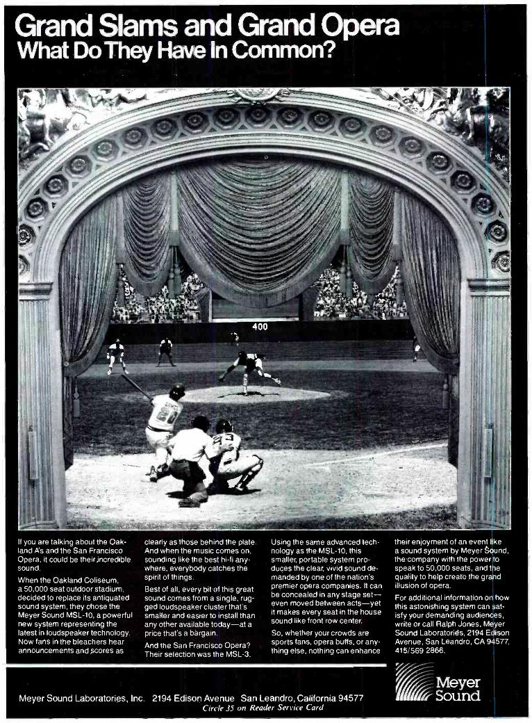
Grand Slams . ~ Grand Opera and What Do They Have In Common?
f you are talking about the Oak- land As and the San Francisco Opera, it could be their incredible sound
When the Oakland Coliseum. a 50,000 seat outdoor stadium, decided to replace its antiquated sound system. they chose the Meyer Sound MSL-10, a powerful new system representing the latest in loudspeaker technology. Now tans in the bleachers hear announcements and scores as
clearly as those behind the plate And when the music comes on. sounding like the best hi-fi any- where, everybody catches the spirit of things
Best of all, every bit of this grea sound comes from a single, rug- ged ged loudspeaker cluster that s smaller and easier to install than any other available today-at a price that s a bargain
And the San Francisco Opera? Their selection was the MSL-3
Using the same advanced tech- no|ogyastooMSL1O,/mo smaller. portable system pro- duces ,»oowac"i,iuxovnudo' manded by one of the nation o
premier opera companies. lt can be concealed in any stage set- even moved between acts-yet it makes every seat in the house sound like front row center.
So. whether your crowds are sports fans, opera buffs, or any- thing else, nothing can enhance
their enjoyment of an event like a sound system by Meyer sound, the company with the power to speak toso,00u seats. and the quality to help create the grand illusion of opera
For additional information on how this astonishing system can Sat- ist yyou,domondinyuudionoeo. write or call Ralph Jones, Meyer Sound Laboratories, 2194 Edison Avenue, San Leandro, CA 94577, 415, 569
Meyer Sound Laboratories, Inc. 2194 Edison Avenue San Leandro, California 94577 Circle 35 011 Reader Service Card
Meyer Sound
1.1FP eat!
REMOTE CONTROL AUDIO SWITCHING
MODEL 4011 - 4 CHANNEL FET SWITCH CIRCUITS
2r
Í
High speed switching Low insertion loss Full off attenuation Low distortion Balanced or unbalanced
MODEL 4088 - 8 CHANNEL MOSFET SWITCH CIRCUITS
High speed switching Jumper matrix for preset switching arrangments Dual channel op -amp for low -z sources TTL / CMOS compatibility
Switch selectable output resistors for summing applications
MODULAR AUDIO PRODUCTS
I:1
A P A UNIT OF MODULAR DEVICES. INC.
` 50 Orville Dri,e Airport International Plaza Bohemia N V 11716 15161 567-9620
( ,, ,r 2.` J)1 thit ( u;
1FudioTa 1 for P rofessionals
REEL TO REEL TAPE Ampex. 3M. All grades. On reels or hubs.
CASSETTES, C- 10 -C -90 With Agfa. TDK tape.
LEADER & SPLICING TAPE EMPTY REELS & BOXES
All widths, sizes.
Competitive! Shipped from Stock! r recording supplies catalog.
POIr corp. 312/298 -5300
1233 Rand Rd. Des Plaines. IL 60016
Circle 26 un Reader Service Card
discarded. In this sense, the output "truncation" of the multiplier result to single precision is identical to an internal A /D conversion. The common property is that of quantizing. Fortunately for the non -mathematician. the effects in the A/ D converter and in the multiplier are identical and one can therefore treat them as equivalent.
To understand the block diagram (FIGURE 3) we should add a noise source at each multiplier. The value of the noise source is approximately 1/ \/f1 of an LSB. It is difficult to prove, but we can show why it is much smaller than you would expect. Firstly. we need to add that the destruction of the low bits can be done by "rounding" rather than by truncation. Rounding means that we take the nearest available value. This means that the peak error is 1 LSB. Next we need to observe that this is the worst case error and that most of the time the error will be less. In fact, the error has an equal probability of being anything between - % and +y, LSB. The RMS value of this turns out to be 1 / 12 or 0.288 LSBs.
Limiter
noise 1<
IA) Sil
y9 G
lltl
IS)
Figure 3. A filter with noise source added to represent multiplier- truncation errors.
fo illustrate the analysis. we can re- draw the simple filter described last month in FIGURE 3. In this month's FIGURE 3, we have added a noise source after the multiplier to represent the bits discarded and we have added a limiter at the adder for large signals. Notice that the noise source is like an input signal. and we can redraw the circuit to be that of FIGURE 3B. By previous computation. we showed that the maximum output signal is given by 1 /(1 -K). Since the output signal is also present at the input of the delay (output of the adder), we now know that the input signal must not have a level greater than (I -K) if no overload is to take place. Thus, the effective dynamic range is given by the maximum signal and the additive noise.
The trade -off between limiting and noise is clear. Preventing clipping by signal reduction reduces the dynamic range just as truncation does for
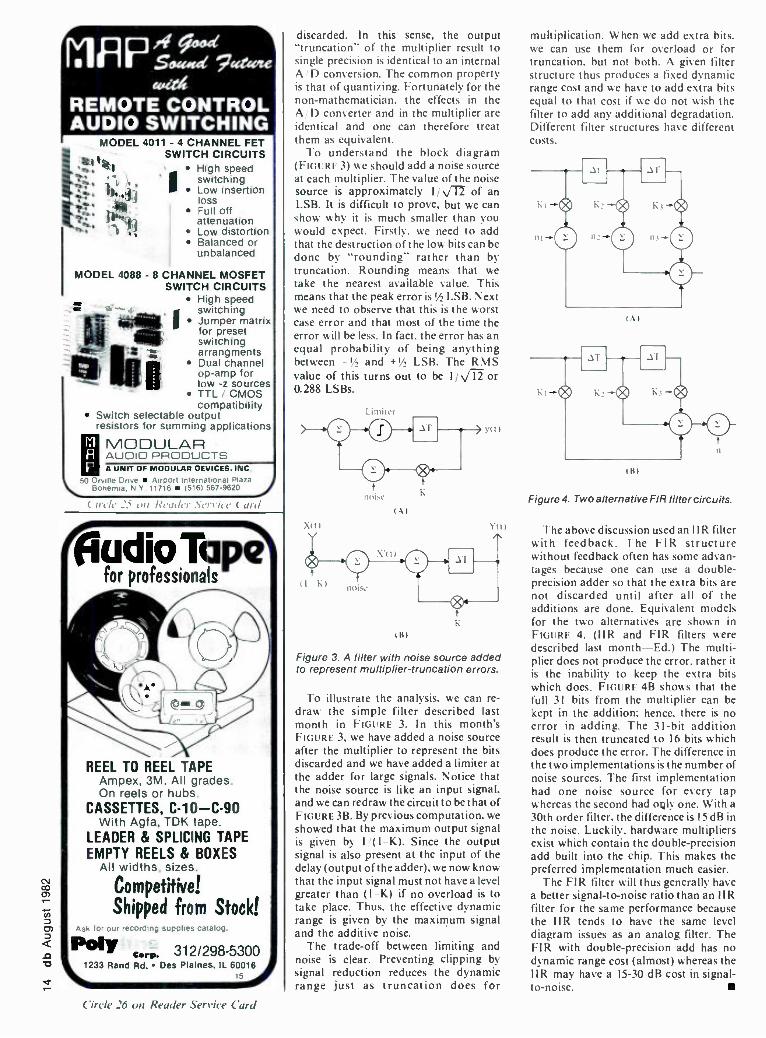
multiplication. When we add extra bits. we can use them for overload or for truncation, but not both. A given filter structure thus produces a fixed dynamic range cost and we have to add extra bits equal to that cost if we do not wish the filter to add any additional degradation. Different filter structures have different Costs.
I \I
(Al
Figure 4. Two alternative FIR filter circuits.
The above discussion used an I I R filter with feedback. The FIR structure without feedback often has some advan- tages because one can use a double - precision adder so that the extra bits are not discarded until after all of the additions are done. Equivalent models for the two alternatives are shown in FIGURE 4. (IIR and FIR filters were described last month -Ed.) The multi- plier does not produce the error, rather it is the inability to keep the extra bits which does. FIGURE 4B shows that the full 31 bits from the multiplier can be kept in the addition: hence. there is no error in adding. The 3I -bit addition result is then truncated to 16 bits which does produce the error. The difference in the two implementations is the number of noise sources. The first implementation had one noise source for every tap whereas the second had only one. With a
30th order filter. the difference is 15 dB in the noise. Luckily, hardware multipliers exist which contain the double -precision add built into the chip. This makes the preferred implementation much easier.
The FIR filter will thus generally have a better signal -to -noise ratio than an IIR filter for the same performance because the IIR tends to have the same level diagram issues as an analog filter. The FIR with double -precision add has no dynamic range cost (almost) whereas the IIR may have a 15 -30 dB cost in signal - to- noise.

The Altec Lansing 9813 High Accuracy Recording Monitor. The truth never sounded so good.
Loudspeaker accuracy. It's a
highly controversial subject. And for good reason. The most prized result of a recording session is an accurate sonic illustration of what is going on in the heads of the producer, musicians, arrangers, and composers. Recording is a process of fusion, and the monitor is responsible for an accurate painting of the completed sonic picture.
Enter our new 9813. We devel- oped it to play its highly critical part in the fusion process with great accuracy. We did it by putting nearly half a century of audio alchemy into it.
The 9813 has an all new high - frequency compres- sion driver that uses our famous Tangerine® radial phase plug.
There's a brand new network design the patent
office is already looking at, and the smooth, ac- curate highs are con-
trolled by an asym- metrical Manta -
ray® horn.
The 9813 handles power like no small monitor you've ever experi- enced. It takes on big amplifiers as
though it were addicted to watts. And if you should push it to the limit, there's a built -in system we call automatic power control,
which lowers the power (never shuts the speaker completely off) and lights a red indicator on the front panel at the same time.
The new 9813 does everything rr Altec Gorp^ration
Circle 29 on Reader Service Card
a great monitor should: It sounds super (accuracy need not be unpleasant), handles power extremely well, mids and highs adjust through very wide amplitude ranges, and its great -looking hand -
rubbed oak cabinet is small enough for even mobile record- ing vans (251/2 H x
151/2 W x 131/2 D) .
Next time you're visiting your favorite pro audio dealer, ask to hear the new 9813. What you'll hear will be the honest truth.
ALTEC LANSING'
Altec Lansing International 1515 South Manchester Anaheim , California 92803
CT

EH L-15 CO -AX 200 Watts
103 dB MIW Double Spider
15 Inch
IL For complete information call 714- 632 -8500 - 800-854-7181
EMILAR CORPORATION 1365 N. McCan St.
Anaheim, CA 92806
Circle 21 on Reader Service Card
Noise Suppression
Power Protection
Model PS -1 I he l'5-1 1..1 pottr: amiiii liming told
designed lu protect audio equipment from high voltage transients and RI- interference. Three neon lampa indicate relative phasing of the Iine. neutral and ground connections. :\ Iatrhing relay helps lu avoid amp speaker damage duc lu power up transients generated of ter a teniporrrr lus. of power. Ask your local music dealer for more details.
Linear & Digital Systems, Inc.
48 Mareo Lane. Centerville. OH
45459 (513) 4381758
Circle 16 on Reader Service Card
KEN POHLMANN
Theory & Practice
My Lunch With Beverly Waiter: A table for two? Ken: Yes. Waiter: This way. please. Ken: Well take the booth by the window. Waiter: Yes, sir. And here are your menus. Ken: You haven't said a word yet. Is there something wrong? Beverly: Nope. K: You even look depressed. What's the matter? Trouble up at the ranch? B: I'm going to quit. K: What happened? B: Album credits again. Why is it that recording engineers work their tails off for an album, putting in more hours than anybody, then get credit only if they're lucky, while their assistants never get credit? It was a closed session, I was assisting day and night for two months, and now it's released, with credits for the hair stylist, the piano tuner, the guitar pick rep, the limo driver -all them get credit, but my name isn't there. I'm not asking for points or anything -just my name in small print. But they won't even give me that. I ask you, is that fair? K: No. Was it an oversight? B: I talked to the producer. He said he submitted a complete list to the record company. But I don't care about that. It's happened too many times. How am I
supposed to get ahead in my career? Without credit, all I get out of it is the rent money and fond memories. Waiter: Are you ready to order? K: Yes, I'll have pork fried rice. B: I'd like sweet and sour shrimp -and a
strawberry daiquiri. Waiter: Anything to drink, sir? K: A bottle of dark Beck's. Waiter: Thank you. B: I've had it, I'm quitting.
K: You're leaving the studio? B: I've made up my mind. K: What will you do? B: I'll find something else. K: Are you going to give up so easily? B: Give up so easily! What do you mean? I've worked there for two years. and I still second all the time. and with the inflation rate counted in. my pay has gone down. It's a dead -end job -and I don't mean the acoustical design. K: You started out contentedly sweeping the floors. tending the archives, and doing tape dubs. Now you're angry because a gold album you assisted on didn't have your name on it. There is an advancement there. in my opinion. B: Maybe. but it's an invisible one. I
started out doing something trivial and not getting recognized for it. and now I'm doing something fairly important, and not getting recognized for that either. That's the whole story. Engineers are never appreciated. Recording is a
thankless job and I'm tired of it. K: That's a serious accusation. B: And justified too! It's a crummy job. I'll do something else for a living. K: How shall I answer? Are you really sure you've examined the nature of the problem? It's an important issue. The kind of job a person holds shapes the kind of life he leads. Do you want to know what Nietzsche said about work- ing: "Work' is the best police. it keeps a check on everyone and is a powerful restraint upon the development of reason, and the desire for self- suffi- ciency." More importantly he said: "Work forms the only law of the world - life has no other purpose. we all come into being only in order to do our share of the work, and then vanish."

B: That's great for you philosopher - types, but what about me? K: The point is that we all spend most of our lives working, and it's important to get something individually special out of the task itself. Otherwise it would be a
terrible sacrifice. Work has to be understood for what it is. And work itself is nothing. It isn't the paycheck either. its the fulfillment from the work that we must have. Only then can we overcome the restraints it places on us. B: I've already told you I get absolutely nothing special out of recording. At least you get credit for those dumb columns you write. K: Do you really mean that? B: Believe me, an engineer's job means nothing. K: A good engineer does his job because it means something to him! And he does it because he's good at it, because others depend on his work, because he enjoys doing it. B: Big deal! I get all of those things, but want more! Waiter: Fried rice and shrimp, and your drinks. Please enjoy your meal. B: It isn't enough! Waiter: I beg your pardon? B: No nothing. K: You say you're dissatisfied - you aren't fulfilled by your work. It isn't enough for you? B: No. K: A recording engineer works long
hours, and irregular hours too. You're always on call -Tuesday night, Sunday morning, it's all the same. You haven't taken more than three consecutive days off in two years. Isn't that demanding? B: Yes. K: Every time you walk into the studio, your job is new. Every client is unique and requires a different psychological approach. Every type of music is different, even every tune is different. The means and the ends for every session are different. Every time you put a micro- phone in a bass drum -even that's different every time. Don't you find that interesting? B: Yes. K: Your job is endlessly diverse and detailed. Every one of a million tasks must he tended to -everything from cleaning tape heads to doing track sheets. to the final mix which must be accounted for. Doesn't that keep you busy? B: Yes.
K: Your job is supremely contemporary. Not only does it deal with the newest artistic trends, but it encompasses the latest technological methods. Just keeping pace with new hardware devel- opments and breakthroughs in audio theory is enough to exhaust most people. Doesn't that challenge you? B: Yes. K: Your job is privileged because it's essentially creative. Everyone wants to express themselves, but how many
people ever get a chance? You go to work every day with that opportunity waiting for you. You are able to contribute to an intense artistic manufacturing process. Doesn't that excite you? B: Yes.
K: Then what's wrong? B: You make the job sound exciting. K: It is exciting. B: It is not! That's the problem. K: What do you mean? B: It's not glamorous -- it's just hard work. K: What? B: It's hard work. You forgot to mention all of the negative aspects of the things you talked about, all of the pain- in -the- butt things you have to put up with inflated egos, intense competition, broken engagements. no sleep. a candy bar instead of dinner, psychopathic people under pressure and screaming all the time -all the stupid. dumb things. K: And what job isn't like that? Did you really think you could walk in and spend all your time - as someone said -
freaking out with the stars? B: That's not what I meant. I only expect the same kind of courtesy they receive. K: What? Courtesy? B: The top dogs get all the breaks in this business. A': Listen -they have to suffer a little too. Consider superstar Beethoven - sitting there at his piano with all the strings busted because he was deaf as a stone and
A
TELEX
For Communications Behind The Scene AUDIOCOM. The closed circuit intercom for small, large, portable or fixed installations at concerts, stage productions, film or TV studios, stadiums or race
tracks, industrial or public safety applications. AUDIOCOM belt packs or wall mount stations can be "daisy- chained" by the dozens over five miles
without degradation in signal quality or strength. AUDIOCOM interfaces with other sound systems
and telephone circuits. AUDIOCOM includes headsets, mics, cables, switchboards, signalling
kits, even battery packs for remote locations; the complete intercom system for
communications behind the scene.
Quality products for the audio professional.
TELEX[:( .Fi INC 9600 Alanch Ave Su Mnnenpolu MN 55d;'u U S A
Europe Le Bonaparte -Office 711. Centre Affaires Pans.Nord, 93153 Le Blanc- Mesnu. France
Circle 20 on Reader Service Card

The Affordable
Digital Real Time Third - Octave
Spectrum Analyzer Full 30 Bands Six Memories Quartz
Controlled "Switched Capacitive Filtering" to eliminate drift Ruggedized for Road Use Microprocessor Controlled Built -in Pink Noise Source "Flat;" 'A" or "User De- fined" Weighted Curves may be employed
ROM User Curves Available.
MODEL 30 Affordable at just $1500.00
GOLD LINE P.O. Box 115 West Redding, CT 06896
(203) 938 -2588
SEND FOR COMPLETE LITERATURE:
NAME
COMPANY
STREET
CITY
STATE ZIP
Circle 14 on Reader Service Card
he beat the keys so hard they all broke - sweating out his next symphony so he could pay the rent. Finally somebody gives the poor guy a drumstick and he sits there with the stick clenched between his teeth. held down on the piano lid. so he can at least feel some kind of vibrations from his piece. It wasn't easy for him. It isn't easy for anyone who says to himself: "I need more." B: At least he got recognition! K: That's different. He was a star, you're just a recording engineer. B: What's that supposed to mean' K: Just what it says. B: It says that my job is inferior, that I'm not worth recognition! K: I didn't mean that! Waiter: Is everything allright. sir? B: Everything stinks. K: Yes, thank you. B: Then exactly what did you mean? K: What I meant was - B.' I know what you meant! You think it's a menial job, you don't know what it's like to be a recording engineer. You don't understand the kind of rewards it brings. K: You're forgetting that I used to engineer - B: Then it's been so long that you've forgotten how good it.feels. I don't know what kind of pleasure Beethoven used to get from eating drumsticks. but I know that I get a tremendous high from engineering. How do you think it feels to drive in your car and hear some song, and
It's UN- BEAR -ABLE to know you haven't subscribed to db yet!
Our rate for new subscribers is
only $10.00 and a free
sample is available
upon request.
See coupon on
reader service card.
think how familiar it sounds. then suddenly remember that you recorded it. You remember how you tried something new on the drum mics, and it sounded dynamite. You remember how the drummer put down his tracks. and left town. then someone noticed how he was off a fraction of a beat in the bridge. so you cut out a half inch of tape to bring him back on the beat -it was perfect. You remember how the producer wanted a terrible piano sound so you spent all night trying absurd things and finally used a headset mic taped to the sound board and even that still sounded too good so you had io equalize it through three parametrics. You remember how the delay line crapped out so you used a
slap machine and the band was suddenly enthralled and soon you had brought in all the studio's two track machines and had eight slaps going at once. two variable speeds per musician. You remember the big argument over the lead vocal panning. the producer's assistant had read some crazy article on perception and wanted to pan the vocals to the right so people's brains could understand the lyrics better -finally had to lock him in the lounge. You remember how an executive from the record company came down and said it was so rotten he could smell it. then a month later it was a hit. You remember all of those things. and you realize that the job is good. and that the reason you spend eighty hours a week there is because there's no other place you'd rather be. Obviously, you've forgotten all of those things. Wailer: Will there be anything more? K: I certainly hope not. Just the check. think. B: The trouble with you is. you just don't understand what it's like to be a
recording engineer. It's not a job for everyone. but a few of us wouldn't trade it for the world. K: Yes. I see your point now. B: Then please stop bad -mouthing engineers. If you don't understand the profession. ask me next time. K: One of Hemingway's characters says: "I don't have to be proud of my work. I
only have to do it well." How would you respond to that? B: Hemingway never talked to a record- ing engineer. We do it well. And we're proud of it too. Waiter: Your check. sir. B: Look what time it is! We've talked too long. K: So? B: So. I have a session this afternoon! K: I thought you were going to quit. B: What are you talking about? This is an important session. I'll get a credit for this album. Look -1 have to hurry. I have to calibrate the twenty -four track. K: Maybe I can see you later. B: What? K: Will you stop by my place when you're done? B: Take a hike.

JOHN EARGLE
Sound Reinforcement Dividing Networks
Dividing networks are used in multi - way loudspeaker systems to direct the various portions of the frequency spec- trum to their respective transducers. There are two reasons for this: we should avoid feeding signals into a transducer which cannot reproduce them, and we must avoid feeding signals into a trans- ducer which may be damaged by those signals.
Dividing networks are specified by their transition, or crossover, frequen- cies and by the slope of the roll -off be- yond the transition frequency. As a rule. dividing networks provide for level ad- justment of the high -frequency section in two -way systems and of the middle- and high -frequency sections in three -way de- signs.
High -level networks are located be- tween the output of a single amplifier and a wide -range loudspeaker system. Low -level networks perform their fre- quency division task ahead of two or more amplifiers in bi- or tri- amplified
systems. All traditional dividing net- works, whether high- or low -level, are designed so that, at the transition fre- quencies, both outputs are down 3 dB. This ensures that acoustical power out- put in the transition region will be con- stant. However, the phase relationships at crossover between adjacent sections may vary considerably, resulting in can- cellations or reinforcements in the on- axis response of the system. We will ob- serve this as our discussion develops.
HIGH -LEVEL NETWORKS A simple two -way network is shown in
FIGURE IA, and its response is shown in IB. The single reactive elements (capaci- tor C, and inductor L,) result in cross- over slopes of 6 dB /octave. At the cross- over frequency, J;,, both high- and low - pass response curves are 3 dB down (the half -power point), and the resultant phase angle between the two is 90 de- grees. The acoustical summation (power response as well as on -axis response) is
unity, as shown at IC, and the overall re- sponse is ideal. As appropriate as such a
network might be in a home hi -fi system designed for moderate playback levels, the 6 dB /octave slopes do not offer ade- quate high -pass protection for the high - frequency transducers in a sound rein- forcement system.
More commonly, we encounter a 12
dB -per- octave network, and an example of this is shown in FIGURE 2. Note in 2A that both high- and low- frequency tran- sitions make use of an L -C pair of reac- tive elements. The response, shown in 2B, illustrates sharper crossover slopes. While the response of both sections is 3 dB down at Jò, the relative phase shift between the high and low outputs is now 180 degrees, as shown in 2C. In order to compensate for this, one of the trans- ducers in the system must be connected out -of- phase, as shown in 2D, so that there will not be a cancellation in the on- axis response at the crossover frequency. When this is done, there will be a 3-dB rise in the on -axis response at crossover, due to the in -phase summation of the two 3 dB -down signals. Note in FIGURE 2A that the high- frequency transducer has been connected out -of -phase relative to the low -frequency transducer.
So far, we have dealt with pure resist- ances in our networks instead of the com- plex impedances which real loudspeak- ers present. Often, design engineers will opt for fairly complex networks in an
ßrooke Siren Systems For years our MCS200 series crossovers have been used by major touring companies
worldwide. The same high technology is available in our FDS300 series crossovers. Our products include some very unique features, highlighted below, but perhaps our best feature
is the way we'll sound with you. Available now through professional audio distributors and music stores nationwide.
24dB /Octave Slope Subsonic /Ultrasonic Filters Section Mute Control
Limiters on Each Section ±6dB Level Control Sealed Potentiometers
Brooke Siren Systems, 262A Eastern Parkway, Farmingdale, New York 11735 (516) 249 -3660 Gerraudio Inc., 363 Adelaide Street East, Toronto, Ontario M5A 1N3 (416) 361 -1667
PDS 340 wea.wc. Dva VAL..*
FDS 340
g s ems FDS320 2 -Way Stereo FDS340 3 or 4 -Way Mono
AR116 Active Direct Box MCS200 Modular Series AR125 Cable Tester 3, 4, or 5 -Way Stereo
Circle 17 on Reader Service Curd

effort to correct response anomalies in individual high- or low- frequency trans- ducers. We now present two examples of such networks. FIGURE 3 shows a two - way, 12 dB -per- octave network for a sys- tem employing a ported low- frequency section and a horn high- frequency sec- tion. Elements C1. C2. Lt, and L2 are em- ployed for the 12 dB i octave slopes. Ele- ments C3 and RI in the low- frequency circuit form a conjugate network and compensate for the increase in impe- dance with rising frequency, which is characteristic of all low- frequency trans- ducers. Such compensation results in a smoother overall impedance curve as
seen by the amplifier. In the high -fre- quency section of the network there is an adjustable L-pad. It provides for level setting, while maintaining a constant im- pedance as seen by the amplifier. The fixed T -pad introduces a predetermined amount of loss in the high- frequency cir- cuit to compensate for the basic sensi- tivity difference between the high- and
low- frequency sections (it may be as
much as 13-15 dB). The capacitor C4
boosts the high- frequency response above about 3 kHz to correct the power response of the high- frequency section.
FIGURE 4 shows another practical two - way network, one intended for higher power applications than the network shown in FIGURE 3. Here, a tapped in- ductor- resistor combination is used to adjust high- frequency level, maintaining a constant impedance as seen by the amplifier and with less internal loss (heating) than with the L -pad.
LOW -LEVEL NETWORKS FIGURE 5A shows a typical two -way
low -level dividing network in a bi-ampli- fled system. FIGURE 513 shows how two such networks may be used in tandem for triamplification. Everything stated earlier about the phase response in high -level networks applies here as well; however, because there are no circuit elements between the amplifier and the trans-
In t
EL
L.I
a
R
R
tai
Low frequency
CI - ,nfI R farads
R LI = -irk) henrys
High frequency
--t 3dB1
(+dB octane I vdBloctave
High frequency
7
90°
Frequency
On -axis summation =
7
Low frequency
IC)
Figure 1. A Simple 6 dB -per- octave dividing network. The network schematic and design equations are shown at A, and the response is shown at B. Phase relationships at crossover are shown at C.
ducers, response curves are apt to be smoother than with high -level networks.
Another advantage of multi- amplifi- cation is cleaner overall performance. Traditionally, low -frequency power re- quirements are the greatest in a sound reinforcement system, and low -fre- quency amplifiers are usually the first to go into distortion under high drive levels. With a single amplifier and a high -level dividing network, low -frequency distor- tion components will appear at higher frequencies and will be reproduced through the high -frequency part of the system. Where there is a separate low - frequency amplifier, as in a multi- ampli- fied system, any distortion generated by the low- frequency amplifier will be re- produced only by the low- frequency transducer and will likely be masked by cleaner sound from the high- frequency portion of the system.
Where there is a concern for the high- est performance in music reproduction
Input
LE
Low frequency
.7
l -dB octave
IA1
R
R
CI C'-= L'--=.17LI
High frequency --- I -3dB1
l'dB octave
fo Frequency
IBI
High High
frequency frequency
On -axis
7 summation On -axis = O summation
= 1.4
Low frequency
(C)
t'-3dB)
.7
Low frequency
(DI
Figure 2. A Simple 12 dB -per- octave dividing network. The network schematic and design equations are shown at A, and the response is shown at B. Phase relationships at crossover for in -phase transducer connection and out -of -phase connection are shown, respectively, at C and D.

ONE -INCH THE NEW
STANDARD
bs is a trademark of db.. Inc., 'ewton. MA. "ps right 1982. TEAC Corporation M merica. 77.3.3 Telegraph Rd., fontebello, CA 90640
In the world of SMPTE there are no excuses. Get it now and get it right, in sync, on time. No matter how smart your SMPTE controller /editor is, you can't work fast if the recorder can't keep up. Our one -inch 85-16B has the high motor torque and Tach rate (30 pulses per second) you need to achieve fast "lockup" and stable operation with today's new editing sys- tems. It will "park" where your controller tells it to, on the cue, every time. With the 85 -16B you only lose one track to code. Our superior control of crosstalk gives you 15 fully usable tracks for Audio! No need to waste a track as a guard band to keep code out of the mix! You get everything from the wheels to the reels: the console, the built in dbx" and TASCAM full func- tion record controls. With TASCAM, you can always get what you want without paying for extras you don't need.
In Video production you have to think big, but if you think Hard you'll see that TASCAM means business - Multitrack, Multi-image and much more. Talk to your dealer to get our equipment working on your bottom line.
TASCAM TEAC. Prcxluction Products
Circle 34 on Reader Service Card

Figure 3. A Typical Dividing Network for a Small Two -way Monitor Loudspeaker.
or reinforcement, low -level networks and multi- amplification are always called for. For many applications, 12dB -per- octave networks will provide adequate high -fre- quency driver protection. However, where extremely high output levels are expected, 18 dB -per- octave slopes may be required. As is the case with 6 dB -per- octave networks, 18 dB -per- octave net- works provide a flat summation in the crossover region; however, the total phase shift over the frequency range will be greater with the 18 dB -per- octave net- work than with the 6 dB -per- octave net- work.
Figure 4. A More Robust Dividing Network for Sound Reinforcement.
An plifier
H'gh frequency
Low frequency
Amplifier
LAI
High frequency
Medium frequency
Hear them. Write for your nearest dealer.
Circle II on Reader Service Card
CCetec Gauss
9130 Glenoaks Blvd. Sun Valley, CA 91352
Input
Low frequency
IBI
Figure 5. Low -level Dividing Networks. Connection for bi- amplification is shown at A. In the connection shown at B, net- work 1 provides the transition between the low- and mid -frequency portions of a 3 -way system. The high -frequency output of network 1 is then fed to network 2, where further frequency division provides MF and HF outputs. The two level controls provide the necessary flexibility in adjust- ing the system. Low -level networks such as shown here are normally available with either 12 or 18 dB -per- octave slopes.
Manufacturers' instructions for con- necting transducers in systems using high- or low -level networks should be carefully followed. Unless you are pre- pared to make your own acoustical measurements, this is the only way to en- sure that there will be no cancellations in crossover regions. u

z E x
Sn i4.1 1-< 9 co g2
0 LL o O
o
- iu
< a. z ,17)
(7, (flu, f
° 00 o y E
3 2 > cr >0 ct o p. > 6
O o o z cr
.; L, cc 5 Nr
LiJ I I- Li.1 o Z o z 3 z
La.1 z 1.1 cr O Z
< -J zp2,,,uo < > cr
> cc o. - 2oocu21.i Cc z ti o < o < -
< 4ln<C10 cr .TE ("Zuzi
5 - Lu . 0
UJ 7 O
..... ab OW00
Circle 27 on Reader Service Card
CLEAN DISTRIBUTION IS YOURS WITH THE
2 IN/ 8 OLT S08 DA MODULE.
OPTIMIZE YOUR MONITOR SPEAKERS. THE COMPACT S07 OCTAVE EQUALIZER IS CLEAN AND COST EFFECTIVE.
FAST RESPONSE AND EASY TO READ: THE 514 LED QUAD METER IPPM OR VU
DYNAMITE ADT AND FLANGING EFFECTS FROM A S24 TIME SHAPE MODULE.
STEREO PANNING. AUTOMATICALLY! THE S23 PAN EFFECTS MODULE.
ELIMINATE HISS WITH THE SO6 DYNAMIC FILTER/ GATE MODULE.
REMOVE LF NOISE WITH THE S05 DYNAMIC FILTER/ GATE MODULE.
SCAMPS LATEST: S25 DUAL DE-ESSER FOR SUPERLATIVE SIBILANCE CONTROL.
MUTE NOISE AND TIGHTEN TRACKS WITH THE F300 EXPANDER /GATE.
THE GREAT GATES - THERE ARE TWO IN
EACH S100 DUAL GATE MODULE.
CONTROL DYNAMIC RANGE WITH THE
SOS COMPRESSOR/ LIMITER FEATURES "SOFT KNEE" SLOPES AND PUSHBUTTON STEREO COUPLING.
THE ULTIMATE EQUALIZER! THE
SO4 PARAMETRIC WILL SOLVE YOUR MOST COMPLEX EQ
PROBLEMS.
THE VERSATILE S03 SWEEP EQUALIZER IS
EASY TO USE.
TRANSFORMERLESS SO2 MIC PREAMP WILL INTERFACE WITH LOW LEVELS.
NOT SHOWN: MODULE MINI RACK.
SCAMP POWER SUPPLY. EXTENDER BOARD. SCAMP BLANK
MODULE KITS. (AVAILABLE IN 170 8 MODULE WIDTHS.)
O g á e 7 Ire ce 10
=
.
= o Si .
.s
«ÒW R , Z 0 fa x ca. t aa, e _IQ. u t- -a
. 1.0
0 CO Z
co z - 0
V>
u, cc
a o cc
u. Z 0 <
CO CC
X ILI Ow O I-
6 FF z
I. z t o Or Ct ro u T2, t
Z
o 00 o O O

We're going to share our expertise in duplication.
We know a lot about duplication. After all, millions of our cassettes and open reel tapes are duped every day under conditions that can make you hopping mad. So, we had to learn how to make cassettes that sound terrific, last, and are as trou- ble free as possible.
Maxell gives you the cassettes you need, with the quality you must have. Tipe ends stay anchored. Our shells have a five screw construction to eliminate warping. Maxell devel-
oped a four- function leader with A/B side indications, directional arrows, non- abrasive head cleaner and five- second cue to set timing and level. In performance, highs are clear and lows are solid and pleas- ing. On the business side, supplies are delivered when you need them. What more do you need to know about duplicating cassettes? Call us, we'll give you the name of your nearest Maxell distributor, quick as a bunny.
maxell. PROFESSIONAL/ INDUSTRIAL DIVISION
Our success is magnetic.
Maxell Corporation of America, 60 Oxford Dr., Moonachie, N.J. 07074 (201) 440 -8020
Circle 19 on Reader Service Card

'w» » Editorial
All- purpose Audio
"An all- purpose hall is a no- purpose hall." Cyril M. Harris
HWN 7 HAT FOR a short course in architectural acoustics? The noted acoustician was so quoted in a recent article in Discovery magazine. and although the above doesn't quite give you every-
thing you need to know about room design, it gives you enough to get started.
Professor Harris deals in large volumes (Lincoln Cen- ter and such), but his words apply to halls (and studios) of any size. from the Mormon Tabernacle to the garage - size operation in the backyard. As for the latter, a large infusion of cash will not turn it into the former. although people continue to try. You can certainly make a small room look spectacular; sliding glass doors, curtains, exotic wood surfaces, a brick wall here and there, and of course a classy carpet on which to spill coffee. All this is
very nice -your studio will look delightful, feel com- fortable, and sound like....
It will probably sound like just what it is -a small studio. There's certainly nothing wrong with this, unless you've just been separated from your inheritance by some soothsayer who has promised you Carnegie Hall in a shoe box. If you've really done your homework, you shouldn't be plagued with slap- echoes, strange room modes, and other little quirks, but Symphony Hall it's not, and you shouldn't expect it to be. Symphony Hall takes space, and lots of it. If your favorite acoustical guru tells you otherwise, become someone else's disciple fast.
After considering the price for enclosing a lot of air within four walls, you're probably thinking of building (or already have built) a small -to- medium size studio. Given the realities of the recording industry, anything more expansive/ expensive is probably impractical any- way. So, if there's spare money lying around, it should probably be invested in quietness, rather than splurged on multi -purpose acoustics (whatever that is).
As we step tentatively towards digital technology, dynamic range gets expanded, and a lot of this expansion is downwards. That makes it easier to hear the studio air conditioner, and the plumbing down the hall. For the moment, our pressing plants will probably make sure that none of these sounds intrude on the listener, but every now and then a quiet one does slip through the QC department unnoticed.
Given the various digital -disc systems that are anxious to take over the consumer audio market, the day may
very well come when acoustic noise reduction becomes as important as electronic noise reduction. In other words, give more serious thought to the single purpose of silence, and less to concocting a studio that will do everything.
Needless to say, this little dose of Harris -inspired reality therapy will not placate all patients. We've seen many musicians, producers -even engineers! -prowl about the stages of large concert halls (ironically, some designed by you- know -who), trying to transform them into various other things, including a rock- and -roll studio. About the kindest thing to be said here is that some of these attempts are not as disastrous as others. Provided the above -mentioned visitors are relieved of their power tools upon entry, the halls may be expected to go on for years more, doing well at what they were designed to do, if not everything else.
Well then, how best to hear the sounds recorded or reproduced in your single- purpose hall? By no small co- incidence, this month's issue takes a look at some of the variables that go into speakers and the rooms into which they are placed. So perhaps we should paraphrase Harris and say that, An all- purpose -speaker is a no- purpose speaker." Or how about. "An all- purpose X is a no- purpose X." Let X = microphone, console, speaker, hall, whatever. Now, depending on X, you may or may not go along with the quotation. Helping in the vote is the fact that microphones are easy to swap around, and consoles are not.
Speakers? They're certainly not impossible to change. but it is difficult. Usually, the house speaker is designed into the room (one way or another), and it's a nuisance -- and a backache -to make frequent changes. So, we make do with one system, which becomes our own all- purpose speaker.
We're accustomed to our microphones having "per- sonalities," and we carefully choose the right one to compliment the sound source. Perhaps we should look for a speaker that has no personality whatsoever, so as not to color our judgement of the everything -else in the signal path.
Now, if someone will just build such a speaker. And then we'll need someone else to recognize it as such. Once this is done, we'll buy a pair, and put them in our all - purpose listening room. JMW

ROBERT R. HARVEY
The Venerable 604 Author Harvey has painstakingly researched the history of the 604 to bring us this entertaining and informative look at one of the most widely used studio monitor.
SIXTY -FOUR PERCENT of American recording studios currently offer as a monitor, or a component thereof, a loudspeaker driver first introduced in 1943. That 40 year -old driver is the Altec 604 duplex loudspeaker -
actually two drivers, a fifteen -inch woofer and compression horn, mounted coaxially. The 604 is employed in the following systems: in custom installations, in Altec cabinets, in Audio - technics Red Series monitors, retrofitted with the Mastering Lab crossover, Time -Aligned® in UREI monitors, or Time - Sync d® with an Audiotechniques crossover. Why is an ancient duplex driver so prominently favored by the modern state -of- the -art recording industry?
IN THE BEGINNING Before there ever was an Altec Corporation, in the 1920s and
1930s there was Electrical Research Products, Inc., a division of the Western Electric Company. At that time, like today, Western Electric/ Bell Labs represented the cutting edge of technological advancement and scientific discovery in many areas. One such area, the focus of E.R.P.I., was that of the design and manufacture of premium quality sound recording and playback equipment.
In 1938. by consent decree, the federal government forced Western Electric to divest itself of E. R.P.1. and other divisions. The telephone maker was falling behind on orders for military communications equipment and needed to concentrate its energies and resources in those areas. Knowing a good thing when they saw one, a group of E.R.P.I. engineers purchased their orphaned division and proceeded with business as usual under the name of All Technical Products, shortened by acronym a year later to Altec. In 1941. the Altec Corporation came to the conclusion that the world was ready for a superior studio loudspeaker.
THE CHALLENGE Altec was dissatisfied with the so-called fine hi- fidelity
speakers of the day, deeming them inadequate for use in the recording studio (and the living room as well). The criteria on
Robert Harvey is a freelance writer specializing in radio N and television broadcast communication arts.
which were based judgments of adequacy reflect the recording standards of the time. and are as follows: Size: the monitor must fit comfortably in the typical walk -in
closet -size control room. Focusing: the monitor must focus. i.e.. the drivers must blend
together at the close range at which it would be employed. typically 5 feet.
Efficiency: 105+ clean dBs must be obtainable from the largest quality amplifier available at that time -25 watts.
Fatigue: distortion must be low enough that fatigue does not overcome the studio staff after hours of listening.
Sensitivity to room placement: the monitor must sound rela- tively the same in any typically irregular space in which it might be used, both for the benefit of the studio and the reputation of the monitor.
Reliability: the monitor must endure 12+ hours of continuous operation. open mics falling into the drum kit, the operatic soprano, the bumbling studio assistant.
Consistency: the monitor must not differ sonically one to the next.
Dispersion: the monitor must have a wide enough dispersion field to encompass engineer, producer and client.
Accuracy: the monitor must have a frequency response from 50 -60 Hz to 4 kHz, rolling off to -IO dB at IO kHz. No monitor at the time satisfied all nine criteria.
A STAR ARRIVES IN HOLLYWOOD On October 20, 1943, at the Hollywood Technical
Conference of the Society of Motion Picture and Television Engineers, James B. Lansing, one of three Altec engineers who had been working on the monitor project, presented the world with the Altec 604 Duplex loudspeaker. From two years of research and development came a loudspeaker that for the first time satisfied all nine criteria for a desirable studio monitor. It was six cubic feet compact and able to produce 103 dB at I watt and I meter. It was not especially sensitive to room placement, and was nonfatiguing, highly reliable and admirably consistent. Dispersion was 60 degrees- adequate. Accuracy and resolution were impressive for the day, equalling or surpassing all others. Bandwidth followed the "ideal" curve, although there was some roughness in the 1 -2 kHz crossover region and there was a 4 -6 dB rise in response from 2 to 4 kHz.
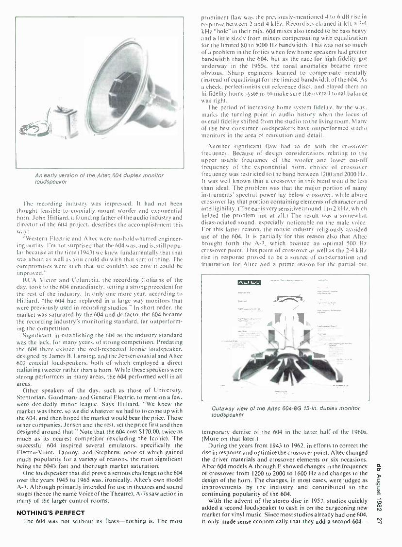
An early version of the Altec 604 duplex monitor loudspeaker
Ehe recording industry was impressed. It had not been thought feasible to coaxially mount woofer and exponential horn..lohn H illiard, a founding father of t he audio industry and director of the 604 project. describes the accomplishment this way:
"Western Electric and Altec were no- holds -barred engineer- ing outfits. I'm not surprised that the 604 was. and is. still popu- lar because at the time (1943) we knew fundamentally that that was about as well as you could do with that sort of thing. The compromises were such that we couldn't see how it could be
improved." RCA Victor and Columbia. the recording Goliaths of the
day, took to the 604 immediately, setting a strong precedent for the rest of the industry. In only one more year. according to Hilliard. "the 604 had replaced in a large way monitors that were previously used in recording studios." In short order.-the market was saturated by the 604 and de facto, the 604 became the recording industry's monitoring standard, far outperform- ing the competition.
Significant in establishing the 604 as the industry standard was the lack, for many years. of strong competition. Predating the 604 there existed the well -respected Iconic loudspeaker, designed by James B. Lansing. and the Jensen coaxial and Altec 602 coaxial loudspeakers, both of which employed a direct radiating tweeter rather than a horn. While these speakers were strong performers in many areas, the 604 performed well in all areas.
Other speakers of the day, such as those of University, Stentorian, Goodmans and General Electric, to mention a few. were decidedly minor league. Says Hilliard. "We knew the market was there, so we did whatever we had to to come up with the 604, and then hoped the market would bear the price. Those other companies, Jensen and the rest, set the price first and then designed around that." Note that the 604 cost $170.00. twice as
much as its nearest competitor (excluding the Iconic). The successful 604 inspired several emulators, specifically the Electro- Voice, Tannoy. and Stephens, none of which gained much popularity for a variety of reasons, the most significant being the 604's fast and thorough market saturation.
One loudspeaker that did prove a serious challenge to the 604 over the years 1945 to 1965 was, ironically, Altec's own model A -7. Although primarily intended for use in theatres and sound stages (hence the name Voice of the Theatre). A -7s saw action in many of the larger control rooms.
NOTHING'S PERFECT The 604 was not without its flaws nothing is. The most
prominent flaw was the previously- mentioned 4 to 6 dB rise in response between 2 and 4 kHz. Recordists claimed it left a 2 -4
k Hz "hole" in their mix. 604 mixes also tended to be bass heavy and a little sizzly from mixers compensating with equalization for the limited 80 to 5000 H7 bandwidth. This was not so much of a problem in the forties when few home speakers had greater bandwidth than the 604, but as the race for high fidelity got underway in the 1950s. the tonal anomalies became more obvious. Sharp engineers learned to compensate mentally (instead of equalizing) for the limited bandwidth of the 604. As a check, perfectionists cut reference discs, and played them on hi- fidelity home systems to make sure the overall tonal balance was right.
The period of increasing home system fidelity, by the way. marks the turning point in audio history when the locus of overall fidelity shifted from the studio to the living room. Many of the best consumer loudspeakers have outperformed studio monitors in the area of resolution and detail.
Another significant flaw had to do with the crossover frequency. Because of design considerations relating to the upper usable frequency of the woofer and lower cut -off frequency of the exponential horn, choice of crossover frequency was restricted to the band between 1200 and 2000 Hz. It was well known that a crossover in this band would he less
than ideal. The problem was that the major portion of many instruments' spectral power lay below crossover, while above crossover lay that portion containing elements of character and intelligibility. (The ear is very sensitive around Ito 2 kHz, which helped the problem not at all.) The result was a somewhat disassociated sound. especially noticeable on the male voice. For this latter reason, the movie industry religiously avoided use of the 604. It is partially for this reason also that Altec brought forth the A -7, which boasted an optimal 500 Hz crossover point. This point of crossover as well as the 2 -4 kHz rise in response proved to be a source of consternation and frustration for Altec and a prime reason for the partial but
ALrEc
Cutaway view of the Altec 604 -8G 15 -in. duplex monitor loudspeaker
temporary demise of the 604 in the latter half of the 1960s. (More on that later.)
During the years from 1943 to 1962, in efforts to correct the rise in response and optimize the crossover point, Altec changed the driver materials and crossover elements on six occasions. Altec 604 models A through E showed changes in the frequency of crossover from 1200 to 2000 to 1600 Hz and changes in the design of the horn. The changes, in most cases, were judged as improvements by the industry and contributed to the continuing popularity of the 604.
With the advent of the stereo disc in 1957. studios quickly added a second loudspeaker to cash in on the burgeoning new market for vinyl music. Since most studios already had one 604, it only made sense economically that they add a second 604

one of the same is cheaper than two of practically anything else. With two speakers in every studio and the new medium being stereo, there arose a new criterion of monitor adequacy: imaging.
Paired loudspeakers must produce a strong and stable stereo image. Would the 604 pass this test? As it turned out, those studios that brought a second 604 for economic reasons were not disappointed. Coaxial and duplex loudspeakers proved to be the world champs of imaging simply because they closely approximated a point source of sound -very important to stereo. But remember, the duplex construction of the 604 was chosen 15 years earlier for the sake of close range focusing, not stereo imaging. That's called serendipity, and the mono standard became the stereo standard.
WATCH OUT, MR. ALTEC In the years following the advent of the stereo disc, record
sales grew dramatically, as the luscious sound of stereo captured the fascination of the modern consumer. To keep up with the voracious appetite for "musical product," the recording industry witnessed the christening of many recording studios. Then came the Beatles and other highly successful new groups. and record sales grew even more dramatically. Recording studios continued to multiply. Naturally. manufacturers of recording studio equipment were eager to find ways to capitalize on the new need for their products.
In the mid -60s, one brave company, JBL, for many years in the professional sound reinforcement market, decided to step into the monitoring ring with the 604, hoping to knock it out or at least score high points and make some money selling monitors. The JBL 4300 series monitors were not quite as
efficient as the 604 but could handle more power and thus play louder. They extended in response from 30 Hz to 20 kHz (some of the 4300 series monitor extended only to 15 kHz) -quite a bit better than the 604 could do. Manufacturing consistency was good and they were very rugged. Close -range focusing did not measure up to that of the 604, but as control rooms were getting larger, this criterion decreased in importance. Imaging ability did not measure up either, as duplex mounting of drivers was very hard to beat. And although many detractors disputed the 4300 series accuracy, the sound heard on the JBLs did correspond more closely with that of home systems than did the sound heard on the 604. The primary reason for this was the J BL's extended frequency response and absence of a 4-6 dB rise in response between 2 to 4 kHz.
Backed by competitive pricing and an already established sales force, the 4300 series monitors offered a serious challenge to Altec's established 604. It is unfortunate that detailed sales figures are not accessible to chart the progress of JBL's incursion into 604 territory. Nevertheless, sources close to the studio industry in the mid and late sixties report JBL monitors replacing the 604 in a significant number of studios. This JBL onslaught marked the end of the 604's undisputed reign, and in proving the 604 not invincible from a marketing standpoint, opened the door to future challenges. But the 604 wasn't finished yet.
A STROKE OF LUCK Despite the popularity of theJBL monitors, it could hardly be
said that the 604 was taking a licking, although it was certainly staggering a bit. It was apparent that something would have to be done to the 604 to maintain strong market position, and something was done -only not by Altec, and quite by accident.
Doug Sax had been operating the Mastering Lab in Hollywood. In settlement of a cash debt owed him by a
mastering client, Sax accepted an amplifier and a speaker in a
ported walnut box. The speaker was a 604. "I took the 604 home -1 needed an extra speaker at home -and I couldn't listen to it. I went crazy with it. On my own, I built a very simple crossover for it, following the advice of my brother Sherwood - just a simple 6 dB per octave crossover -and 1 put the thing on and I found that it made it somewhat listenable. It wasn't flat, it wasn't accurate, but the quality which basically drove me crazy
in the speaker (the 4 -6 dB rise from 2 to 4 kHz) had been removed.
"I went back to my brother and I said. 'Hey, this doesn't sound that bad.' and he said, 'Well, you can't listen to a violin on it.' -he had never liked the speaker -and I said 'Yes. you can listen to a violin on it. it's not bad at all.' And he said. 'Well, that's very interesting. - Intrigued, Sherwood took the 604 to his lab and developed a crossover for it that (I) had lower distortion than the one supplied by Altec, (2) boosted the low frequency response to 40 Hz, (3) boosted high frequency response to 15 kHz, and (4) flattened to a noticeable degree the 2-4 kHz peak that had been the object of much criticism.
"The speaker [with Sherwood's crossover] actually measured pretty damn flat under outdoor conditions. So my brother said. 'Take this home and see what you think.'So I took it home and I
said. 'That sounds fairly respectable -it's not terrific but it's fairly respectable.' And he said, You know, there's all these studios around town with 604 -E's and they're having trouble with them because they don't really relate to a home system. Why don't we make up a few of these and you take them to the studios and let them put 'em in place of their crossover and see
what they think.' Which I did. and at that time they started to put them into service."
Dubbed the Mastering Lab Crossover, it met ready and eager acceptance at many recording studios because it brought the 604 into closer correspondence with home speakers while retaining the desirable qualities of the 604. Also. a pair of M L crossovers cost less than a new pair of monitors. The Sax brothers produced their crossover for about a year, at which point they decided to sell the design. It had become more trouble to them than they felt it was worth. the trouble being caused by studios with speaker, room interface problems. Such problems could not be helped by the Mastering Lab Crossover, and so it was out of ignorance (acoustic design was not widely understood then) that the owners of these studios called Doug Sax to complain that his crossover wasn't working. Sax found himself having to journey to the studio to lend a hand and clear his reputation.
"If it was something that you would ship out and never hear from them again, and charge whatever you were going to charge, it'd be terrific. But instead you were getting into acoustical design and room treatment which was not an area in which my brother or I wanted to spend time, and it was interfering with the operation of my prime business which was the Mastering Lab. We wanted to get out of it real fast." The ML crossover design was first offered for sale to Altec in 1971. John Eargle, then in charge of Altec's Professional Division (and later with JBL), was eager to obtain the crossover in order to keep the 604 competitive with JBL's 4300s. But Altec higher - ups declined the offer on grounds, says Eargle, "that the ML network did not live up to all they thought it should. They didn't feel it was substantially better than their own and didn't feel it would be all that significant a factor."
The next offer went to Audiotechniques of Stamford. Connecticut. Audiotechniques was a young studio design, sales
and consultation firm, and well suited to handle the kinds of problems of which the Sax brothers were attempting to rid themselves. The deal went through in the form of a licensing arrangement with Audiotechniques paying a royalty on each crossover sold.
In addition to offering the ML crossover as a retrofit item, Audiotechniques included it as standard fare in their Red Series monitors, the Big Red and the Super Red. The Big Red monitor placed a 604-E2 in a sealed, 6 -cubic foot, Capital Records - designed enclosure. Response with the ML crossover was 40 Hz -to -17 kHz, ±2 dB, and although efficiency was the same as a
stock 604, maximum sound pressure level was about 4 dB greater due to the increased power handling of the 604 -E2. Manufactured by Altec exclusively for Audiotechniques. the E2 utilized extra -rugged driver materials to achieve the 2 -to -1
increase in power handling. The Super Red was a sealed, 12-
cubic foot Sax brothers design employing in addition to the 604-E2 a I 5-inch low bass woofer crossed over at 100 Hz. Super
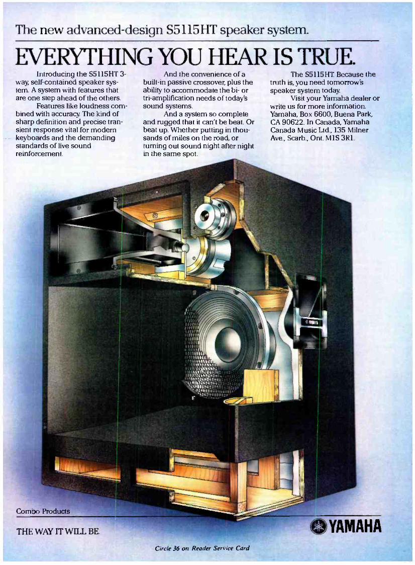
The new advanced -design S5115HT speaker system.
EVERYTHING YOU HEAR IS TRUE. Introducing the S5115HT a-
way, self -contained speaker sys- tem. A system with features that are one step ahead of the others.
Features like loudness com- bined with accuracy. The kind of sharp definition and precise tran- sient response vital for modem keyboards and the demanding standards of live sound reinforcement.
And the convenience of a built -in passive crossover, plus the ability to accommodate the bi- or tri- amplification needs of today's sound systems.
And a system so complete and rugged that it can't be beat. Or beat up. Whether putting in thou- sands of miles on the road, or turning out sound night after night in the same spot.
The S5115HT. Because the truth is, you need tomorrow's speaker system today.
Visit your Yamaha dealer or write us for more information. Yamaha, Box 6600, Buena Park, CA 90622. In Canada, Yamaha Canada Music Ltd., 135 Milner Ave., Scarb., Ont. MIS 3R1.
Como Products
THE WAY IT WILL BE. YAMAHA
Circle 36 on Reader Service Card

o
Red frequency response mimicked that of the Big Red, but because of the extra driver, it handled more power and had tighter bass response.
Mastering Lab crossovers and Red Series monitors were well received by the studio industry, no doubt providing Altec some discomfort. Sales grew to such a point that in 1975 Audiotechniques had to establish a subsidiary company, Audio Marketing Ltd., to handle the tasks of manufacturing, marketing, and so on. especially for those items. Again, it is
regrettable that detailed sales figures are not available: however. Audiotechniques reports 1000 pairs of ML crossovers. 500 -600 pairs of Big Reds and 60-70 pairs of Super Reds sold between 1971 and 1981. the year production ceased.
JBL was probably not too fond of Doug Sax and Audio - techniques. With the introduction of the ML crossover, many studios found no need to switch to JBL, as there was no advantage in doing so. and were happy and relieved to be able to stick with their old friend, the 604. (JBL prospered nevertheless because of the huge growth of the studio industry from the late sixties to mid seventies.)
ENTRENCHED The strong popularity of the ML's 604s underscored the
studio industry's general preference for that driver. Preference is the key word here, alluding to the fact that sonic performance was not the only reason for the 604's solid following. There were other reasons of a more intangible nature.
Over the years from 1943 to the late sixties, almost all engineers and producers became intimately familiar with the 604. The 604 represented a commonly- shared "experience " -a point of reference. It offered proven and predictable results. making it difficult for aspiring monitors of whatever high caliber to break into the market. Additionally, aural accli- mation helped entrench the 604. With ongoing exposure to any given high -quality loudspeaker, the ear will, in time, acclimate to the sound of that loudspeaker. When that happens, nothing else sounds "right." If one considers that prior to the late 60s. almost all engineers and producers worked day in and day out with the 604. as did a good many after that, it becomes apparent that acclimation has played some part in the continued popularity of the 604.
ONE MAN'S OUEST M. T. "Bill" Putnam, a founding father of the modern
recording industry and eminent innovator in the field of recording studio techniques, electronics and acoustics, had never particularly cared for any of the available recording monitors. finding them wanting in a variety of ways. His ears were always open for something better. As owner of three successful recording studios, United and Western in Los Angeles and Coast in San Francisco, Putnam had a stake in a
sonically more accurate monitor -more and steadier business. This cause -and -effect relationship, while valid in theory was in actual practice upset by a certain phenomenon. In Putnam's words, "There has never been a time in all the thirty years I've been in the recording business that we haven't gone through cyclic changes in terms of monitors -today one thing, tomorrow another. But the 604 has always been right in there.
"In the mid sixties to late sixties, JBL began to make a
significant move and by the early seventies we could see cyclic changes away from the 604 to the JBL sound.At that time, we (United, Western & Coast) were vacillating between the 604 (Mastering Lab) and JBL. In a period when more and more independent producers started to arrive on the horizon you found yourself [the studio owner] at the mercy of the independent producer and guest mixer who were then imposing their own personal choices in terms of the monitoring system you used." A tenuous situation existed. It was unclear as to what constituted a "better" monitor in such a fickle market. Unclear, that is, until Putnam made the following observations:
"About 1976 we were, as usual, constantly going through these [monitor] changes and [were] in the process of evaluating monitoring systems as we always were.... Many people who
The Altec 604-8K monitor loudspeaker
had grown up on the 604 sound may be temporarily changed over to the JBL monitors and then invariably some of the diehards would go back to the Altec 604 sound. Then, for the 604 advocate, along came the Mastering Lab Network, which was a significant step forward. and later the Super Red. At that stage of the game (1977). I really felt that we had had enough consensus. I think that we were ready to go with the 604." Putnam's observation is testament again to the 604's reclamation of popularity via the Mastering Lab Crossover after the onslaught by JBL. At one of his studios in particular, he found his clientele almost unanimously preferring the Master Lab 604.
These circumstances triggered the design of a new and improved monitor, which was built and installed around mid- year 1976. Nicknamed the "Big Bertha," she resembled the Super Red, being a I2 -cubic foot cabinet holding the 604 and a
I5 -inch woofer, but differing in five major ways:
I) The cabinet was resistively vented, thereby reducing low band distortion four fold while retaining the transient re- sponse of a closed box.
2) Woofer and 604 were moved closer together for smoother, lower midrange response.
3) The sections of the quasi -sectional horn were sawed out to reduce transient distortions.
4) The crossover was designed by Putnam for a response. as
extended as, but smoother than, the Super Red. 5) Efficiency was lower because of resistive venting.
Big Bertha was greeted with much enthusiasm by mixers and producers but she lasted only a very short time, for even as she was being installed and fine tuned, a fateful redesign was under way.
ANOTHER MAN'S QUEST Ed Long, a respected speaker designer for 21 years, had
always been looking for ways to build a better speaker. That's how he makes his living. For some years, Long had been aware of the potential for sonic improvement of multiway systems held in the strict planar alignment of driver acoustic centers. It had been known since the 1930s that gross misalignments were to be avoided, but as to the audibility of small misalignments there existed throughout the industry considerable controversy and confusion. Little realistic investigation had been published in the area of acoustic center offset correction because the problem was not well understood and because correction methodologies were either imprecise, very tedious and time consuming, or required very expensive instrumentation and computer processing. To make matters worse, such methods were clumsy: run some tests, move a driver, run some more tests, move the driver a little more. etc.
Curious as to the actual degree of improvement able to be realized through time offset correction -he had never heard a
properly offset -corrected system, as none were available -Long was determined to find an accurate, expedient, and cost - efficient methodology. With some assistance from Alembic engineer Ron Wickersham, Long tackled the problem.

This Is
Bob Ludwig.
He Is The Engineer Behind The Disk Mastering Of Over One Hundred Platinum And Gold Albums And A 1981 Grammy Award Winner.
Bob Ludwig Masters Disks and Cassettes Exclusively on Agfa Tape.
AGFA AUDIO
MAGNETIC TAPE DIVISION
The Mastering Choice of the Masters.
Mr. Ludwig accepts no compensation for his endorsement.
Circle 31 on Reader Service Card

0
Introducing the audio processor that remembers.
Super f rii e Time
The first Microprocessor -based special effects device. It has non -volatile memory storage for special effects .. .
recalls them on command ... in the studio or on stage. Now, with Lexicon's Super Prime Time digital delay - the
first programmable, microprocessor -based audio processor - recall the desired
as well as have a
at all delay settings .
processor like it.
opens a whole new
you can create ... store ... and effects for any given piece of music,
frequency response of 20 Hz to 20kHz There's never been an audio
For the performer, Super Prime Time world of virtually unlimited musical enhancements. This
remarkable system stores 8 factory preset programs and 32 user programs of effects ... recallable at any time.
Programs may be off -loaded to audio tapes or cassettes providing unlimited off -line storage.
Super Prime Time. The first microprocessor -based delay.. the audio processor that remembers.
Write for full details today.
programmable digital delay processor
INVENT 1 7 10 KN.
w i I OVID
30'. 34 .
VLIMIr -
pwlK MAIN AUX AFB
To N a
IOKC. KOaNCUUT.
INPUT MIX
/11's
' \ ' MANUAL -
- WIMP l IVA XLI
..O
. I _ "P"
p LiCA T
.. . -
"LAY -2"""":
OFN A
á
l 6 6 7
MAIN AUX A wuT O 0U11CI
OUTPUT MIX
SUPER PRIME
INY WM CA T
e. oN. mop q, IITAL VCA o0 In alv
aa , ouT
.0e RATO
vco
Lexvo,,zuner Street, Waltham, MA 02154/(617) 891-6790 /TELEX 923468 Export: Gotham Export Corporation, New York, NY 10014
ci NFS:, Circle 18 on Reader Service Card

00
32 BRG FCJ rt'CM,22 L.OAO UP Oii F¢LT ATTACH ITEM 17 TO ITEM 10, RED TO POSrtIVE, 9LNLK TO NEGATIVE.
LOCATE Cr NTER VOCE COIL wINOING AT CENTER OF TOPPLATE THICKNESS.
CEMENT Eri) 0 WITH OED wTH .
ASSEMBLE /7( WITH \ AND ADD POWER MAO
COAT ENTIRE 5',iRROUD YNT MIKED :VT wITM IS% Se.
SOLDER (3 TO ® WITH. O CEMENT ITEMS n 2 O® WITM ®,
ITEMS IL 7 B M NOT SHOWN FOR CLARITY. LEMENT 2 WITH U. CEMENT I lDOM) WITM O k ©,
MRS. UM]SS mHt*MSU SKCIYIO)
CED
Assembly chart for a ceramic magnet duplex
developing unique instrumentation which enabled him to see
the effects of parameter adjustments (positioning of speaker and altering of crossovers) or the amplitude time vs frequency characteristics of a loudspeaker system as the adjustments were being made.
Long put his instrumentation to the test. After aligning several systems and checking the results by ear, he came to the conclusion that the tool, in the hands of a skillful operator, significantly improved the sonic performance of multidriver systems.
With such an elegant tool in hand, the next step was to find a
client -to get the word out that he could quickly and cost - effectively improve the sound of a loudspeaker. To this end, Long presented before the 54th Convention of the Audio Engineering Society, in May 1976, a paper describing his new Time Align Technique.
FORCES UNITE Bill Putnam saw Long's paper and became fascinated with
the concept of time alignment, not only as a student of loudspeaker design, but as a studio owner looking to improve the
604. Big Bertha had just been installed in the soffits, but Putnam was still eager to improve it. Jim Cunningham, working for Putnam at the time as director of Technical Facilities, and being
an old friend of Long, arranged a meeting between the two. The meeting took place in Los Angeles, where it was agreed that Putnam would come to' Long's lab in Oakland for a
demonstration. At that demonstration, Putnam became a
believer: "I recall a demonstration in which [Long] demonstrated two
systems that had the same amplitude response but in which the time offset in one system was 0.45 milliseconds and the other system virtually zero. On the male speaking voice, it was the

most phenomenal demonstration that I can recall hearing. and that's when I became convinced. The clarity and realism I heard on the time -aligned system was remarkable. On some other program material. I wasn't nearly as conscious of it as I was on this one very dramatic demonstration."
Putnam returned to l.os Angeles excited about correcting the time offset of his Big Bertha. and shipped to Long a 604 in a
utility -grey Altec cabinet for offset correction. The correction was made. not by moving the drivers but by delaying the signal to the woofer by 0.45 milliseconds with a passive crossover. Putnam then compared this time -aligned crossover to his Big Bertha crossover: time -aligned won hands down. (Interestingly. while no attention was paid to time offset correction in the design of the Big Bertha network. by serendipity her network delayed the signal to the woofer by 70 percent of the time - aligned value.) Time -align networks were installed in the Big Berthas and the response from mixers and producers as well as artists was very positive.
Up until this point. Putnam. the studio owner, was interested only in bettering the 604 to please his clients. But then Putnam. the manufacturer. owner of United Recording Electronics Industries (UREI). began to speculate.
"We were not in the speaker business and had no great desire to be -UR E I was in the black box signal processing business- and the project came about as an answer to the needs at the studio. What appealed to me was the possibility of getting some synergism from the techniques Ed had developed and the general industry swing back to the 604." Believing that there was some money to he made. Putnam hired Long as a
consultant to design an off -the -shelf time -aligned 604 monitor the URFI 813TA monitor.
The 813 houses the 604 and 15 -inch woofer in a 12 -cubic foot cabinet. Reflex loading was chosen for low distortion and high efficiency. although some of the efficiency was traded off for better low frequency transient response. A custom plastic horn was substituted. It had no sections (like the Big Bertha) and was longer for a lower cutoff frequency. The time -align network aligned the crossover points in the time domain and featured level controls for the midrange and high -frequency horn drivers. Protection circuitry. consisting of speaker fuses and a
tiny light bulb acting as a fuse and indicator of driving level, was included.
The 813 was built and installed in several of Putnam's control rooms and for about six months he gathered opinions and reactions to the monitor. Response was overwhelmingly favorable. As a final marketing test, Putnam demonstrated the 813 at the 56th Convention of the Audio Engineering Society in May of 1977. The reaction of those in attendance was so enthusiastic that the decision was made to put the 813 into production.
Sales were explosive. In the following year, the 811 was introduced employing the 604 by itself in a 5 -cubic foot bass reflex cabinet. Response was 80 to I5 kHi. ±3 dB. A year later. the 815TA was introduced. It differed from the 813 in that it occupied 13 cubic feet of space. employed two 15 -inch woofers. and could handle more power.
It is thought that. to date, in excess of 2000 Time Align monitors have been sold. Some sources have stated that in two year's time, by 1979, the 800 series monitors had become the accepted standard for advocates of the 604. making converts of many and bringing stray lambs back to the fold. According to Bill Putnam, "The success was far beyond anything we had anticipated. For a company that's not in the speaker business. we sell a lot of speakers."
UNNOTICED EFFORTS It is interesting to note that in the same year that Ed Long
time -aligned the 604 for UREI, John Meyer time- offset- corrected a 604 for McCune Sound in San Francisco, less than 15 miles from Ed Long's Oakland lab. Meyer had been correcting loudspeaker systems for time -offset for several years using computer analysis. active crossovers, and delay lines. without much notoriety. The Meyer, McCune 604 also suffered
a lack of notoriety primarily because it was pressed into service as a stage monitor. It is ironic that although Meyer did try to interest manufacturers in his 604 crossover, they all told him it wouldn't fly. If only he had made some up. and taken them to the studios in town.
SCRAMBLING TO KEEP UP
The huge success of the UREI time -aligns took the industry, and in particular Audio Marketing Ltd.. quite by surprise. Caught with their monitors down. they apparently would have to do something to keep the Red Series competitive. That something was the introduction in 1980 of an active Mastering Lab crossover which incorporated circuitry to correct for the interdriver time offset. Designed by Rick Anderson of Audiotechniques. about 30 to 40 Time Sync® crossovers were sold between 1980 and 1981.
But apparently the momentum of UREI 800 series monitor sales was too great to stop. In June of 1981. Audio Marketing Inc. ceased production of Mastering Lab crossovers. Big and Super Reds and Time Syncs® due to lack of sales. Ironically. Putnam notes. "I'll be the first to admit that this whole TA project was precipitated by the success of the Mastering Lab network." JBL was also caught with its monitors down, and by 1981 had all but given up on their 4300 series monitors. Testa- ment to this is the introduction of the new hope. the 4400 series monitors, which feature time -offset correction.
WORLD POLITICS AFFECT THE 604
fhe same year that Audio Marketing abdicated to UREL Altec faced the reality that Alnico magnets were becoming much too scarce and expensive for use in loudspeakers. Unstable political situations in major cobalt -producing nations slowed the flow of this essential Alnico ingredient to a mere trickle. The only alternative was to use ceramic magnets. This didn't present too great a problem for Altec. as it has become possible in recent times to obtain ceramic magnets with good high flux densities.
But what a headache the new 604 8K gave UREI. Due to the switch to ceramic magnets, the interdriver distance was shortened. and thus the horn throat length as well. In addition. the throat rate -of -flair was changed to accommodate Altec's new Mantaray® horn. Response characteristics of the woofer were also altered.
In order to maintain the same 800 series performance with the new 8K, the crossover had to be completely redesigned. the horn mouth area increased to compensate for the shortened throat and something had to be done about the new throat flare rate.
The obvious solution would have been to make a new horn, except that with the needed increase in mouth area, the shadow effect would become too prominent. As luck would have it. research already underway at URE 1 led the way to the solution, followed by a little American ingenuity in dealing with the shadow effect problem.
Mostly through the work of M. T. Putnam. U REI had found that a teardrop shaped foam roll surrounding the horn "lips" offered an improved horn -to -air impedance match. thus lowering delay and transient distortions referred to by U REI as "acoustic trauma." This foam roll, it turned out. could be used to effectively increase the horn mouth area. Thus the possibility existed that the original UREI plastic horn might still be visible. To match the new throat rate -of -flare to that of the UREI horn. thin foam slabs were inserted along the vertical horn walls and into the throat. This had the unexpected benefit of lowering transient distortions.
Finally, in dealing with the shadow effect, UREI found that optimally shaped slots cut into the horn's horizontal walls would allow significant woofer information to pass through so that the problem was satisfactorily minimized. (See "Time - Aligned Loudspeakers Revisited" in the August, 1981 db -Ed.) These redesigned Urei monitors carry the designation. "A, "i.e.. "815A."
And that brings the story up to the present.

MICHAEL RETTINGER
Cost - Efficient Sound Insulation
e lOIAL SOUND power transmitted through a com- posite wall is made up of the sum of the sound powers transmitted by each of its elements (the wall itself. each door, window. etc.). By definition. the sound power
contribution of a constituent part of the sound barrier consists of its area, S, multiplied by its sound- transmission coefficient, t. The coefficient represents the ratio of sound power through the component, per- unit -area, to the sound power incident on it per -unit -area. The total transmitted power is the sum of the individual S't's, measured at a specified frequency. For estimat- ing purposes, S1 C (Sound Transmission Class) ratings may also be used within the pertinent frequency range of 125 to 4000 Hz. 'l'he transmission coefficient is related to the sound transmission loss. TL, by the equation TL = 10 log (I /t).
A system of sound insulation can be devised on the basis that any element of a composite barrier makes the same sound - power transmission contribution as any other element. This is not to say that each part has the same TL, only that for each part the Sr product must be the same. By extension of the prin- ciple, when one knows the area of each element, the sum of the power transmissions of a composite barrier can be made to generate a required overall TL at a specified frequency or fre- quency range. For the mathematics of the subject, the reader is
referred to a publication by this writer in the November, 1974 Journal ()pile Acoustical Society of America. entitled "Sound Insulation Design for Buildings."
The fundamental equation of the TL of a barrier component, i, is
T!.. = 101ogk, + AL + 10log N, where k, = percent area of insulation component expressed
as a fraction in decimal form, AL = desired sound- pressure -level difference between
the two sides of the barrier at a given frequency, N = number of insulation components (doors, win-
dows, etc.). As an example, consider a control room partition, 10 -feet
high and 15 -feet wide, as seen in FIGURE I. The partition con- tains a 3x4 -foot window, representing 8 percent of the total surface area. In addition, there will be a 6x3 -foot door, taking up 12 percent of the total area. The partition must have an overall transmission loss of 60 dB at 500 Hz. How may this par- tition be constructed in the most cost -efficient manner?
From the above transmission -loss equation, we get
TL = 10 log 0.08 + 60 + 10 log 3 = 53.77 dB (window), TL = IO log 0.12 + 60 + 10 log 3 =55.55 dB (door). TL = 10 log 0.80 + 60 + 10 log 3 = 63.77 dB (wall).
A graphic solution of the problem may be obtained by con- sulting Ftet'RF 2. on which the TI. for the window is indicated.
Note that the 7'!. for the window is 10 dB lower than that for the wall itself. By the acoustic -mass law for monolithic bar- riers, this means the glass has one -quarter of the wall's surface density, SL). or mass- per -unit area.
To achieve a 64 dB transmission loss at 500 Hz, a double - stud wall may be constructed, with 4 inches of fiberglass be- tween the studs. and two sheets of %a -inch plasterboard on both sides of the studs. This must he carefully constructed to avoid sound leaks and sound -flanking paths.
A double- or triple -pane window that will meet the re- quired 53.77 dB TL specification cannot be cheaply manufac- tured. Instead, the cost -efficient sound- insulative wall construc-
11 irhurl Rettinger i.. un at v trn tira)engineer and author of - ouviical l)esitn and
. \'Oise ('ontrol...
tion could be carried one step further, by employing a still more sound -attenuative partition. If the wall's TL can be made greater than 64 dB, the window's -and the door's -TL can be made less than the 53.77 dB and 55.55 dB specified above, thus bringing down the costs of these items.
For example, a 70 dB transmission loss may be achieved with a double concrete -block partition with a 10 -inch separation be- tween the walls. The walls are plastered on both sides, and the
Figure 1. A 10 x 15 -loot partition, with door, window and wall surface areas as indicated.
no
ro
50
40
20
lo
3
eo
Ro
60
50
40
30
- 20
- lo
Number of wall elements
10
Percent of wall area
lU
ao 55
50
40
35
JO
_0
IW
Figure 2. Transmission loss versus percentage of wall area.
space between the two barriers should contain amount of sound -absorbent material.
To maintain a 60 dB overall 7 L, we must now find the new TLs for the window and door. The transmission loss equation is
TL = - 10 log [Sl /10" '`t " +S2 /t0rralu} where TL = transmission loss, overall (= 60),
Sl = wall's surface area, in percent (= 0.8), TLl = wall's transmission loss (= 70),
S2 = window's surface area, in percent (= 0.08), TL2 = window's transmission loss.
To find the window's transmission loss, the equation is re- written as S2
TL2 = 10 log[ 10-" "I -Sl /10 When the equation is solved, we find that the new transmis-
sion loss for the window is now only 49.39 dB, which repre- sents a slight improvement from the previous TL of 53.77 dB required when the wall's TL was 64 dB.
If S2 is changed to 12 percent (0.12) in the above equation, we find that the TL for the door is now 51.15 dB instead of 55.55 dB.
In other words, by "over- designing" the wall insulation, it is often possible to provide for relatively inexpensive doors and windows in a composite sound barrier.
a generous
TI, nl 1
WILLIAM C. MATTHEWS
custom Equalization-, A Science and an Art The following article contains a brief history of equalization, along with a list of tips and precautions to be considered.
cUSTOM SOUND EQUALIZATION has been in use in various forms for many years. Back in 1950. Peerless intro- duced a series of tapped toroidal coils which they called "Hi -Q equalizing inductors." Little use was
made of them, however, probably because specific test equipment was not commonly available and equalizing techniques were relatively primitive. Other than the use of high - and low- frequency cut and boost, equalization seems to have been largely on an individual- requirement basis rather than a
recognized process. It wasn't until the 'Sixties that the late Dr. Paul Boner of
Austin. Texas, attracted national attention among sound system contractors with his new custom sound equalization method and the papers describing it in the Journal of the Acoustical Sociey of America. Dr. Boner's "Cadillac" system design, coupled with the use of hand -tuned broad and narrow - band White Hi -Q tapped toroidal coils, resulted in excellent speech reproduction in acoustically atrocious rooms which had defied previous efforts.
In response to widespread interest. Dr. Boner, after his method had been issued a patent, licensed some of the country's larger sound contractors to perform the process. He began a
training program for selected representatives in the design and functions involved. The training consisted of attendance at, and "hands on" participation in, the final stages of actual installations during which the testing and equalizing was performed. He also provided information needed to build and calibrate the required special equipment.
Several contractors were subsequently equipped to design, sell and install systems the Boner way. Sell and install them they did, and while the good Doctor's instructions were adequate and his telephone advice readily available, several trained engineers had considerable difficulty in achieving satisfactory system gain.
ART OR SCIENCE? During one of the more difficult jobs, featuring multiple
ceiling microphones and loudspeakers, Dr. Boner actually had to be called in to "rescue" the engineer. After watching the engineer perform the same motions for several days with minimal results and then observing Dr. Boner, using the same equipment, attain impressive system gain in a few hours, an executive maintained that the execution of his method was an art rather than a science.
co Eventually a large number of installations using the Boner method were completed by his licensees, and most of these were
m quite successful. Several days of concentrated effort were
rn usually required to perform the tests and hand -wire the RCL filters. Whether at that time a degree of art was manifested by
a others is doubtful. v
M Ancha Electronics. Inc.. Elk Grove Village. IL. William Matthews is senior systems engineer at
ACOUSTAVOICING In 1967 Altec- Lansing introduced their one -third octave
twenty -four band "Acoustavoice" passive equalizer for use in a
microphone mixer to power amplifier 600 -ohm link circuit. The Acoustavoicing process was taught by Altec- Lansing's Don Davis and associates in a series of audio clinics to franchised contractors. Unlike the Boner method. Acoustavoicing used no narrow -band hand -tuned filters but relied on the careful tuning of their one -third octave "constant K" filters in I dB steps to achieve a sophisticated tailored response. This process initially required an average time of two hours.
In 1969. the use of an audio real -time spectrum analyzer in the Acoustavoicing method increased accuracy and reduced the average time to less than a half -hour. Shortly thereafter, a
special real -time analyzer bearing the Altec name became available at a price much lower than that of any previous unit. making it financially attractive to smaller contractors.
In the 'Seventies, other manufacturers produced audio equalizers of many different types both active and passive. Most were octave or semi -octave units with five to ten bands per channel. Altec- Lansing phased out their passive filter units after they introduced an active one -third octave equalizer with twenty -seven bands, high and low -end filters and a gain control.
Today, a staggering number of equalizers are commonly used in an equally staggering number of applications including car stereo amplifiers, home hi -fi units, musical instrument amplifiers, universal public address amplifiers and custom sound installations.
Tuning an equalizer to fit a specific purpose has become largely routine, particularly with travelling groups where the scene and the acoustics change from show to show. No one specific method is used as each operator seems to have developed his own unique practice both from experience and from technical manuals.
TUNING AN EQUALIZER In permanent professional sound systems installed by
experienced contractors, several methods are in common use today. They include: I. The Playback Method:
Pink noise (constant energy per octave random noise) is fed through the sound system and the response through the loudspeakers is measured in the areas of coverage usually with the microphone of an audio real -time analyzer. The bands of the equalizer are then adjusted so that the resultant response is
similar to that of a predetermined criterion curve. The system is
then "talked" and then, if considered necessary to achieve more gain or added clarity, brought to feedback and several ring modes are reduced by attenuating equalizer bands. Program material (usually prerecorded tapes) of known quality is then played through the system to determine whether the feedback equalization has affected quality.

John Stronach started out as a classical pianist and a rock 'n roll drummer. Today, he's a producer /engineer. In fact, he's been a part of the record business since he was sixteen years old. His sixteen years of experience have included work with Diana Ross, The Supremes, the Jackson Five, Bobby Darin, Sammy Davis, Sarah Vaughn, Canned Heat, Alvin Lee, Three Dog Night, John Mayall, Rufus, Jo Jo Gunn, Dan Fogelberg, Joe Walsh, REO Speedwagon and more.
ON BREAKING IN As far as recording engineering schools,
those things are great for teaching you fundamentals, but don't be spending a lot of money on that.There are people who spend thousands of dollars learning how to be a recording engineer, and they still start as a go -for, which is the same way everybody starts. It's nice to have that behind you, but I don't know. I don't know that it does all that much good.The best way to learn is by doing."
ON REPETITION OF STYLE "I've seen it ruin people's careers. You can't
use the same production style all the time. What works for one group of songs won't necessarily work for another. You have to remain flexible enough to change your production techniques as the music changes"
ON TECHNOLOGY 'A lot of producers and engineers are real
spoiled with all this technical gadgetry and wizardry and all the things we can do now.They forget about the music, and the music is the thing we are here for. That's what you have to keep in mind all the time."
iR iré sF i sè tIt?
ve+.0
STRONAdT.
ONTAPE.
ON TAKING OVER "The producer is there to help. It is not a
dictatorial thing. A lot of producers get into a situation such as 'You are going to do it this way: and it turns out to be the producer's album, not the band's. And I don't think that's fair to the band. It's their music.The act must be able to retain their identity and not just be a vehicle for the producer."
ON PLAYING AROUND In today's world, you have to be real
businesslike. It's not like the early 70's, where everybody comes in and has a big party. You have to work within budgets, and you have to show up on time. I bring that consistency, and I try to bring a stability to the bands, so they know that they can be as creative as they want, but yet know that they can get a lot of work done and relate with the labels and management and just tie everything together"
ON TAPE "I used another tape for a time and switched
to 3M, because I would make twenty passes and all of a sudden, you would be able to see through the other stuff.They had a bad shedding problem. I just couldn't trust it any more.
"Here at the Record Plant, we give our clients any brand they want. But I recommend to people that they use the 3M, and especially the 226.Their consistency and quality is better. It just doesn't get real good and then drop to bad. You just know that it's going to be okay all the time. You don't have to worry about it. Which is important when you're out there and you're trying to get that magic take :'
SCOTCH 226 WHEN YOU LISTEN FOR A LIVING.
WM.
Magnetic A/V Products Division; 3M 'Scotch" is a registered trademark of 3M. 3M hears

CO M
2. The Playback Method using system microphones as sensors: As indicated by the heading, this procedure is basically the
same as that of the Playback Method except that system microphones are used to measure the reproduced pink noise response. The usual way of doing this is to interrupt thecircuit at the microphone mixer output and feed that output into the input of the real -time analyzer. A pink noise generator is then connected to the leads which were connected to the mixer's output. Again the equalizer is adjusted to a criterion curve. No feedback equalization is usually required as the response of the microphones is included in the process.
3. Feedback Method: The original. and still an often used procedure. consists of
bringing the sound system into regeneration by increasing microphone gain until ringing is heard. The gain on the equalizer band or bands closest in frequency to that of the ring mode is attenuated until the regeneration stops. Several ways are used to determine the ring frequency including a real -time analyzer. a frequency counter and the old original operation of "beating" the ring frequency with a sinewave oscillator tone. (When the oscillator's tone matches that of the feedback, the setting of the oscillator equals the ring frequency.) After five or six such modes are determined and reduced, the system is
"talked" to ascertain progress. If considered necessary. additional ring modes are attenuated until gain. intelligibility and quality are considered satisfactory.
There is a saying among old- timers in the business, "When all else fails. try the feedback method."
Many travelling show operators. although equipped with real -time analyzers. spurn their use and tune their usually elaborate systems for "talking" a favorite microphone and adjusting the equalizer bands by ear. Located in the path of the loudspeakers. they tailor the quality of their reproduced voice to the subjective judgement of their own hearing. Anyone who has spent time in a hi -fi demonstration room is aware of how great variation exists in the judgement of sound from one person to another. And yet the sound from the systems treated as described is considered good to excellent.
In sixteen years of experience. beginning with on-the-job sessions with Dr. Paul Boner and his son. Charles. the author has participated in many diverse custom equalizations as the state -of -the -art evolved. Most installations have behaved quite predictably, but some have had to be done over and over before the job was pronounced satisfactory.
The buck stops with he who has to equalize the system. Everything has to be in perfect operation before the process is to be of any benefit. Anyone with a little knowledge can experience excellent results when the system is well -designed. the equipment is of professional quality and the room is
acoustically pleasant. The challenges come when architectural considerations
necessitate less than desired loudspeaker locations; when hard surfaces, resonant cavities and focusing domes fight all efforts; when the owner has tried to 'economize with third -rate equipment: when a talker has an octave band of speech almost missing from his voice or when an ambitious salesman has promised perfection in a room with five seconds reverberation time. As Dr. Boner once remarked during a difficult installation. The situation requires heroic measures."
Some problems can certainly not be solved by equalization. In fact, the process is intended only to put the frosting on an already palatable cake. There have been occasions, however. when the operation has seemed to be almost a cure -all, providing useful performance in a room in which speech had been previously unintelligible.
PRECAUTIONS Over the years most equalizing engineers have determined
some procedures and precautions, the observance of which will assist in attaining good results:
I. Always walk the area of coverage with pink noise being reproduced through the loudspeakers, using, if possible. a real - time analyzer to observe the response throughout the room. If
no analyzer is available, one's ears. after a little experience. can detect significant variations in the noise quality. When walking. try to determine which location best typifies the average noise spectrum for the room. If you have an analyzer with memory this will make the operation easier. Once you have determined an average position. locate the testing microphone at this spot.
2. Move equalizer -band adjustments cautiously. as they interact and often cause unexpected dips and peaks in the curve. Try reducing the highest peaks first. but if this causes curve deterioration. try the band next closest in frequency to the peak.
3. If the equalizer being used is an attenuate -only device. preset all band controls down about four dB so that some boost is possible if and when required.
4. Try to have no severe variations in adjacent band controls as steep slopes can cause problems in quality and stability.
5. Use no more equalization than is actually necessary to achieve a smooth curve within + 1 dB of your criterion. It is better to have the curve off by I dB than to have to use radical dips or peaks to compensate.
6. Be very careful when using the equalizer to reduce ring modes. after obtaining a smooth response. Use an adjustable notch filter instead. if possible. If not. limit band attenuations for this purpose to no more than 2 dB. Otherwise your original work will be almost a total waste of time.
7. Do not rely on the equalizer to compensate for a loud- speaker installation which has an unbalanced low -to -high- frequency response. The average lows -to -high as read on an analyzer should be within 2 dB. If not, use crossover high - frequency tap attenuation or auto transformers to balance. Of course. when using biamplification change power amplifier gain controls. Consider redesign of any loudspeaker array which is inherently unbalanced.
8. Where multiple "on" microphones are installed. an automatic microphone mixer is useful. particularly in a very reverberant area. so that microphones not energized are muted and therefore do not reamplify unwanted sound. Switch automatic microphone mixers to normal when system microphones are being used in equalizing. Restore to automatic when finished and overall gain may then be increased by 3 to 6 d B.
9. Is it not advisable to drive most equalizers with much more than zero dB. assuming that they are of the active type. as distortion or ringing may result. (Consult manufacturer's technical manual for your unit.) A pad may be necessary between the mixer's output and the equalizer's input so that the mixer may be driven sufficiently to attain good signal -to -noise ratio.
10. Always make a copy of the band settings for the equalizer for future reference in case someone decides to change them. Unless there is an experienced sound operator on the premises it is advisable to mark settings of all system controls before leaving. Observance of these two precautions can save countless hours later and usually results in fewer unwarranted service calls. If equalizer covers are available for the equipment used. be sure to install them to discourage tampering.
I I. When system microphones are to be used as sensors to feed the real -time analyzer in equalizing. be sure that they have been pre- adjusted for their particular function. as later changes in relative gains of microphones will alter the response curve considerably.
Some of the above precautions may be routine to many operators or engineers. and there are certainly many more which could be listed. This article does not presume to coverall such operations, but to point out important steps often glossed over or omitted. A volume of instructions and admonitions could not solve every situation in every installation as it seems that each new equalized system presents a new and interesting challenge to one's initiative, experience and imagination.
Perhaps it is presumptuous to consider the pursuance of a
process such as equalizing to be an art. But among other things. Webster defines art as creativeness. And, when one uses equalization to develop a sound tailored to his own concepts of excellence, surely he is using some measure of creativeness.

oundcraft, Inc. 3610 Manhattan Place Ate 120 prance, CA 90501 USA 13) 328.2595
oies: 182.499
Soundcraft Electronics
Great Sutton Street London EC1 V OBX England
,TE JUNE 8, 1982 INVOICE 249$
TO:- SYNCHESTRA STUDIOS 3127 North 33rd Avenue Phoenix, AZ 85017
ST /ORDER NO IONE
FOB SHIP VIA
TORRANCE BEST TERMS NET 30
SALESMAN. FREEMAN
IANTITY DESCRIPTION
1 SERIES 1600 24 -TRACK RECORDING CONSOLE with 24 inputs, 24 track monitoring, 8 Aux sends, 4 -band semi -parametric EQ
METER BRIDGE
PATCH BAY
FLOOR STAND
POWER SUP'
WA NO.
WHITE: ORIGINAL INVOICE
CANARY: NORTH AMERICA OFFICE GREEN: LONDON OFFICE
ESENTATIVE GOLDENROD. CUSTOMER FILE
OUR ORDER k
SC -022
AMOUNT
$19,950
N/C
N/C
N/C
N/C
GOODS TOTAL $19,950
INVOICE TOTAL $19,950

WOLF SCHNEIDER
The Paramount Theatre's New Sound System The Seattle Paramount Theatre's facelift included the installation of a 16,000 watt sound system to accommodate the top touring acts
House sound man Vish Wadinambiartachi at work at the house Midas Pro 4 stereo console.
nI iLL, WASHINGTON. The Paramount Theatre here is one of the largest concert halls in the United States to pro- vide permanent high -quality audio for touring acts. Its recent two -million dollar overhaul included the installa-
tion of a powerful 16,000 watt sound system. The system was
Wolf Schneider is a technical services writer for James B. Lansing Sound. Inc.
expressly designed to augment the superb natural room acous- tics, effected by the original architectural designers over half a century ago.
THE HISTORY Built in 1928 to accommodate touring vaudeville acts, the
3,000 -seat Paramount was once part of a chain of like -named halls throughout the country. It was exceptionally well -de-

Crystal chandeliers and light fixtures highlight the ornate Paramount lobby, which has been perfectly restored.
signed by Rapp and Rapp of Chicago. Associate designer B. Marcus Priteca was the chief designer for the Pantages theatres. The Publix -Loew theatre chain paid three million dollars for the construction of this live music hall with superior acoustical design properties. The acoustical design was not the only luxuri- ous aspect to the Paramount (known originally as the Seattle Theatre). The ornate interior decoration resembled an elegant European palace, complete with bronze and crystal Czecho- slovakian chandeliers, frescoed walls, gilded wall sconces, and a Wurlitzer pipe organ.
The Paramount served alternately as a live music hall and movie theatre. Its first sound system was designed in 1971 by Michael V. Ragsdale, and provided 2,300 watts of power to at- tract the increasing influx of touring rock performers.
In 1981, Norm Volotin's West Coast Theatre Corporation decided to embark upon a total renovation of their newly ac- quired property. Ray Shepardson was brought in to direct the refurbishment and Ragsdale was recontacted to update the sound system.
THE DESIGN Electro- physical consultant and audio system designer Rags-
dale, who is also the president of Industrial Computer Designs, enlisted the aid of sound contractor Howard Parker, president of Sound Investment Enterprises. Because the Paramount was pleased with their first system and impressed by Ragsdale's 44 other theatrical systems. They granted the team carte blanche in their venture.
The same obstacle that had blocked Ragsdale's way in 1971 haunted him again: the acoustical environment had such astounding ability to respond to transient information from the stage area and was so well designed for natural clarity, that it was difficult to install a sound system that would comple- ment it.
The supreme location for such a system would be in the center of the stage. After careful evaluation, Ragsdale found a way to use the acoustical design to an advantage. He concluded that
the best way to utilize the acoustical shell formed by the struc- ture of stage and the proscenium arch was to place the com- ponents in speaker clusters on either side of the stage, inside the shell. To effect more -directional mids and highs, horn clusters were positioned on the top of the stacks (for the bal- cony) and on the bottom (for the floor audience). The woofers and cabinets were placed in a line array in the center of each stack. This arrangement assisted intelligibility in the high bal- cony and took advantage of the dome sections which served as echoic traps.
To reduce distortion, Ragsdale decided to biamp the stage system and triamp the stereo house system. Because he esti- mated the maximum level of intelligible sound in the hall to be 106 -107 dB, the house system was designed to provide a normal listening level of 96 dB throughout the house with 12 dB of headroom. The monitor system was designed to operate from 105-115 dB at eight feet from the artist. That the stage system could get significantly louder than the house system and be flex- ible in application was a unique boon to the design, and was particularly significant to the performing artists. A stereo house system was decided upon because the excellent room acoustics provided enough imaging to support it. Ragsdale's goal was to increase intelligibility and coverage, and $42,000 was invested in speaker components alone to do so.
THE SYSTEM In the house system there are 72 microphone inputs from
the stage, broken down into four stage boxes on 40 -foot cables. The orchestra pit has 27 inputs, upstage center has 15 inputs,
A close -up of one of the two clusters for the house system. Pictured are the 2205J woofers in 4550 enclosures, posi- tioned in a line array. Mounted top and bottom are 2350 and 2355 radial horns (on 2441 compression drivers) and 2402 tweeters.
and stage right and stage left each have 15 inputs. Each pro- duction is custom. miked. The theatre draws from its inven- tory of four Shure SM85s, two Shure SM57s, six Shure SM58s, four Electro -Voice 1777As, two Electro -Voice REl6s, two Electro -Voice RE20s, six Sennheiser 421s, two Beyer M88Ns, four Crown PZMs, and over 60 Atlas microphone stands and booms. The mike inputs go directly to the amplifier room where they are jumpered across a termination block, and can be split to feed mobile recording facilities for video (and radio) remotes. From there, the 32 -input Midas Pro 4 house console is fed. The output of the console is sent to two UREI 530

Installing the woofers in their enclosures, backstage before mounting in speaker clusters. Note the use of fiberglass for damping of spurious resonances.
d -II-II-II
M
004-* HPFOPi---1-
IXTVI TENS *- 4144
dual nine -band graphic equalizers. then to two UREI LA4A compressor/ limiters located at the console. which is house left - center, just under the leading edge of the balcony. The line -level signals are then fed to the amplifier room where they drive a pair of White one -third octave equalizers -this is where stereo house equalization occurs. Triamp crossovers are built into the White units. The outputs are fed to bass. mid, and high fre- quency power amplifiers. The low frequencies are crossed over at 800 Hz. They are powered by six Crown PSA2 amplifiers op- erating in bridged mode each providing 1,200 watts RMS power for every four JBL 2205J woofers, housed inJBL4550A enclo- sures. The mid frequencies. from 800 Hz -6 kHz, are powered by seven Crown D150s, each with one JBL 2441 compression driver and one JBL 2350 or 2355 horn per channel. The high frequencies, from 6 kHz up, are driven by two Crown D150s, with four JBL 2402 tweeters per stereo channel.
The stage system's 24 -input Midas Pro 4 console develops six channels of onstage monitor mix. The outputs from the con- sole go to six UREI LA4A compressor limiters, then to six White one -third octave equalizers with biamped crossovers. The information is then fed into six Crown PSA2 and six Crown D 150 amplifiers. The PSA2 amps provide power for the low- frequency speaker components: four JBL 2220H woofers in JBL 4560 enclosures for side and drum fill and sixteen.JBL E120 woofers in custom floor wedges. The D150s drive twelve JBL compression drivers, which are equipped with two JBL 2390 horns, two JBL 2395 horns, and eight JBL 2309 horns.
The $150,000 system took months in planning, and several weeks in design and evaluation. In August of 1981 the Para- mount advised Ragsdale and Parker that Mitzi Gaynor was
`-hruir
II II II-II
Il II II II II II 11 ll
Paramount Theatre - House Sound System Seattle, Washington

INN I= NM
I
Paramount Theatre - Stage Monitor System Seattle, Washington
scheduled to premiere the theatre's new fall season on October 13th, and asked if the installation could be moved up. The co- installers hastened their planning and ordered parts in late September, requesting a week's rush delivery from the manu- facturers.
THE INSTALLATION On October 5th. Ragsdale and Parker and staff flew up to
Seattle and began a week of 8 a.m. to 10 p.m. work days. The Paramount had been closed for refurbishment for six weeks already, and the sound system was installed at the sanie time as
general remodeling was wrapping up. During the refurbish- ment. the seats were re- covered. and the carpeting and drapery replaced. The walls and ceiling were washed and then re- touched with paint detailed filligrees and stencils reappeared. The stage was extended by three feet and rerigged for extended lighting capability. the footlights removed. and the orchestra pit restored for future Broadway productions. The chandeliers and smaller light fixtures, valued at upwards of $500,000. were taken apart. The individual crystal beads were soaked in acid and then meticulously restrung.
At the same time. Ragsdale and Parker installed their sound system. They were assisted by a crew of eleven which included Visti Wadinambiartachi, the house sound man, Industrial Com- puter Design's I.aura Webb to handle cabling and wire runs, five union grips, one union sound man. and three Paramount workers. All speaker wiring was done with #I2 stranded copper: all exposed wires are #12S0. which is rubber coated, making it almost half an inch thick for protection.
Installation and renovation concluded on October I lth, and Mitzi Gaynor officially debuted the new Paramount on Oc- tober 13..1981 to an anxious audience and rave reviews.
Shepardson has plans for theatrical stage productions, orchestras, and a continuing entourage of pop performers to perform at the new Paramount. He is thrilled with the updated sound system, and summarizes: "The enthusiasm for the sound system has been very high, and unanimous. It's been a big plus for us."
From Englebert Humperdinck to The Osmonds to Ben Vereen and Joel Grey. the new system has enabled artists to deliver a more powerlul performance in Seattle.
Paramount Theatre HOUSE SOUND SYSTEM Midas Pro 4 32 -input stereo console
2 UREI 530 graphic equalizers
2 UREI LA4A compressor limiters 2 White third octave equalizers with crossovers
7 Crown PSA2 amplifiers 9 Crown D150 amplifiers
24 2205J JBL woofers
12 4550 JBL enclosures 14 2441 JBL compression drivers 14 JBL 2350 and 2355 horns 16 JBL 2402 tweeters 14 JBL 2328 horn throat adaptors Atlas mic stands and booms
STAGE MONITOR SYSTEM Midas Pro 4 24 -input console
6 UREI LA4A compressor limiters 6 White third octave equalizers with crossovers 6 Crown PSA2 amps 6 Crown D150 amps
16 JBL E120 woofers 4 JBL 4560 enclosures 4 JBL 2220H woofers
12 JBL 2441 compression drivers 2 JBL 2390 horns 2 J BL 2395 horns 8 JBL 2309 horns
Get Aligned Stay Aligned with STL precision magnetic test tapes These dependable tapes are used by broadcasters, recording studios, equip- ment manufacturers, governments and educators throughout the world. Widest variety...Alignment, Sweep, Pink Noise, Level Set, Azimuth and Flutter /Speed. Available on reels, in cartridges and in
cassettes . Also, the Standard Tape Manual & the Magnetic Tape Reproducer Calibrator.
Phone for fast delivery or free catalog.
T 0 STANDARD TAPE LABORATORY, INC.
Circle 28 oie Reader Service Card

ROBERT BERKOVITZ
The FFT: Big -Time Mathematics Comes to Audio
Part One: How the FFT works and what it does.
W to N I WAS A HOY in Chicago. I used to enjoy going to the Museum of Science and Industry. Every time I visited the museum. I was drawn back to the group of exhibits which had been installed by
the telephone company. Nowadays. visitors to such exhibits get to see and hear all sorts of modern things like how a transistor works or how a number of long distance telephone calls are multiplexed on one line. In my day there was no such heady stuff. We were content to listen to the unbelievably realistic transmissions from Oscar. the binaural dummy. or to talk to our friends by telephone. Of course, these conversations were just across the room in the museum, but they were free, and
Robert Berkoritz is Director of Research al Teledyne Acoustic Research.
, ^`hl .'i.,, S.;y,¡, .,'..- _= ;r;,, . H- __~^ ̀ ,ñ H1 .i.._
`` ..- ., . .
.,ó..., .. "è;;,.,:44444% ZA.,/,,,, ?; ;
^;M ._ .
Figure 1 Impulse response of a small loudspeaker in a
spectrum time display produced by the FFT method. The frequency scale is horizontal, linear, and covers the range from DC to 23 kHz. The time scale is several milliseconds. starting at the top of the plot. The plot was made using the lQS FFT Analysis System for the Apple Il computer and an HP -7470A plotter.

those were the days when free things had an exceptionally good quality missing now from even expensive merchandise.
\t own technical shrine. sort of. was a telephone handset connected tow hat was then a large -screen oscilloscope maybe six inches across. You talked into the telephone and you could "see your oicc" on the screen. New waves appeared every time you made a new kind of sound. It was fascinating. 'Hie only trouble was that sooner or later some other kid would grab the handset and demand his turn.
Later. like everyone else who went to high school. I learned how a prism could he used to separate light into the various colors it contained. I hese colors were the components of the light. and I learned that scientists used instruments that could measure these components and their relative strength. I kept thinking about the oscilloscope display at the museum. and I
wondered whether or not it was pussihle to stake an audio prism that could analyze sound in the same way. Since my education had not gotten scry far at that tine. I had no idea that Fourier had developed a way to do exactly such analysis long before I was horn. It turns out to he more like a sieve than a
prism. however. and it is a truly beautiful thing. When you know how it is done. and if there is even the smallest spark struck inside you by work that is original. elegant and useful. Fourier analysis will get a flame going.
There had been great interest in the problem even before his work. but it was Fourier. studying the conduction of heat in a
metal plate. who used the values of sines and cosines in an equation that consisted of a series of terms now commonly called a "Fourier series." Fourier was concerned with mathematical functions or curves. not sounds, but his mathematics turned out to he universal. Since his time, the idea that any waveform. no matter how complicated. can he broken up into simple sinusoidal waves has become part of the elementary education of those interested in analyzing or synthesizing electrical or acoustical signals. The idea is of special importance in music and speech analysis, because these sounds are made up of components that are most often combinations of simple sine waves. A musical tone may consist of ten, twenty or more pure tones. each of a frequency which is an exact multiple of a fundamental tone which gives the sound its apparent musical pitch. The perceived tone quality of a
speech or musical sound depends on the level of each of these harmonics. When two people sing the same musical note. the pitch remains the same that is the frequency of the fundamental tone is the sane. However. the relative levels of the harmonics in the two voices are different. and this difference allows us to tell one person's voice from another's. When you think about it. our ears and brains must he pretty good Fourier analysts: even over a telephone line hardly high fidelity it takes no more than a "hello" to tell who is talking.
The problem of high fidelity is. in a way. the preservation of the relative levels of the harmonics in recording. broadcasting and reproducing the sounds of voices and musical instruments. The more accurately the levels of the different frequency components are reproduced. the more realistic the reproduc- tion. Fourier analysis allows us to examine the level of the components of a complex tone in great detail. and even to see
how these change with time. No other technique offers such precision or flexibility, and this is why it has come to be so widely used in laboratory evaluation of sound reproduction apparatus.
The principle is surprisingly simple and easy to understand. We are going to take a brief, non -rigorous look at the basic operation of what is called the "discrete Fourier transform." This is an application that is especially suited to analysis of signals that have been digitized. Since everyone reading this has by now become familiar with the idea of digitized signals, we have a head start towards understanding the subject.
It is good to remember, at this point, that digitizing is just a
fashionable word for what could more generally be called "numberizing." To digitize a waveform, such as the output of a
microphone, we take samples of the voltage coming from the microphone at regular intervals and convert these to numbers.
The conventional way of number -izing a signal into binary numbers made of ones and zeroes is a con enience for engineers who design hardware. All that we need to notice is that the continuous wave has become a list of numbers.
a
b
t
Figure 2. A sampled speech waveform (A). along with sine (B) and cosine (C) waves of the same length. To start the Fourier transform, the samples numbered "1 " are multiplied by each other. Next those marked "2" are multiplied. and the product added to the first product: the process is repeated until the ends of the waveforms.
Suppose you want to know the relative content of a certain frequency in a particular speech waveform. lake a digitized segment of the waveform that is to be analyzed. as shown in Fun RI 2A. Alongside it. place digitized sine and cosine waves of the frequency we are seeking. Flat'ttrs 2B and 2(' show the digitized sine and cosine waves, which must he sampled at the same rate as the speech. Now. multiply every value of the sine wave (which can he taken from a table in a trigonometry hook) by every corresponding value of the speech sample. That is.
multiply sample I of the speech wave by sample I of the sine wave. and save the product. Next, multiply sample 2 of the speech wave by sample 2 of the sine wave. Add this product to the first one. Keep going until all of the speech samples (usually some power of 2) have been multiplied by the same number of sine wave samples. Add each of the products in as you get it and save the sum. Now do the same thine for the cosine wave.
When this is done, there kill he two numbers left: the sum of the products for the sine wave. and the sum for the cosine wave. To finish up. square these two sums. add them. and take the square root of the result. That is the relative strength of the sine wave frequency component we are seeking. To find the value for any other frequency. just set up sine and cosine waves of that frequency. sampled at the same intervals as the speech waveform. and repeat the process. Just a few precautions: ( I) start with a low frequency that produces one complete cycle within the time duration of the speech sample: (2) keep the highest frequency equal to. or less than. half the sampling rate. or funny things will happen.
If you do the job for enough different frequencies, using a
sampling interval that is small enough. you can plot a
reasonably- detailed spectrum. Beautiful, isn't it? But even one frequency is a lot of work. A really useful frequency response curve would he impossible!
THE FAST FOURIER TRANSFORM The technique described above in a drastically simplified way
is the Fourier transform. We start with nothing more than the

digitized signal waveform, which we can consider a list of numbers. We multiply the numbers on this list by those on other lists representing digitized sine and cosine waves. In so doing. we use multiplication to transform the time -oriented list made from the original signal into a second list of numbers, one for each of the frequencies we have analyzed. Incidentally, it is
possible to reverse the process and get back a time -oriented list that is identical to the one we started with.
But how can such a cumbersome procedure be made useful? Any kid in school will tell you: Let a computer do it! That's exactly what people working on analysis of vibration. sound. speech. radar and sonar signals. and thousands of other things started to do as soon as computers became generally available in laboratories. Applications of the Fourier transform became so numerous and so complex that the major difficulty soon became the time taken for a computer to carry out a Fourier transform, This may seem like pushing things to an extreme. but computer time is almost always at a premium in universities and other research laboratories. Programming novices like to wave massive print -outs and brag. "Look at the size of my program! ". Actually. a good program is a simple, fast -running program that does what is needed and gets out of the was to give someone else a chance.
LoDCZOE.,as FOR Is-POINT FF.
Figure 3. All of the sine and cosine sample values for the 8 frequencies of a 16 -point FFT indicated by small crosses. Most of the values have landed on top of each other, so that there are many fewer than would be expected. Ignoring 1s. Os. and simple changes of sign (reflections). there are only 28 values to be used instead of the 272 that might be expected.
SAVING TIME As it happens. there is an interesting way to reduce the time
needed to execute a Fourier transform on a computer. The method was worked out in the mid -1960s by IBM researchers Cooley and Tukey. According to Cooley. he was new on the job and everyone else in the laboratory was busy with work too important to interrupt. He was given the problem because he
had nothing special to do. After Cooley published his idea, others reported that they had been using similar methods based on work dating back to the 1940s. Later, it was discovered that a
similar technique had been written up by the German mathematician Runge about 50 years earlier -to speed up manual execution of the transform! The name widely used for this type of computer program is "FFT," for "Fast Fourier Transform." By now, there are literally books full of programs. all based on the same idea, each program offering some special trade -off of speed for memory usage or the opposite.
Here is how the FFT works. First, the lowest frequency used in the analysis should be one for which one cycle has the same duration as the sample being analyzed. Now, it is a fact that if the frequencies used to make up an FFT are uniformly separated (for example. 20. 40. 60.80. etc.), and the number of samples used is a power of two, the values of the sine and cosine waves used contain many repetitions. In other words, as the frequencies are changed, the same original sample will be
multiplied by the same value of sine or cosine over and over
again. Just to take the most obvious case. the value of the sine wave will be zero from time to time: in fact, this value will appear in each sine wave at its start. midpoint and finish: Since the frequencies of the sine waves used in the FFT are all multiples of one basic frequency. every one will have a value of zero at the start. midpoint and end of its list of numerical values. So a lot of time will be spent getting the same answers over and over: if they could be stored temporarily and sorted. there would be a lot less multiplication to do. Since multiplication is
what takes much of the time when a computer program is run. cutting down on multiplication would make the program run faster.
Take a look at FIGURE 3. It shows all of the values of sines and cosines needed to calculate a I6 -point FFT. and the places in the waveforms where these values occur. That is. instead of plotting the waveforms (except for the lowest frequency sine wave put in as reference). we have only plotted all of the possible sampled values of the sine and cosine waves. Now consider the economies possible. In the first place. all of the +I and I values along the bottom and top of the chart really lead to addition. not multiplication. Instead of multiplying by 1. we would just take the signal sample. change its sign if necessary. and add it into our running total. Zero values mean we do nothing. If we can keep track of where the zeroes are. we can just skip the operation. because multiplying a sample by zero and adding in the product is equivalent to doing nothing at all. The remaining numbers are mirror images of each other above and below the zero line at the center of the diagram: if we have multiplied one
of these by a signal sample, its opposite will give the same product. but with its sign reversed. so we need to do it only once. Only 28 intermediate values are left: once these have, been found. the entire operation can be done by adding in the 28 products at the right place in the program.
If we did it the hard way. there would be eight frequencies to be checked out before we exceeded half the sampling rate. Eight sine waves with 16 points in each. multiplied by the same number of points in the signal. makes 128 multiplications. The same number for the cosine waves makes a total of 256 multiplications. So we have cut down on the number of multiplications by a factor of about 10.
The real reason for the increase in speed is that moving a
number around in the computer's memory is a much faster operation than multiplying two numbers. Therefore. despite a
lot of moving about of numbers. the whole operation is much faster than doing it the hard way -that is -doing every single multiplication as if it were necessary. For a data list of 1024 values. for example. the FFT turns out to be 200 times faster than a "straight" Fourier transform!
Since personal computers are becoming widely used. FFT programs are finding application in economic forecasting (looking for cycles). medical research and audio. An FFT program can be written in BASIC to produce a graphic display of the FFT process. Alternatively. the values of the results can simply be printed out. When run. the program might begin by creating a test signal to analyze. and then run an FFT of this data. In the second part of this article, such a program will be
presented. The problem is that even an FFT becomes an SFFT (slow
Fast Fourier Transform) when it is executed as a BASIC program on an 8 -bit microcomputer. The way around this is
embodied in a new software hardware accessoryfor theApple 11 computer made by a California company. IQS, Inc. The IQS FFT Analysis System consists of a circuit board containing more than 30ICs that plugs into one of the Apple I1 peripheral slots, and a diskette containing all sorts of application software but not the FFT. The FFT. written in machine code and running 16 -bit arithmetic. is neatly packed into a single read - only memory chip on the board. Another version of a machine - code FFT for the Apple II and Pet computers. without the hardware to take in and read out data, is being sold through the mail by a company in England. In the second part of this article. we will look at different applications of the FFT in audio signal analysis, using the IQS system as an example.

Directory of Speaker Manufacturers Community Light & Sound 5701 Grays Ave. Philadelphia. PA 19143 (215) 727-0900
Dahlquist 601 Old Willets Path Hauppauge, NY 11787 (516) 234 -5757
Eastern Acoustic Works 59 Fountain SL P.O. Box I l l
So. Framingham, MA 01701 (617) 620-1478
Electra -Voice 600 Cecil St. Buchanan, MI 49107 (616) 767 -1000
Fostex Corp. of America 15431 Blackburn Ave. Norwalk. C'A 90650 (213) 921 -1112
Interlake Audio Inc. 620 King Edward St. Winnipeg. Manitoba R3H OP2 (204) 775 -8513
James B. Lansing Sound. Inc. 85(X) Balboa Blvd. Northridge. CA 91329 (213) 893-8411
Altec Lansing 1515 South Manchester Ave. P.O. Box 4730 Anaheim. CA 92803 (714) 774 -2900
Atlas Sound 10 Pomeroy Rd. Parsippany. N.I 07054 (201) 887-7800
Audio- Optics Corp. P.O. Box 573 Canoga Park. CA 91305 (213) 341 -9070
BGW Systems, Inc. 13130 South Yukon Ave. Hawthorne, C'A 90250 (213) 973 -8090
Bose Corporation The Mountain Framingham, MA 01701 (617) 879 -7330
Cerwin -Vega 12250 Montague St. Arleta. C'A 91331 (213) 896 -0777
Cetec Gauss 9130 Glenoaks Blvd. Sun Valley. CA 91352 (213) 875 -1900
McCauley Sound, Inc. 13608 94th Ave. E.
Puyallup, WA 98373 (206) 848 -0363
Meyer Sound Labs, Inc. 2194 Edison Ave. San Leandro, CA 94577 (415) 569 -2866
Panasonic One Panasonic Way Secaucus, NJ 07094 (201) 348 -7470 Peavey Electronics Corp. 711 A St. Meridian, MS 39301 (601) 483 -5365
Quad Electroacoustics Ltd. Huntingdon. Cambs., PE 18 7DB (0480) 52561
TOA Electronics, Inc. 1023 Grandview Dr. South San Francisco, CA 94080 (415) 588 -2538
Urei 8460 San Fernando Rd. Sun Valley, CA 91352 (213) 767 -1000
Yamaha Electronics Corp. 6660 Orangethorpe Ave. Buena Park. CA 90620 (714) 522 -9105
New Speaker and Monitor Products
STUDIO MONITOR
1( ` CiJ - _
The I.S3, VT Studio Monitor has re- cently been introduced in a floor standing vertical format. The LS31 VT bass reflex enclosure is computer designed and uses a 15 -inch, high -power, cast frame woofer. and a diffraction tweeter for extended response, excellent dispersion, and ac- curate spatial imaging. All driver com- ponents have edgewound voice coils with alnico magnets for low distortion and high efficiency. This is mated with a
crossover network employing air con- ductors and film capacitors. The fre- quency response is 30 to 20 kHz. h1 /r: Interlake Audio Inc. Price: $2.249.00 Circle 38 on Reader Service Card
MIDRANGE COMPRESSION LOUDSPEAKER
\ccording to its manufacturer, the M4 is the first compression loudspeaker designed specifically for the midrange decade. 200 Hr to 2000 Hz. Performance specifications include: at least 100 acoustic watts output at 250 Hz and a
usable frequency range of 200 Hz to 2000 Hz (200 Hz to 4000 Hz with equalization). Features include a 4 -in. diameter throat: 4.5 -in. diameter voice coil: 9.6 -in. diameter ferrite magnet: linear magnetic field with flux stabilizing ring: 7 -in. diameter aluminum dia- phragm. and weather -resistant fiberglass encapsulation. Options includea series of 4 -in. throat horns. Mfr: Conunonirr Light & Sound Circle 39 on Reader Service Card

co
STUDIO MONITOR
The Model 9813 Studio Monitor is a
three way system designed for all applica- tions requiring accurate frequency response. low distortion and wide dynamic range. The LZT ( lead- zirconate- titanate) UHF driver provides accurate UHF response, very low distortion and superior power capacity. The mid -range driver is constructed with a die -cast alloy frame within a sealed, high -pressure injection molded sub -enclosure. The low frequency bass driver consists of a deep - well ferrite magnet structure in an alloy frame. A pass- band -stable network is provided with high and mid frequency controls and automatic power control circuitry. The automatic power control automatically lowers power to the speaker under conditions of excessive power. The power rating of the 9813 is40 watts continuous pink noise from 20 Hz to 20 kHz: frequency response is 60 Hz to 20 kHz. +2.5 dB. and pressure sensitivity is-90 dB SPL when measured at I meter with I watt input of band -limited pink noise from 500 to 3000 Hz (ref: 0.0002 dyne cm2). Mfr: Ahec Lansing Circle 5/ on Reader Service Card
CONTROL MONITOR
The 4411 Control Monitor is a three -way Professional Series loudspeaker system designed to meet the dynamic demands of advanced analog and digital technol- ogies. The 4411 offers precision accuracy, high power handling and wide dynamic range for clear, natural music reproduc- tion, even when driven at great volume levels. Mirror- imaged pairs optimize the system's stereophonic playback capabil- ity. Componentry consists of 12 -inch low frequency driver, five -inch midrange, and one -inch high frequency dome radi- ator; power capacity is 150 watts Con- tinuous Program, with an 8 ohm imped- ance. System sensitivity is 90 dB SPL, 1 watt at 1 meter. Mfr: JBL Circle 40 on Reader Service Card
RECORDING STUDIO MONITORS
Cetec Gauss has recently introduced a
line of recording studio (control room) monitors to compliment its line of studio monitors. The Model 7351 monitor system offers superior discrete sourcing and higher audio output. The com- ponents of the 7351 are blended by using the concept of acoustic crossover, which dictates unconventional crossover points (160 Hz to 1400 Hz) in order to attain a
smooth and transient response. The 7351
delivers a full 35 Hz to 18 kHz power response and uses a 2080 compression driver on a constant directivity horn with power compensation built into the cross- over network. .14%r: Cetec Gauss Circle 52 on Reader Service Card
COMPONENT P.A. SYSTEM
The V -100 is a high power, high efficiency. full range. 3 -way component type sound system. The L -36PE horn is a
folded. compression horn containing an I8 -in. 189JE driver. and is rated at 400 watts continuous power. With equaliza- tion, power response down to 30 Hz is
possible. The fiberglass midrange horn is
a radial exponential type fitted with a M -150 high power compression driver. In addition to its high magnetic motor force. the M -150 is unusual in that the large phenolic dome is driven nodally. Rather than attaching the voice coil at the circumference, the coil drives the dome approximately midway through the radius. The RMH -3000 high fre- quency component is a cast aluminum radial exponential horn fitted with a JMH -I -I6 driver. A 2 -pole crossover at 3.3 kHz and self- resetting relay protec- tion are built -in. The JMH -I is an aluminum dome compression driver featuring high efficiency and extended response (to 15 kHz). A single high power (300 watts /8 ohms) amplifier channel daisy chained to all speakers will drive the entire system; built -in 2 pole (12 dB) networks in the units provide optimum transition between drivers. Mfr: Cerwin -Vega Price: $2,250.00 Circle 41 on Reader Service Card

PERSONAL STAGE MONITOR
l'he SM -60 personal stage monitor exhibits high power handling, excellent dispersion/ projection characteristics and low distortion levels. Two heavy duty 5- inch cone speakers in an infinite baffle design produce the high output and smooth frequency response required of this demanding application. Road- worthiness is ensured with a cast alumi- num enclosure. An adjustable mounting bracket allows the S M-60 to be mounted on walls, plates, or virtually any micro- phone stand. Specifications of the SM- 60 include: power handling -70w RMS; impedance -16 ohms; sensitivity (I watt at I meter) -90 dB; and frequency re- sponse- 110-16 kHz. Mir: TOA Electronics. Inc. Price: $150.00 Circle 53 on Reader Service Card
STUDIO REFERENCE MONITOR
The 833 Studio Reference Monitor is
a high- power, low- distortion loudspeaker system designed for critical studio appli- cations. The system consists of two vented enclosures -each housing a single proprietary I5 -inch cone low- frequency driver, passive crossover, and horn - loaded high frequency driver -and an ac- tive stereo electronics unit containing subsonic filter, frequency and phase re- sponse correction circuitry, and Meyer Speaker Sense" driver protection cir- cuitry. The 833 requires a high -quality stereo power amplifier capable of de- livering between 100 and 400 watts per channel continuously into 8 ohms. The electronics unit features an LED bar dis- play of true amplifier power, and a user - setable peak limiter which acts on the signal at line level, and is designed to be
set just below the power amplifier clip- ping point. Typical system performance characteristics with a power amplifier rated at 250 watts per channel are: fre- quency response-35-I8,000 Hz, ±3 dB; system time delay (including electronics) -350 ps from 100 to 150,000 Hz; high frequency dispersion -80 degrees hori- zontal, 40 degrees vertical, and maxi- mum sound pressure levels of 120 dB continuous, 130 dB peak. Mfr: Meyer Sound Circle 54 on Reader Service Card
INDUSTRIAL COMMUNICATIONS LOUDSPEAKER
The Model SPB -3C is an industrial loudspeaker featuring an integral junc- tion box. The compression driver trans- ducer can overcome high ambient noise levels in such environments as mines, manufacturing areas and construction sites. Key features include: an integral junction box to install line transformer or loudspeaker controls; voice frequency - range attenuation for high intelligibility in paging, signalling, intercom and talk - back operation, and double re- entrant watershed construction. Specifications for the SPB -3C include a frequency range of 300 -9000 Hz and a sound level of 119 dB. Mfr: Atlas Sound Circle 42 on Reader Service Card
STUDIO MONITOR
The Sentry 500 studio monitor speaker system offers test equipment accuracy in a two -way system which combines on- axis linearity with the uniform polar characteristics of a constant directivity system. The constant directivity of the Sentry 500 is maintained in both the ver- tical and horizontal axes, allowing accu- rate monitoring from anywhere within a wide 110 degree coverage area. Constant directivity also improves stereo imaging in monitoring and allows accurate room equalization where needed. The Sentry 500's constant directivity is accom- plished by matching the polar character- istics of the 12 -inch woofer, which remain essentially uniform from 250 Hz up to the 1500 Hz crossover point, to a specially designed Super -Dome" /director combi- nation. From the crossover point on up to 10,000 Hz, the directivity controlling director maintains the 110 degree cover- age. From about 10 kHz on up to 20 kHz, the coverage angle is reduced to 60 degrees. Acoustic time coherence (the synchronous arrival of acoustic wave - fronts from both high and low frequency drivers) has been maintained through the crossover design and driver positioning. While the Thiele- aligned Sentry will de- liver 96 dB at I meter for a I watt input, power handling is rated as 100 watts long -term average. In addition, the Sentry 500 will handle 6 dB short -term peaks. This means that peak powers of 400 watts may be obtained. Mfr: Electro-Voice Price: $458.00 Circle 43 on Reader Service Card
A

LOUDSPEAKER SYSTEM
The 408 Articulated Array Loud- speaker System is a new professional loudspeaker designed for high -quality reinforcement of voices and second instruments. Each 402 Loudspeaker contains four Bose D22A drivers. mounted vertically on a faceted 3- dimension baffle. This Articulated Array system combines extended high -end response with uniform vertical disper- sion. effectively avoiding the muffled sound of many conventional column speakers. Vertical beamwidth is main- tained through the high -frequency range by a built -in Directivity Control circuit. which also protects the drivers from the effects of high frequency overload. The side -to -side room coverage of the 402 system is enhanced by a molded Acoustic Diffractor. positioned in front of the inner pair of drivers. Tuned Reactive Radiator slots help to reduce midbass distortion at high volume levels for improved clarity and definition. Like other Bose professional loudspeakers. the proper frequency response of the 402 system is assured by the use of matched electronic equalization. Sharp subsonic and ultrasonic cutoff filters are included to reduce stage noise, high frequency instability and interference. An optional accessory, the RMK-4 Rack Mount Kit. can be used to install the equalizer in two spaces of a standard I9 -in. equipment rack. .t1%r: Bose Corporation Price: 5940.00 Circle 55 on Reader Service Card
PERSONAL MONITOR
The Model 6301 self- powered Per- sonal Monitor was designed specifically for location mixdown. Typically. line level outputs from mixers will be used to drive the 6301. but almost any signal - from tape recorders to electric guitars. from synthesizers to amplifiers -can be monitored effectively. The 6301 also provides for independent use of the IO
watt amplifier in situations where another power source is needed. Ap- proximately 7 -in. x 5 -in.. the 6301 weighs only 6 pounds. Frequency response is
from 80 Hz to 13 kHz: distortion is 0.05 percent at I W output. Mfr: Fosiex Price: $149.00 Circle 56 on Reader Service Card
POWER AMP /EQUALIZER
The 400 EQ Monitor" is a self -con- tained power amp and 27 -band equalizer housed in a roadworthy enclosure. The 400 EQ features the 400BH power module and is capable of producing 300 watts RMS at 2 ohms. The I 3 octave 27 -band equalizer of the 400 EQ enables the user to precision tune the monitor system and can effectively eliminate 'monitor feedback. The monitor also features unbalanced (y -in.) and bal- anced (XLR) inputs and outputs for accepting the appropriate signal and or for utilizing additional power amps monitor enclosures. Other features of the 400 EQ include graphic in/ out switch, high and low cut filters (12 dB per octave) and the DDT* (Distortion Detection Technique) circuit which prevents dam- aging squarewaves (distortion) from entering the monitor speakers while utilizing every watt available from the 400BH module. Mir: Peavey Electronics Corp. Circle 44 on Reader Service Card

New Product:
32- CHANNEL TAPE RECORDER
The X -800 32- Channel PCM tape re- corder is the first such unit usine the new 48 kHz sampling frequency siaudard. The new recorder, operating with one - inch tape at 30 ips, can be used with Mitsubishi's two -channel mastertape recorder, which utilizes one -quarter -inch tapes at 15 ips. A built -in microprocessor provides a comprehensive range of auto- matic, semi- automatic and preset / mem- ory functions. With a mini patchbay in- stalled on the X -800, digital ping -pong- ing is possible between each channel. A special connector for digital dubbing between the X -800 and the X- 80 /80A also facilitates complete digital transfer of audio signals. The tape transport is
controlled by a phase locked feedback loop that locks the frequency of rotation of the tape -drive capstan to a reference frequency derived from the internal quartz- crystal oscillator. All event - locating functions of the X -800 are under microprocessor control. Positive- action pressure switches give instant control to an individual channel, groups of chan- nels, or the entire board, with LEDs to identify operating conditions. Fre- quency response is 20 to 20,000 Hz +0.5 dB, I. -dB. Dynamic range is over 90 dB (unweighted RMS). Distortion is
less than 0.05%, 50 to 20,000 Hz (refer- ence input level). Crosstalk rejection is a
minimum of 80 dB (I kHz). Mfr: Mitsubishi Price: $170.000 Circle 45 on Reader Service Card
v
HEAD DEGAUSSER
Ehe Model PF -208 professional Head Degausser is designed with a super High - Flux coil-core to demagnetize heavy duty 2 -in. tape heads and guides. Other features included in the PF -208 are an auto -reset thermal protection device which prevents coil burn out damage by maintaining a safe operating tempera- ture: a positive snap action on -off switch for operating temperature: a thermal plastic /rubber covered probe tip to prevent scratching delicate heads. and a
high- impact plastic housing to withstand rigorous studio environments. M'fr:.Vorironics Price: S39.95 Circle 57 on Reader Service Card
ELECTRONIC CROSSOVER
The Loft Model 403 -M is a mono two - way, 18 dB per octave (state variable filter) electronic crossover. The 18 dB per octave, three -pole butterworth alignment provides a flat frequency response through the cross -over region. The 403 - M has detented and recessed front panel controls that are calibrated in dB, LED peak output indicators and power turn - on /turn -off suppression. Even if power is
disconnected, the output of the electronic crossover will be clamped down, thereby preventing any electronic thumps in the system that could harm speakers or drivers. The 403 -M offers continuously variable crossover frequencies from 40 Hz to 12,000 Hz (low frequency 40 Hz -8 kHz, high frequency 600 Hz -I2 kHz). Mfr: Phoenix Audio Laboratory., Inc. Circle 46 on Reader Service Card

DISTRIBUTION AMPLIFIER
Broadcast Technology. Inc. has an- nounced the availability of the Model AD 3108 Distribution Amplifier. A low noise op amp in a differential input configuration with a common mode trim and a gain trim drives a pair of proprietary, high output. OA 400 op amps as a differential pair to provide a
maximum output level of +22 dBm in each of eight terminated 600 ohms outputs. Distortion is less than 0.1 percent THD at operating level. 20 -20 kHi, and the frequency response over the same range is ±0.25 dB. EIN is -90 dBV with isolation of input to output or output to output of 80 dB. The card measures 23A-in. x 41/4-in. and is less than one inch high. Up to four of the Model AD 3108 Distribution Amplifiers can be housed in the Model CF 9101. self - powered 13/4-in. high. 19 -in. wide card enclosure. ylr: Broadcast Technology. Inc. Price: 5/34.00 Circle 58 on Reader Service Card
RIBBON MICROPHONE
f he Fostex M55RP Printed Ribbon microphone is a vocal stage, unidirec- tional microphone featuring the printed ribbon RP system -a system which pro- duces the sonic delicacy of a high quality condenser and the warmth of a ribbon mic. The low mass printed ribbon RP diaphragm is energized via a magnetic circuit rather than an electrostatic field. thus removing the requirement for phantom power. The M55RP produces less than 0.1 percent 3rd harmonic dis- tortion at 130 dB SPL and is not limited by internal preamplifiers. By using a
studio -type bidirectional capsule in the M55RP, the rear pickup pattern is smooth and linear, allowing for cardioid performance. This results in higher achievable SPL before feedback and uncolored on -axis response. Frequency response is 70- 18,000 Hz, impedance is 250 ohms and sensitivity is 56 dB. Mfr: Interlake Audio Inc. Price: $449.00 Circle 59 on Reader Service Card
PARAMETRIC EQUALIZERS
The FX series equalizers are a new accessory for pro and semi -pro studios. These pre -set parametric equalizers provide an economical means of correct- ing tape recorder "head bumps" and other frequency response errors which degrade the quality of master tapes. The equalizers pack 8 channels of 3 -band parametric EQ into a single rack unit of space. Each band has frequency, band- width and amplitude trimmers. The frequency tuning ranges in each channel are 23 -500 Hz, 45 -1000 Hz and 1 -21 kHr. Typically, the equalization settings are tuned during tape recorder maintenance and protected from tampering by being inside the cabinet. The front panel features only the power switch and a
bypass switch. Several models are available for various applications, including 8- channel. 4- channel and 4- channel 2- speed. ,111r: Dan Dugan Sound Design Price: Sí097.00 lbr 8- channel unit Circle 47 on Reader Service Card
L-PAD ATTENUATOR
CONTROL vOL*AGE. vc wars)
The Model 270 dual, isolated L -Pad attenuator is a continuously voltage vari- able, precision attenuator utilizing a new voltage dependent conductance tech- nology. It features dual, constant im- pedance L -Pads whose attenuation is directly proportional to a control volt- age. Both L -Pads are ohmically isolated permitting control and signal commons to be separated. This is particularly ad- vantageous in low level signal proces- sing applications. When wired in tandem, the attenuator will exhibit a 100 dB control range over its bandwidth. The control bandwidth is about 30 Hz for control voltages between 1 and IO volts. However, this bandwidth is adaptively decreased below I volt to minimize amplitude noise from the control signal line. This encapsulated function module uses industry standard voltages and has all pinouts on a 0.1 -inch grid. Mfr: Vistar Corp. Price: l -4.: $65.00; 100 and up: $48.75 Circle 48 on Reader Service Card

Classified
Closing date is the fifteenth of the second month preceding the date of issue. Send copies to: Classified Ad Dept. db THE SOUND ENGINEERING MAGAZINE 1120 Old Country Road, Plainview, New York 11803
Minimum order accepted: $25.00 Rates: $1.00 a word Boxed Ads: $40.00 per column inch db Box Number: $8.50 for wording "Dept. XX," etc. Plus $1.50 to cover postage
Frequency Discounts: 6 times. 15 %; 12 times, 30%
ALL CLASSIFIED ADS MUST BE PREPAID.
REELS AND BOXES 5" and 7" large and small hubs, heavy duty white boxes. W -M Sales, 1118 Dula Circle, Duncanville, Texas 75116 (214) 296-2773.
THE LIBRARY...Sound effects recorded in STEREO using Dolby throughout. Over 350 effects on ten discs. $100.00. Write The Library, P.O. Box 18145, Denver, Colo. 80218.
USED RECORDING equipment for sale. Dan (415) 441 -8934.
ROCKET STUDIOS -All inventory, Teac 90 -16, Pioneer 4 -2 track, Allen -Heath modified 16 x 8 x 16, Neumann, Ecoplate, AKG, much more, complete studio $50,000. (303) 567-2965, (303) 526 -1881.
PROFESSIONAL AUDIO EQUIPMENT Shop for pro audio from N Y s leader. no matter where you live! Use the Harvey Pro Hot Line (800) 223 -2642 (except N.Y., Ak & Hi.). Expert advice. in -depth parts dept.. ? /,," video systems available. Broadest selection such as Otari. Quad Eight. Soundcraft, Tascam and more. Write or call for price or product info
Harvey Professional Products Division 25 W. 45th Street
New York. NY 10036 (212) 921-5920
FOR SALE
FREE 32pg Catalog d 50 Audio/Video Applic.
Mono Pw 44i o
',
444 4 Audio 4.41 Ponpta TV Audio a Reca Prod Consoles OOPAMP LABS INC 1213) 934 -3566
1033 N Sycamore Ar LOS ANGELES CA. 90038
CUSTOM LENGTH CASSETTE BLANKS made to order featuring AGFA. Scotch, and Magnetic Media tape, any length from C -2 through C -122. For pricelist write M 8 K Recordings, Box 195d, Mt. Morris, MI 48458 or call (313) 687 -7610.
FOR SALE -Scully 280 1" 8 Trk. tape machine. No remote or synchmaster. Presently in operation in our tape master- ing facility. $4,300.00. Call Chas. at Disk - makers (215) 627 -2277.
QUALITY STEREO CASSETTE duplica- tion in real time. G.G. Productions, Box 24164, Denver, CO 80231. (303) 751 -2268.
SURPLUS JBL TWEETERS. NEW. Ideal for disco tweeter arrays or improving sound reinforcement and home loud- speaker systems. Specify choice of bullet or slot lens type. $80 plus $2 shipping each. Add sales tax if in NY. Rosner Custom Sound, 11 -38 31 Ave.; L.I. City, NY 11106. (212) 726 -5600.
16 TRACK STUDER MKI with Custom Locator, $17,000. Can. Derek Markle, Box 233. Lanark, Ontario, Canada. Phone (613) 259 -2804.
ORBAN and LEXICON. All products in stock. FOR IMMEDIATE DELIVERY. UAR Professional Systems, 8535 Fair- haven, San Antonio, TX 78229. 512 -690- 8888.
AUDIOHOUSE SELLS, Ecoplate. Valley People, MicMix, Symetrix, (303) 751 -2268.
FIRST TIME AVAILABLE. Only from RPM Sound. For rent: Lexicon Super Prime Time Model 97. Fully loaded mem- ory, all options, cassette storage of un- limited programs. Call (212) 242 -2100.
.-.. ..-. .... ...... ... __,..
HAVE YOU EVER BEEN FRUSTRATED
WITH FEEDBACK HOWL EVEN AFTER
USING EQUALIZERS? FIND OUT ABOUT OUR FEEDBACK STABILIZERS MOD. NO. 741 XR AND 742 XR.
BODE SOUND CO. 1344 ABINGTON PL.
NO. TONAWANDA, N.Y. 14120 716 692 1670

MASTER THE RECORDING SCIENCE. Sherman Keene's "Practical Techniques for the Recording Engineer" is a book about the real world of studio recording. Acclaimed by magazines, reviewers, col- lege teachers, studio owners and engi- neers. 381 pages, 28 chapters (4 on com- puter mixing). To order send $29.75 plus 6% (Calif. only) and $2.75 shipping to: Sherman Keene Pub., 1626 N. Wilcox No. 677 -D, Hollywood, CA 90028.
TASCAM 90-16 with dbx $12,900. Tascam 80 -8 with dbx $2985. Both machines mint. TransAudio, 4 South Greasheimer Street, Manville, NJ 08835.
AMPEX, OTARI, SCULLY -In stock, all major professional lines; top dollar trade - ins; write or call for prices. Professional Audio Video Corporation, 384 Grand Street, Paterson, New Jersey 07505. (201) 523 -3333.
FOR RENT, LEASE OR SALE: Yamaha PM2000 -32 w /roadcase, PM1000 -24 in 32 Mainframe w /roadcase. C. V. Lloyde (217) 352 -7031.
BLANK AUDIO AND VIDEO CASSETTES direct from manufacturer, below whole- sale, any length cassettes: 4 different qualities to choose from. Bulk and reel mastertape -from 1 -inch to 2 -inch. Cas- sette duplication also available. Brochure. Andol Audio Products, Inc., Dept. db, 42 -12 14th Ave., Brooklyn, NY 11219. Toll free 1- 800 -221 -6578, ext. 1, NY residents (212) 435 -7322.
SCULLY MASTERING LATHEwith Capps Varipitch /Varidepth Computer. Com- plete disk mastering system available on request. Trutone Records, 163 Terrace St., Haworth, NJ 07641. (201) 385 -0940, Carl.
IVIE ANALYSER 30A, 1/3 octave, com- plete w /17A, 20B, case, cables & acces- sories. $4300. or P /exch. for HP 85 or Osborne 1 plus cash. Claude (213) 464- 8994.
MICROPHONES, MIXERS, amplifiers, speakers, and supplies from EV /Tapco, NEI, QSC, Atlas, Pyle, Audio -Technica, MXR, Renkus- Heinz, Whirlwind, Sessions Hardware, Switchcraft, Numark, Audio Control, etc. For over 7 years now, we have specialized in fast and reliable ser- vice with competitive prices. Send or call for free list. Sonix Co. Inc., Box 58 -DB, Indian Head, MD 20640. Phone (301) 753- 6432.
111;g L.;
ACOUSTIC TEST INSTRUMENTS NI 19 AOACI E9IMIIDM. OPTIMIZE
MANN KACENBR. ETC.
Connote Teo Sm $449 Cdmmed Sound lend Mer 9199 Travenol ONw nook
Moral Ummoor 3339 Handbook on .Almond Temp 310
Ente broth HALL ENGINEERING Opt E.5
R 0 Boe 509 13ar1mnMN. NJ 99936
12011 6114311
FOR SALE AKG C -24 and other tube type condenser mics. (415) 441 -8934 or 527- 6167.
SERVICES
ACOUSTIC CONSULTATION- Special- izitig in studios, control rooms, discos. Qualified personnel, reasonable rates. Acoustilog, Bruel & Kjaer, HP, Tektronix, 'vie, equipment calibrated on premises. Reverberation timer and RTA rentals. Acoustilog, 19 Mercer Street, New York, NY 10013 (212) 925 -1365.
CUSTOM RECORDING SERVICE: Tapes, discs and cassettes; stereo and mono; live recording and copies; editing, mas- ters. High quality at reasonable rates. Audio -Tech Laboratories, 1158 Stewart Avenue, Bethpage, NY 11714. (516) 433 -0171.
MAGNETIC HEAD relapping -24 hour service. Replacement heads for profes- sional recorders. IEM, 350 N. Eric Drive, Palatine, IL 60067. (312) 358 -4622.
VIF INTERNATIONAL will remanufacture your Ampex or Scully (Ashland /Bodine) direct drive capstan motor for $200. Average turn around time -2 -3 weeks. For details write PO Box 1555, Mtn. View, CA 94042, or phone (408) 739 -9740.
WANTED
WANTED: TRANSCRIPTION discs, any size, speed. Radio shows, music. P.O. BOX 724 -db, Redmond, WA 98052.
INSTRUCTION
SHERMAN KEENE CORRESPONDENCE course. Author of acclaimed textbook "Practical Techniques for the Recording Engineer" invites you to study recording at home. Course includes reading and homework assignments in two textbooks with personal dialog via cassette. Eight lessons per level, 3 levels. $250 per level. For info write: Correspondence Course, 1626 N. Wilcox No. 677D, Hollywood, CA 90028.
Copies of db Copies of all issues of db -The Sound Engineering Magazine start- ing with the November 1967 issue are now available on 35 mm. micro- film. For further information or to place your order please write di- rectly to:
University Microfilm, Inc. 300 North Zeeb Road Ann Arbor, Michigan 48108
UH-GH!
-1 Have you mis- placed yourdb again? Our high quality, royal blue vinyl binders keep 12 copies of db neat and handy for ready reference.
Just $9.95, available in North America only. (Payable in U.S. currency drawn on U.S.
banks.) ORDER YOURS NOW!!
Sagamore Publishing Co., Inc. 1 120 Old Country Road Plainview, NY 11803
YES! Please send db binders Ç) S9.95 each, plus applicable sales tax. Total amount enclosed $
Name
Company
Address
City
StateiZlp

People.. Plaies..
After months of negotiations. Bill Allen, David Rettig and Bob Rodgers have purchased 100 percent of the stock of MI('MIX Audio Products, Inc.. head- quartered in Dallas. Texas. Babs B. Saul, majority owner. had been seeking to sell the corporation since the death of her husband John R. Saul, former president and co- founder of MICM IX. The new owners have been long -time employees of the company. Bill Allen, former sales manager. has assumed the role of president. David Rettig. who formerly served as production manager. will be vice president; secretary, and Bob Rodgers will assume the position of vice presi- dent treasurer of the corporation.
In a move to facilitate long -range business plans. Shure Brothers Inc. has announced it will occupy a 113.000 sq. ft. ma nu fact uring facility in Lincolnwood, Ill., close to the company's main plant and headquarters in Evanston, Ill. Shure will also occupy an additional facility in Wheeling. III. ,lames Kogen, president of Shure. says this geographical consolida- tion of the company's Chicago -area operations is required to optimize the efficiency and cost effectiveness of new production programs soon to be imple- mented. The new facilities are expected to he full operational by .tune 30.
Shure Brothers Inc. has also an- nounced the promotion of'John Baier to the position of assistant manager. international sales. His responsibilities include the administration of sales and marketing of Shure products in Europe and all of the Far East. He joined Shure in 1978.
National Association of Broadcasters' president Vincent T. Wasilewski has announced his resignation. Although no specific date was named. the move will occur during the present calendar year. Wasik's%ski joined NA B directly from law school in October. 1949 and has served as president since January. 1965.
Trident (USA) Incorporated has announced the delivery and installation of a 32 x 24 Trident Series 80 console to Nimbus 9 Recording Studio, 1995 Broadway. New York, New York. The console, the heart of the newly con- structed studio, was custom modified by
Trident to studio owner Geoff Daking's specifications.
In related news. Kingdom Sound. 6801 Jericho Turnpike. Syosset. New York. is
now in full operation with their newly installed Trident TS Console. The console is not only large physically, at twelve feet long. but the 40 input -32 monitor desk has a total remix capability of 72 channels all with E.Q., aux sends. and full throw faders. Owners (lay Hutchinson and Bill ('ivitella are now assalting delivery of the first complete Melkuist GT800 Floppy Disc Automa- tion system on the east coast, slated for late July.
Fred Jones Recording Services, a full service media studio, is now open in Hollywood. The facility specializes in radio and television commercial produc- tion. Designed to take the client from conception to multiple copies, the studio is equipped with an extensive sound effects and music library, synthesizer and a vast array of outboard equipment. Fred .tones is former staff engineer at Wally Heider and other Los Angeles studios. He most recently produced two new Firesign Theatre albums at the new facility.
Steve Hebrock, formerly of Caribou Ranch in Nederland, CO has accepted a
position on the engineering staff of BSR (LISA) Limited in Blauvelt. NY. Mr. Hebrock's primary responsibility will be the development of marketing- oriented audio automation systems, and will independently be establishing his own studio maintenance service.
Forming a major new marketing alliance, Altec Lansing and Gibson recently announced that as of June Ist. 1982. Gibson will become the exclusive domestic sales agent for Altec's compre- hensive line of musical sound products. Gibson. a Nashville -based division of Norlin Industries, Inc., will assume responsibility for marketing Altec's line of professional -quality musical sound equipment through more than 250 established Altec musical sound dealers in all 50 states.
In other news. Alice Lansing com- mercial sales VI' Gary Rilling recently announced the appointment of Mr. Nick Botz as district manager for Altec's Industrial/ Professional Sound Product line in the U pper Midwest. With extensive experience in major systems installations. BOO was most recently involved with sales for the Industrial Communications Company, Columbus. OH. Bot/ also served as sales manager for the Sound Division of Columbus - based Electronic Engineering. As Upper Midwest DM for Alice. Botz will oversee sales of the Company's commercial sound system products in North and South Dakota. Nebraska. Iowa. Minne- sota. Wisconsin. Illinois and Michigan's Upper Peninsula.
Donald F. Bogue has been appointed director of business management for Ampex Corporation's Magnetic Tape Division. it was announced recently by division vice president -general manager Stanley W. Faught. Bogue will have overall responsibility for audio. video and instrumentation tape marketing and product line strategy and for strengthen- ing the business management function of the company's magnetic tape business worldwide. He has been business man- ager for audio tape products for the past two years and will continue to act in that capacity until a successor is named. Prior to that Bogue held various planning and financial management positions within the division and at the corporate level of Ampex.

Harrison Systems. Inc., the Nashville - based manufacturer of audio mixing consoles. has announced the addition of Ken Fay to its domestic marketing staff. As a factory marketing representative. he will administer sales and support of all Harrison products for broadcast. music recording. and li e- performance indus- tries on the Paciitic coast of the United States and Canada. Coming to Harrison Systems with over fourteen years of experience in the professional audio business. Ken Fay has worked for such firms as Scully. Dolby. and Martin Audio. In addition. he has served as chief engineer for a number of recording studios.
Furman Sound has recentlyannounced the appointment of Allan Sohl to the position of chief engineer. Mr. Sohl will he responsible for the engineering department. including research and development, production quality con- trol. and periodic updating of products to keep up with developments in tech- nology. Mr. Sohl began his career in professional audio in the late sixties while working for Electra Records. Prior to joining Furman Sound. he had been an independent consultant in the develop- ment of audio instrumentation and signal processing.
At a recent presentation in Knoxville. Tennessee. home of the 1982 World's Fair. S. H. "Bo" Roberts. president of the World's Fair. honored Kimball Piano& Organ Co. with a gold World's Fair medallion citing Kimball as the choice of the World's Fair. In a prepared state- ment. Roberts indicated the history of World's Fair involvement by Kimball. including the first time Kimball was honored at the World's Columbian Exposition in 1893. Roberts then pre- sented twin gold medallions to Thomas L. Habig. chairman of the board of Kimball International. and Douglas A. Habig. Kimball's new president. In turn. Kimball presented a new professional grand piano to the people of Tennessee.
Tom Steele. owner of Frankford/ Wayne Philadelphia and New York has recently installed /- -in. 2 track mastering facilities at both locations, and is expecting the arrival of the new Sony Digital Recording system for Philly soon.
Round Sound Studios Inc. of Toronto, Canada has recently equipped its 16 track facility with the latest in synthesizer equipment from Roland, further fueling their expansion into the audiovisual. film and advertising markets. The system consists of the Roland Jupiter -8 eight -voice polyphonic synthesizer, System 100 -M 42- module polyphonic synthesizer with multi -voice program- mable MC-4 Microcomposer, and the '12808 programmable rhythm unit.
Hitachi Denshi America, Ltd. an- nounced the appointment of Bob Lamb - don as regional sales manager for the Washington. D.C. office. Before joining Hitachi. Bob was self -employed as a con- sultant to the video industry. Dick Schmidt has been appointed to the posi- tion of district sales manager for the Atlanta office. Dick Has previously with Sony Video Products as district sales manager.
Ronald H. Means has been promoted to vice president. Marketing and Sales. for James B. Lansing Sound, Inc.'s Professional Division. it has been an- nounced by J BL executive vice president and general manager James S. Twerdahl. The Professional Division consists of a
fourteen -territory sales organization for .IBI-'s professional product lines. which include the Cabaret. Studio Monitor and E Series: the 7510 automatic microphone mixer and other specialized electronics: and a wide variety of raw components and enclosures, all engineered and manufactured in the firm's Southern California -based facilities. Prior to joining .IBL. Means held key sales management positions with Altec Lans- ing and University Sound.
Robin Yeager, Partner, is pleased to announce that Christa Corvo has been
named studio manager of Tres Virgos Studios in San Rafael. Christa, whose background includes almost ten years of experience in the music business. was most recently manager of The Hide Street Studios in San Francisco.
Douglas Muster, consulting engineer of Houston. TX. has been elected President of the National Council of Acoustical Consultants. an international organization of acoustical consulting firms headquartered in Springfield. New Jersey. Mr. Muster and a complete slate of officers and directors take office for two -year terms effective .Iuly I. 1982. They were elected at the organization's annual meeting recently held in Chicago. They are: Vice President membership - Roy I.. Richards: Vice President admin- istration --M. David Egan: Vice Presi- dent finance -David Joiner. The new Directors are: George W. Kamperman, Robert H. Tanner. Gregory C. Tocci, and Ludwig W. Sepmeyer. NCAC. which represents hundreds of practicing inde- pendent consultants throughout the world. celebrated the 20th anni\ersar\ of its founding at the Chicago meeting. NCAC members must be full members of the Acoustical Society of America.
In the man bites dog department. we are happy to report that. effective im- mediately. SPARS (Society of Profes- sional Audio Recording Studios) regular membership dues for facilities grossing under one million dollars have been reduced to $365.00 per year. According to Chris Stone. president of SPARS. the reduced dues "should attract many more professional recording businesses to SPARS."
Details of the new membership dues structure are as follows: Regular Mem- bership-- For any professional record- ing, mixing. or mastering facility with gross billings under SI million. member- ship dues are 5365.00 per year: Sustain- ing Membership - -For any professional recording. mixing. or mastering facility with gross billings over SI million. or others under SI million wishing to con- tribute to SPARS' growth. membership dues are 51.000.00 per year; Advisory Membership- This includes any corn- pany presently engaged in providing services and or supplies for the record- ing industry. not qualified in any of the above categories. Membership dues are S2.500.00 per year: Associate Member- ship- -This includes any company or individual presently engaged in or utilizing the services of the recording industry, not qualified for membership in any of the above categories. Member- ship dues are S250.00 per year.

Take Us For Granted
With 24 tracks going, you don't have time to reach over and adjust for tape-induced level variation. You want to be able to forget about the tape.
Which is why we test every reel of our 2" Grand Master.", 456 Studio Mastering Tape end -to-end and edge -to -edge. To make certain you get a rock -solid readout with virtually no tape -induced level variation from one reel of 456 to
Ampex Corporation. Magnetic Tape Division 401 Broadway. Redwood City, CA 94063
(415) 367 -4463
another or within a single reel. No other brand of tape under-
goes such rigorous testing. As a result, no other brand offers the con- sistency of Ampex Tape. The consis- tency that lets you forget our tape and concentrate on the job.
AMPEX Ampex Corporation One of The Signal Companies*
4 out of 5 Professionals Master on Ampex Tape:
-1981 -1982 Billboard Magazine Brand Usage Survey

Since their introduction in 1977, the Th UREI 800 series monitors have steadily been replacing old- fashioned
studios the "A' Time - AlignedTM
In studios throughout the world, they've become the
rofessional Monitoring Loudspeaker Systems
e New UREI With a new diaphram and phasing plug, the high -end response on all
three models now extends to well beyond 15 kHz. All models now feature a BNC type connector to accommodate the Con- ductor Compensation's' feature of UREI's model 6500 Power Amplifier.
The new series "A'
accepted standard - the critical standard by which P all other professional loud- speaker systems are now judged.
Our new Series A models monitors from UREI are (811A, 813A & 815A) now incorpo- The exclusive Time- AlignedT5t cross -
rate the following im- over has been redesigned to allow the provements: maximum power transfer to the trans
ducers - improved sensitivity for more acoustic power per watt.
ll totally new High Frequency Expo- nential Horn design (Patent Pending) which includes a diffraction buffer, flare compensators, and shadow slots. The diffraction buffer has been added to the leading edge of the horn resulting in better impedance trans- formation to the atmos- phere. This provides a
substantially improved transition through the crossover region and dis- persion is enhanced over the entire range of the High Frequency Horn. The Flare Wall Boundary treatment results in a reduction of transient distortion without degrading the power transfer characteristics of the Horn. Shadow Slots have been added to further improve the mid -range magnitude regularity and overcome the classic "shadow effect" characteristic of some coaxial systems.
available in three sizes to suit any monitoring requirement. They're accurate, powerful and improved.
From One Pro To Another - trust all your toughest signal processing and monitoring needs to UREI.
Time -Align is a Trademark of E M Long Assoc Oakland. CA All references Trademarks are property of or licensed by.
United Recording Electronics Industries. a URC Company
o .l1 From One Pro To Another
United Recording Electronics Industries 8460 San Fernando Road. Sun Valley California 913
(213) 767 -1000 Telex. 65 -1389 UREI SNVY Worldwide. Gotham Export Corporation. New York
Canada. Gould Marketing. Montreal H471E5
See your profess oval audio products dealer for full technical information
>._,, C.
R ader Sendce S-ard , . ,
ç UREI 198


![Untitled-1 []...Klipsch RP- 160M 100 Hz f 10 dB '00 dB 90 dB 70 dB Klipsch 160M Pegel- & Klirrverlauf — dB 90 dB — dB — 100 dB 16 Ohm 8 Ohm 2 Ohm 1 Ohm kHz 40 kHz dB 50 dB 20](https://img.pdfslide.net/doc/110x75/60961ba59437253425333804/untitled-1-klipsch-rp-160m-100-hz-f-10-db-00-db-90-db-70-db-klipsch-160m.jpg)