Embed Size (px)
Citation preview
AUTOMATIC HALF BARRIERS AT LEVEL CROSSING.
TELEPHONE SYSTEM
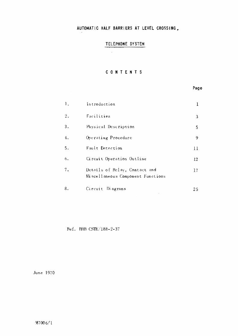
C 0 N T E N T S
Page
l. In traduction 1
2. Facilities 3
3. Physical Description 5
4. Operating Procedure 9
5. Fault De tee ti on 11
6. Circuit Operation Outline 12
7. Details of Relay, Contact and 17 Miscellaneous Component Functions
8. Circuit Diagrams 25
Ref. BRB CSTE/188-2-37
June 1970
M7006/l
I . INTRODUCTION
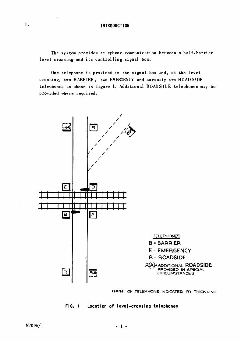
The system provides telephone communication between a half-barrier level crossing and its controlling signal box.
One telephone is provided in the signal box and, at the level
crossing, two BARRIER, two EMEfliENCY and normally two ROADSIDE
telephones as shown in figure 1. Additional ROADS IDE telephones may be provided where required.
FIG. I
~ / /
/ /
/ /
/ /
/
/ /
/
/ /
/ / //~
/<~-;. / v
/
TELEPHONES
8: BARRIER E =- EMERGENCY R=- ROADSIDE
R(A)= ADDITIONAL ROADSIDE. PROVIDED IN SPECIAL CIRCUMSTANCES
FRONT OF TELEPHONE INDICATED BY THICK LINE
Location of level-crossing telephones
M7006/l - 1 -
Two relay sets are provided to supply power to the telephones in the signal box and at the level crossing, and control the signalling between them. One is mounted in the signal box or relay room and the other near the crossing.
The system provides for alternative modes of operation depending on whether the signal box is manned full-time or part- time. The particular mode is selected by strap insertion in the· Signal box Relay Control Utit
at the time of installation.
The equipment is designed to use the existing line pair between the level crossing and the signal box, being able to work over a loop resistance of up to 2500 ohms.
Ring tone of the type used by the British Post Office 1s provided for the 1 evel-crossing telephones.
Emergency calls can be signalled at all times, overriding non•
emergency signals between the level crossing and the signal box. Discriminating signals 1n the si goal box provide immediate identification of emergency calls.
The ~in elements of the system are monitored continuously to ensure maximum reliability, and safe8Uards are provided against failure by
misoperation.
- 2 - M7006/l
2. FACILITIES
BARRIER and ROADS IDE telephones are provided with the same
facilities; EMERGENCY and SIGNALBOX telephones each have different
facilities, as detailed below. Fault-monitoring facilities are also listed.
2. I BARRIER/ROADSIDE TELEPHONES
(a) pressbutton calling
(b) bell for each of two BARRIER and two (or more) ROADSIDE telephones.
(The sound level of the bells can be varied by a common volume
control in the Barrier Control Relay Unit).
(c) interrupted ring tone immediately call is registered at the
signal box.
(d) continuity of conversation even if press button 1s kept
pressed during the call.
(e) gives buzzer and steady lamp signal at signalbox.
2.2 EMERGENCY TELEPHONES
(a) pressbutton calling.
(b) interrupted ring tone immediately call 1s registered at the
signalbox.
(c) priority signalling, even with the SIGNALBOX telephone
handset off its rest.
(d) continuity of conversation even if pressbutton 1s kept pressed
during the call.
(e) g1Ves bell (or bells) and flashing lamp signals at the signal
box.
2.3 SIGNALBOX TELEPHONE
(a) pressbutton calling
(b) continuou!'! ring tone while calling the level crosswg.
(c) emergency call signals received even if the handset is not
replaced on its rest.
(d)
(e)
ring tone, bell and lam';') signals g1Ven if an EMERGENCY
telephone calls during an established conversation.
REMOTE/ ABSENT switch
M7006/l - 3 -
REMOTE control is established over contacts of the signalbox
'block' switch to cover the circumstances where the signalbox closes
but .the railway remains open and the barrier telephones are switched
through to ~n open signalbox.
ABSENT control is established over contacts of a special
switch provided to meet the circumstances where the railway is
closed and the barrier telephones are not switched through to
another signal box.
2.~ FAULT MONITORING
The following faults automatically g1ve nse to an alarm.
(a) failure of communication power supply at level crossing.
(b) disconnection of EMERGENCY telephone cable or handset cord.
(c) disconnection, reversal or short circuit of the telephone
line between the level crossing and the signalbox.
- 4 - M7006/l
3.
M7006/l
PHYSICAL DESCRIPTION
The ma1n elements of the system are:
Level-crossing telephones
Signalbox telephone
Signalbox control relay unit
Barrier (level-crossing) control relay unit
Their physical characteristics are described below:
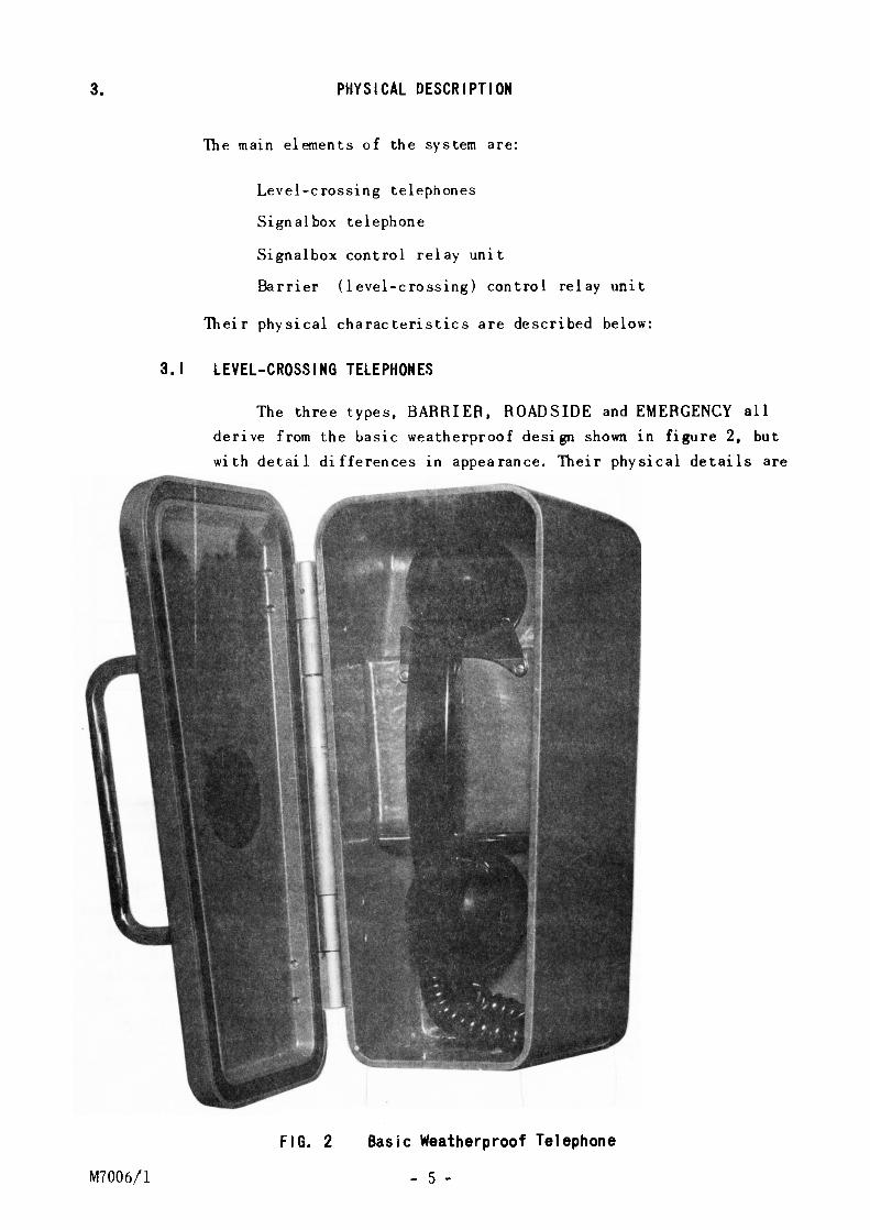
3.1 LEVEL-CROSSING TELEPHONES
The three types, BARRIER, ROADSIDE and EMERGENCY all
derive from the basic weatherproof design shown in figure 2, but
with detail differences in appearance. Their physical details are
compared in table 1.
FIG. 2 Basic Weatherproof Telephone
- 5 -
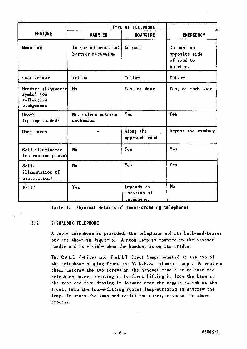
,.. TYPE OF TELEPHONE
FEATURE BARRIER ROADSIDE EMERGENCY
Mounting In (or adjacent to) <Al post On post on barrier me ch ani sm opposite side
of road to barrier.
Case Colour Yellow Yellow Yellow
Handset silhouette No Yes, on door Yes, on each side symbol (on reflective background
Door? No, unless outside Yes Yes (spring loaded) mechanism
J:hor faces - Along the Across the roadway approach road
Self-illuminated No Yes Yes instruction plate?
Self- No Yes Yes
illwnination of press button?
Bell? Yes Depends on No location of teleohone.
Table I. Physical details of level-crossing telephones
3.2 SIGNALBOX TELEPHONE
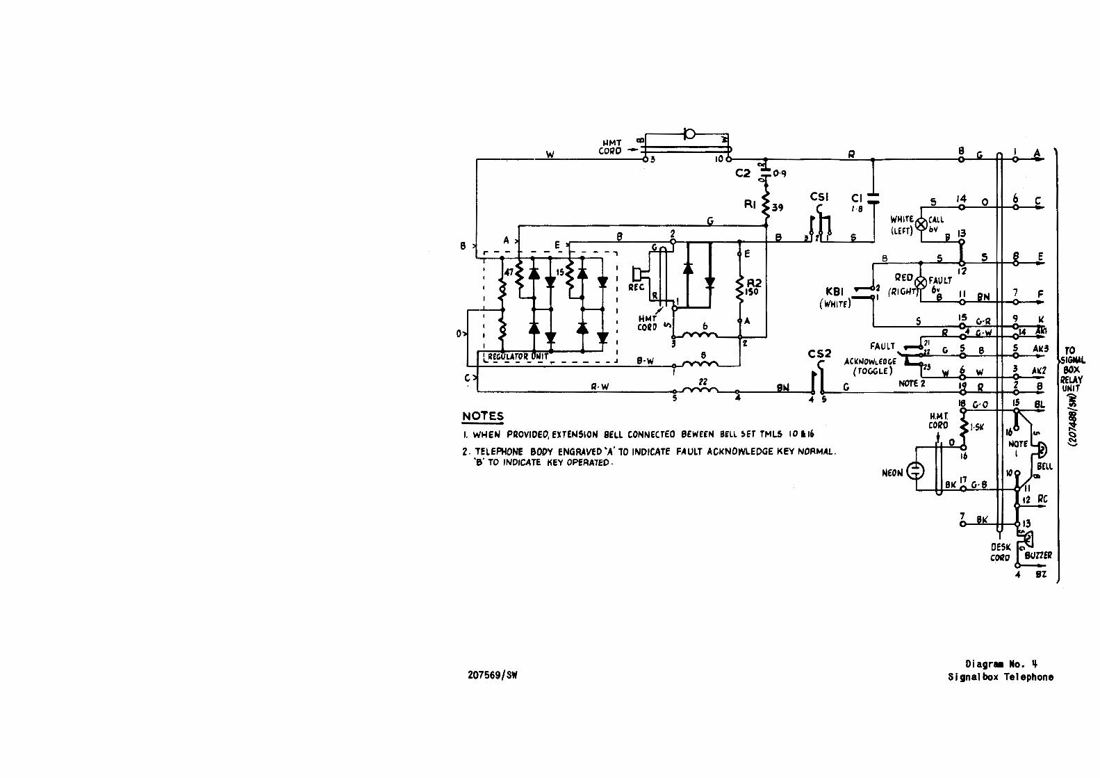
A table telephone is provided; the telephone and its bell-and-buzzer box are shown in figure 3. A neon lamp is mounted in the handset handle and is visible when the handset is on its cradle.
The CALL (white) and FAULT (red) lamps mounted at the top of the telephone sloping front are 6V M.E.S. filament lamps. To replace them, unscrew the two screws in the handset cradle to release the telephone cover, removing it by first lifting it from the base at the rear and then drawing it forward over the toggle switch at the front. Grip the loose-fitting rubber lamp-surround to unscrew the lamp. To renew the lamp and re-fit the cover, reverse the above process.
- 6 - M7006/l
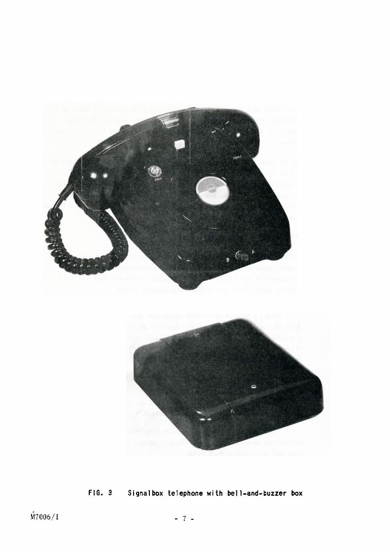
Fl G. 3 Signalbox telephone with bell-and-buzzer box
M7006/l - 7 -
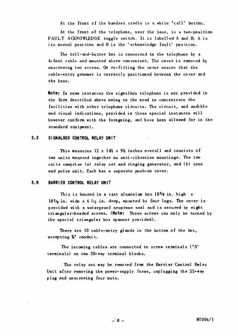
At the front of the handset cradle is a white •call' button.
At the front of the telephone, near the base, is a two-position FAULT ACKNOWLEDGE toggle switch. It is labelled A and B; A 1s its normal position and B is the 'acknowledge fault' position.
The bell-and-buzzer box is connected to the telephone by a 4-foot cable and mounted where convenient. The cover is removed by
unscrewing two screws. On re-fitting the cover ensure that the
cable-entry g~mmet is correctly positioned between the cover and
the base.
Note: In some instances the signalbox telephone is not provided in
the fonn described above owing to the need to concentrate the
facilities with other telephone circuits. The circuit, and audible
and visual indications, provided in these special instances will
however confonn with the foregoing, and have been allowed for in the
standard equipment.
3.3 SIGNALBOX CONTROL RELAY UNIT
This measures 12 x 14Yz x 9~ inches overall and consists of
two units mounted together on anti-vibration mountings. The two
units comprise (a) relay set and ringing generator, and (b) tone
and pulse unit. Each has a separate push-on cover.
3.~ BARRIER CONTROL RELAY UNIT
This is housed in a cast aluminium box 18~8 in. high x
183/a in. wide x 6 lf2 in. deep, mounted by four lugs. The cover 1s
provided with a waterproof neoprene seal and is secured by eight triangular-headed screws. (Note: These screws can only be turned by the special triangular box spanner provided).
There are 10 cable-entry glands in the bottom of the box,
accepting ~· conduit.
The incoming cables are connected to screw tenninals (•s• terminals) on two 30-way terminal blocks.
The relay set may be removed from the Barrier Control Relay
Unit after remonng the power-supply fuses, unplugging the 55-way
plug and unscrewing four nuts.
- 8 - M7006/1
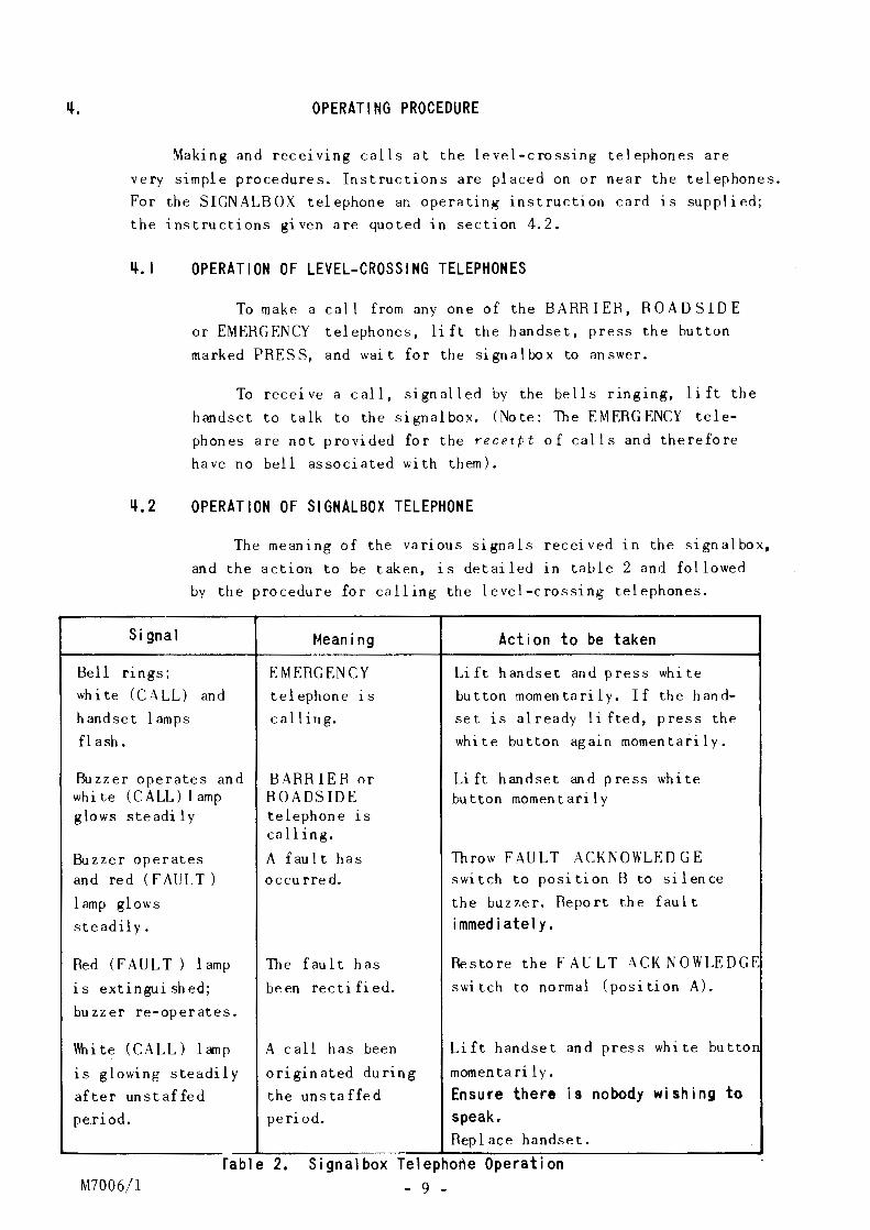
~. OPERATING PROCEDURE
Making and receiving calls at the level-crossing telephones are
very simple procedures. Instructions are placed on or near the telephones.
For the SIGN ALB OX telephone an operating instruction card is supplied;
the instructions given are quoted in section 4.2.
~.I OPERATION OF LEVEL-CROSSING TELEPHONES
To make a call from any one of the BARRIER, ROADSIDE
or EMERGENCY telephones, lift the handset, press the button
marked PRESS, and wait for the signal box to answer.
To receive a call, signalled by the bells ringing, lift the
handset to talk to the signalbox. (Note: The EMERGENCY tele
phones are not provided for the recetpt of calls and therefore
have no bell associated with them).
~.2 OPERATION OF SIGNALBOX TELEPHONE
The meaning of the various signals received in the signalbox,
and the action to be taken, is detailed in table 2 and followed
by the procedure for calling the level-crossing telephones.
Signal
Bell nngs;
wh i te (CALL) and
handset lamps
flash.
Buzzer operates and white (CALL) 1 amp glows steadily
Buzzer operates and red ( F AU L T )
1 amp glows
steadily.
Red (FAULT ) 1 amp
is extinguished;
buzzer re-operates.
\\bite (CALL) lamp
is glowing steadily
after unstaffed
period.
t~ean i ng
EMERGENCY
telephone 1s
calling.
BARRIER or ROADSIDE telephone is calling.
A fault has occurred.
The fault has
be en rectified.
A call has been
originated during
the uns ta ffe d
period.
Action to be taken
Lift handset and press white
button momentarily. If the hand
set is already lifted, press the
white button again momentarily.
Lift handset and press white button momentarily
Throw FAULT ACKN OWL EDGE switch to position B to silence
the buzzer. Report the fault
immediately.
Restore the FAULT ACKNOWLEDGE
switch to normal (position A).
Lift handset and press white but ton
momentarily.
Ensure there is nobody wishing to speak. Replace handset.
M7006/l
fable 2. S1gnalbox Telephone Operat1on - 9 -

Outgoing Call: Lift handset and press white button. The bells at the
level crossing ring while the button is depressed. The white (CALL)
lamp glows steadily while the handset is lifted.
If there is no answer, press the white button aga1n.
- 10 - M7006/l
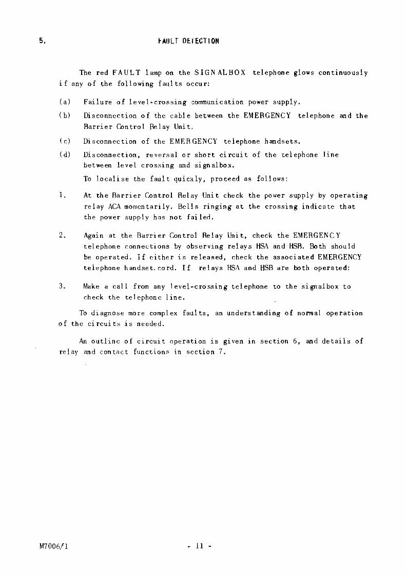
5. FAULT DETECTION
The red FAULT lamp on the SIGNALBOX telephone glows continuously
if any of the following faults occur:
(a) Failure of level-crossing communication power supply.
(b) Disconnection of the cable between the EMERGENCY telephone and the
Barrier Control Relay Unit.
(c) Disconnection of the EMERGENCY telephone handsets.
(d) Disconnection, reversal or short circuit of the telephone line
between level crossing and signalbox.
To localise the fault quic'dy, proceed as follows:
l. At the Barrier Control Relay Unit check the power supply by operating
relay ACA momentarily. Bells ringing at the crossing indicate that
the power supply has not failed.
2. Again at the Barrier Control Relay Unit, check the EMERGENCY
telephone connections by observing r.elays HSA and HSB. Both should
be operated. If either is released, check the associated EMERGENCY
telephone handset.cord. If relays HSA and HSB are both operated:
3. Make a call from any level-crossing telephone to the signalbox to
check the telephone line.
To diagnose more complex faults, an understanding of normal operation
of the circuits 1s needed.
An outline of circuit operation 1s g1ven 1n section 6, and details of
relay and con tact functions in section 7.
M7006/l - ll -
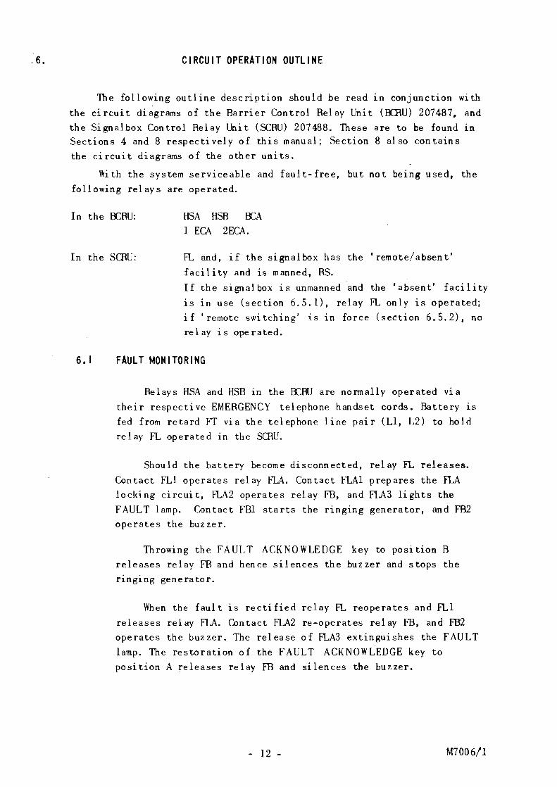
'6. CIRCUIT OPERATION OUTLINE
The following outline description should be read in conjunction with
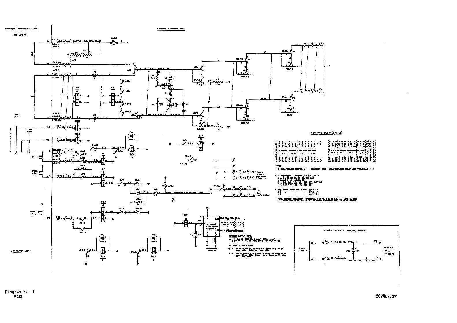
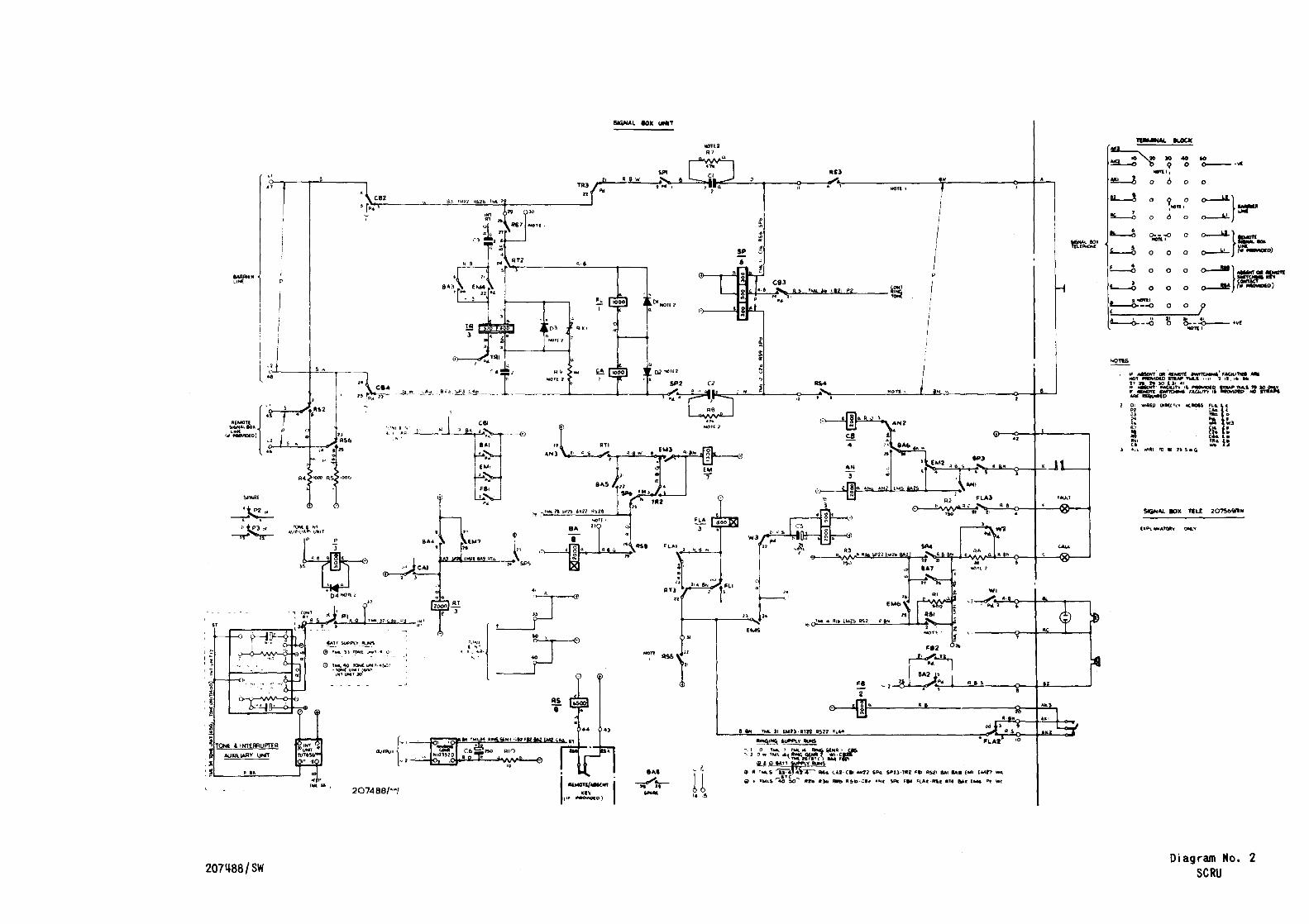
the circuit diagrams of the Barrier Control Relay Unit (ECRU) 207487, and the Signalbox Control Relay Unit (SCRU) 207488. These are to be found in Sections 4 and 8 respectively of this manual; Section 8 also contains the circuit diagrams of the other units.
With the system serviceable and fault-free, but not being used, the following relays are operated.
In the OCRU:
In the sam:
HSA HSB 1 ECA 2ECA.
FL and, if the signalbox has the 'remote/absent'
f aci 1 i ty and is man ned, RS.
If the signalbox is unmanned and the 'absent' facility
is in use (section 6.5.1), relay FL only is operated; if 'remote switching' is in force (section 6. 5. 2), no relay is operated.
6. I FAULT MONITORING
Relays HSA and HSB in the ECRU are normally operated v1a
their respective EMERGENCY telephone handset cords. Battery 1s fed from retard FT via the telephone line pair (L1, L2) to hold relay FL operated in the SCJ\U.
Should the battery become disconnected, relay FL releases.
Contact FL1 operates relay FLA. Contact FLA1 prepares the FLA locking circuit, FLA2 operates relay FB, and FLA3 lights the FAULT lamp. Contact FBl starts the ringing generator, and FB2 operates the buzzer.
Throwing the FAULT ACKNOWLEDGE key to position B releases relay FB and hence silences the buzzer and stops the ringing generator.
When the fault 1s rectified relay FL reoperates and FLl
releases relay FLA. Contact FLA2 re-operates relay FB, and FB2 operates the buzzer. The release of FLA3 extinguishes the FAULT
lamp. The restoration of the FAULT ACKNOWLEDGE key to position A releases relay FB and silences the buzzer.
- 12 - M7006/1
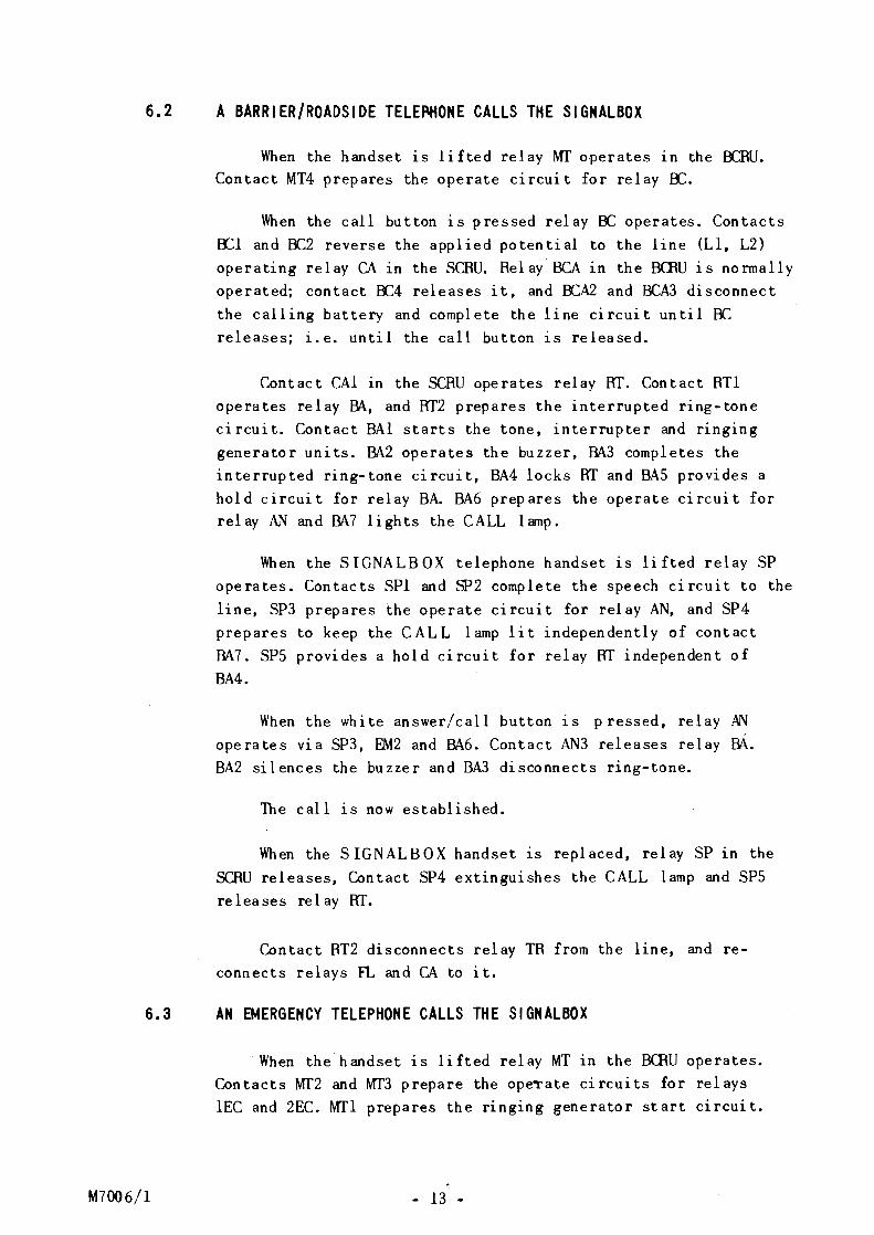
6.2 A BARRIER/ROADSIDE TELE~ONE CALLS THE SIGNALBOX
When the handset is lifted relay MT operates 1n the OCRU. Contact MT4 prepares the operate circuit for relay BC.
When the call button is pressed relay BC operates. Contacts BCl and BC2 reverse the applied potential to the line (Ll, L2) operating relay CAin the SCRU. Relay BCA in the BCRU is normally operated; contact BC4 releases it, and BCA2 and BCA3 disconnect the calling battery and complete the line circuit until 8C releases; i.e. until the call button is released.
Contact CAl in the SCRU operates relay RT. Contact RTl operates relay BA, and RT2 prepares the interrupted ring-tone circuit. Contact BAl starts the tone, interrupter and ringing generator units. BA2 operates the buzzer, BA3 completes the interrupted ring-tone circuit, BA4 locks RT and BAS provides a hold circuit for relay BA. BA6 prepares the operate circuit for relay AN and BA7 lights the CALL lamp.
When the SIGNALBOX telephone handset 1s lifted relay SP operates. Contacts SPl and SP2 complete the speech circuit to the line, SP3 prepares the operate circuit for relay AN, and SP4 prepares to keep the CALL lamp lit independently of contact BA7. SPS provides a hold circuit for relay RT independent of BA4.
When the white answer/call button is pressed, relay AN operates via SP3, EM2 and BA6. Contact AN3 releases relay BA. BA2 silences the buzzer and BA3 disconnects ring-tone.
The call 1s now established.
When the S IGNALBOX handset is replaced, relay SP in the SCRU releases, Contact SP4 extinguishes the CALL lamp and SPS releases relay RT.
Contact RT2 disconnects relay TR from the line, and reconnects relays FL and CA to it.
6.3 AN EMERGENCY TELEPHONE CALLS THE SIGNALBOX
M7006/l
When the handset is lifted relay MT in the BCRU operates. Contacts MT2 and MT3 prepare the ope~ate circuits for relays lEC and 2EC. MTl prepares the ringing generator start circuit.
- 13 -
When the call button on EMERGENCY telephone No. 1 is pressed relay lEC operates. (Note: Relay 2EC would operate if the call was from EMERGENCY telephone No. lA). lECA (and 2ECA) are normally operated. Contact lECl completes the ringing generator start circuit and 1EC3 and 1EC6 apply 25Hz a.c. to the line (Ll, L2) to operate relay CA in the SCRU.
Contact CAl operates relay RT. Contact RTl prepares the operate circuit for relay EM, and RT2 completes the circuit for relay TR, which operates to the incoming 25Hz a.c. Contact TR2 operates relay EM via RTl and AN3.
In the ECRU, contact lECS releases relay lECA, and contacts 1ECA2 and 1ECA3 disconnect the calling a.c. and complete the line circuit until lEC releases; i.e. until the call button is released.
When relay EM operates in the SCRU, contact EMl starts the tone, interrupter and ringing-generator units. Contact EM2 prepares the operate circuit for relay AN, EM3 holds relay EM, and EM4 completes the interrupted ring- tone circuit when TR releases. Contact EMS operates relay W, EM6 prepares the-CALL lamp flashing circuit and EM? holds relay RT. Relay W pulses and contact W2 flashes the CALL lanp; Wl flashes the handset neon lamp and causes interrupted ringing of the bell(s).
When the SIGNALBOX telephone handset is lifted, relay SP operates in the SCRU. Contacts SPl and SP2 complete the speech circuit to the line, SP3 prepares the operate circuit for relay AN, and SP4 prepares to keep the CALL lamp lit independently of contact EM6. Contact SPS prepares to hold relay RT.
When the white answer/call button is pressed, relay AN
operates. Contact AN3 releases relay EM.
Contact EMS releases relay W. Contact W2 stops the CALL lamp flashing (i·t now glows steadily) and Wl disconnects the neon lanp and bell(s).
The call is now established.
When the S IGNALBO X handset 1s replaced, relay SP in the SCRU releases. Contact SP4 extinguishes the CALL lamp and SP5 releases relay RT. Contact RT2 disconnects relay TR from the line and reconnects relays FL and CA to it, restoring the circuit to normal.
- 14 - M7006/l
M7006/1
6.~ THE SIGNALBOX TELEPHONE CALLS THE LEVEL CROSSING
When the SIGNALBOX telephone handset is lifted, relay
SP operates in the SCRU. Contacts SPl and SP2 complete the speech circuit to the line, SP3 prepares the operate circuit for relay CB, SP4 lights the CALL lamp and SP5 operates relay RT. Contact SP6 disconnects the operate circuit of relay BA.
When the white call/answer button is pressed, relay CB
operates. Contact CB1 starts the tone unit and ringing generator, and CB2 and CB4 extend 25 Hz a.c. to line (Ll, L2) to operate relay AC in the ECRU. Contact CB3 completes the continuous r1ng tone circuit.
Relay contact AC1 closing in the BCRU operates relay ACA. Contact ACAl starts the ringing generator and ACA3 completes the circuit to the bells.
When the white call/answer button is released and the
level crossing answers, the call is established.
6,5 'ABSENT' SWITCHING (LINE CLOSED) and 'REMOTE SIGNALBOX' SWITCHING (BLOCK CLOSED)
The circuit operation described in sections 6.1 to 6.4 applies while the signalbox is manned. Two other modes of operation are permitted, one when the signal box is unmanned
and the railway line is closed to traffic, the other when the
signalbox is unmanned and has transferred control of the railway line to a remote signalbox.
The 'remote' and •absent' modes of operation are instituted
by throwing the REMOTE/ABSENT switch in the signalbox to release the normally operated relay RS. (Note: Where the
remote/absent facility is not provided, the six 'make' contacts of relay RS are short-circuited by straps).
6. 5. I 'Absent' condition is in force (Line closed)
(Note: To allow this mode of operation, relay contact RS7
1s strapped out, but the others are not).
A BARRIER or R 0 ADS I DE telephone call to the signal box
1s ineffective because relay BA in the SCRU is disconnected at contact RS8. Notices in the ROADSIDE telephone direct the
user to the EMERGENCY telephone if no reply is received at
the ROADSIDE telephone. An EMERGENCY telephone call
causes the operation of relay CA in the SCRU as described 1n
section 6. 3. Relays Rf, TR and EM operate as before.
- 15 -
(Relay W does not operate, s1nce contact RSS is open, so the
bell and flashing neon do not operate. Also, the CALL lamp glows
steadily instead of flashing).
Interrupted ring tone is returned to the caller.
The call will remain registered, and the CALL lanp lit,
until the signalman clears it by restoring the REMOTE/ABSENT
switch to normal and pressing the white call/answer button on
re-entering the signalbox.
6.5.2 'Remote'Switching' condition is in force (Block closed)
(Note: To allow this mode of operation none of the RS relay
contacts is strapped out).
With the REMOTE/ABSENT switch thrown and hence relay RS
released, contacts RS2 and RS6 divert the level-crossing telephone
line (Ll, L2) from the BCRU in the local signalbox to an identical
one in the remote signalbox.
The SCRU and the SIGNALBOX telephone in the local signal
box are therefore completely out of service, all the functions
having been transferred to the remote signalbox, which operates
as described in section 6.1 to 6.4.
- 16 - M7006/1
DETAILS OF RELAY, CONTACT AND MISCELLANEOUS COMPONENT
FUNCTIONS
Relays in the Barrier Control Relay Unit (BCRU) and the Signalbox
Control Relay Unit (SCRU) are listed in alphabetical order, and their
cause of operation and contacts' functions are described in detail
(section 7.1). A second list (section 7.2) describes the functions of
miscellaneous components: resistors, diodes and capacitors.
The circuit diagrams of the BCRU and the SCRU are contained Sections 4 and 8 respectively.
7. I RELAY AND CONTACT FUNCTIONS
Relay AC
ACl
AC2 } AC3
Relay ACA
ACAl
ACA2
,ACA3
ACA4
Relay AN
ANl
AN2
AN3
Relay BA
M7006/l
(BCRU) is operated by 25Hz a.c. from the signalbox.
operates relay ACA after a brief delay (about 40 ms.)
prevent ringing current being extended to the level-crossing
telephones or shunted through the bridge relays FT and MT.
(OCRU) is operated by contact ACl after a brief delay (about
40 ms).
The delay prevents false operation by transient signals.
starts the local ringing generator via lead ST.
supplies d.c. to an extension bell (where fitted).
supplies 25 Hz a.c. from the local ringing generator to the
level-crossing telephone bells.
IS spare.
(SCRU) is operated by the call/answer pressbutton, provided the
handset has been lifted, via contact SP3 and either EM2 if an
emergency call or BA6 if a non-emergency call.
holds relay AN via contact SP3 and the pressbutton, independently
of EM2 and BA6.
prevents relay CB operating.
releases relay EM or BA, whichever Is operated.
(SCRU) is operated (after a delay of abbut 50 ms) via
contacts AN3, RTl, EM3, TR2, SP6 and RS8 (or strap) on
receipt of a non-emergency call. The delay prevents relay BA
operating on receipt of an emergency call.
- 17 -
BAl starts the tone and interrupter auxiliary unit, and the r1ng1ng
generator.
BA2 connects the buzzer to the 25Hz a.c. supply.
BA3 connects interrupted ring tone to the 'primary' winding of
relay TR.
BA4 holds re 1 ay R T.
BAS holds relay BA via contacts AN3, RTl and RS8 (or strap).
BA6 selects relay AN instead of CB for operation by the call/answer
pressbutton.
BA7 lights theCA LL lamp Vla contact W2.
BA8
Relay BC
OCl~
OC2~
OC3
1 s spare.
(ECRU) is operated by the call button of any BARRIER or
ROADSIDE telephone if contact MT4 is closed, i.e. if a
handset has been lifted.
reverse the potential applied to the telephone line (Ll, L2) to call the signalbox.
holds relay OC operated after the handset is replaced, should
the call button fail to release. This ensures that subsequent
lifting of an EMERGENCY telephone handset does not simulate
a BARRIER or ROADSIDE telephone call.
BC4 allows relay BCA to release after not less than 200 ms (delay
imposed by diode 04). Holds relay BC until contact OCAl opens,
to ensure a calling signal of not less than 200 ms duration to
operate the call circuit in the signalbox.
Relay BCA (ECRU) is normally operated. Released by contact OC4, after a
delay of not less than 200 ms. This delay determines the
duration of the reversed -battery calling signal fed via the
line to the SCRU.
BCAl
BCA2 z OCA3 ~
Relay CA
CAl
holds relay BC until relay BCA releases. See contact BC4.
on release, disconnect the calling (reversed potential)
battery used on a non-emergency call, and maintain the line
connection until relay BC releases.
(SCRU) is operated by reversed-battery or 25Hz a.c. calling
signals from the ECRU.
operates relay RT.
- 18 - M7006/l
Re 1 ay CB
CBl
CB2
CB4
CB3
}
Relay EM
EMl
EM2
EM3
EM4
EMS
EM6
EM7
Relay FB
FBl
FB2
Relay FL
FLl
Re 1 ay FLA
M7006/l
(SCR.J) is operated by the white call/answer pressbutton if
the handset is lifted (contact SP3 closed) via contacts EM2,
BA6 and AN2 nonnal to call the level crossing.
starts the tone and interrupter auxiliary unit, and the
ringing generator.
extend 25Hz a.c. to line (Ll, L2) to rmg the bells at the
level crossing.
connects continuous nng tone to the S IG NALBO X telephone,
by transformer action in relay SP.
(SCRU) is operated via contacts AN3, RTl, EM3 and TR2 on
receipt of a calling signal from an EMERGENCY telephone.
starts the tone and interrupter auxiliary unit and the
r1ng1ng generator.
selects relay AN instead of CB for operation by the call/answer
pres sbu t ton.
holds relay EM v1a RTl and AN3, and disconnects relay BA.
connects interrupted ring tone to the 'primary' winding of
relay m. starts relay W pulsing
prepares theCA LL lamp flashing circuit.
holds relay RT.
(SCRU) is operated by contact FLA2 (operated) v1a the normal
contacts of the FAULT ACKNOWLEDGE key, or vice versa.
starts the ringing generator and the tone and interrupter
auxiliary unit.
connects the buzzer to the 25 Hz a.c. supply.
(SCRU) is normally operated. Released by reversal or
disconnection of battery from the BCRU, to detect faults.
on release, operates relay FLA after about 50 ms via RSS
(or strap) and RT3.
(SCRU) is operated after about 50 ms by the release of relay
FL. (See FLl). The delay covers the re-operate time of relay
FL on cl ea rdown.
- 19 -
FLAl holds relay FLA Vla contacts RT3 and RSS (or strap).
FLA2 operates relay FB. (See above).
FLA3 lights the FAULT lamp.
Relay FT (BCRU) 1s a battery-feeding retard and has no contacts.
Relay HSA (BCRU) 1s normally operated. Released if a discontinuity occurs
in the handset cord or the cable of EMERGENCY telephone No. 1.
HSAl } HSA2
disconnect the positive and negative potentials on lines Ll and
L2 to operate the fault circuit in the SCRU.
Relay HSB (OCRU) has the same function as HSA but for EMERGENCY telephone
No. lA.
Relay MT (BCRU) is operated when the handset of any of the level cross1ng
telephones is lifted. Provides microphone current for the level
crossing telephones.
MTl
MT2} MT3
MT4
Relay P
Pl
prepares the ringing generator start circuit.
if the call is from an EMERGENCY telephone, operate relay lEC
or 2EC when the call button is pressed.
if the call Is from a ROADSIDE or BARRIER telephone,
operates relay BC when the call button is pressed.
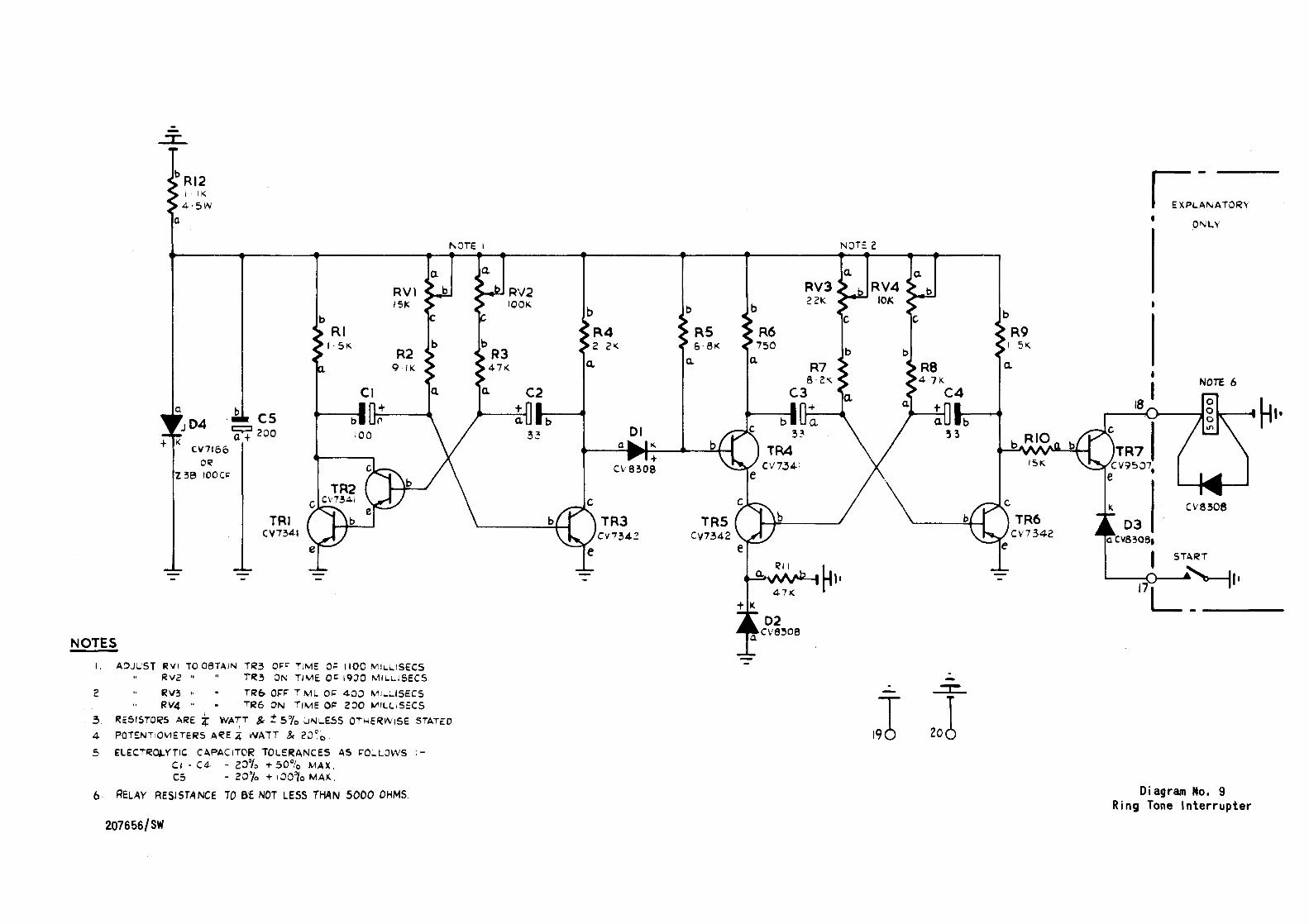
(SCRU) is pulsed at the interrupted ring tone cadence (400/200/
400/2000 ms) by the ring tone interrupter circuit.
connects continuous nng tone from the tone unit, breaking it
into the cadence shown above, to the 'primary' wtinding of relay
TR which acts as a tone transformer.
P2-P4 are spare.
Relay RS (SCRU) is normally operated if a REMOTE/ABSENT switch is provided.
Released by throwing the REMOTE/ABSENT switch into the
'signalbox unmanned' position.
(Note: Where no REMOTE/ABSENT switch 1s provided,
all the AS-relay contacts except those marked * are short
circuited by straps on the terminal block).
RSl on release, allows the CALL 1 amp to operate only at reduced
brilliance by removing the short circuit from across the
500-ohm resistor Rl.
RS2
RS6
normally provide fault-monitoring potentials Vla resistors R4
and RS to hold relay FL in the SCRU oi the remote signalbox.
When released, extend the level-crossing telephone line through
to the remote signal box.
- 20 - M7006/ 1
R'33 z RS4 )
RSS
RS7
RS8
Relay RT
Relay RT
RTl
Rf2
RT3
Relay SP
SPl ~
SP2 ~
SP3
SP4
SPS
SP6
Relay TR
TRl
M7006/l
on release, disconnect the SIGNALBOX telephone A and 8 lines.
on release, disconnects positive battery to relays FLA, W and FB.
on release, disconnects the incoming-signal detection circuits from the line.
on release, disconnects the operate circuit for relay BA.
(BCRU) is a retard acting as a choke in the negative battery
lead to the ringing generator. It has no contacts.
(SCRU) 1s operated initially, on an incoming call by contact CAl,
or, on lifting the SIGNALBOX telephone handset, by contact
SPS.
operates relay EM on receipt of a call from an EMERGENCY
telephone, or relay BA if a ROADSIDE or BARRIER telephone
calls.
transfers the level-crossing Ll line connection from relays FL and CA to relay TR to prep are for the receipt of EM ERG EN CY
telephone ringing current from the line, or the connection of
interrupted ring tone to it.
disconnects the operate circuit of relay FLA, but holds FLA Vl a
contact FLAl if it 1s already operated.
(SCRU) is operated by the SIGNALBOX telephone-line loop when
the handset is lifted. It provides microphone current to the
SIGNAL SO X telephone.
extend the speech circuit to the level - crossing line.
prepares the operate circuit of the "call' and 'answer' relays
CB and AN for operation by the white call/answer button on the
SIGNALBOX telephone.
lights the CALL lamp.
operates (or holds) relay RT.
breaks the operate circuit of relay BA.
(SCRU) is operated by the burst of ringing current which is
received from the BCIU when an EMERGENCY telephone call button
is pressed.
disconnects interrupted r1ng tone while ringing current 1s being
received from the OCRU.
- 21 -
TR2
1R3
Relay W
Wl
W2 W3
Relay I EC
lECl
1EC2
1EC3 ~
1EC6 )
1EC4
lECS
Relay IECA
lECAl
1ECA2 ~
1ECA3 )
Relay 2EC
Relay 2ECA
disconnects the operate circuit of relay BA and operates
'emergency' relay EM.
disconnects line Ll from A to prevent ringing current from
passing to the SIGNALBOX telephone, should its handset be
lifted.
(SCRU) is self-interacting at about 3 p.p.s. when connected to
the battery supply via contacts EMS and RSS (or strap).
intermittently connects ringing current to the S IGNALBO X
telephone bell and the handset neon lamp.
flashes the CALL lamp on the SIGNA LBO X telephone.
together with relay W and capacitor CS, constitutes the self
interacting circuit.
(BCRU) is operated vi a contact Mf2 when the CALL button of
EMERGENCY telephone No. 1 1s pressed.
starts the ringing generator by connecting positive battery v1 a
contact lECAl (normally closed) and Mfl.
holds relay lEC operated after the handset 1s replaced, should
the call button fail to release. This ensures that subsequent
lifting of a BARRIER or ROADSIDE telephone handset does
not simulate an EMERGENCY telephone call.
connect ringing current via contacts 1ECA2 and 1ECA3, and the
line (Ll, L2) to the SCRU.
holds relay lEC until contact lECAl opens, to ensure a calling
signal of not less than 200 ms duration to operate the call
circuit in the signa lbox.
allows relay lECA to release after not less than 200 ms (delay imposed by diode DS).
(ECRU) is normally operated. Released by contact lECS after a
delay of not less than 200 ms. This delay determines the
duration of the burst of ringing current fed vi a the line to the
S::RU.
holds relay lEC until relay lECA releases. (See contact 1EC4).
On release, contact lECAl stops the ringing generator.
on release, disconnect the ringing-current call signal and
maintain the line connection until relay lEC releases.
(BCRU) is similar to relay lEC but for EMERGENCY telephone
No. lA.
(ECRU) is similar to relay lECA but for EMERGENCY telephone
No. lA.
- 22 - M7006/l
7.2 MISCELLANEOUS COMPONENT FUNCTIONS
M7006/l
Capacitors in BCRU:
Cl, C2, C3
C4
C5
provide d.c. blocking.
with retard RT, decouples the ringing generator
battery supply.
smoo thes the power supply.
Capacitors in SCRU:
Cl, C2, C4
C3
C5
C6
Diodes in BCRU:
01, 02
D3
04
05, 06
Diodes in SCRU:
01, 02
D3
04
provide d.c. blocking.
at tenuc:~tes induced t ransi en t ringing current.
determines the pulsing frequency of relay W.
with resistor RlO, decouples the ringing
generator power supply.
rectify the 25Hz a.c. to operate relay AC.
with R4, provides a discharge circuit for
capacitor C3.
imposes 200 ms (minimum) release delay on relay
BO\.
Impose 200 ms (minimum) release delay on relays
lECA and 2ECA.
allow relay FL orCA to operate to d.c. depending
on its direction, and CA to operate to 25Hz a.c.
rectifies the 25 Hz a. c. to operate relay TR.
safeguards the output transistor 1n the Ring
Tone Interrupter circuit against back e.m. f.
Resistors in BCRU:
Rl
R2,R3
R4
R5A/B/C
R6
RVl
sets lower limit of nnging voltage (if volume
control is connected).
limit d.c. to protect the battery against line
short circuit.
via 03, discharges capacitor C3.
form part of the ringing generator circuit.
drops voltage applied to the ringing generator.
variable resistor. If connected, it controls the
25Hz ringing voltage applied to the level
crossing telephone bells.
- 23 -
Resistors in SCRU:
Rl
R2, R3
R4, RS
R6
R7, R8
R9
RlO
RXl
reduces the current through the CALL lamp under 'absent'
conditions.
drop battery voltage from SOV to 6V to operate FAULT and
CALL lamps.
limit the current fed to the S::RU in the remote signalbox,
protecting the battery against line short circuits.
maintains a low current through the CALL 1 amp during the
'off' phase of flashing to prolong lamp life.
provide 'wetting' current for relay contacts.
discharges capacitor C4.
with capacitor C6, decouples the ringing generator power
supply.
IS a non-linear resistor which prevents spurious operation
of relay TR by transient telephone-line signals.
- 24 - M7006/l
8.
M7006/1
CIRCUIT DIAGRAMS
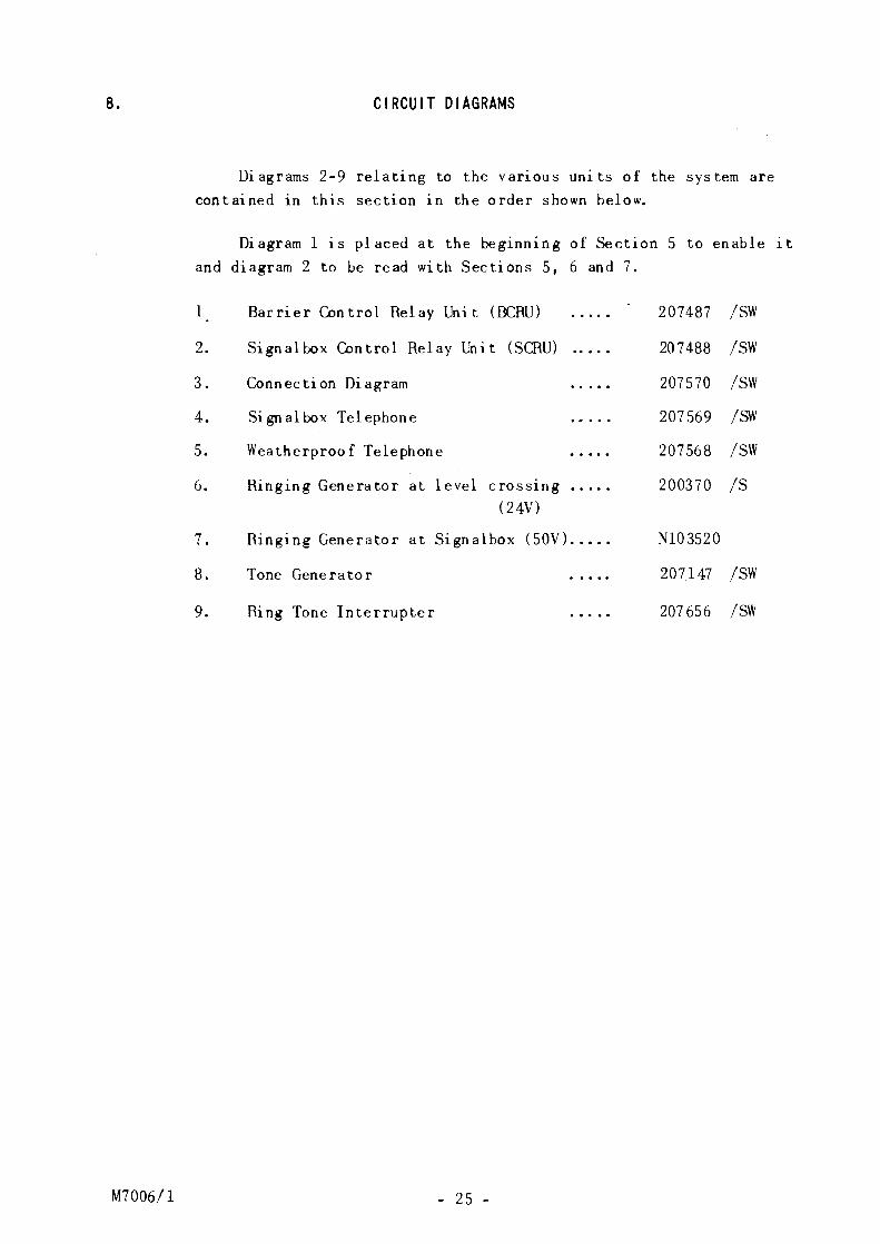
Diagrams 2-9 relating to the var1ous units of the system are contained in this section in the order shown below.
Diagram 1 is placed at the beginning of Section 5 to enable it and diagram 2 to be read with Sections 5, 6 and 7.
1
2.
3.
4.
5.
6.
7.
8.
9.
Barrier Control Relay Unit (BCRU)
Signalbox Control Relay Unit (SCRU)
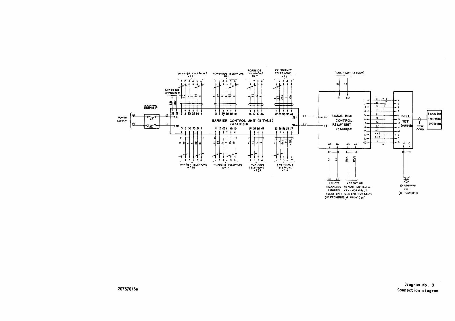
Connection Diagram
Signalbox Telephone
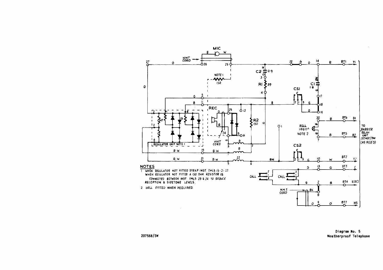
Weatherproof Telephone
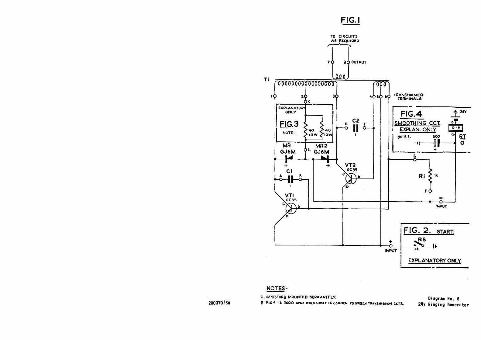
Ringing Genera tor at 1 evel c ross1ng (24V)
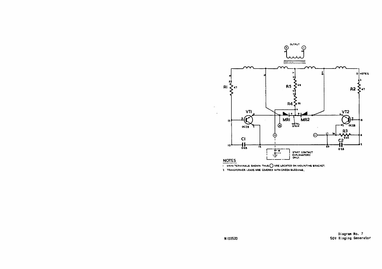
Ringing Generator at Signalbox (SOY) .....
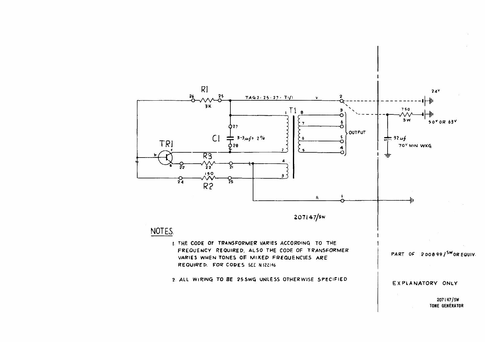
Tone Generator
Ring Tone Interrupter
- 25 -
207487 /SW
207488 /SW
207570 /SW
207569 /SW
207568 /SW
200370 /S
NlO 3520
207147 /SW
207 656 /SW
(20756IIIN)
.... , CORe-
HNT
"""" I
I
-'-"'U. lA
l EXPLAN~TORY)
Diagram No, BCRU
p p
IICI
-I
AG2
p
IICAI
.~~~~~~·u~
06
+ NOTU
..
~R CONTROL uon
06 4
+ .......
ZICA T
·A
•
ICI
0
• ,..
~
""' "''
,-1, I 8-Q
·m· ·~.__ a.., ..
IP~AI
R2
110
p
e
,_
IT
I t -0\IT..,
fN
uca • ,.. .
.,.I
tiCAl p
p
"'
~
~
"'"""' -y -
...
p p p
u .L 1..2 .. ,..
:~ 12 3 "'' • 7~1 9 10lu rt 1.JI14r-'
,o lo o o lo o o 1o o o 10 o o •o o •1 1n "•I~" tl•"" ao1n11 "' I I I I I 1. IIIM"tlf'l el-f~ IMMIIP'Ii..,._l 1"•1 ND t I ,._ lA I ,.. I I ... "'1 I 1 I I 1 1e 'i C H I t etl i t It II C It I :o 1o o ojo o 010 o o 1o o 010 o , .. ,. • .w,• M ,.,» Jilt ..a,., • .u, ... e
, t .. lVir . '11:fl.1n'"Hi'" -fo.wHt . . ~Hi.-Ht ·~---~·.:. m · : Ui al:rrr
I 04 -D _, .... , ,.._. ac .. \& n · · ·· lltA• •
- IleA• • I - ACa. •
wol
POWER SUPPLY ARRNICilMENTS I I
::' ~ ~ ... '.\t;"t:~-"'tf.·o~A'Ii"~u"
{
e ~ R l!o!LJI! "-·'ll Sl~ .]TERMINAl. ! 1 ... I cs &LOCI<
(5 T .. L5)
___,..!_A,., ! .., :~ • I y 1 :,o 9 9 ~-- M :.0 c .. -u•I•• , ...
207~87/SW
. ~ It: ' ~ '?
':il
e.AAAIE-A
'""
••
~ TC!!l & IN1ti¥'UI'I£R
AUlULIAAY UNIT ,,; '~ ' ..
2071l-88/SW
' p
R4
e.-.n_ ~PlY __ ~
® '~ )) l'Ott( _....,. \)
0 lML4C fONt ~~'•4!>01 • 1~( uNIT (40C' 1Nll,Nf~
207488/'~/
TR3
"
• &
,,
'------'~-~·~-(i)
;·'~! l ' .... ;J. ·- """' '.
l
.. , -0)
•tw
,, R$5111
. ... __.,.....__ .... .....
'""" R7
ll ,.
RU
·,
Fll
NOll' ••
I I
f i
IP3
1
~~-
r I
••
• •
FLA) R2
~~.~.~·~·-c~~~---(~---1
~·2 ..
-.E.~~; ~·~· '----r-+--'----'
- ILOCIC
~ ... ... 10 q 0 e>--·" ..... ,,
~ 0 h 0 0
~ 0 ~NITIIO :-:}~ L-b 0 0 0
~ o---c 0 ~}='-..... , ~ 0 0 0 o---!aL r.:'..awxo)
~ 0 0 0 o---.!11}- 011 :h"'"" ~ 0 0 0 ~~D) ~ .... --o 0 0 f' • A I II •• .. ., ~--o 0 <>--<>--- +V(
"'""'
~
IF ~ eM 'lill..:nt IWJ~1 FAC&Jl. Alllll
NOT ~.,.. ... "nrrooi.S •·•• 'J rt,••·• !"' ~-l£/J"-41
•\ PMIYUO &'tMP ......_., 29 lO ~'t' " .,.,... ~· ~AICh./T"' '' ~p, NO 1-ntAPI AA( ..,..lO
SIGNAL IIOl< TIL£ 2075b9/IW
Diagram No. 2 SCRU
ROADSIDE BARRIER TELEPHONE ROADSIDE TEUPHOI'IE TELEPHONE
N9 I N91 N9 2
123456 I 2 3 4 s 6 I 2 3 4
~p~ r.-- ~r ~ :.- t I_.. p _..P , ... p .... p
~XTN p.c 1111. I (1, PIIO\IIDID ~c.. ~ iii -"' u w II: iii ,::~ u .... .,_uu. ... ,_
POWFR { SUPPLY
~! === ""~3~32344 Eil (i) 19,314010 lb 17 47 46 - 31 ~2A
BARRIER CONTROL UNIT (S T'Ml.S.) 0 "r 2ii. n.._ e 207487/SW
30 563635377 II 12 42 41 43 13 19 70 50 49
>= ::: ;:: ~ 1,0 - N N- iii u ... II>ID u .. ,_,_ u w
I pjr p~~ p~ pi-_..P f't ~ ..... l .... ....
~ 123456 I 2 3 4 '--..,.-'
BARRIER TELEPHONE ROADSIDE TELEPHONE ROADSIDE N9 lA N9 lA TELEPiiONE
N9 2A
207570/SW
EMERGENCY TELEPHONE
N91
I 2 3 4 7
t _....
~ ;:: w
"
t2Z3!S-'ll4 28-
58 zs 26 5b 55 17
-"' "' II> ~ ... ...... <r>
i "
..... p~ 1 I 2 3 4 7
EMERGENCY TELEPHONE
N91A
__!,_I
L2
47
48
45
POWER SUPPLY(50V) ~
® 8
41 50 I 2 3 4
SIGNAL BCX 5
CONTROL • RELAV l.NT 7
8 20748Sf5W
9 I
X!
~ 43 ~4 42
c ' cp • Ill
:::; "' "' "' ..1
"" ""
~ '------.r-----' REMOTE ABSENT OR
SIGNAL80t REMOTE SWITCHING CONTROL KEY (NORMALLY
RELAY UNIT CLOSED CONTACT) (If PROVIDED) (IF PROVIDED}
A i 8 p
K
F --c Bl ··-
RC
B AKI
AK2 AK3 --
E -
I 2
9 -7
6 BELL -IS SET
I] 4 20756-
14 3
-5 -s 10 16
c~p
"' EXTENSION
BELL
(\
y DESK CORD
(IF PROVIDED)
SIGNALBOJ
TflEPitONt
2075o9•
Diagram No. 3 Connection diagram
e
0 b
I I
C2
e
R2 150
2
KBI (WHITE')
B
t:'AULT
8
5 14 0 6 c
13
E
F
5 15
L'~tGU_!A!_OR_ ~T.,. _ - - - - ~ S·W 6 CS2 ACICNOWLfD C.f"'r....OI.!.--=--o__,.!::__++--o-~.;.;.:
G
5
NOTES
I. WHEN PROVIDED, EXTENSION SELL CONNECTED BEWEEN SELL ~H TMLS 10 l16
2. TELEPHONE 800Y ENGRAVED 'A' 10 INDICATE FAULT ACKNOWLEDGE KEY NORMAl. '8' TO INDICATE KEY OPERATED.
207569/SW
c; (TOUGLE)
NEON
J.U.H COilO
t 0
4 BZ
Diagr• No. IJ Signalbox Telephone
TO SIGNAL sox
llELAY UNIT
t J 2 '-'
0
MIC r--=-8--lp.- w
HMT i ~ 27 COQO-o----------~0~--------- 2b ~ ~-------
G 5
"40TE I I
r--~ ISO
I
Z2
09
Rl 3' 4
lb 0
CSI Cl 1·8
14 Tl
8 e II 2 I 3 r-~~~~------~----~--~----4-~------~ 18
I
14
! - -, I
I
I
I
REC I U 2& I
I
R
I..-- ;~4 Ht.'IT
CORO _ . .J ~
I~ B·W
21 R-w ~
NOTES WHEN REC.lJLATOQ I'IOT FITTf"O 5TilAP INST TMLS 15·21· Z7. WHE!I.I REC.ULATOR NOT FITTED A ISO OHM RESISTOQ IS
CON~ECTfD BETWEEN INST TML5 23 I. 24 TO QEOUCf RECEPTION 1k SIOETOtolf LEVElS.
2 bELL. FillED WHEN REQUIRED
207568/SW
12
R2 150
s 6
8
22
CALL
1,)
llELL. IOOOA
NOTE Z
BT'Z 0
10 w o ..... --__:.:'------< 6T3 0
5 13 G
----------~r------~0~--~'-----~ CALL r=:~
.. .5
l a 2
H.M. T ----;::::~:A-!!.!8K~I~ CORD S
0 i
8T4 ---8
0
T.? • c ...
E(EC)
HS
TO 9Ailll1EI\' RELAY U.,IT
Z07487/SW (AS AEQ'D)
Diagram No. 5 Weatherproof Telephone
200370/SW
Tl
rEXPLANATO
ONLY
I FIG.3
FIG. I
TO CIRCUITS A~ RE(lUI REO ~
I NOTE '_
MRI ~==~ GJ6M
+ Cl
NOTES:·
+
I. RESISTORS MOUNTED SEPARATELY.
TRANSFORMER TE~MINALS
-G.4
OTHING CCT. EXPLAN. ONLY.
Rl IK
F
-INPUT
I FIG. 2. START.
+ ~s . .. ~ ·-o-----11·
INPUT pt.
EXPLANATORY ONLY.
Diagram No. 6 Z FIG 4 16 RE.CfO ONLY WMl!15llPPLY IS (O..,htOf TO !o9EEC.H TRlNSMtS~IOtf C.C.TS. 2~V Ringing Generator
0 > 0 NO'TC I. 8
Rl
, ~ 4
C2 H."
10._--~~-----.·~------~.------------------------._----~ 045 ~-~---,
~ \0
I _9: I
NOTES L~::__ _ _J
STl.RT 'ON'TAt.'T EXPI.ANAlORV ONI..V
I. Ml.IN TtRMINA.I..' SI-IOWN '1'1-!U&Q .. Rli..OC.A.'TtO ON MOUN'TINQ IR.A.CKC'T.
'Z TR-.NSF'ORMtR I.EAOS •Rl CO\ItRtO Wl'l'l-l CRttN il..tl~ING,
N 103520
0·1.5
Diagram No. 7 50V Ringing Generator
RJ
3K I T1 8
.-------------~ ,_---,....
"""
TRJ Cl
2
7 6 )-
'()
>- > () l
> "V
>- s 4 .{) -
OUTPUT = ~?u.J I 70v MIN w~c:;.
4
3
.__ ________ R ___ -o-----+-------tlt
207147/SW
NOTES. 1. THE CODE Of TRANSFORMER' VAR'IES ACCORDIN~ TO THE
FREQUENCY REQUIRED. ALSO THE CODE OF TI?ANSFO~ME~
VAJliES W~EN TONES 01= MIXED FREQUENCIES ARE REOUJI?E't>. FOe? CODES 5EE N 12l146
'l. ALL WIRING TO BE ?SSW4 UNLESS OTHE~WISE SPECIFIED
PART Of: ~008 99/SWOR EQUJV.
EXPLANATORY ONLY
2071 ~~/SW TONE GENERATOR
NOTES
a
a
I· IK
4·5W
JD4 + K
CV7166
0~
'Z 38 rooo=
b cs 'a•t' 200
TRI CV7341
b
RVI 151<
Rl I· 5K
R2 9 IK
I. A:>JL.:ST RVI TO OBTAIN TR.3 0~" TiME 01= 1100 MI1..LISECS RV2 " TR3 ON TIME Q>= 19JO MII.LISECS.
2 IN3 •· TRo Ql=l= T ML 01= 40,:1 MI.LISECS RV4 " TR6 ON TIME OJ:' 200 t.llllliSECS
"'OTE I
a.
. 3. li:E5JSTORS A~E i WATT & :t 5% U"JLESS OTf-<ERWISE STATED I
4 POTENTIOMETERS A~E 4 WATT & 20~ 0 .
5 ELECTR~YTIC CAPACITOR TOLERANCES AS I='OLLOWS -Cl - C4 • 20"/:> "I" SO% MAX. C5 • 201o + I 00'/o MAX.
6 RELAY RESISTANCE TO BE NOT LESS THAN 5000 OHMS.
207656/SW
b
b
b
F\4 2 2'<
a.
Dl a K
+ CVS308
TR3 CV7342
b
a.
b
RS R6 &·8K 750
a.
b
b
t K
02 a CV8306
NOT:. 2
a. 0.
b
R9 I 51<
a.
. -
• .OI\ILY
NOTE 6
03 a Cll8308t
I ST~RT
'------<.17 ~I• L ___ _
Diagram No. 9 Ring Tone Interrupter