Embed Size (px)
Citation preview
November 1986
/
AX0PR0BE-1A MICROELECTRODE AMPLIFIER
OPERATOR'S MANUAL
Written for Axon Instruments, Inc. by Alan Finkel, Ph.D.
Copyright 1986 Axon Instruments, Inc. No part of this manual may be reproduced, stored in a retrieval system, or transmitted, in any form or by any means, electronic, mechanical, photocopying, microfilming, recording, or othenwise, without written permission from Axon Instruments, Tnc.
QUESTIONS? Call (415) 340-9988
COPYRIGHT
THE CIRCUITS AND INFORMATION IN THIS MANUAL ARE COPYRIGHTED AND MUST
NOT BE REPRODUCED IN ANY FORM WHATSOEVER WITHOUT WRITTEN PERMISSION
FROM AXON INSTRUMENTS. INC.
VERIFICATION
THIS INSTRUMENT IS EXTENSIVELY TESTED AND THOROUGHLY CALIBRATED
BEFORE LEAVING THE FACTORY. NEVERTHELESS. RESEARCHERS SHOULD
INDEPENDENTLY VERIFY THE BASIC ACCURACY OF THE CONTROLS USING
RESISTOR/CAPACITOR MODELS OF THEIR ELECTRODES AND CELL MEMBRANES.
DISCLAIMER
THIS EQUIPMENT IS NOT INTENDED TO BE USED AND SHOULD NOT BE USED IN
HUMAN EXPERIMENTATION OR APPLIED TO HUMANS IN ANY WAY.

iv
V
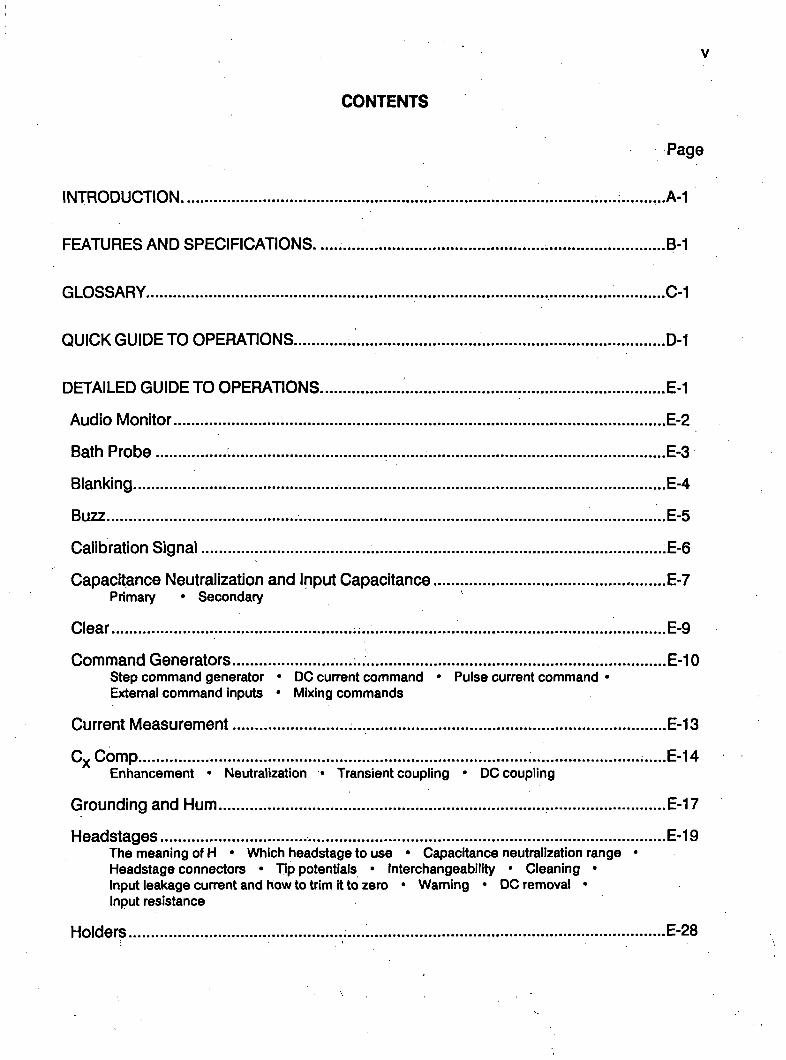
CONTENTS
Page
INTRODUCTION .....;..........A-1
FEATURES AND SPECIFICATIONS ...B-1
GLOSSARY C-1
QUICK GUIDE TO OPERATIONS D-1
DETAILED GUIDE TO OPERATIONS E-1
Audio Monitor E-2
Bath Probe : E-3
Blanking E-4
Buzz E-5
Calibration Signal .E-6
Capacitance Neutralization and Input Capacitance E-7 Primary • Secondary
Clear E-9
Command Generators E-10 Step command generator • DC current command * Pulse current command • Extemal command inputs * Mixing commands
Current Measurement E-13
C^Comp E-14 Enhancement * Neutralization • Transient coupling • DC coupling
Grounding and Hum E-17
Headstages E-19 The meaning of H • Which headstage to use • Capacitance neutralization range • Headstage connectors * Tip potentials • Interchangeability • Cleaning * Input leakage current and how to trim it to zero • Warning • DC removal * Input resistance
Holders E-28
Vll
Page
in Use/Standby E-31
lonophoresis E-32
Ion Sensitive Electrodes - Special Considerations E-33 Buzz * Capacitance neutralization
Microelectordes For Fast Settling E-34 Microelectrode capacitance • Microelectrode resistance * Filling solutions * Recommended reading
Models.. E-36
Offset E-37
Output Filters , E-38
Order • Type • Risetime
Output Impedance and Protection E-40
Panel Meters E-41
Voltage • Current • Round-off error and zero error
Power Supply Glitches E-42
Power Supply Voltage Selection and Fuse Changing E-43 Supply voltage • Changing the fuse
Resistance Compensation E-45
Description • Suggested use * Intracellular balancing
Ten-Turn Potentiometers E-48
Test Current ....E-49
Cell resistance
Troubleshooting E-50
References E-51
GENERAL INFORMATION F-1
Warranty F-1
RMA form F-3
Policy statement F-5
Service F-5
Comment form • F-7

Vlll
A-1
INTRODUCTION
The AX0PR0BE-1A multipurpose microelectrode amplifier contains two microelectrode amplifiers (ME1 and ME2). These amplifiers may be independently used for Intracellular and extracellular voltage recording with simultaneous current passing, or differentially for recording with ion-sensitive electrodes. Many built-in features make the AX0PR0BE-1A extremely convenient to use.
To learn how to make the most of these features, we advise first-time users of the AX0PR0BE-1A to read this manual thoroughly and to familiarize themselves with the instrument using resistor/capacitor models of their electrodes and cells.
We will be pleased to answer any questions regarding the theory and use of the AX0PR0BE-1A. Any comments and suggestions on the use and design of the AXOPROBE-1A will be much appreciated.
We would be most grateful for reprints of papers describing work performed with the AXOPROBE-1 A. Keeping abreast of research performed helps us to design our instruments to be of maximum usefulness to you who use them.
Axon Instruments, Inc.
^
Axon Instruments. Inc
AXOPROBE-1 A Multipurpose Microelectrode Amplif ier
ff' CURRENT DISPLAY UtCROELECTROOE I (ME1
STEP COMMAND
t ^
9
MICROELECTRODE 2 |ME7| AUOK) UONITOn
0 7 0 . « .
f » > ^
• • ; : , *
^•' 0 Fl INPUT ri lNPUT
® ifel ^^i ' 1 no FREO |H/) -3 ita FR£0 |Hf)
^ H \ ^ 4 < o f T I m t t u n i e n i i ^ m ^ ^ ^ * ^ ^ ^ •.**>• v i y ^ w i ^ ^ ^ * ^ ^ m u
AXOPROBE 1A M U L U P U R P O S E U I C R D CLICTHOOF AMPtt f l fn
i • • : . *
DUAL INTRACELLULAR AMPLIFrER plus
ION-SENSITIVE ELECTRODE AMPLIFIER plus
EXTRACELLULAR AMPLIFIER plus
lONOPHORESIS & CURRENT PASSING
m? d Q
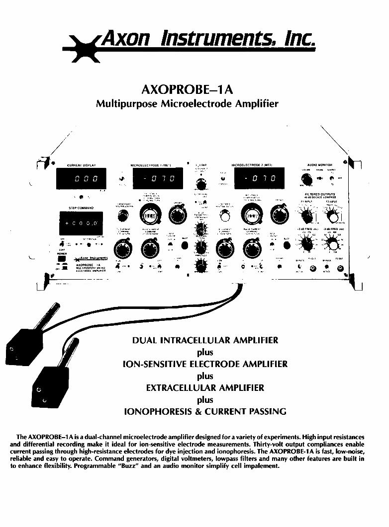
The AXOPROBE-1 A is a dual-channel microelectrode amplifier designed for a variety of experiments. High input resistances and differential recording make it ideal for ion-sensitive electrode measurements. Thirty-volt output compliances enable current passing through high-resistance electrodes for dye injection and ionophoresis. The AXOPROBE-1 A is fast, low-noise, reliable and easy to operate. Command generators, digital voltmeters, lowpass filters and many other features are built in to enhance flexibility. Programmable "Buzz" and an audio monitor simplify cell impalement.
HEADSTAGES
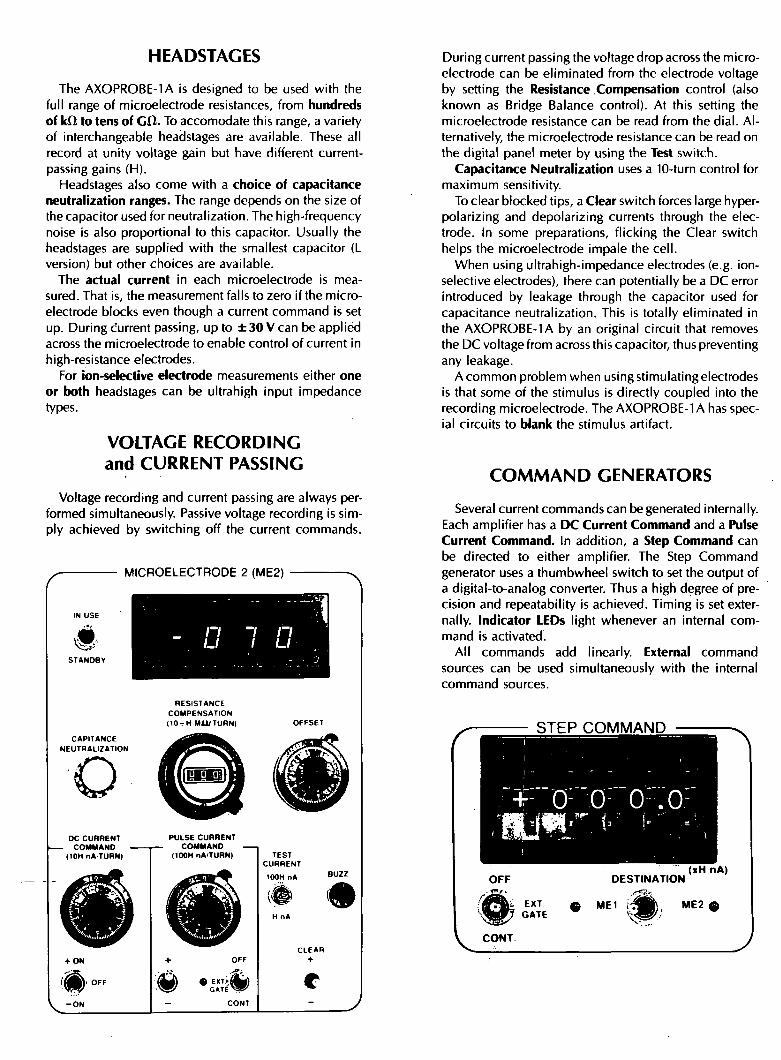
The AXOPROBE-1 A is designed to be used with the full range of microelectrode resistances, from hundreds of k n to tens of Cf t . To accomodate this range, a variety of interchangeable headstages are available. These all record at unity voltage gain but have different current-passing gains (H).
Headstages also come with a choice of capacitance neutralization ranges. The range depends on the size of the capacitor used for neutralization. The high-frequency noise is also proportional to this capacitor. Usually the headstages are supplied with the smallest capacitor (L version) but other choices are available.
The actual current in each microelectrode is measured. That is, the measurement falls to zero if the microelectrode blocks even though a current command is set up. During current passing, up to ± 3 0 V can be applied across the microelectrode to enable control of current in high-resistance electrodes.
For ion-selective electrode measurements either one or both headstages can be ultrahigh input impedance types.
VOLTAGE RECORDING and CURRENT PASSING
Voltage recording and current passing are always performed simultaneously. Passive voltage recording is simply achieved by switching off the current commands.
MICROELECTRODE 2 (ME2)
RESISTANCE COMPENSATION ( lOvH MU/TURNI
CAPITANCE NEUTRALIZATION
o DC CURRENT
- COMMAND (10H nA TURN)
.t-OM
PULSE CURRENT COMMAND
(100H nA/TURN)
W •^ii^
TEST CURRENT
«
During current passing the voltage drop across the microelectrode can be eliminated from the electrode voltage by setting the Resistance Compensation control (also known as Bridge Balance control). At this setting the microelectrode resistance can be read from the dial. Alternatively, the microelectrode resistance can be read on the digital panel meter by using the Test switch.
Capacitance Neutralization uses a 10-turn control for maximum sensitivity.
To clear blocked tips, a Clear switch forces large hyper-polarizing and depolarizing currents through the electrode. In some preparations, flicking the Clear switch helps the microelectrode impale the cell.
When using ultrahigh-impedance electrodes (e.g. ion-selective electrodes), there can potentially be a DC error introduced by leakage through the capacitor used for capacitance neutralization. This is totally eliminated in the AXOPROBE-1 A by an original circuit that removes the DC voltage from across this capacitor, thus preventing any leakage.
A common problem when using stimulating electrodes is that some of the stimulus is directly coupled into the recording microelectrode. The AXOPROBE-1 A has special circuits to blank the stimulus artifact.
COMMAND GENERATORS
Several current commands can be generated internally. Each amplifier has a DC Current Command and a Pulse Current Command. In addition, a Step Command can be directed to either amplifier. The Step Command generator uses a thumbwheel switch to set the output of a digital-to-analog converter. Thus a high degree of precision and repeatability is achieved. Timing is set externally, indicator LEDs light whenever an internal command is activated.
All commands add linearly. Externai command sources can be used simultaneously with the internal command sources.
STEP COMMAND
OFF DESTINATION (xH nA)
9 ME1 ' ^
ME2 Q
CONT
DIFFERENTIAL MEASUREMENT
^ C ^ C O M P _ ^ ^ ^
/ IN ENHANCE \ OUT NEUT
OFF MAX
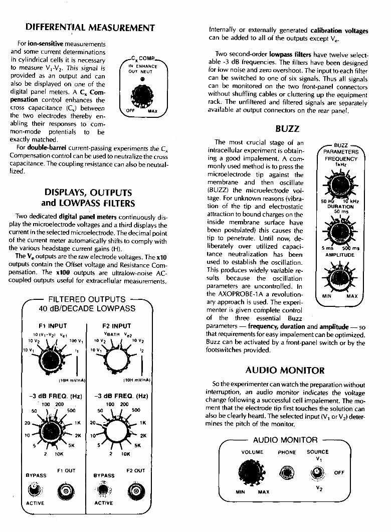
For ion-sensitive measurements and some current determinations in cylindrical cells it is necessary to measure V^-Vj. This signal is provided as an output and can also be displayed on one of the digital panel meters. A C, Compensation control enhances the cross capacitance (C^) between the two electrodes thereby enabling their responses to common-mode potentials to be exactly matched.
For double-barrel current-passing experiments the C^ Compensation control can be used to neutralize the cross capacitance. The coupling resistance can also be neutral-lized.
DISPLAYS, OUTPUTS and LOWPASS FILTERS
Two dedicated digital panel meters continuously display the microelectrode voltages and a third displays the current in the selected microelectrode. The decimal point of the current meter automatically shifts to comply with the various headstage current gains (H).
The Vg outputs are the raw electrode voltages. The xlO outputs contain the Offset voltage and Resistance Compensation. The xlOO outputs are ultralow-noise AC-coupled outputs useful for extracellular measurements.
— FILTERED OUTPUTS — 40 dB/DECADE LOWPASS
Fl INPUT 1 0 ( V , - V 2
(10H mV/nA)
-3 dB FREO. (Hz) 100 200
50 \ / 500
BYPASS
w ACTIVE
Fl OUT
:®i
F2 INPUT V B A T H
(10H mV/nA)
- 3 dB FREQ. (Hz) 100 200
50 \ / SOO
10K
BYPASS
ACTIVE
F2 0UT
Internally or externally generated calibration voltages can be added to all of the outputs except Vg.
Two second-order lowpass filters have twelve selectable -3 dB frequencies. The filters have been designed for low noise and zero overshoot. The input to each filter can be switched to one of six signals. Thus all signals can be monitored on the two front-panel connectors without shuffling cables or cluttering up the equipment rack. The unfiltered and filtered signals are separately available at output connectors on the rear panel.
/ — BUZZ /^PARAMETERS
FREQUENCY fkHz
BUZZ The most crucial stage of an
intracellular experiment is obtaining a good impalement. A commonly used method is to press the microelectrode tip against the membrane and then oscillate (BUZZ) the microelectrode voltage. For unknown reasons (vibration of the tip and electrostatic attraction to bound charges on the inside membrane surface have been postulated) this causes the tip to penetrate. Until now, deliberately over utilized capacitance neutralization has been used to establish the oscillation. This produces widely variable results because the oscillation parameters are uncontrolled. In the AXOPROBE-1 A a revolution- i MIN
ary approach is used. The experi- \^^ menter is given complete control of the three essential Buzz parameters — frequency, duration and amplitude — so that requirements for easy impalement can be optimized. Buzz can be activated by a front-panel switch or by the footswitches provided.
AUDIO MONITOR So the experimenter can watch the preparation without
interruption, an audio monitor indicates the voltage change following a successful cell impalement. The moment that the electrode tip first touches the solution can also be clearly heard. The selected input (V, or Vj) determines the pitch of the monitor.
MAX
AUDIO MONITOR VOLUME
^ f l ^
PHONE SOURCE
OFF
MIN MAX
GENERAL A third electrode can be used extracellularly to record
the bath potential. To compensate for potential shifts caused by changing the bath solution or temperature, the bath potential is subtracted from the potentials recorded by the two main electrodes.
A specially constructed low-radiation transformer eliminates the source of line-frequency noise (hum). The incoming line voltage is filtered to remove radio-frequency interference (RFI).
Strong emphasis has been placed on quality. Precision ten-turn potentiometers, reliable switches and gold-plated connectors are used throughout. Ultralow-drift operational amplifiers are used in all critical positions and ICs are socketted for easy maintenance. Detailed operator's and service manuals are provided.
FURTHER INFORMATION and ORDERING
The Specifications Sheet contains complete technical details and ordering information. Please call the factory for answers to any questions you may have.
Axon Instruments, Inc. 1437 Rollins Road
Burlingame, CA 94010 U.S.A.
Phone (415) 340-9988 Telex: 6771237
- ^
Axon Instruments, Inc. B-1
November 1986
AXOPROBE-1 A Multipurpose Microelectrode Amplifier
SPECIFICATIONS
Note: Numbered Hems are detailed in the TaUe.
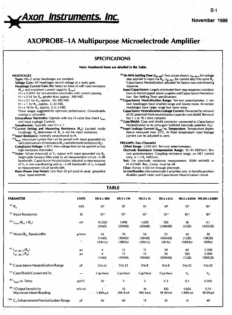
HEADSTAGES Types: HS-2 series headstages are standard. Voltage Gain: All headstages record voltage at a unity gain. Headstage Current Gain (H): Select on basis of cell input resistance
(Ri„) and maximum current capacity dmax)-H = x 0.0001 for ion-sensitive electrodes with current passing. H = x 0.01 for Rin greater than approx. 300 Mf l . H = x 0.1 for R,„ approx. 30-300 Mf l . H = X 1 for Ri„ approx. 3-30 Mi l . H = x 10 for Ri„ approx. 0.3-3 Mn. These ranges suggested for optimum performance. Considerable overlap Is allowable.
Extracellular Electrodes: Operate with any H value (but check Ip,,, and Input Leakage Current).
lonophoresis: Typically uses H = x 1. '"Current Setting and Measuring Resistance (RJ: Located inside
headstage. R , determines H. R is nof the input resistance. '''input Resistance: Inversely proportional to H. '•"'max: Maximum current that can be passed with input grounded via
indicated sum of cell resistance (Rin) and electrode resistance (R ). Compliance Voltage: ± 30 V. Max voltage that can be applied across
high-resistance electrodes. '*'Noise: Values measured at V^ output with input grounded via Re-
Single-pole lowpass filter used to set measurement circuit -3 dB bandwidth. Capacitance Neutralization adjusted so step response of Vj is non-oyershooting and so -3 dB bandwidth of v^ is equal to measurement circuit bandwidth.
Hum (Power Line Noise): Less than 20 )xV peak-to-peak, grounded input, input-referred.
'"10-90% Settling Time (fia_9o): Two values shown; f,o_,o,i, for voltage step applied to Input via R ; fro_9o.i for current step into same R . Capacitance Neutralization adjusted for fastest non-overshooting response.
Input Capacitance: Largely eliminated from step response considerations by bootstrapped power supplies and Capacitance Neutralization. See Settling Time specifications.
'"Capacitance Neutralization Range: Ten-turn potentiometer. L version headstages have smallest range and lowest noise. M version headstages have larger range but more noise.
Capacitance Neutralization Leakage Current: Prevented by removal of DC potentials from neutralization capacitor and shield. Removal has 1 s or 10 s time constant.
'"Case/Shield: Case and shield connector connected to Capacitance Neutralization or to unity-gain buffered electrode potential (V,.).
"' input Leakage Current die,),) vs. Temperature. Temperature depen-dance measured near 25°C. At fixed temperature input leakage current can be adjusted fo zero.
PREAMPS (Two Channels) Offset Range: ±500 mV. Ten-turn potentiometers. Electrode. Resistance Compensation Range: 10-^H MO/turn.' Ten-
turn potentiometers. Coupling resistance range, on ME1 control only, is I-HH2 Mfl/turn.
Test: For. electrode resistance measurement. 100H mV/Mfl or H mV/Mft. Res. Comp. must be off.
Clear: Forces ± 100 nA through electrode. In Use/Standby: Microelectrode 2 arnplifier only. In Standby piosltion
disables panel meter and Capacitance Neutralization circuit.
TABLE
PARAMETER
' " R„
'^' Input Resistance
'max (Rin + ^ Q )
Nolse(R„, Bandwidth)
V/(Re'
u(Re). ^10-90,
'*' Capacitance Neutralization Range
'•'' Case/Shield Connected To
'«'Ileal, vs. Temp
' " I Output Sensitivity Maximum Meter Reading
' " " Cx Enhancement/Neutralization Range
UNITS
MO
n
nA
(iVrms
t
us
pF
—
pA/°C
mV/nA
pF
HS-2 X 10M
W
10'"
10,000 (2Mn)
24 ( IMO)
(10kHz)
4 4
( I M n )
Oto22
CapNeut
30
1 1.999 |xA
40
HS-2X1M
10'
10"
1,000 (20Mn)
70 ( lOMn) (10kHz)
12 13
(lOMO)
Oto22
Cap Neut
3
10 199.9 nA
40
HS-2 X 11
10-
10" .
1,000 (20Mn)
54 (lOMO) (10kHz)
11 12
(lOMfl)
0 t o 8
CapNeut
3
10 199.9 nA
15
HS-2 X 0.1 L
10"
10"
100 (200Mn)
53 (looMn) (1kHz)
34 36
(lOOMfi)
0 t o 8
CapNeut
0.3
100 19.99 nA
15
HS-2 X 0.01 M
10'
10"
10 (2Gn)
40 ( IGf t )
(100Hz)
40 300
( IGf t )
0 to22
V ,
0.1
1,000 1.999 nA
15
HS-2M X 0.0001
10"
10"
0.1 (200Gft)
30 (lOCft) (10Hz)
2,000 3,000
(lOOGft)
Ofo22
Ve
0.005
0.1V 19.99 pA
40
B-2
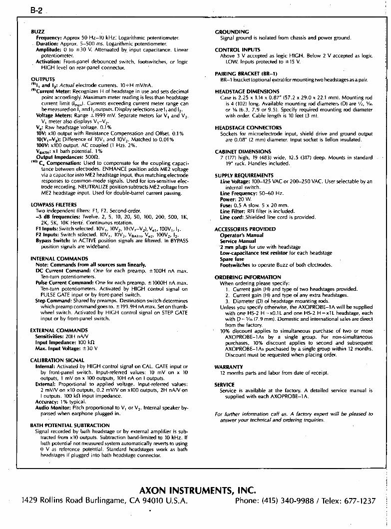
BUZZ Frequency: Approx 50 Hz-10 kHz. Logarithmic potentiometer. Duration: Approx. 5-500 ms. Logarithmic potentiometer. Amplitude: 0 to ±30 V. Attenuated by. input capacitance. Linear
potentiometer. Activation: Front-panel debounced switch, footswitches, or logic
HIGH level on rear-panel connector.
OUTPUTS " ' I , and 1^: /Acfoa/electrode currents. 10-^H mV/nA. ' "Current Meter: Recognizes H of headstage in use and sets decimal
point accordingly. Maximum meter reading is less than headstage current limit { l , ^ J - Currents exceeding current meter range can be measured on I, and I j outputs. Display selections are I, and l j .
Voltage Meters: Range ±1999 mV. Separate meters for V, and V j . V, meter also displays V i - V j .
V,: Raw headstage voltage. 0.1 % 10V: x io output with Resistance Compensation and Offset. 0.1 % 10(V,-Vj) : Difference of 10V, and lOVj. Matched to 0 .01% 100V: xlOO output. AC coupled (1 Hz). 2%. VgATH= x l bath potential. 1 % Output Impedances: SOOft.
(10) Q^ Compensation: Used to compensate for the coupling capacitance between electrodes. ENHANCE position adds ME2 voltage via a capacitor into ME2 headstage input, thus matching electrode responses to common-mode signals. Used for Ion-sensitive electrode recording. NEUTRALIZE position subtracts ME2 voltage from ME2 headstage input. Used for double-barrel current passing.
LOWPASS FILETERS Two independent filters: Fl , F2. Second-order. - 3 dB frequencies: Twelve. 2, 5, 10, 20, 50, 100, 200, 500, IK,
2K, 5K, 10K Hertz. Continuous rotation. Fl Inputs: Switch selected. 10V,, lOVj, 10(V,-Vj) , V^,, 100V,, I,. F2 Inputs: Switch selected. 10V,, lOVj, VBATH- '^e2' lOOVj, I j . Bypass Switch: In ACTIVE position signals are filtered. In BYPASS
position signals are wideband.
INTERNAL COMMANDS Note: Commands from all sources sum linearly. DC Current Command: One for each preamp. ±100H nA max.
Ten-turn potentiometers. Pulse Current Command: One for each preamp. ± 1000H nA max.
Ten-turn potentiometers. Activated by HIGH control signal on PULSE GATE input or by front-panel switch.
Step Command: Shared by preamps. Destination switch determines which preamp command goes to. ± 199.9H nA max. Set on thumbwheel switch. Activated by HIGH control signal on STEP GATE input or by front-panel switch.
EXTERNAL COMMANDS Sensitivities: 20H nAA' Input Impedance: 100 kft Max. Input Vbltage: ±30 V
CALIBRATION SIGNAL Intemal: Activated by HIGH control signal on CAL. GATE injjut or
by front-panel switch. Input-referred values: 10 mV on x 10 outputs, 1 mV on x 100 outputs, 10H nA on I outputs.
Extemal: Proportional to applied voltage. Input-referred values: 2 mVA' on xlO outputs, 0.2 mVA/ on xlOO outputs, 2H nAA 'on I outputs. 100 kf t Input impedance.
Accuracy: 1% typical. Audio Monitor: Pitch proportional to V, or V j . Internal speaker by
passed when earphone plugged in.
BATH POTENTIAL SUBTRACTION Signal recorded by bath headstage or by external amplifier Is sub
tracted from x io outputs. Subtraction band-limited to 10 kHz. If bath potential not measured system automatically reverts fo using 0 V as reference potential. Standard headstages work as bath headstages if plugged into bath headstage connector.
GROUNDING Signal ground is isolated fnjm chassis and power ground.
CONTROL INPUTS Above 3 V accepted as logic HIGH. Below 2 V accepted as logic
LOW. Inputs protected to ±15 V.
PAIRING BRACKET (BR-1) BR-1 bracket (optional extra) for mounting two headstages as a pair.
HEADSTAGE DIMENSIONS Case is 2.25 x 1.14 x 0.87" (57.2 x 29.0 x 22.1 mm). Mounting rod
is 4 (102) long. Available mounting rod diameters (D) are Vi, Vio or VB (6.3, 7.9 or 9.5). Specify required mounting rod diameter with order. Cable length is 10 feet (3 m).
HEADSTAGE CONNECTORS Sockets for microelectrode input, shield drive and ground output
are 0.08" (2 mm) diameter. Input socket is Teflon insulated.
CABINET DIMENSIONS 7 (177) high, 19 (483) wide, 12.5 (317) deep. Mounts in standard
19" rack. Handles included.
SUPPLY REQUIREMENTS Line VolUge: 100-125 VAC or 200-250 VAC. User selectable by an
internal switch. Line Frequency: 50-60 Hz. Power: 20 W. Fuse: 0.5 A slow. 5 x 20 mm. Line Filter: RFI filter is included. Line cord: Shielded line cord is provided.
ACCESSORIES PROVIDED Operator's Manual Service Manual 2 mm plugs for use with headstage Low-capacitance test resistor for each headstage Spare fuse Footswitches to operate Buzz of both electrodes.
ORDERING INFORMATION When ordering please specify:
1. Current gain (H) and type of two headstages provided. 2. Current gain (H) and type of any extra headstages. 3. Diameter (D) of headstage mouriting rods.
Unless you specify otherwise, the AXOPROBE-1 A wi l l be supplied with one HS-2 H = x0.1L and one HS-2 H = x l L headstage, each with D = Vif. (7.9 mm). Domestic and international sales are direct from the factory.
10% discount applies to simultaneous purchase of two or more AXOPROBE-1 As by a single group. For non-simultaneous purchases, 10% discount applies to second and subsequent AXOPROBE-1 As purchased by a single group within 12 months. Discount must be requested when placing order.
WARRANTY 12 months parts and labor from date of receipt.
SERVICE Service is available at the factory. A detailed service manual is
supplied with each AXOPROBE-1 A.
For further information cal l us. A factory expert wi l l be pleased to answer your technical and ordering inquiries.
AXON INSTRUMENTS, INC. 1429 Rollins Road Burlingame, CA 94010 U.S.A. Phone: (415) 340-9988 / Telex: 677-1237
c-1
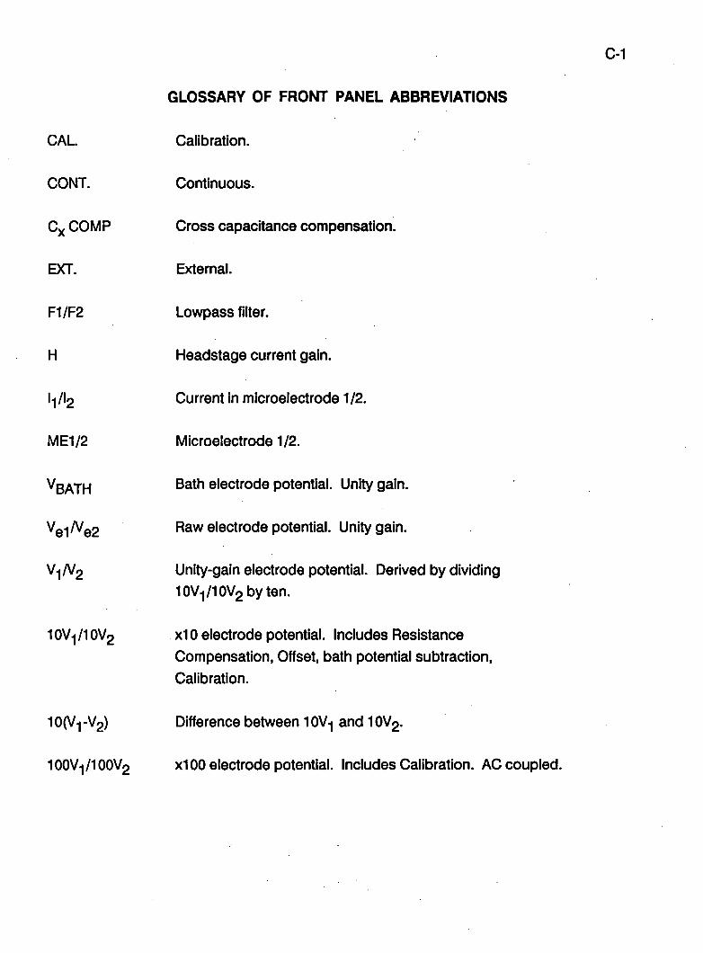
GLOSSARY OF FRONT PANEL ABBREVIATIONS
CAL.
CONT.
Cx COMP
EXT.
F1/F2
H
'l/'2
ME1/2
VBATH
Vel/Ve2
V1/V2
10V1/10V2
10(Vi-V2)
Calibration.
Continuous.
Cross capacitance compensation.
External.
Lowpass filter.
Headstage current gain.
Current in microelectrode 1/2.
Microelectrode 1/2.
Bath electrode potential. Unity gain.
Raw electrode potential. Unity gain.
Unity-gain electrode potential. Derived by dividing 10Vi/10V2byten.
xio electrode potential. Includes Resistance Compensation, Offset, bath potential subtraction, Calibration.
Difference between IOV1 and IOV2.
IOOV1/IOOV2 XlOO electrode potential. Includes Calibration. AC coupled.
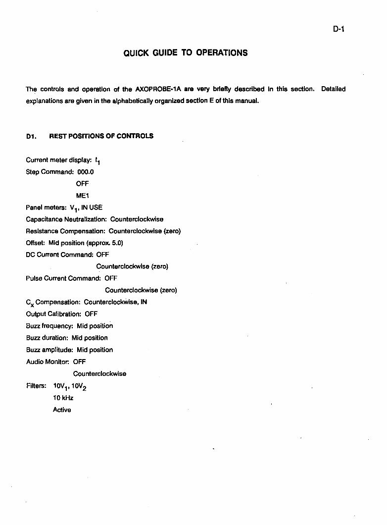
D-1
QUICK GUIDE TO OPERATIONS
The controls and operation of the AXOPROBE-1 A are very briefly described in this section. Detailed
explanations are given in the alphabetically organized section E of this manual.
D1. REST POSITIONS OF CONTROLS
Current meter display: l.|
Step Command: 000.0
OFF
ME1
Panel meters: V^, IN USE
Capacitance Neutralization: Counterclockwise
Resistance Compensation: Counterclockwise (zero)
Offset: Mid position (approx. 5.0)
DC Current Command: OFF
Counterclockwise (zero)
Pulse Current Command: OFF
Counterclockwise (zero)
C^ Compensation: Counterclockwise, IN
Output Calibration: OFF
Buzz frequency: Mid position
Buzz duration: Mid position
Buzz amplitude: Mid position
Audio Monitor OFF
Counterclockwise
Filters: lOV^.IOVg
10 kHz
Active
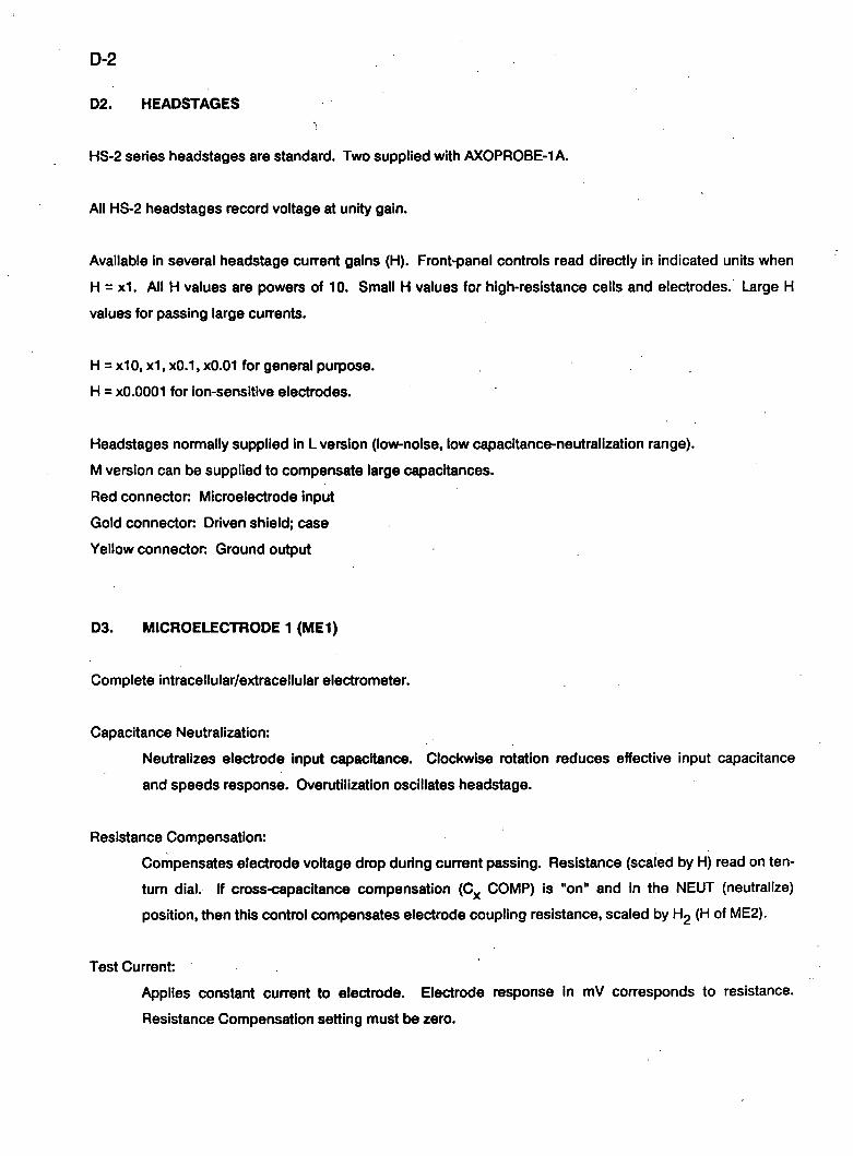
D-2
D2. HEADSTAGES
HS-2 series headstages are standard. Two supplied with AXOPROBE-1 A.
All HS-2 headstages record voltage at unity gain.
Available in several headstage current gains (H). Front-panel controls read directly in indicated units when
H = x1. All H values are powers of 10. Small H values for high-resistance cells and electrodes. Large H
values for passing large currents.
H = x10, x1, xO.1, xO.OI for general purpose.
H = xO.OOOl for ion-sensitive electrodes.
Headstages normally supplied in L version (low-noise, low capacitance-neutralization range).
M version can be supplied to compensate large capacitances.
Red connector Microelectrode input
Gold connector Driven shield; case
Yellow connector Ground output
D3. MICROELECTRODE 1 (ME1)
Complete intracellular/extracellular electrometer.
Capacitance Neutralization:
Neutralizes electrode input capacitance. Clockwise rotation reduces effective input capacitance
and speeds response. Overutilization oscillates headstage.
Resistance Compensation:
Compensates electrode voltage drop during current passing. Resistance (scaled by H) read on ten-
turn dial. If cross-capacitance compensation (0,^ COMP) is "on" and in the NEUT (neutralize)
position, then this control compensates electrode coupling resistance, scaled by H2 (H of ME2).
Test Current:
Applies constant current to electrode. Electrode response in mV corresponds to resistance.
Resistance Compensation setting must be zero.
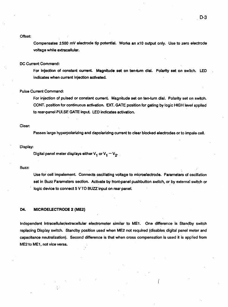
D-3
Offset:
Compensates ±500 mV electrode tip potential. Works an xlO output only. Use to zero electrode
voltage while extracellular.
DC Current Command:
For injection of constant current. Magnitude set on ten-turn dial. Polarity set on switch. LED
indicates when current injection activtrted.
Pulse Current Command:
For injection of pulsed or constant current. Magnitude set on ten-turn dial. Polarity set on switch.
CONT. position for continuous activation. EXT. GATE position for gating by logic HIGH level applied
to rear-panel PULSE GATE input LED indicates activation.
Clear
Passes large hyperpolarizing and depolarizing current to clear blocked electrodes or to impale cell.
Display:
Digital panel meter displays either V.| or V.| — V2.
Buzz:
Use for cell impalement. Connects oscillating voltage to microelectrode. Parameters of oscillation
set in Buzz Parameters section. Activate by front-panel pushbutton switch, or by external switch or
logic device to connect 5 V TO BUZZ input on rear panel.
D4. MICROELECTRODE 2 (ME2)
Independent intracellular/extracellular electrometer similar to ME1. One difference is Standby switch
replacing Display switch. Standby position used when ME2 not required (disables digital panel meter and
capacitance neutralization). Second difference is that when cross compensation is used it is applied from
ME2 to ME1, not vice versa.
D-4
D5. BUZZ PARAMETERS:
For optimization of headstage oscillation used to assist impalement. Frequency, Duration and Amplitude of
oscillation independently set.
D6. FILTERED OUTPUTS
Two independent two-pole filters. One of six output signals can be selected for each filter. Twelve —3 dB
cutoff frequencies can be selected. Bypass/Active switch determines whether signal is filtered (active
position) or widet}and (filter bypassed).
D7. C^ COMP
IN: Enhances capacitance coupling of V2 into V.|. Speeds ME1 response to common signals so that
common signals are recorded identically by ME1 and ME2. Useful for ion-sensitive electrode
recording.
OUT: Neutralizes resistance and capacitance coupling of V2 into V.|. Useful for current passing through
one ban-el of a double-ban-el electrode.
D8. OUTPUT CAL
Adds a 100 mV signal to current outputs, xlO and xlOO voltage outputs. Input-referred values are 10H nA,
10 mV and 1 mV respectively. CONT. position for continuous activation. EXT. GATE position for gating by
logic HIGH level applied to rear-panel CAL GATE input. Additional calibration signals separately generated
by applying a signal to the EXT. CAL SIGNAL input on the rear panel.
D9. CURRENT DISPLAY
Meter displays average current. Decimal point automatically placed to suit H. Display is in nA for H = x l ,
xO.l.xO.OI; pAforH = x0.0001; ^ f o r H = x10. Display 11 or I2.
D-5
DIG. STEP COMMAND
D/A converter generates precision command voltages. Destination switch selects either MEI or ME2 to be
target for command. Thumbwheel switch sets magnKude with 0.05% resolution. Magnitudes are scaled by
H. CONT position for continuous activation. EXT. GATE position for activation by logic HIGH level applied
to rear-panel STEP GATE input.
D11. AUDIO MONITOR
Pitch of audible tone depends on potential of selected Input (V.| or V2). Potentiometer sets volume.
Earphone can be plugged into phone jack. If so, speaker is disabled.
D12. BATH POTENTIAL
Use a low-resistance microelectrode with an HS-2 headstage to record potential of bath solution (Vgy^ji^).
This potential is sutjtracted from 10V.| and lOVj outputs. If not required, do not plug headstage into rear-
panel connector. Vg^^-p^ recorded t)y outside equipment can be subtracted by connecting to EXT. Vp^^ji.
connector
D13. INPUTS AND OUTPUTS
Located on rear-panel, but Fl OUT and F2 OUT repeated on front-panel.
F1,F2 outputs:
Filtered outputs.
VQ output
Raw electrode potential.
10V output:
Modified electrode potential. xlO gain. Includes Offset Resistance Compensation, CAL and bath
potential.
D-6
10(V^-V2) output:
Difference signal.
100V output:
AC-coupled (1 Hz) electrode potential x100 gain. Includes CAL
V B A T H °"*P"t= Potential recorded by bath electrode.
I output
Electrode current.
Logic Levels:
Over 3 V accepted as logic HIGH. Below 1 V accepted as logic LOW. ±15 V safe operating range.
Step Gate input:
Logic HIGH activates Step Command.
Pulse Gate input
Logic HIGH activates Pulse Current.
100 mV CAL Gate input:
Logic HIGH activates 100 mV OUTPUT CAL
EXT. CAL Signal input:
Voltage on this input converted into proportional calibration signal.
EXT. ME Command input
Voltage on this input converted into proportional current
EXT. Vgy^ji^ input:
Bath potential recorded by outside equipment subtracted from 10V outputs.
V.| Blank Gate Input:
Logic HIGH causes Vg.| to be sampled and held. Used for stimulus artifact rejection.
D-7
Buzz ME input:
Logic HIGH on this input activates Buzz.
+5V output:
Used with footswitches to generate logic HIGH level for Buzz. Protected by 150 ohm series resistor.
E-1
DETAILED GUIDE TO OPERATION
The controls and operation of the AXOPROBE-1 A are described In this section. The
topics are arranged in alphabetical order.
E-2
AUDIO MONITOR
The audio monitor is a voltage controlled oscillator (VCO) that drives a small speaker A switch is used to
select V.| or V2 as the control voltage (V^). As V^ varies, a so too does the pitch of the audio tone.
When VQ = 0 the frequency is about 2.25 kHz. This frequency drops by approximately 3 octaves as V^
decreases to-100 mV.
The Audio Monitor enables changes in the electrode potential to be recognized without having to look at the
oscilloscope or panel meters. Thus one can detect a successful cell impalement while still looking through
the microscope. There is also an abrupt change in tone when a new electrode first touches the solution.
Thus the electrode can be lowered towards the preparation very rapidly and stopped as soon as the tone
change indicates contact with the solution.
The volume control on minimum makes the tone inaudible. The volume control can be left in its usual
position and the Audio Monitor switched off by using the center position of the input-selector switch.
An earphone can be plugged into the phone jack provided. This disables the speaker

E-3
BATH PROBE
In certain experimental circumstances it is desirable to make all voltage measurements relative to a
reference point in the bathing solution rather than relative to ground. (These conditions may include
precision measurements during changes of temperature or Ion content of the saline, or cases of restricted
access from the extracellular space to the grounding point.)
All measurements are normally made relative to the system ground. However, if a unity-gain headstage is
plugged into the rear-panel Bath Headstage connector, measurements by both MEI and ME2 are made
relative to the potential recorded by this headstage. The bandwidth of the bath potential is limited to 10 kHz
t}efore it is subtracted from the potentials recorded by ME1 and ME2. The bath microelectrode cannot be
used for current passing.
If there is no unity-gain headstage plugged into the Bath Headstage connector, a reference potential from
an extemal amplifier can be subtracted by connecting It to the EXT. Vg^-p^ connector
E-4
BLANKING
A common problem when using stimulating electrodes is that some of the stimulus is directly coupled into
the recording microelectrode. The best way to minimize or even eliminate this artifact is at the source, by
using small stimuli, isolated stimulators, placing an earthed shield l}etween the stimulating electrodes and
the microelectrodes, etc. Often, though, it is not possible to reduce the artifact to manageable levels.
Artifact pickup is particulariy apparent on the xlOO output because the capacitor used for AC coupling
acquires a net charge from the artifact. This charge may take several hundred milliseconds to decay.
The AXOPROBE-1 A can circumvent the effects of the stimulus artifact by Blanking. At the moment the logic
level of the V.| BLANK GATE input goes HIGH the value of V.| is sampled and saved. For the duration of the
HIGH signal, this saved value is used instead of the actual potential.
E-5
BUZZ
When the Buzz switch is pressed, an oscillating voltage Is applied to the microelectrode via a capacitor in
the headstage. (This capacitor is normally used for capacitance neutralization.)
If this is done while the tip of the microelectrode Is pressing against the cell membrane, the oscillation will
often help the microelectrode impale the cell. The mechanism Is unknown, but it may involve attraction
between the charge at the tip of the microelectrode and bound charges on the inside of the membrane.
To see the oscillating microelectrode voltage, look at V^ without filtering. The Buzz waveform consists of an
altemating series of positive and negative spikes which decay substantially when the oscillation frequency
is low.
The Duration control govems the overall period of the burst of oscillation. The pushbutton Buzz switches
are debounced. That is, bursts cannot be accidentally triggered when the button is released.
The Frequency control govems the frequency of the oscillation.
The Amplitude control govems the amplitude of the oscillation. This control is linear The amplitude is
attenuated t)y the electrode capacitance when it is more that a few pF.
The Buzz Parameter controls are shared by the two electrodes. However, the Buzz oscillation only goes to
the electrode whose Buzz button is pressed.
Buzz can be activated by the front-panel pushbutton switches. It can also be activated biy applying a logic
HIGH voltage to the Buzz jack on the rear panel. The logic HIGH voltage can arise from' a switch (such as
the footswitch provided) used to connect +5 V (red jack) to the Buzz input (violet jack), or by using an
external logic device.
E-6
CALIBRATION SIGNAL
A calibration signal can be simultaneously superimposed on all of the voltage and current outputs except
A +100 mV intemally generated calibration voltage can be activated by switching the front-panel switch to
the CONT. position. With the switch in the EXT. GATE position the -i-lOO mV calibration voltage is off unless
a logic HIGH level is applied to the rear-panel 100 mV CAL GATE input. The OFF position disables the
extemal logic command.
The -I-l 00 mV calibration voltage is added to the outputs. The input-referred values depend on the gain of
each output.
A calibration voltage proportional to an extemal signal can be added to the output by applying the extemal
signal to the EXT. CAL SIGNAL input. The voltage appearing on the outputs will be 20 mV per volt of
extemal signal. Thus the input-referred calibration voltages will be 2 mV/V on the 10V outputs, 0.2 mV/V on
the 100V outputs, and 2H nA/V on the I outputs.
E-7
CAPACITANCE NEUTRALIZATION AND INPUT CAPACITANCE
The Capacitance (C|p) at the input of the headstage amplifier is due to the capacitance of the amplifier input
itself (C|pi) plus the capacitance to ground of the microelectrode and any connecting lead (Cj^2)- ^in
combined with the microelectrode resistance (R^) acts as a lowpass filter for signals recorded at the tip of
the microelectrode. Two techniques may be used to increase the recording bandwidth.
(1) Primary
A special technique is used in the headstages to keep the contribution to Cj^ from the input amplifier as
small as possible. This consists of adding the input signal voltage to the power supply voltages used by the
input stages. This technique, known as bootstrapping, fixes the voltage drop across C|^.| to a constant
value thereby preventing current flow through C^ . . The effective value of Cj^.| is thus reduced to well
t>elow its real value.
(2) Secondary
A commonly used technique known as capacitance neutralization is used to negate Cjp2 and the effective
remnant of C|p.|. The capacitance neutralization circuit attempts to inject into the headstage input a current
which it anticipates will be required to charge and discharge Cj^ during signal changes. To use the
capacitance neutralization circuit the voltage response to a current step should be otjserved on an
oscilloscope. Advance the capacitance neutralization control as far as possible without introducing
overshoot in the step response. This setting is optimal for current passing and is also optimal for recording
potentials at the tip of the microelectrode.
It is important to recognize that the capacitance neutralization circuit is not more than 90% effective even for
ideal microelectrodes. This is because of the finite frequency responses of the headstage amplifiers and
the capacitance neutralization circuit, and also because C|^ does not behave ideally as a linear lumped
capacitor Consequently, the amount of Cj^ that the circuit must neutralize should be kept as small as
possible. To this end, avoid using long lengths of shielded cable to connect the microelectrode to the
input. If possible, plug the microelectrode holder directly into the input. Use shallow bathing solutions.
Avoid having grounded objects near the electrode. Do not ground the headstage case.

E-8
If metal objects (such as the microscope) must t>e very near the electrode, they may t>e disconnected from
ground and connected to the gold shield socket in the headstage. This technique may improve the
microelectrode response speed.
See also the section titled Microelectrodes for Fast Settling.
E-9
CLEAR
There is one Clear switch for each microelectrode. It Is used to pass up to ±1000H nA through the
microelectrode. "+" and "-" correspond to depolarizing and hyperpolarizing currents respectively. The Clear
switch is used for two purposes:
(1) When the microelectrode tip resistance goes high this condition can often be cleared by rapidly
toggling the Clear switch from + to -. Because of the large current passed this should only be done
extracellulariy.
(2) Sometimes microelectrode tips press against the cell membrane but fail to penetrate. A quick flick
of the Clear switch will often force the microelectrode to penetrate. Whether to use a
hyperpolarizing or depolarizing current depends on the preparation and must be determined by trial
and en-or Like Buzz, the mechanism for impalement is unknown.
E-10
COMMAND GENERATORS
Current commands can l>e obtained from the intemal Step Command generator, from the intemal DC
Command generators, from the internal Pulse Command generators, and from extemal sources.
All commands are scaled by the headstage current gain (H). Depolarizing commands are indicated by "+",
hyperpolarizing commands by "•".
The durations of the internal commands are either continuous, or gated by extemal logic HIGH levels used
to activate the commands.
Step Command Generator
The Step Command generator is shared by the two microelectrode amplifiers. Use the Destination switch
to direct the command to MEI or ME2.
The current indicated on the thumbwheel switch (scaled by H) is passed through the selected
microelectrode when the front-panel switch is in the CONT. position. With the switch in the EXT. GATE
position the command is off unless a logic HIGH level is applied to the rear-panel STEP GATE input. The
OFF position disables this extemal gating.
The maximum command which can be set on the thumbwheel switch is 199.9H nA. An LED corresponding
to the selected microelectrode lights up when the Step Command is activated. When rotating the
thumbwheel switch, be decisive. If the switch is rotated slowly the output will momentarily fall to zero as the
switching contacts pass through an open-circuit state.
DC Current Command
The current indicated on the ten-turn dial is passed through the microelectrode when the switch is in the
+0N or -ON position. The DC Current Command cannot be gated on and off by extemal logic signals. An
LED illuminates when the command is on. The maximum DC Current Command is 100H nA
I
E-11
Pulse Current Command
The current indicated on the ten-turn dial is passed through the microelectrode when the activation switch
is in the CONT. position. With the switch in the EXT. GATE position the command is off unless a logic HIGH
level is applied to the rear-panel PULSE GATE input. The OFF position disables this extemal activation. An
LED illuminates when the command is on. Polarity is set on a separate switch.
The maximum Pulse Current command is 1000H nA. There may be a small residual current command
whem the dial indicates zero. Switching to the OFF position will eliminate this residual command.
External Command Inputs
Two extemal command inputs are provided. These are for setting the current in MEI (EXT. MEI
COMMAND) and the current in ME2 (EXT. ME2 COMMAND). These extemal commands are active
simultaneously with the internal command generators. The sensitivity is 20H nA per volt of extemal signal.
The extemal command inputs are DC connected. Therefore, any deviation from zero volts in the extemal
signal source while it is in its "off" state will cause a DC current to flow in the electrode.
This can t>e avoided by using:
(1) A very high-quality external source which puts out a true zero voltage level in its off state or which
can be trimmed to do so.
(2) An isolated extemal source.
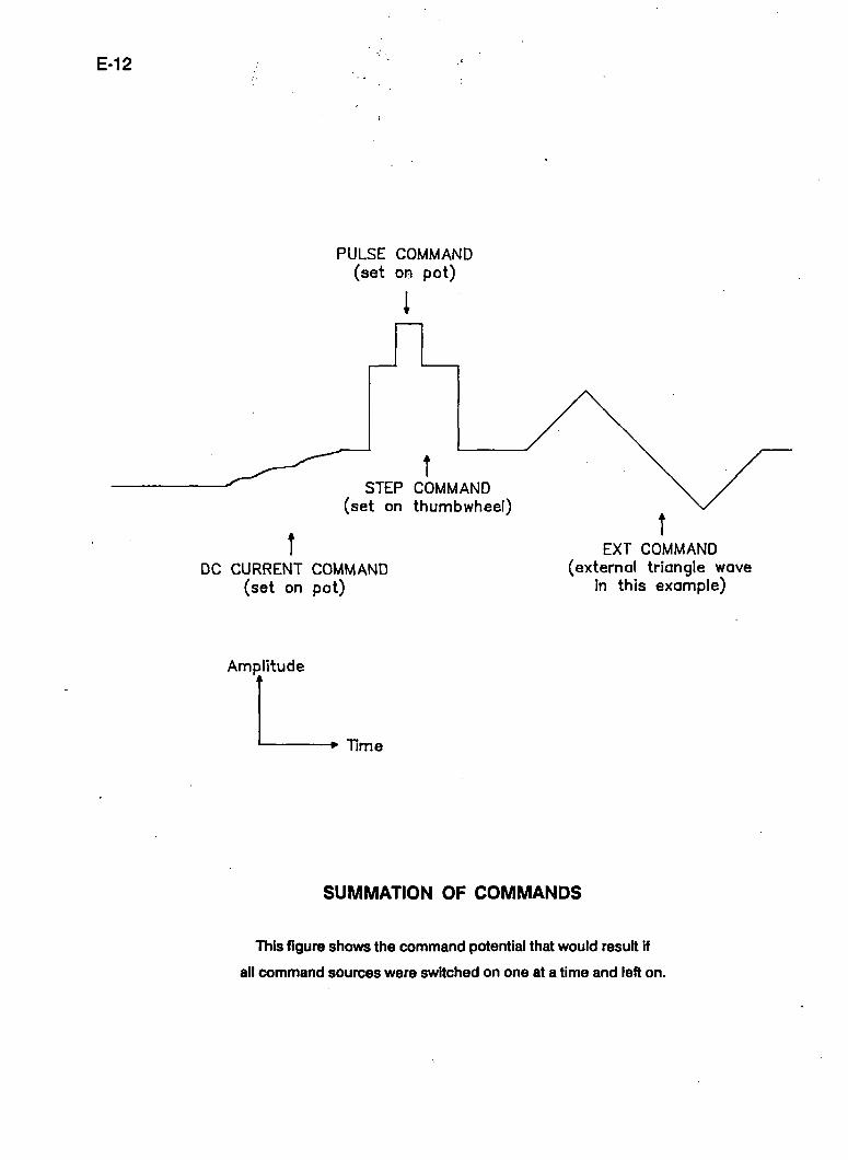
Mixing Commands | I I
Complex command waveforms can i)e generated by appropriately mixing the Step Command, the DC
Command, the Pulse Command and the Ext. Command. For example, the command waveform in the
following figure can be used to establish the current injected into MEI by setting the Destination switch to
the MEI position and using the MEI DC Command, the Step Command, the Pulse Command and the Ext.
MEI Command input.
E-12
PULSE COMMAND (set on pot)
STEP COMMAND (set on thumbwheel)
DC CURRENT COMMAND (set on pot)
EXT COMMAND (external triangle wave
in this example)
Amplitude
Time
SUMMATION OF COMMANDS
This figure shows the command potential that would result if
all command sources were switched on one at a time and left on.
E-13
CURRENT MEASUREMENT
The actual current through each microelectrode is independently measured. If the electrode blocks, the
measured current falls to zero even though a current command may exist
The current output is proportional to the voltage drop across a resistor (R^) Inside the headstage. The value
of RQ depends on the headstage current gain (H). Thus the current output scaling depends on H. It Is
lO + HmV/nA
E-14
Cjj COMP
The Cx COMP control is used to compensate microelectrode 1 for voltage transients occurring in
microelectrode 2. There are two modes of operation:
1) ENHANCEMENT: for ion-sensitive electrode recording
When the differential signal WQ/yW^ is recorded there is often a common-mode signal on both electrodes.
For example, when ion concentrations are measured the signal of interest is the difference between the
signals recorded by the ion-sensitive electrode (MEI) and the reference electrode (ME2). If the electrode
pair is intracellular both electrodes will record changes in membrane potential.
Unless the response speeds of the two electrodes are identical there will be a transient in the differential
signal due to imperfect cancellation of the common-mode signal (membrane potential).
The primary means of eliminating this transient is to try to match the electrode response speeds. Use the
Capacitance Neutralization controls to speed up the slower electrode and to slow down the faster electrode.
In addition, consider using a high-resistance electrode for the reference (e.g. a neutral-resin electrode).
When the two response speeds cannot be matched this way the C^ COMP control can help. This control
enhances the effective coupling capacitance (C ) from ME2 into MEI. This speeds up the MEI response to
common-mode signals so that common-mode signals are recorded identically by MEI and ME2. Thus the
transient in the differential signal is eliminated. Note that the speed for recording differential signals is not
improved.
2) NEUTRALIZATION: for double-barrel current passing
In some experiments, one barrel (ME2) of a double-t)arrel microelectrode is used for current-passing while
the other bane\ (ME1) is used to record the voltage response. Neglecting complications, this technique is
preferrable to the more usual one of using a single-barrel electrode for tioth tasks t>ecause fluctuations in
the electrode resistance during current passing do not affect the recorded potential.
There are two complications which reduce the usefulness of the double-tiarrel technique. These
are: 1) transient coupling through the coupling (or cross) capacitance (C^), and 2) DC coupling through the
coupling (or cross) resistance (R ) (see Rgure at the end of this section).
E-15
Transient Coupling
When a current step is applied to the ME2 twirrei, a voltage transient couples through the capacitance (C^)
ofthe separating glass wall into the MEI barrel. The C^ COMP potentiometer can be used to eliminate this
transient. First, pull the knob to select NEUTRALIZE mode. Second, while a repetitive cun^nt step is being
applied to ME2, rotate the C^ COMP potentiometer until the transient on 10V.| is eliminated.
Note that this control wori<s in one direction only. It operates by injecting a compensating current into MEI
derived from the voltage in ME2.
Decoupl ing
The coupling resistance (R^) is pooriy named. It is actually a fraction of the ME2 resistance whose voltage
drop is measured by MEI. This voltage drop is proportional to R^ and l2>
The MEI Resistance Compensation potentiometer can be used to eliminate this transient. When the C^
COMP control is in the NEUTRALIZE position, an LED lights to indicate that the MEI Resistance
Compensation is reconfigured to compensate the MEI voltage for the ME2 current. While a repetitive
current is t>eing applied to ME2, rotate the MEI Resistance Compensation potentiometer until the steady-
state step on 10V.| is eliminated.
E-16
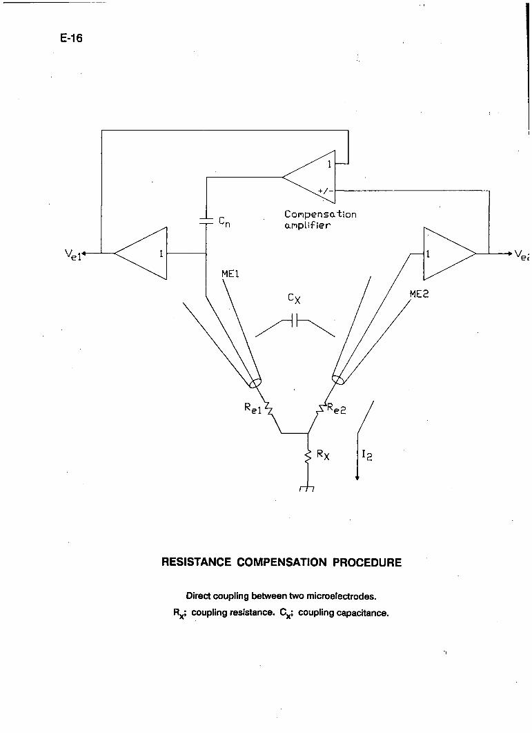
V„i*
Conpensation anpl i f ie r
RESISTANCE COMPENSATION PROCEDURE
Direct coupling t>etween two microelectrodes.
R ; coupling resistance. C^; coupling capacitance.
E-17
GROUNDING AND HUM
A perennial bane of electrophysiology is line-frequency pickup (noise), often referred to as hum. Hum can
occur not only at the line frequency but also at multiples of K.
The AXOPROBE-1 A has inherently low hum levels (less than 20 M>V peak-to-peak). To take advantage of
these low levels great care must be taken when integrating the AX0PR0BE-1A into a complete recording
system. The following procedures should be followed.
(1) Only ground the preparation bath by directly connecting it to the yellow ground connector on
the ME1 headstage.
(2) Place the AXOPROBE-1 A in a position in the rack where transformers in adjacent equipment are
unlikely to radiate into Its electronics. The most sensitive part of the AXOPROBE-1 A electronics is
the right-hand half of the bottom side looking from the front
(3) Initially make only one connection to the AXOPROBE-1 A. This should be to the oscilloscope from
the F l , Vg.| or 10V.| outputs. Ground the MEI headstage input to the yellow MEI ground
connector After verifying that the hum levels are low, start increasing the complexity of the
connections one lead at a time. Leads should not be draped near transformers located inside other
equipment. In desperate circumstances the continuity of the shield on an offending coaxial cable
can be broken.
(4) Try grounding auxiiliary equipment fi-om a ground distribution bus. This bus should be connected
to the AXOPROBE-1 A via the yellow banana (4 mm) socket on the rear panel. This socket is
connected to the AXOPROBE-1 A's signal ground (i.e. the outer conductors of all the BNC
connectors). The signal ground in the AX0PR0BE-1A is isolated from the chassis and power
ground.
(5) If more than one headstage is used, all the headstage cables should run from the AXOPROBE-1 A to
the preparation in a bundle. The bundle can be formed either by gently twisting the cables together
or by loosely tying them together

E-18
(6) Experiment While hum can be explained in theory (e.g. direct pickup, earth loops), in practice the
ultimate theory is the end result Following the rules above is the t}est start. The final hum level can
often be kept to less than 100 ^V peak-to-peak referred to V^. One technique that should not be
used to reduce the hurri is the delicate placement of cables so that a number of competing hum
sources cancel out. Such a procedure is too prone to accidental alteration.
E-19
HEADSTAGES
The headstage buffers the high impedance of the microelectrode, making the potential recorded by the
microelectrode available to the rest of the circuitry. K also provides the means for injecting cun^nt into the
microelectrode and for neutralizing the input capacitance.
The standard headstages for the AXOPROBE-1 A are the HS-2 series.
The Meaning of H
A precision resistor (R^) inside the headstage sets the headstage curent gain (H). Larger H values
correspond to smaller R^ values. The particular value of H used affects the Resistance Compensation
range, the sensitivity to current commands, the sensitivity of the current monitors, the input resistance and
the input leakage current. The effects on the control ranges (see Table 1) are clearty marked on the front
and rear panels, and since they always appear in multiples of 10 they are easy to calculate. The effects on
headstage performance are listed in the table in the specifications.
Which Headstage to Use
The H value required depends on the typical Input resistances (Rj^) of your cells. The recommended H
values are in Table 1.
E-20
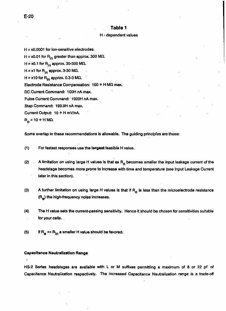
Table 1 H - dependent values
H = xO.0001 for ion-sensitive electrodes.
H = xO.01 for Rj^ greater than approx. 300 Mil.
H s xO.1 for Rj^ approx. 30-300 Mfl.
H = x l for Rj^ approx. 3-30 Mil.
H = x10 for Rj^ approx. 0.3-3 Md.
Electrode Resistance Compensation: 100-i-H Mfl max.
DC Current Command: lOOHnAmax.
Pulse Current Command: lOOOHnAmax.
Step Command: 199.9HnAmax.
Cun-ent Output: 10 + HmV/nA
RQ = 10-!-HMfl.
Some overiap in these recommendations Is allowable. The guiding principles are these:
(1) For fastest responses use the largest feasible H value.
(2) A limitation on using large H values is that as R^ becomes smaller the input leakage current of the
headstage becomes more prone to increase with time and temperature (see Input Leakage Current
later in this section).
(3) A further limitation on using large H values is that if RQ is less than the microelectrode resistance
(Rg) the high-frequency noise increases.
(4) The H value sets the current-passing sensitivity. Hence it should t x chosen for sensitivities suitable
for your cells.
(5) If Rg » R|p a smaller H value should be favored.
Capacitance Neutralization Range
HS'2 Series headstages are available with L or M suffixes permitting a maximum of 8 or 22 pF of
Capacitance Neutralization respectively. The increased Capacitance Neutralization range is a trade-off
E-21
against microelectrode noise. The HS-2L has the lowest noise, close to the theoretically predicted thermal
noise of the electrode. The HS-2M has about 20% extra noise.
Headstage Connectors
There are three tefion-insulated 2 mm (0.08 inch) sockets in the headstage (see Figure at end of this
section). These are standard-diameter sockets. i
1. Microelectrode Input Connectoir
The red socket is the microelectrode input. The connection between the microelectrode and this socket
should be kept as short as possible. Two excellent methods are to:
(i) Solder a silver/silver-chtoride wire directly to one of the 2 mm plugs supplied. Use the wire
/ to connect to the microelectrode which can be supported on a separate mounting.
(ii) For greater mechanical stability, use an HL-2 series microelectrode holder form Axon
Instruments.
(iii) Plug a standard microelectrode holder (2 mm plug) directly into the input socket The teflon
input socket should allow enough clearance for most standard holders.
(iv) Use a BNC-type microelectrode holder This requires an HLB-2 adaptor from Axon
Instruments.
2. Shield Drive Connector
The Shield drive (gold socket) is connected to the gold-plated socket and to the case. The drive is
protected against continuous short circuits,, however for best frequency response the ciase must not be
grounded. In general, this necessitates using an insulated mounting for the headstage (such as the rod
provided).
The shield connection is provided primarily for driving the shield of microelectrodes prepared for deep
immersion (see notes in Microelectrodes for Fast Settling Section). It may also be used for driving metal
objects near the input, or even the hutch in which the preparation is housed. It can be used for driving the
shield of a coaxial cable used to connect the microelectrode to the input, although it is not recommended
E-22
that the microelectrode be connected in this way (see below), if not used, the shield socket is simply left
^ unconnected. -'•
There are two reasons why we do not recommend using shielded cable to connect the microelectrode to
the headstage:
1) Shielded cables add signiflcant input capacitance. The shield drive circuit rhostly removes the
effect of this capacitance on electrode response speed. However, fi-om a noise point of view the
capacitance remains and causes an increase in high-frequency electrode noise.
2) The leakage resistance of shielded cable can degrade the Input resistance when used with ion-
sensitive and other high-impedance electrodes. If shielded cable Is used it should have teflon as
the insulating material between the shield and the inner conductor
To optimize the response speed of low and medium impedance electrodes (up to approx. 300 Mfl) when a
driven shield is used, the shield of headstages with H = 0.1 and larger is driven from the capacitance
neutralization circuit To optimize the headstage input resistance when a driven shield is used, the shield of
headstages with H = 0.01 and smaller is driven from the output of the unity-gain buffer Inside the headstage.
If a shielded cable is being used and unusual electrode responses are otiserved, try disconnecting the
shield.
3. Ground Output Connector
The yellow ground socket of the MEI headstage is used for earthing the preparation. Using this
connection as the preparation ground minimizes hum.
Tip Potentials - Detection
During the passage of current the tip potentials of many electrodes change. Changes in tip potential are
indistinguishable from the membrane potential and can therefore represent a serious source of error To
prevent this error the following checks should t>e made.
(1) While the microelectrode is outside the cell, set the ofteet to zero. Pass a constant current into the
bath for about 10 seconds. The current magnitude should t>e the same as the maximum sustained
current likely to be passed during the experiment. When the current is switched off the recorded
E-23
potential should retum to zero within a few milliseconds at most Some electrodes either retum
very slowly to zero potential, or not at all. These electrodes should be discarded.
(2) Once the experiment is in progress occasionally check the resistance of the microelectrode.
Changes in tip potential are usually accompanied by changes in electrode resistance.
Tip Potentials - Prevention
Not much can be done to prevent tip potentials from changing but the following may t>e helpful.
(1) Sometimes the slow changes in tip potentials are worse when standard microelectrode holders with
an emfc>edded AgCI pellet are used instead of an Ag/AgCI wire. Some holders are alright while
other ostensibly identical holders are not. Therefore holders should be tested and selected.
The variability of the tip potentials may In some way be related to pressure developed when the
microelectrode is pressed Into the holder A narrow hole drilled into the side of the holder to relieve
pressure might help.
(2) Using filling solutions with low pH, or adding small concentrations of polyvalent cations like Th ,
may reduce the size of the tip potential (Pun/es, 1981) and therefore the magnitude of any changes.
Interchangeability
Any unity-gain headstage in the HS-2 series can be used for MEI or ME2. The equipment will not be
damaged if headstages are exchanged while the AXOPROBE-1 A is switched on.
Cleaning
To clean salt spills fi-om the input connectors wipe with a damp cloth. Avoid spilling liquids on the
headstage.
E-24
Input Leakage Current and How to Trim it to Zero
All DC-connected systems suffer fi-om the problem of drift. With changes in temperature and the passage of
time, the DC offsets of all semiconductor devices can drift by many millivolts away from their initial values.
The major worry in a microelectrode system is that the cumulative effects of drift in various parts of the
circuit may lead to the development of a DC offset across the resistor (R^) used to set H. As a result, an
undesirable DC leakage current is injected into the microelectrode.
Careful consideration to this problem has t)een applied throughout the design of the AXOPROBE-1 A and
the overall DC offset has been made as insensitive as possible to drift in the Integrated circuits. As well,
special low<irift integrated circuits have been used in all critical positions. The magnitude of the DC
leakage current Increases with H. This normally introduces no greater error in the DC offset voltage
developed across the microelectrode or the cell membrane because larger H values are usually used with
lower-resistance cells and microelectrodes.
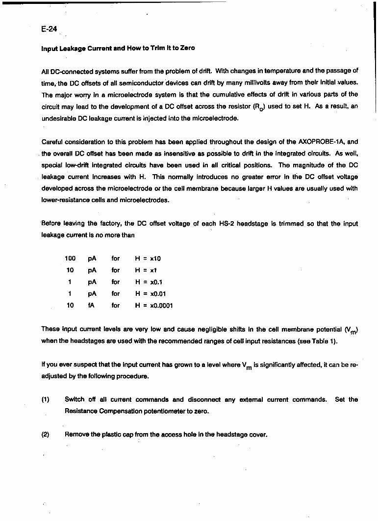
Before leaving the factory, the DC offset voltage of each HS-2 headstage is trimmed so that the input
leakage current Is no more than
100 pA for H = x io
10 pA for H = x l
1 pA for H = xO.1
1 pA for H = xO.01
10 fA for H = xO.0001
These Input current levels are very low and cause negligible shifts in the cell membrane potential (V^)
when the headstages are used with the recommended ranges of cell input resistances (see Table 1).
If you ever suspect that the input current has grown to a level where V,^ is significantly affected, it can be re
adjusted by the following procedure.
(1) Switch off all current commands and disconnect any extemal current commands. Set the
Resistance Compensation potentiometer to zero.
(2) Remove the plastic cap from the access hole in the headstage cover
E-25
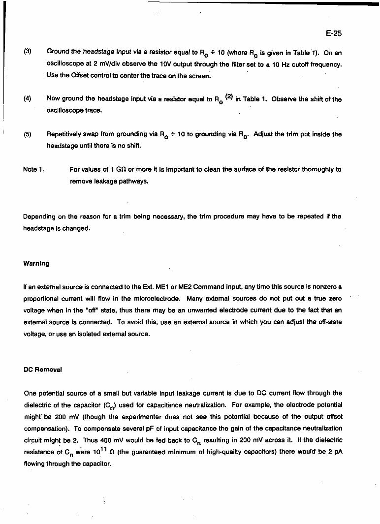
(3) Ground the headstage input via a resistor equal to R^ + 10 (where RQ is given in Table 1). On an
oscilloscope at 2 mV/div observe the 10V output through the filter set to a 10 Hz cutoff frequency.
Use the Offset control to center the trace on the screen.
(4) Now ground the headstage input via a resistor equal to RQ ^ ^ in Table 1. Obsen^e the shift of the
oscilloscope trace.
(5) Repetitively swap fi-om grounding via R^ -}- 10 to grounding via RQ. Adjust the trim pot inside the
headstage until there is no shift.
Note 1. For values of 1 GO or more it is Important to clean the surface of the resistor thoroughly to
remove leakage pathways.
Depending on the reason for a trim being necessary, the trim procedure may have to be repeated if the
headstage is changed.
Warning
If an extemal source is connected to the Ext. MEI or ME2 Command input, any time this source is nonzero a
proportional current will flow in the microelectrode. Many extemal sources do not put out a true zero
voltage when in the "off" state, thus there may be an unwanted electrode current due to the fact that an
extemal source is connected. To avoid this, use an extemal source in which you can adjust the off-state
voltage, or use an isolated extemal source.
DC Removal
One potential source of a small but variable input leakage current is due to DC current flow through the
dielectric of the capacitor (C^) used for capacitiance neutralization. For example, the electrode potential
might t>e 200 mV (though the experimenter does not see this potential because of the output offset
compensation). To compensate several pF of input capacitance the gain of the capacitance neutralization
circuit might be 2. Thus 400 mV would be fed back to C^ resulting in 200 mV across i t If the dielectric
resistance of Op were 10 f l (the guaranteed minimum of high-quality capacitors) there would k>e 2 pA
flowing through the capacitor
E-26
To eliminate this source of leakage current, a DC removal circuit in all HS-2 series headstages removes the
DC voltage from across C^. The DC removal circuit operates with a 1 s or 10 s time constant There may be
a transient shift in the electrode voltage while the Capacitance Neutralization control is being adjusted, but
no net charge is injected into the electrode. The DC voltage is also removed from the shield drive.
Input Resistance
The input resistance of the headstages is predommantly related to RQ. A circuit inside the AXOPROBE-1 A
called a constant current source (CCS) controls the voltage across RQ. Ideally, the voltage across RQ is
independent of the electrode voltage. The accuracy of the CCS in controlling the voltage across RQ is
preset at the factory. Extremely stable components are used in the CCS so that the accuracy will not
deteriorate with time. In general, the CCS is effective to one part in 10 so that the input resistance is
loX-
Other possible factors which would decrease the input resistance are minimized. For example, the field
effect transistor (FET) input of the headstage amplifler is referenced to the input voltage rather than to
ground. This technique is known as bootstrapping. Thus the effective resistance of the input is much
greater than the already high resistance of the FET. Leakage current and resistive loading through the
insulation of the input socket are minimized by using Teflon insulation and by driving the case with the DC
input voltage.
E-27
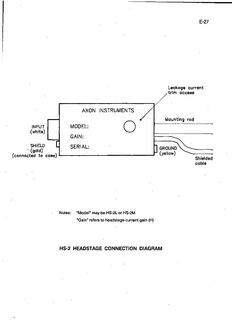
Leakage current
INPUT (white)
SHIELD (gold) A#4 i n f
[
AXON INSTRUMENTS /
MODEL: ( ^
GAIN:
SERIAL:
Mounting rod
^ ^
"1 GROi iNnV^-^ -J (yellow) ^•'~-
Shielded cable
Notes: "Model" may be HS-2L or HS-2M
"Gain" refers to headstage current gain (H)
HS-2 HEADSTAGE CONNECTION DIAGRAM
E-28
HOLDERS
Features
The HL-2 series holders have been designed for low-noise mechanically stable microelectrode recordings
with or without suction. The body of the holders are made out of polycarbonate for lowest noise and easy
cleaning. Maintenance is simple because the holder can be fully disassembled for cleaning and parts
replacement.
Mechanical stability of the electrode is assured several ways. For example, as the electrode cap is closed,
the 'O' ring is forced into a special recess and pulls the electrode firmly tiack into the holder so that its end
presses tightly against the electrode seat The holder mates firmly with the special tefion connectors on the
HS-2, HS-4 and VG-2 series headstages. A 2 mm diameter pin is used for the electrical connection.
The holders are designed to emerge along the long axis of the headstage. A right-angle adapter can be
purchased if it is necessary for the holder to emerge at 90 ' fi-om the headstage. A BNC-to-Axon adaptor
(HLB-2) can be purchased if you wish to use third-pary BNC-style holders.
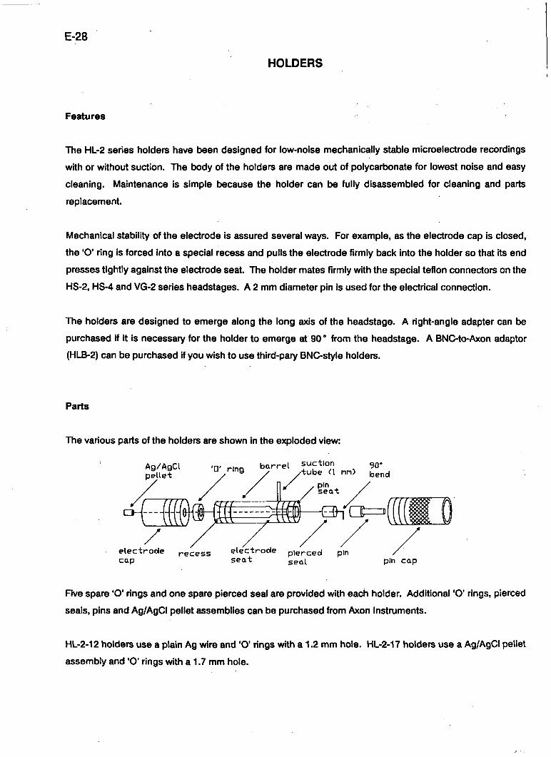
Parts
The various parts of the holders are shown in the exploded view:
Ag/AgCl pelle-t
-•, ^,nq b a r r e l s"^"^ ' " " , 90* u r ing ^ / t ube (\ tnn) bend
OlCl==i
e lec t r ode recess e lec t rode p ierced pin cap sea t sea[ pin cap
Five spare 'O' rings and one spare pierced seal are provided with each holder Additional 'O' rings, pierced
seals, pins and Ag/AgCI pellet assemblies can be purchased from Axon Instruments.
HL-2-12 holders use a plain Ag wire and 'O' rings with a 1.2 mm hole. HL-2-17 holders use a Ag/AgCI pellet
assembly and 'O' rings with a 1.7 mm hole.
E-29
To replace the silver wire, insert the nonchlorided end through the hole of the pierced seal and bend the
last 1 mm over to an angle of 90 °. Press the pierced seal and the wire Into the pin seat. Push the large end
of the pin down onto the t>ent-over wire and into the pin seat. This assures good electrical contact. Screw
the pin cap down firmly but without excessive force.
USE
Insertion of electrode
Make sure the electrode cap is loosened so that pressure on the 'O' ring is relieved, but do not remove the
electrode cap. Push the back end of the electrode through the electrode cap and 'O' ring until it presses
against the electrode seat. Gently tighten the electrode cap so that the electrode is gripped firmly.
To minimize cutting of the 'O' ring by the sharp back end of the electrode, you can smooth the electrode
edges by rotating the back end of the electrode in a bunsen burner flame.
Cleaning
For lowest noise, keep the holder clean. Frequently rinse the holder with distilled water If heavier cleaning
is required, briefly wash In ethanol or mild soapy water Never use methanol or strong solvents.
Filling electrodes
Only the taper and a few millimeters of the shaft of the electrode should t>e filled with solution. The
chlorided tip of the wire should t>e inserted into this solution. Avoid wetting the holder since this will
increase the noise.
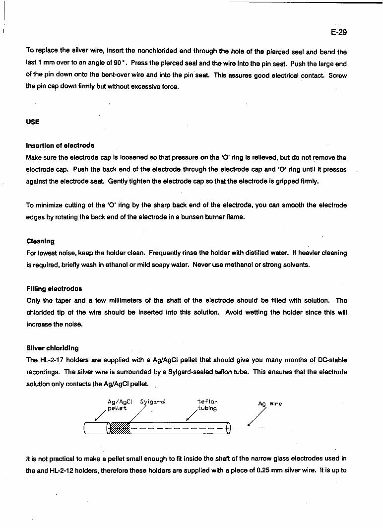
Sihfer chlorlding
The HL-2-17 holders are supplied with a Ag/AgCI pellet that should give you many months of DC-stable
recordings. The silver wire is surrounded by a Sylgard-sealed tefion tube. This ensures that the electrode
solution only contacts the Ag/AgCI pellet
Ag/AgCl , pellet
Sylgard tef lon tubing Ag wire
It is not practical to make a pellet small enough to fit inside the shaft of the narrow glass electrodes used in
the and HL-2-12 holders, therefore these holders are supplied with a piece of 0.25 mm silver wire. It is up to
E-30
you to chloride the end of this wire as required. Chloriding procedures are contained in many
electrophysiology texts (e.g. Purves, 1981). Typically the chlorided wire will need to be replaced every few
weeks.
Heat smoothing the batk end of the electrode extends the life of the chloride coating by minimizing the
amount of scratch damage. Another way to protect the AgCI coating is to slip a perforated teflon tube over
the chlorided region.
The chlorided region should be long enough so that the electrode solution does not come in contact with
the bare silver wire.
Glass Dimensions
Use the HL-2-12 holders for glass fi-om 1.0 to 1.2 mm outside diameter (OD). The optimal dimensions are
1.15 mm OD and >0.5 mm ID.
Use the HL-2-17 holders for glass from 1.5 to 1.7 mm outside diameter (OD). The optimal dimensions are
1.65 mm OD and >1.1 mm ID.
For other glass dimensions you can drill out the bore of the HL-2-12 holder

E-31
IN USE/STANDBY
The In Use/Standby switch is used to put the microelectrode 2 amplifler into a standt)y state when it is not
being used. During Standby: 1) the digital panel meter is tumed off to indicate that ME2 is not in use and
2) the Capacitance Neutralization of ME2 is set to its minimum value. This ensures that the open-circuited
headstage will not oscillate and interfere with the ME1 recording.
E-32
IONOPHORESIS
Either of the electrodes can t>e used for ionophoresis.
Set the retaining current on the DC Current Command control.
Set the ejection current on the Pulse Current Command control. Rememtwr that commands add.
Therefore the ejection current will be smaller than the commanded Pulse current by the amount of the
retaining current. The panel meter and the current outputs will indicate the true currents.
e.g. For retaining current = -5nA
ejection current = 80nA
Set DC Current Command = -5nA
Pulse Current Command = 85nA
Not all of the 30 volt output of the AXOPROBE-1 A is applied to the electrode. Some of it is lost as a voltage
drop across the current-setting and measuring resistor (R^) inside the headstage. Therefore choose a
headstage in which RQ < R^ (the electrode resistance). The H = 1 headstage (with RQ = 10 Mfl) is the best
general choice for ionophoresis. In this case, with a 100 Mfl electrode, passage of 250 nA results in 25 V
being applied to the electrode and 2.5 V being dropped across RQ.
E-33
ION SENSITIVE ELECTRODES - SPECIAL CONSIDERATIONS
Buzz
If the Buzz amplitude and duration are at>ove a certain level some resins will charge up during Buzz and
take several minutes to decay to their normal potential. The maximum allowable amplitudes and durations
must be determined by experiment for each type of resin and electrode.
Capacitance Neutralization
When adjusting the capacitance neutralization a transient change in electrode po^ntial may be seen, it is
due to displacement cun-ent through the capacitance neutralization capacitor There Is no DC change
because the DC removal circuit (see Headstages section) inside the headstage removes the DC voltage
from across the headstage. Even the minute charge which flowed during the transient is ultimately
removed from the electrode.
E-34
MICROELECTRODES FOR FAST SETTLING
MICROELECTRODE CAPACITANCE
To get extremely fast settling it is essential to minimize the transmural capacitance (C ) from the inside of
the microelectrode to the extemal solution. C^ is usually 1-2 pF per mm of immersion. Two applications
requiring different approaches are discussed here.
(1) Target cell near surface of solution.
In an isolated preparation, C^ can be reduced by lowering the surface of the solution as far as possible.
Precautions must be taken to prevent surface tension effects from drawing a thin layer of solution up the
outer wall of the microelectrode. If this film of saline Is allowed to develop, C^ will be much worse that
otherwise. Because the film of saline has axial resistance the contribution to C^ will be very nonlinear, and
the capacitance neutralization circuit will not be able to cope with it. To prevent the saline film from
developing, the electrode should be coated with a hydrophobic material. This can t e done just before use
by dipping the fil led microelectrode into silicone oil or mineral oil. Another method is to coat the electrode
with Sylgard (Hammill et al., 1981).
(2) Target cell deep in solution.
In some preparations, e.g., in vivo CNS, the target cell is several millimeters tielow the surface of the
solution. In this case the more difficult procedure of guarding the electrodes may have to t>e used. This
involves coating the outside of the microelectrode with a metal layer and connecting this layer to the case
socket of the headstage. This procedure does not reduce Cx. Instead, it reduces the effect of C by
controlling the voltage across it. The metal guard layer must be insulated from the preparation solution. For
different approaches to this method see Schwartz & House (1970), Suzuki, Rohlicek & Fromter (1978),
Sachs & McGarrigle (1980) and Finkel & Redman (1983).
Because of the distributed nature of the axial resistance of the microelectrode, of the axial resistance of the
metal layer, and of C , the shielding technique is not perfect. In practice, the effect of these nonidealities is
to cause the step response of the microelectrode to overshoot. To overcome this tendency, the
Capacitance Neutralization circuit has a minimum less than unity.
E-35
MICROELECTRODE RESISTANCE
Another important aspect of themicroelectrode is the tip resistance (RQ). This should be as low as possible
consistent with good impalements of the cell. There are two advantages associated with low values of R.:
(1) Settling time.
The decay time constant for the microelectrode voltage after a current pulse depends strongly on R..
Hence, lower Rg values produce faster settling times. As well, high R^ values are sometimes associated
with a slow final decay even after C has been eliminated.
(2) Stability
R_ of most microelectrodes changes with time and with current passing. R^ is affected not only by the
magnitude of the current but also by its polarity. In general, microelectrodes of low resistance are more
stable during cun-ent passing than microelectrodes of high resistance.
FIUJNG SOLUTIONS
The best filling solution to use depends on the preparation under investigation and the experience of the
investigator Although KCI gives one of the lowest tip resistances for a given tip diameter it is not
necessarily the fastest to settle after a cun-ent pulse. K-cltrate Is sometimes faster
It Is important to be aware that during current passing, large amounts of Ions from inside the microelectrode
can tie ionophoresed into the cell. For example, if current is passed by the fiow of ion species A from the
microelectrode into the cell, then after 50 seconds of current at 1 nA (or 1 second of current at 50 nA) the
change in concentration of A inside a cell 100 M,m in diameter Is 1 mM. If A Is an Impermeant ion, the cell
may swell due to the inflow of water to t alance the osmotic pressure.
RECOMMENDED READING
A small book by Purves (1981) serves as an excellent general reference on microelectrode techniques.

E-36
MODELS
We recommend that you practice using the AXOPROBE-1 A on an RC cell model. The resistor provided with
each headstage can t>e conveniently used to simulate the microelectrode and the RC cell model can t>e
soldered directly to the free end.
E-37
OFFSET
The Offset controls compensate for the junction potentials in the experimental setup.
The offset compensation wori<s by adding a DC voltage to the 10V output. The electrode voltage and
current are not affected.
The compensation range is ±500 mV. The no-compensation point is in the middle of the range of the
multitum dials. Each tum of the dials is approximately 100 mV. The dials can t>e locked after setting.
The normal procedure for using the Offset controls is to zero the output when the microelectrode is outside
the cell. All subsequent readings are then with respect to the potential of the extracellular solution.
E-38
OUTPUT FILTERS
Two filters are provided. These are second-order lowpass filters. Twelve -3 dB fi-equencies (t^) can be
selected.
Order
The "order" of a filter refers to the numtjer of poles (RC sections). Each pole attenuates the high-fi-equency
noise t>y 20 dB/decade (= 6 dB/octave).
Type
An ideal lowpass second-order filter passes all signals at frequencies below f^ with no attenuation, and
attenuates all signals at fi-equencies above f|_ by 40 dB/decade. Practical lowpass filters only approximate
this characteristic. There is a gradual attenuation within the pass band, reaching -3 dB at f|_.
Filters can t)e designed to closely approximzrte the ideal amplitude vs. frequency response (e.g. Butterworth
or Chebyshev) but in this case the step response has considerable overshoot. By allowing a poorer
approximation, the overshoot in the step response can tie made smaller (e.g. < 1% in a Bessel filter) or
eliminated altogether (e.g. multiple coincident pole). The AXOPROBE-1 A filters are of the multiple
coincident pole type. For aficionados this means that Q = 0.5; zeta=1.
Rise Time
Lowpass filters also slow the rise time of the signal. The rise time depends on f^. The 10-90% rise time of
each filter in the AXOPROBE-1 A Is:
t^ « 0.35(fL)"''
where f|_ is in Hz.

E-39
If an external filter is used and it has < 10% overshoot then its t will be within a few percent of the t,. value
just given. Sorhe manufactures specify the -3 dB frequency based on the phase responise of the filter
Instead of its amplitude response. Before using an extemal filter it is advisable to check t,. for a step signal
applied to the input.
When a signal with 10-90% rise time t.| Is passed through a filter with 10-90% rise time t2 the rise time of the
output signal is approximately
tr = J(t^^ * t ^ )
E-40
OUTPUT IMPEDANCE AND PROTECTION
All outputs (except Vg^ j ^ ) are protected by 500 f l output resistors. When loaded by the 1 Mfl input
resistance of typical laboratory recording instruments this output resistance causes 0.05% error
All protected outputs can withstand a continuous short circuit to ground or any voltage in the +15 V range.
However in keeping with normal practice, such short circuits should be avoided.
The V g ^ j ^ output has < 1 f l output impedance so that it can drive the relatively low extemal bath input
impedance of another AXOPROBE. This output can withstand a continuous short circuit to ground but not
to+15V.
E-41
PANEL METERS
Voltage
One meter can display V.| or V.|-V2. The second displays V2. The displays are in mV. These unity-gain
voltages are derived from the x10 outputs. Thus they include the correction potentials (Resistance
Compensation, Offset, Bath Potential, Calibration).
Since the x l 0 outputs saturate at atjout ±13 V, the digital displays saturate at atxiut ±1300 mV.
Current
The third meter displays l.| or I2. The required current is selected on the Display switch.
The decimal point is automatically placed to correspond to the current gain (H) of the headstage in use. For
H = x l , xO.1, xO.01 the display is in nA. For H = xO.0001 the display is in pA For H = x l 0 or more the display
is in ^A.
The current meter is placed directly above the thumbwheel switch of the Step Command generator When
setting this switch one can avoid the mental effort of scaling by H by taking the decimal point position
directly from the current meter
Round-Off Error and Zero Error
Digital meters are often out by one unit In the least significant (right-most) digit. This is because the reading
is rounded off to the closest value.
The current meter may indicate 001 even when no current is commanded. It is most likely that this is a zero
error in the current measurement circuit and meter, and not due to input leakage current.
E-42
POWER-SUPPLY GLITCHES
The AXOPROBE-1 A has been designed to minimize the effects of power-supply transients (glitches). This is
achieved by 1) taking the incoming power through a radio frequency interference (RFI) filter, and 2)
capacitlvely isolating the transformer primaries and secondaries.
Nevertheless, some power-supply glitches do get through. These can cause transients to appear on the
voltage and current outputs which may corrupt high-gain recordings (for example, during noise analysis).
The only completely effective way to gain immunity from mains glitches is to eliminate them at their source.
Most glitches are due to the switching on and off of other equipment and lights on the same power-supply
circuit. Precautions to be taken include:
(1) Avoid switching equipment and lights on or off while recordings are tieing made.
(2) Water t)aths, heaters, coolers etc. should operate from zero-crossing relays.
(3) RFI filters should be installed in glitch-producing equipment
In most circumstances occasional transients on the outputs are inconsequential and therefore no
precautions will have to t)e taken.
E-43
POWER SUPPLY VOLTAGE SELECTION & FUSE CHANGING
Supply Voltage
The AXOPROBE-1 A can wori< from all international supply voltages. The two Input ranges are:
(1) 115V: For 100 Vac to 125 Vac operation.
(2) 230 V: For 200 Vac to 250 Vac operation.
To change the supply voltage setting:
(1) Disconnect the power cord
(2) Remove the top cover
(3) Locate the slide switch lat>eled "S2" at the back of the power supply board. The power supply board
is the small horizontal board in the left side of the instrument.
(4) For 115 V operation slide S2 to the left towards the label "115".
For 230 V operation slide S2 to the right towards the lat>el "230".
(5) Replace the top cover
(6) Re-connect the power cord.
(7) Mart< the new operating voltage on the identification plate on the rear of the Instrument.
Changing the Fuse
The AXOPROBE-1 A uses a 0.5 A 250 V slow-acting 5 x 20 mm fuse on both voltage ranges. Before
changing the fuse investigate the reason for its failure.
E-44
To change the fuse:
(1) Disconnect the power cord.
(2) Use a screwdriver or something similar to lever out the fuse holder
(3) Discard the fuse from the active slot. I.e. the slot which places the fuse closest to the inside of the
instrument.
(4) Shift the spare fuse from the spare slot (i.e. the slot which places the fuse towards the outside of the
instrument) to the active slot.
(5) Re-connect the power cord.
E-45
RESISTANCE COMPENSATION
Description
Associated with the current flow (I) in a microelectrode is a voKage drop across the microelectrode which
depends on the microelectrode resistance (R^). This unwanted IR voltage drop adds to the recorded
potential. The Resistance Compensation control can be used to balance out this voftage drop so that only
membrane potential is recorded. The particular setting required to achieve t)alance is a measure of the
microelectrode resistance. On eariier amplifiers the Resistance Compensation control was named "Bridge".
Suggested Use
Set the Destination switch to ME1/2 and externally trigger the Step Command generator so that pulses of
current are repetitively injected into ME1/2. Start with the Resistance Compensation control set to zero.
Advance the dial until the fast voltage steps seen at the start and finish of the current step are just
eliminated. The residual transient at the start and finish of the current step is due to the finite response time
of the microelectrode. No attempt is made to remove this transient tiecause 1) it only covers a very brief
period, 2) it is a useful Indication of the response time of the microelectrode, and 3) no valid information
can be recorded in this period even if the transient is artificially removed. The transient can be minimized
by correctly setting the Capacitance Neutralization.
The balancing procedure Is Illustrated in the following figure. The trace in A was recorded in a model cell
when the Resistance Compensation control was correctly set. In response to a positive current pulse the
membrane potential t>egan to charge up. Before the membrane potential reached its final value the current
pulse was terminated and the membrane potential exponentially decayed to its final value.
The traces in B were recorded at a sweep speed which was fast compared with the membrane time
constant, hence the membrane responses look like straight lines. The top trace shows the voltage
recorded when no Resistance Compensation was used. The response was dominated by the IR voltage
drop across the electrode. In the middle trace the Resistance Compensation was optimum and in the
bottom trace it was slightly overused.
When the Resistance Compensation is optimum the resistance of the microelectrode can be read directly
fix>m the dial. The sensitivity is 10 - H Mfl per tum.
E-46
The Resistance Compensation controls operate on the 10V outputs. The controls saturate when the IR
voltage drop exceeds ±1200 mV referred to the input.
Intracellular Balancing
The traces in the figure were all recorded with the electrode inside the cell. Since the electrode response
and the oscilloscope sweep speed were fast compared with the membrane time constant (as in Figure part
B), the correct Resistance Compensation setting was easy to see, even through the electrode was inside
the cell.
It is sometimes useful to inject a t}rief small current pulse at the start of each oscilloscope sweep in order to
continually check the Resistance Compensation setting during the course of an experiment
FIGURE:
Illustration of Resistance Compensation techniques. All traces were recorded from the lOV. output. The
model cell was 10 Mfl//1 nF. R^ was 10 Mfl. Recording t)andwidth: 30 kHz. Vertical calibration: 20 mV
refenBd to V.|.
A Response to - 5 nA 10 ms current pulse. Compensation optimum. Trace is membrane response only.
Cal. bar 20 ms.
B. Response to -t-S nA 1 ms pulse. Cal. bar 1 ms.
Top trace: No compensation. Fast voltage steps at start and finish of the current pulse are the electrode IR
voltage drop.
Middle trace: Compensation optirhum. Trace is membrane response only. Transient electrode response
remains.
Bottom trace: Too much compensation. Negative going step is Introduced by the compensation circuit.
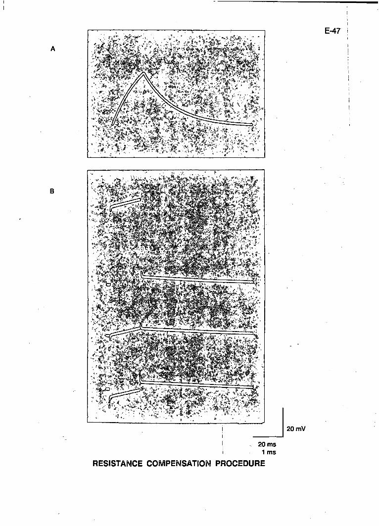
' i ' -"^ %"J«.f,:^;
E-47
B
20 mV
RESISTANCE COMPENSATION PROCEDURE
E-48
TEN-TURN POTENTIOMETERS
The ten-tum potentiometers used in the AXOPROBE-1 A are high-quality wirewound types.
An inherent protilem of wirewound potentiometers Is that the wire elements tend to oxidize. This condition
is easily cured.
If a potentiometer t)ecomes noisy, the potentiometer manufacturer recommends rapidly spinning the knob
20-30 times (between full clockwise and full counterclockwise. This clears the pxide off the element and
restores noise-free operation.
E-49
TEST CURRENT
The Test Current switch injects a constant current Into the microelectrode so that the microelectrode
resistance can t}e measured. Test Current can t>e used two ways.
1) To read resistance on the digital panel meter Set the Resistance Compensation control to read
zero. Press the Test switch. The electrode resistance corresponds to the shift in the electrode
potential. Depending on which way the Test switch is pushed the shift is either H mV/Mfl or 100H
mV/Mfl (used for increased sensitivity). The current passed is either H or 100H nA respectively.
2) To read resistances by setting the Resistance Compensation control: Press the Test switch. Tum
the Resistance Compensation control to eliminate the shift in electrode potential. Read the
electrode resistance on the Resistance Compensation Dial.
Cell Resistance
The Test Current switch injects a DC current. If the electrode is intracellular the resistance measured will be
the sum of the electrode resistance and the membrane resistance.
E-50
TROUBLE SHOOTING
it has t>een our experience at Axon Instruments that the majority of troubles reported to us have been
caused by faulty equipment connected to our instruments.
If you have a pix)blem, please disconnect all instruments connected to the AXOPROBE-1 A except for the
oscilloscope and one headstage. Ground the headstage through the original test resistor supplied by Axon
Instruments. If the problem persists, please call us for assistance.
E-51
REFERENCES
Finkel, A S. & Redman S. J. (1983). A shielded microelectrode suitable for single-electrode voltage
clamping of neurones In the CNS. J. Neurosci. Meths. 9,23-29.
Hamilt, O.P., Marty, A , Sakmann, B. & SIgworth, F. J. (1961). Improved patch-clamp techniques for high-
resolution cun-ent recording from cells and cell-free membranes patches. Pfigers Arch. 391,85-100.
Purves, R.D. (1981). Microelectrode Methods for Intracellular Recording and lonophoresis. London:
Academic Press.
Sachs, F. & McGarrigle, R. (1980). An almost completely shielded microelectrode. J. Neurosci. Meths. 3,
151-157.
Schwartz, T. I & House, Randall C. (1970). A small-tipped microelectrode designed to minimize capactive
artifacts during the passage of current through the t)ath. Rev. ScL Inst 41,515-517.
Suzuki, IC, Rohlicek, V. & Fnnter, E. (1978). A quasi-totally shielded, loviM;apac'itance glass-
microelectrode with suitable amplifiers for high-frequency intracellular potential and impedance
measurements. F*flgers Arch. 378,141-148.
F-1
WARRANTY
We warrant every AXOPROBE-1 A and every headstage to be free from defects in material and workmanship under normal use and service. For 12 months from the date of receipt we will repair or replace without cost to the customer any of these products that are defective and which are returned to our factory properly packaged with transportation charges prepaid. We will pay for the return of the product to the customer if the shipment is to a location within the United States. If the shipment is to a location outside the United States the customer will be responsible for paying all shipping charges, duties and taxes.
Before returning products to our factory the customer must contact us to obtain a Return IVIerchandise Authorization number (RMA) and shipping instructions. Failure to do so will cause long delays and additional expense to customer. Complete a copy of the RMA form on the next page and return it with the product.
This warranty shall not apply to damage resulting from improper use, improper care, improper modification, connection to incompatible equipment, or to products which have been modified or integrated with other equipment in such a way as to increase the time or difficulty of servicing the product.
«
This warranty is in lieu of all other warranties, expressed or implied.
Axon Instruments, Inc.
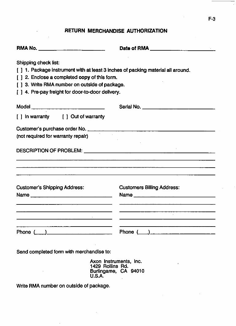
F-3
RETURN MERCHANDISE AUTHORIZATION
RMA No. Date of RMA
Shipping check list: [ ] 1. Package instrument with at least 3 Inches of packing material all around. [ ] 2. Enclose a completed copy of this form. [ ] 3. Write RMA number on outside of package. [ ] 4. Pre-pay freight for door-to-door delivery.
Model
[ ] In warranty [ ] Out of warranty
Customer's purchase order No. (not required for warranty repair)
Serial No.
DESCRIPTION OF PROBLEM:
Customer's Shipping Address: Name
Customers Billing Address: Name
Phone ( ). Phone ( ).
Send completed form with merchandise to:
Axon Instruments, Inc. 1429 Rollins Rd. Burlingame, CA 94010 U.S.A.
Write RMA number on outside of package.

F-4
F-5
POLICY STATEMENT
The aim of Axon Instruments, Inc. Is to manufacture electronic instruments for use in research and data acquisition. Emphasis is placed on instrumentation which satisfies specialized and sophisticated requirements to the highest standards of technical excellence. In ail cases of conflict, achievement of excellence is held to be more important than containment of costs.
SERVICE
Service will be done at the factory. The usual time till dispatch of a repaired unit is 5-10 days after receipt.
Before returning products to the factory customers must obtain a Return Merchandise Authorization number (RMA) and shipping instructions. Failure to do so will cause long delays and additional expense to customer.

F-6
F-7
COMMENT FORM
Please use a copy of this form to submit comments about the AXOPROBE-1 A, the headstages or the manuals. We will consider your comments carefully and endeavor to make any improvements suggested. You do not have to complete every section.
Features I like:
Features I don't like:
Features I would like to see added:
General:
Name Address.
Phone ( ).


![[tel-00861119, v1] Implantable microelectrode biosensors for - HAL](https://img.pdfslide.net/doc/110x75/620615a58c2f7b17300473ad/tel-00861119-v1-implantable-microelectrode-biosensors-for-hal.jpg)