Embed Size (px)
Citation preview
Service Manual
COBRIX3 & COBRIX3 multibev On-line Beverage Analyzer


Service Manual
COBRIX3 & COBRIX3 multibev On-line Beverage Analyzer

While every precaution has been taken in the preparation of this document, Anton Paar GmbH assumes no responsibility for technical or printing errors or omissions.
Nor is any liability assumed for damages resulting from the use of the information contained in this instruction manual.
Anton Paar GmbH does not make a commitment to update the information in this manual. Specifications are subject to change without notice.
All rights reserved (including translation). No part of this document may be translated, reproduced or distributed in any form (print, photocopy, microfilm or any other process) without the prior written permission of Anton Paar GmbH.
Trade marks may be used in this instruction manual without being marked as such. These are the property of their respective owners and are legally protected.
Published by Anton Paar GmbH. Printed in Austria.
Copyright © 2004 Anton Paar GmbH, Graz, Austria
Contact: Anton Paar GmbHAnton-Paar-Str. 20A-8054 Graz / Austria - EuropeTel: +43 316 257-0Fax: +43 316 257-257
E-mail: [email protected]: www.anton-paar.com
Date: 31.12.2004
Document number: B43IB20C.fm
Contents
1 System Overview ............................................................................................................................. 71.1 Versions of COBRIX3.............................................................................................................. 71.2 Functional Components/Spare Part List .................................................................................. 8
2 Safety Instructions......................................................................................................................... 173 Symbols in the Service Manual .................................................................................................... 194 Reference Manuals ........................................................................................................................ 215 Service and Maintenance.............................................................................................................. 236 Cleaning the COBRIX3 .................................................................................................................. 257 Disconnecting the COBRIX3......................................................................................................... 27
7.1 Stopping the COBRIX3.......................................................................................................... 277.2 Disconnecting the Power Supply ........................................................................................... 277.3 Disconnecting the Compressed Air Supply ........................................................................... 287.4 Closing the Bypass Valve...................................................................................................... 287.5 Disconnecting the COBRIX3 from the Product Line .............................................................. 297.6 Removing the Stainless Steel Covers ................................................................................... 297.7 Opening the Stainless Steel Housing Rear Door................................................................... 29
8 Checking the Pump Motor Overload Relay ................................................................................. 319 Relay for the Liquid Sensor .......................................................................................................... 3510 24V Switched Mode Power Supply............................................................................................... 3911 Line Protector................................................................................................................................. 4112 Additional Alarm Relay.................................................................................................................. 4313 Alarm/Warning Light...................................................................................................................... 4714 LED Display.................................................................................................................................... 4915 Replacing the CARBO 2100 CO2 Transducer ............................................................................. 5316 Replacing the DPRn or DSRn Transducer................................................................................... 5717 Replacing the Shaft Seal of the Pump ......................................................................................... 6118 Replacing the Pump ...................................................................................................................... 6719 Disconnecting the Pump Cable .................................................................................................... 6920 Wetted Parts................................................................................................................................... 7521 List of Spare Parts for 1 Year of Operation ................................................................................. 7722 List of Tools.................................................................................................................................... 7923 Troubleshooting............................................................................................................................. 8124 Document Numbers....................................................................................................................... 83Appendix A: Service/Maintenance Report .................................................................................... 84Appendix B: Feedback Form.......................................................................................................... 90
B43IB20 5

6 B43IB20

1 System Overview
1 System Overview
1.1 Versions of COBRIX3
There are 2 versions of the COBRIX3:
COBRIX3 multibev Beverage Analyzer:
All-round version with DSRn for
• sugared and diet beverages• sugared beverages with sugar inversion compensation• beverages with alcohol (alcoholic lemonades, malternatives, etc.)• beer• wine
COBRIX3 Beverage Analyzer:
Basic version with DPRn for sugared and diet beverages.
B43IB20 7

1 System Overview
1.2 Functional Components/Spare Part List
Fig. 1.1 - 1 Side view of COBRIX3
Alarm lamp Warning lamp
Main switch
Switch box includingmPDS evaluation unit
Bypass with liquid
Productionline
Stainless steel (SS)protection cover
Front door
CO2 transducerCARBO 2100
DPRn or DSRndensity/sound velocitytransducer (see warning 3
sensor and valves
Rear door
Lock (see warning 1 below)
Pump (seewarning 2below)
below)
(see warning 4below)
Handles (see warning 5 below)
8 B43IB20

1 System Overview
Warning1:High voltage. Danger of electric shock. Before removing outside covers, switch off the instrument and disconnect it from the mains.Service procedures may only be carried out by authorized and fully trained service personnel.
Warning 2:The pump may be under pressure. Before opening the pump, disconnect the pump from the product line and exhaust it.Service procedures may only be carried out by authorized and fully trained service personnel.
Warning 3:The product line may be under pressure. Before opening the DPRn or DSRn, disconnect it from the product line.Service procedures may only be carried out by authorized and fully trained service personnel.
Warning 4:The product line may be under pressure. Before opening the CARBO 2100, disconnect it from the product line.Service procedures may only be carried out by authorized and fully trained service personnel.
Warning 5:To remove the cover, use the handles. Do not use the handles for carrying the COBRIX3.
Warning 6:• Hot product or hot CIP liquid may come out of the sample valve.• Wear protective gloves to open and clsoe the sample valve.• Take care not to get in touch with the hot rinsing liquid or hot product.
B43IB20 9

1 System Overview
Alarm lamp
Measuring value
Optional displays for Brix / %Diet,CO2 and alcohol or temperature
Warning lamp
Pump start
storage buttonAlarm Reset Button
button
Main switch
Optional productselector switch
Pump ON/OFFswitch
Fig. 1.1 - 2 Operator Interface of COBRIX3
10 B43IB20

1 System Overview
Fig. 1.1 - 3 Parts of COBRIX3
B43IB20 11

7045
12864 11040 11039
Fig. 1.1 - 4 Options for COBRIX3
Bottle counter
Flow monitor Product selector switch
3 LED Displays
12 B43IB20

1 System Overview
COBRIX3 MultiBev beverage analyzer with Density-Sound Transducer:
10765 COBRIX3 MULTIBEV BEVERAGE ANALYZER 115V WITH DSRn
10764 COBRIX3 MULTIBEV BEVERAGE ANALYZER 230V WITH DSRn
Consists of:
DSRn 427 density/sound velocity transducer
CARBO 2100 CO2 transducer
mPDS 2000 V3
By-pass Product Pump
Liquid Sensor
COBRIX3 beverage analyzer with Density Transducer:
10763 COBRIX3 BEVERAGE ANALYZER 115V WITH DPRn
10762 COBRIX3 BEVERAGE ANALYZER 230V WITH DPRn
Consists of:
DPRn 427 density transducer
CARBO 2100 CO2 transducer
mPDS 2000 V3
By-pass Product Pump
Liquid Sensor
Option:
75504 DAVIS DATA ACQUISITION SOFTWARE
7045 BOTTLE COUNTER
12864 FLOW MONITOR COBRIX3
11039 3 LED DISPLAYS COBRIX3 MOUNTED
11040 EXTERNAL PRODUCT SELECTOR SWITCH COBRIX3
12865 MOUNTING SET SAWA PUMP COBRIX3
Accessories:
1151 ELBOW TUBE 45° DN 25 TRICLAMP
B43IB20 13
1 System Overview
77390 ELBOW TUBE 90° DN 25 TRICLAMP
5107 TRI-CLAMP FILTER DN25 EPDM
12995 CONVERTER KIT PC RS232-RS485
Spare parts for "Speck pump NPY 2051":
77385 CENTRIFUGAL PUMP NPY-2051 115V 50/60HZ
77506 CENTRIFUGAL PUMP NPY-2051 230V 50/60HZ
77953 SHAFT SEAL FOR NPY-2051O-RING FOR NPY-2051 CASE77954
77957 IMPELLER NPY-2051 50/60 Hz
77507 WASHER G3/4" PCTFE
Spare parts for "Sawa Pump":
8428 CENTRIFUGAL PUMP SAWA 230V 50HZ
8429 CENTRIFUGAL PUMP SAWA 115V 60HZ
9404 SHAFT SEAL SLIP RING SAWA PUMP
9405 SHAFT SEAL LIP RING SAWA PUMP
8433 TRICLAMP WASHER SMALL 25MM EPDM
8432 TRICLAMP BRACKET DA 25mm 1.4301
10394 FLEXIBLE HOSE COBRIX3 SAWA PUMP-DPR DN10X260
8424 FLEXIBLE HOSE COBRIX3 MAIN LINE-SAWA PUMP DN12X800
Spare parts for COBRIX3 - bypass etc.:
70768 CLAMP 25mm DIN 32676 1.4301
70769 WASHER 25MM DIN 32676 EPDM
10767 LIQUID SENSOR RELAY 115V
10766 LIQUID SENSOR RELAY 230V
10790 LIQUID SENSOR COBRIX3
77514 WASHER G3/8" PCTFE
1910 BUTTERFLY VALVE DN25 CLAMP / WELDING END
10393 FLEXIBLE HOSE COBRIX3 MAIN LINE-SPECK PUMP DN12X830
4254 FLEXIBLE HOSE PUMP/DPR 3/4" DN10 3/8" 400 MM
10396 FLEXIBLE HOSE COBRIX3 CARBO-MAIN LINE DN10X1500
14 B43IB20

1 System Overview
10775 SAMPLE VALVE COBRIX3 TRICLAMP DN10
10395 FLEXIBLE HOSE COBRIX3 DPR-CARBO DN10X395
B43IB20 15

16 B43IB20

2 Safety Instructions
2 Safety Instructions
• This service manual does not claim to address all of the safety issues associated with the service and operation of the COBRIX3 and samples. It is the service technician’s responsibility to ensure all health and safety regulations are met for the persons concerned prior to starting service and maintenance work.
• Before servicing the COBRIX3, read this manual completely.
• Anton Paar GmbH only warrants the proper functioning of the COBRIX3 if no unauthorized adjustments have been made to mechanical parts, electronic parts and software, and the following points are adhered to.
• Follow all hints, warnings and instructions in the manual to ensure the correct and safe functioning of the COBRIX3.
• Do not handle the COBRIX3 other than described in the manual. Anton Paar GmbH is not liable for damages caused by incorrect handling of the COBRIX3.
• The installation procedure must only be carried out by authorized personnel who are familiar with the installation instructions.
• Do not operate the COBRIX3 if a malfunction is suspected, or damages, injuries or loss of life cannot be excluded under all circumstances.
• The COBRIX3 is not an explosion-proof instrument and therefore must not be operated in areas where there is a risk of explosion.
• Use only original spare parts and parts explicitly indicated as parts for repair.
• Service or repair work must only be carried out by qualified personnel, authorized service centers, professional workshops or by Anton Paar GmbH.
• Use only recommended and appropriate tools.
• Ensure that all operators are fully trained to use the COBRIX3 correctly and safely.
• Due to the nature of the measurement, the measuring results do not only depend on the correct use and functioning of the COBRIX3, but may also be influenced by other factors. We therefore advise that the analysis results are plausibility tested before consequential actions are taken.
• Repair and service procedures may only be carried out by authorized personnel or by Anton Paar GmbH.
B43IB20 17

• If the safety appliances of the COBRIX3 are opened, changed or interrupted during the service, a safety check must be performed after the repair.
• Never install the COBRIX3 Beverage Analyzer and the evaluation unit in areas where strong electromagnetic fields are present.
• Before carrying out any service procedures, the COBRIX3 Beverage Analyzer must be disconnected from the mains, product line and compressed air supply.
• The COBRIX3 Beverage Analyzer contains electrostatically sensitive devices. When handling modules/components of the instrument they must be protected from electrostatic discharge. Use a grounded wristband when handling these components. If you return modules for repair, use appropriate packaging which protects these modules from electrostatic discharge.
Do not touch areas marked with this symbol (yellow) when the power is turned on. This "Warning" sign on the instrument means "Carefully read the accompanying documents".
18 B43IB20

3 Symbols in the Service Manual
3 Symbols in the Service Manual
The following symbols are used in the instruction manual:
Warning:The "Warning" sign indicates a hazard. It calls attention to an operating procedure, practice, etc. which, if not correctly performed or adhered to, could result in injury or loss of life. Do not proceed beyond a "Warning" sign until the indicated conditions are fully understood and met.
Important:The "Important" sign indicates a hazard. It calls attention to an operating procedure, practice, etc. which, if not correctly performed or adhered to, could result in damage or destruction of the instrument or parts of it. Do not proceed beyond an "Important" sign until the indicated conditions are fully understood and met.
Hint:The "Hint" sign calls attention to any additional information which might be of use to the operator.
B43IB20 19

20 B43IB20

4 Reference Manuals
4 Reference Manuals
The standard COBRIX3 on-line beverage analyzer consists of:
• the mPDS 2000V3 evaluation unit
• the DPRn density transducer or DSRn density/sound velocity transducer (multibev)
• the CARBO 2100 CO2 transducer
For detailed information concerning these instruments please refer to the following manuals.
• mPDS 2000V3 Instruction Manual
• mPDS 2000V3 Program Description Beverages
• mPDS 2000V3 Service Manual
• CARBO 2100 CO2 transducer Instruction Manual
• CARBO 2100 CO2 transducer Service Manual
• DPRn density transducer Instruction Manual
• DSRn density & sound velocity transducer Instruction Manual
B43IB20 21

22 B43IB20

5 Service and Maintenance
5 Service and Maintenance
To ensure reliable and trouble-free operation, the COBRIX3 must be checked, serviced and cleaned periodically.
The COBRIX3 service and maintenance intervals depend on the operating conditions. The following is recommended as a general maintenance procedure.
Daily
• Check daily for error messages on the display of the evaluation unit.
Once a week
• Check the inside of the stainless steel cover (SS cover) once a week for leaks.
• Check (visually) the condensate level in the pressure regulator.
• Check the set pressure of the pressure regulator. The set pressure must be 4.5 bar.
• Process instruments are often exposed to extreme working conditions such as pressure shock, sudden changes in temperature, aggressive samples, etc. which may cause drifts or failure. Therefore, it is essential to periodically compare the measured results to reference values and readjust the measuring system if required.
• Check the indicated concentration of the product.• Check the indicated CO2 concentration.• Check the indicated temperature of the product• Check the indicated line pressure.
Pump maintenance:
The maintenance interval depends on the process and operating conditions of the pump. We recommend checking the following:
- Sample residues on the pump and motor→ Clean the pump and motor
Although the pump and motor are protected by stainless steel covers, product or rinsing liquid may get under the cover e.g. through the opening
B43IB20 23

5 Service and Maintenance
on the bottom. Remove product residues from the pump and motor using warm water. This prevents the motor becoming blocked and ensures proper cooling of the motor.
- Leakage at the COBRIX3 hoses→ Tighten all fittings
We use high quality seal rings for all fittings of the COBRIX3. Immediately after start up some leakage may occur due to the initial compression of the seal rings.
- Leakage at the shaft seal→ Replace the shaft seal
During normal operation there should be no leakage at the shaft seal. Foreign substances or wear can damage the shaft seal causing leakage. In this case, the shaft seal must be replaced. Continuous leakage at the shaft seal may destroy the motor of the pump.
Every 6 month
• Replace the diaphragms: The diaphragms of the CARBO 2100 are mechanically stressed and will wear out. They should be replaced after a period of 4 months up to half a year. The period depends on the operating conditions.
• Check the CARBO 2100 impeller visually and replace it if necessary.
• Check the drives of the diaphragm valves visually and replace if necessary.
For more detailed service and maintenance information concerning the CARBO 2100 CO2 transducer, mPDS 2000V3 evaluation unit and DPRn or DSRn transducer, please refer to the respective manual:
• CARBO 2100 CO2 transducer service manual.
• mPDS 2000V3 service manual.
• DPRn density transducer instruction manual or DSRn density & sound velocity transducer instruction manual.
24 B43IB20

6 Cleaning the COBRIX3
6 Cleaning the COBRIX3
The COBRIX3 cleaning interval depends on the operating conditions. We recommend cleaning the COBRIX3 at least once a week.
• Check if any sample is visible on the instrument and clean if necessary.
• Use water or warm water as the cleaning agent.
Warning:• See chapter 7: Disconnecting the COBRIX3.• See chapter 7.1: Stopping the COBRIX3.• See chapter 7.2: Disconnecting the Power Supply.• See chapter 7.4: Closing the Bypass Valve.• See chapter 7.6: Removing the Stainless Steel Covers.
B43IB20 25

26 B43IB20

7 Disconnecting the COBRIX3
7 Disconnecting the COBRIX3
7.1 Stopping the COBRIX3
Before carrying out any service procedures, it is necessary to STOP the COBRIX3. Perform the following steps:
• Inform the production manager that the COBRIX3 will be stopped
• Turn off the power for the rotary pump using the Pump ON/OFF switch (see Fig. 1.2).
• Turn off the main switch (see Fig. 1.2)
7.2 Disconnecting the Power Supply
1. Turn off the main switch
The lower part of the COBRIX3 contains the transducers. For service or maintenance work on the lower part of the COBRIX3, turn off the main switch of the COBRIX3 (see Fig. 1.2)
2. Turn off the circuit breaker
Turn off the main switch. The upper part of the COBRIX3 contains the evaluation unit and the electrical equipment. For service or maintenance work on the upper part of the COBRIX3, the circuit breaker must be turned off. The circuit breaker is located in a switch cabinet outside the COBRIX3. Please contact the plant electrician.
Warning:Before carrying out any service procedures, the COBRIX3 Beverage Analyzer must be disconnected from the mains, product line and compressed air supply.
B43IB20 27

7 Disconnecting the COBRIX3
7.3 Disconnecting the Compressed Air Supply
Disconnect the compressed air hose from the inlet at the pressure regulator of the CARBO 2100 transducer.
7.4 Closing the Bypass Valve
• Close the bypass valves to separate the COBRIX3 from the product line (see Fig. 1.1-3).
• Open the sample valve to relieve the pressure in the bypass (see Fig. 1.1-3).
Warning:• Only fully trained and authorized technicians may carry out this
procedure.• The COBRIX3 is supplied with line voltage which may be life-threatening if
handled improperly.• Make sure that the line voltage is turned off when handling the power
cable.
Warning:• Compressed air can be hazardous.• Turn off the compressed air supply before disconnecting the hose!
Fig. 7.3-1 Pressure regulator
28 B43IB20

7 Disconnecting the COBRIX3
For service or maintenance for the transducers, first separate them from the product line.
7.5 Disconnecting the COBRIX3 from the Product Line
For a safe separation of the COBRIX3 from the product line, we recommend disconnecting the bypass from the product line completely.
7.6 Removing the Stainless Steel Covers
Tools:
Allen screwdriver 3mm
Remove the stainless steel (SS) covers for service or maintenance work on the lower part of the COBRIX3.
• Open the screws of the SS protection covers.
• Use the handles to remove the SS protection covers (see Fig. 1.1-3).
7.7 Opening the Stainless Steel Housing Rear Door
Tools:
Key for the lock of the electronic housing
For service or maintenance procedures on the electronics it is necessary to open the SS housing rear door.
• Open the lock of the rear door (see Fig. 1.1-1).
• After shipment the key for the lock is located behind the front door (see Fig. 7.7-1).
W
Warning:• The product line may be under pressure.• Close the bypass valves.• Open the sample valve to relieve the pressure.• Disconnect the bypass from the product line by opening the Triclamp at
the bypass hoses (see Fig.1.1-3).
B43IB20 29

7 Disconnecting the COBRIX3
Warning:High voltage. Danger of electric shock. Before opening the rear door, switch off the main switch and the circuit breaker. Service procedures may only be carried out by authorized and fully trained service personnel.
Fig. 7.7 - 1 Key for rear door
30 B43IB20

8 Checking the Pump Motor Overload Relay
8 Checking the Pump Motor Overload Relay
Tools:
Key for the lock of the housing rear door (see chapter 7.7).
W
Warning:• See chapter 7: Disconnecting the COBRIX3.• See chapter 7.1: Stopping the COBRIX3.• See chapter 7.2: Disconnecting the Power Supply.• See chapter 7.7: Opening the Stainless Steel Housing Rear Door.
Fig. 8 - 1
B43IB20 31

A The trip current must be adjusted to the rated current of the pump motor
Typical values are mentioned in the following table:
B Push to test the overload relay
CBA D
Fig. 8 - 2
Warning:The rated current of the pump must be taken from the label directly on the pump. A wrong setting can destroy the pump in case of a malfunction.
Type of pump (cat. No, voltage, ...) Typical current
77506,230 VAC, SPECK NPY 2051 2,5 A
77385, 115 VAC,SPECK NPY 2051 3,8 A
8428, 230 VAC, SAWA 1,8 A
8429, 115 VAC, SAWA 4,35 A
32 B43IB20

8 Checking the Pump Motor Overload Relay
C Trip indicator window: If the yellow indicator is visible, the overload relay has tripped.
D “Man” mode of operation is selected. Push to reset the relay.
B43IB20 33

34 B43IB20

9 Relay for the Liquid Sensor
9 Relay for the Liquid Sensor
Spare parts:
10766 LIQUID SENSOR RELAY 230V10767 LIQUID SENSOR RELAY 115V
Tools:
Key for the lock of the housing rear door (see chapter 7.7).
Slotted screwdriver 3mm
A The resistance value is set to 20 kOhm.
Warning:• See chapter 7: Disconnecting the COBRIX3.• See chapter 7.1: Stopping the COBRIX3.• See chapter 7.2: Disconnecting the Power Supply.• See chapter 7.7: Opening the Stainless Steel Housing Rear Door.
Fig. 9 - 1
A
B43IB20 35
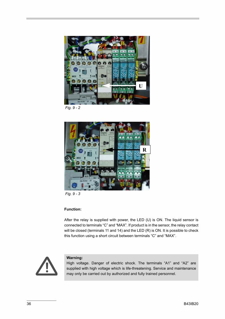
Function:
After the relay is supplied with power, the LED (U) is ON. The liquid sensor is connected to terminals “C” and “MAX”. If product is in the sensor, the relay contact will be closed (terminals 11 and 14) and the LED (R) is ON. It is possible to check this function using a short circuit between terminals “C” and “MAX”.
Fig. 9 - 2
U
Fig. 9 - 3
R
Warning:High voltage. Danger of electric shock. The terminals “A1” and “A2” are supplied with high voltage which is life-threatening. Service and maintenance may only be carried out by authorized and fully trained personnel.
36 B43IB20

9 Relay for the Liquid Sensor
Replacement:
• See chapter 7.2: Disconnecting the Power Supply.
• Reconnect the cables to the correct terminals.
• The cable ties are used to make a safe separation between circuits with high and SELV voltage. Therefore, the cable ties must not be changed.
• Mount the plastic screw to terminal 12 of the new relay.
B43IB20 37

38 B43IB20

10 24V Switched Mode Power Supply
10 24V Switched Mode Power Supply
Spare parts:
10782 POWER SUPPLY 85-264VAC 24VDC 2,1A
Tools:
Key for the lock of the housing rear door (see chapter 7.7).
A The switched mode power supply has a rated power of 50W. It is the power supply for the:
- CARBO 2100 … 15W- Alarm and Warning Lamps … 20W- COBRIX3 Electronics … 10 W- mPDS2000V3 24V circuits … 5W
Warning:• See chapter 7: Disconnecting the COBRIX3.• See chapter 7.1: Stopping the COBRIX3.• See chapter 7.2: Disconnecting the Power Supply.• See chapter 7.7: Opening the Stainless Steel Housing Rear Door.
Fig. 10 - 1
A
G
R
B43IB20 39

Function:
Green LED (G) … is ON if the output voltage is active.Red LED (R) … is ON if the output has a short circuit.
40 B43IB20

11 Line Protector
11 Line Protector
Tools:
Key for the lock of the housing rear door (see chapter 7.7).
The line protector has a rated current of 10A. If the current is higher the protector will trip.
A Lever Position up: the protector is ON. Position down: tripped.
B Trip indicator window: Red: the protector is ON. Green: tripped.
Warning:• See chapter 7: Disconnecting the COBRIX3.• See chapter 7.1: Stopping the COBRIX3.• See chapter 7.2: Disconnecting the Power Supply.• See chapter 7.7: Opening the Stainless Steel Housing Rear Door.
Fig. 11 - 1
A
B
B43IB20 41

42 B43IB20

12 Additional Alarm Relay
12 Additional Alarm Relay
Spare parts:
8434 RELAY 24V 1A EMG 12-REL/KSR
Tools:
Key for the lock of the housing rear door (see chapter 7.7).Slotted screw driver 3mm
A Additional alarm relay Terminal 13 and 14.
Warning:• See chapter 7: Disconnecting the COBRIX3.• See chapter 7.1: Stopping the COBRIX3.• See chapter 7.2: Disconnecting the Power Supply.• See chapter 7.7: Opening the Stainless Steel Housing Rear Door.
Fig. 12 - 1
A
B43IB20 43

12 Additional Alarm Relay
Function:
The additional alarm relay works simultaneously to the alarm Light. It can be used to connect the alarm light signal to a PLC or other process control unit. A LED within the relay indicates when the contact is closed.
Technical data:
Requirements for the circuit connected to this relay:
- Rated voltage: 24V- Rated power: 10W- Safety: connect only SELV circuits- Safety: the isolation between the “additional alarm relay circuit” and circuits
with live voltage must be “double insulation”.
Fig. 12 - 2
44 B43IB20
12 Additional Alarm Relay
Replacement:
• See chapter 7.2: Disconnecting the Power Supply.
• Reconnect the conductors to the correct terminals.
• The cable ties are used to make a safe separation between circuits with high and SELV voltage. Therefore, the cable ties must not be changed.
Warning:• Use a cable with “double insulation” when installing the additional alarm
circuit. Use cable ties to make a safe separation between the alarm circuit and circuits with high voltage.
• The installation may only be carried out by authorized and fully trained personnel.
B43IB20 45

46 B43IB20

13 Alarm/Warning Light
13 Alarm/Warning Light
Spare parts:
10779 LAMP 24V 10 W
To replace the lamp of the alarm or warning light, open the light housing:
3. Rotate the black ring in the direction "open".
4. Lift the housing.
5. The lamp is located at the top of the housing.
6. Replace the lamp.
Warning:• See chapter 7: Disconnecting the COBRIX3.• See chapter 7.1: Stopping the COBRIX3.• See chapter 7.2: Disconnecting the Power Supply.
Fig. 13 - 1
B43IB20 47

13 Alarm/Warning Light
Lamp
Fig. 13 - 2
48 B43IB20

14 LED Display
14 LED Display
If it is necessary to change the default settings of the optional LED displays follow the instructions bellow:
Settings of the mPDS2000V3 (e.g.: AO#1)
1. Set the format of the analog output #1 to 0-20 mA. [Config] [AO-Format] [AO1-Form] [0-20mA]
2. Assign one measuring value to the analog output. [Config] [Assign] [AnalogOut] [AO1]
3. Enter the product specific scaling of the selected value. [Prod-Spec] [AO-Scale] [AO1-0/4mA]/ [AO1-20mA]
Connection mPDS 2000 to LEDs
It is not recommended to change the wiring of the LEDs:
• the left LED is connected to AO#1
• the LED in the middle is connected to AO#2 and
• the right LED is connected to AO#3 of the mPDS
Set the position of the decimal point
Open the protection cover on the rear of the LED.
It is possible to change the position of the decimal point with jumpers 10, 11 and 12.
Important:The scaling must be entered for all products in use.
Jumper on position 10: 000.0
Jumper on position 11: 00.00
Jumper on position 12: 0.000
B43IB20 49

14 LED Display
Adjust the scaling of the display
Example I.:
0-20 mA 0.0.0.0 - 0.9.9.9 or 0.0.0.0 – 1.9.9.9
• Set jumpers 2 and 8, and connect a current of about 20 mA to input terminals 4 and 5 of the display.
• Remove the red front cover of the display.
There are 3 adjustment potentiometers:
• Adjust the displayed value with the ADJ screw on the front until it matches the target value. The target value is the one displayed on the mPDS 2000 or if you use an external current source, it is the value on a reference ampere meter in the current loop.
Example II:
0-20 mA 0.0.0.0 – 0.5.0.0
• Set jumpers 3 and 8, and carry out the steps described in the above example.
• Put on the cover again.
ADJ maximum range adjustment
LZ minimum range adjustment screw (zero point, not used)
BRIGHT contrast adjustment
Important:• The LED is able to display numbers between 0 … 1999. • Numbers ≥ 2000 can only be displayed with 3 digits (0200).• Make sure to assemble the protection cover on the rear and the front
cover after finishing the setting.
50 B43IB20

14 LED Display
Short description of the manufacturer
- +24VDC
analog outputof mPDS
B43IB20 51

52 B43IB20

15 Replacing the CARBO 2100 CO2 Transducer
15 Replacing the CARBO 2100 CO2 Transducer
Spare parts:
77514 WASHER G3/8" PCTFE
Tools:
Open-end wrench 10, 14 and 19 mm
• Disconnect the hose at the inlet (I).
• Disconnect the hose at the outlet (O).
• Disconnect the analog and digital cables (see Fig. 14-2).
Warning:• See chapter 7: Disconnecting the COBRIX3.• See chapter 7.1: Stopping the COBRIX3.• See chapter 7.2: Disconnecting the Power Supply.• See chapter 7.3: Disconnecting the Compressed Air Supply.• See chapter 7.4: Closing the Bypass Valve.• See chapter 7.5: Disconnecting the COBRIX3 from the Product Line.• See chapter 7.6: Removing the Stainless Steel Covers.
Fig. 14 - 1
I O
B43IB20 53

15 Replacing the CARBO 2100 CO2 Transducer
• Replace the CARBO 2100 CO2 transducer. The transducer is fixed with four nuts.
• To open the nut located at the lower left side (DL) it is necessary to remove the air regulator. To remove the air regulator open the black nut (BN) of the air regulator.
• Disconnect the analog and digital cables.
Fig. 14 - 2
Fig. 14 - 3
BN
54 B43IB20

15 Replacing the CARBO 2100 CO2 Transducer
Fig. 14 - 4
DL
Hint:Use new seals when remounting the hoses. Part number: 77514 WASHER G3/8" PCTFE
Important:Install a connection cable between terminals 17 and 20 on the mPDS 2000V3 if there is not already a connection cable.
Fig. 14 - 5
B43IB20 55

56 B43IB20

16 Replacing the DPRn or DSRn Transducer
16 Replacing the DPRn or DSRn Transducer
Spare parts:
77514 WASHER G3/8" PCTFE
Tools:
Open-end wrench 14, 17 and 19 mmSlotted screwdriver 3 mmPozidrive screwdriver (PZ 2x100)
• Disconnect the hose at the inlet (I: see Fig. 15-1).
• Disconnect the hose at the outlet (O: see Fig. 15-1).
• Disconnect the DPRn or DSRn cable.
Warning.• See chapter 7: Disconnecting the COBRIX3.• See chapter 7.1: Stopping the COBRIX3.• See chapter 7.2: Disconnecting the Power Supply.• See chapter 7.3: Disconnecting the Compressed Air Supply.• See chapter 7.4: Closing the Bypass Valve.• See chapter 7.5: Disconnecting the COBRIX3 from the Product Line.• See chapter 7.6: Removing the Stainless Steel Covers.
Fig. 15 - 1
O
I
B43IB20 57

16 Replacing the DPRn or DSRn Transducer
• Replace the DPRn or DSRn transducer. The transducer is fixed with four nuts and screws (4N). .
Fig. 15 - 2
Fig. 15 - 3
O
I
4N
Warning:As the DPRn or DSRn transducer is very heavy (30 kg), two persons are necessary to replace the transducer: One person fixes the transducer while the other person removes the nuts. Afterwards, both people replace the old transducer with the new transducer.
Hint:Use new seals when remounting the hoses. Part number: 77514 WASHER G3/8" PCTFE
58 B43IB20

16 Replacing the DPRn or DSRn Transducer
The standard DPRn or DSRn transducer is delivered with a PG9 cable gland. In this case the cable gland must be replaced by the M12 plug. Connect the GND cable to the housing (G), the “+” wire to the terminal with the red label (R) and the "-“ wire to the terminal with the blue label.
Important:When ordering a DPRn or DSRn transducer as a replacement, please specify that it is required for a COBRIX3. It will then be shipped with the plug (P) for the DPR cable connector.
Fig. 15 - 3
P
Fig. 15 - 4
B43IB20 59

16 Replacing the DPRn or DSRn Transducer
Fig. 15 - 5
R
G
60 B43IB20
17 Replacing the Shaft Seal of the Pump
17 Replacing the Shaft Seal of the Pump
Spare Parts:
77953 SHAFT SEAL for NPY 2051 77954 O-RING FOR NPY-2051 CASE77957 IMPELLER NPY-2051 50/60 Hz77507 WASHER G3/4" PCTFE
Tools:
Open-end wrench 10mmSlotted screw driver 3mmCutting pliersRetaining ring pliers
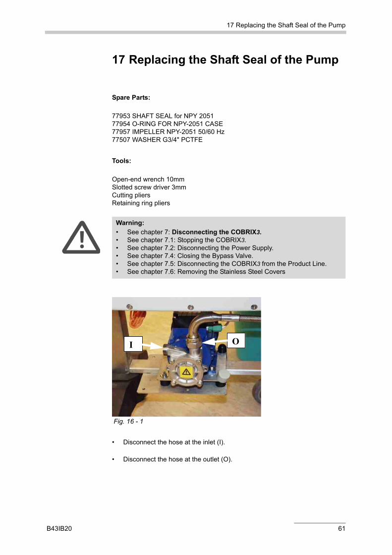
• Disconnect the hose at the inlet (I).
• Disconnect the hose at the outlet (O).
Warning:• See chapter 7: Disconnecting the COBRIX3.• See chapter 7.1: Stopping the COBRIX3.• See chapter 7.2: Disconnecting the Power Supply.• See chapter 7.4: Closing the Bypass Valve.• See chapter 7.5: Disconnecting the COBRIX3 from the Product Line.• See chapter 7.6: Removing the Stainless Steel Covers
Fig. 16 - 1
I O
B43IB20 61

17 Replacing the Shaft Seal of the Pump
(1): Lock ring
(2): Disk
(3): Spring
(4): Shaft seal part
(5): Counter ring
(6): O-ring
Fig. 16 - 2
Fig. 16 - 3
Open the pump cover:
Remove the hexagon screws from the pump casing. Take off the casing cover using the two screwdrivers from the pump casing.
Fig. 16 - 4
Remove the Impeller:
Remove the feather key. Pull off the impeller using the two screws. Remove the locking ring (1), disk (2) and spring (3).
62 B43IB20

17 Replacing the Shaft Seal of the Pump
Fig. 16 - 5
Fig. 16 - 6
Remove the casing:
Remove the pump casing from the motor shaft using the two screwdrivers.
Fig. 16 - 7
B43IB20 63

17 Replacing the Shaft Seal of the Pump
Press out the counter ring:
Press the counter ring (5) of the mechanical seal out the pump casing.
Fig. 16 - 8
Clean parts:
Clean the pump parts and the motor shaft. Clean the shaft with a lint-free cloth.
Fig. 16 - 9
Mount the shaft seal counter ring (5):
Lubricate the O-ring (6) with oil and press it into the pump casing. Place the pump casing on the motor flange and center it. Press the counter ring (5) over the motor shaft into the casing.
Fig. 16 - 10
64 B43IB20

17 Replacing the Shaft Seal of the Pump
• Check the smooth running of the pump by rotating the fan.
Fig. 16 - 11
Lubricate the seal rubber (4):
Lubricate the rubber of the shaft seal part (4) with oil. Caution: Do not lubricate the slide faces.
Mount the shaft seal part (4):
Press the part (4) slightly and without interruption up to the shaft seal counter part (5).
Fig. 16 - 12
Fig. 16 - 13
Mount the spring (3), disk (2) and lock ring (1). Insert the feather key into the shaft. Caution: Push to fit. Place the cover with the O-ring on the casing. Caution Observe the direction of the channel. Tighten the hexagon screws over cross.
B43IB20 65
17 Replacing the Shaft Seal of the Pump
Hint:• Use new seals when remounting the pump:
77954 O-RING FOR NPY-2051 CASE 77507 WASHER G3/4" PCTFE
• Check the impeller visually and replace it if necessary: 77957 IMPELLER NPY-2051 50/60 Hz
66 B43IB20

18 Replacing the Pump
18 Replacing the Pump
Spare Parts:
77385 CENTRIFUGAL PUMP NPY-2051 115V 50/60HZ77506 CENTRIFUGAL PUMP NPY-2051 230V 50/60HZ77507 WASHER G3/4" PCTFE
Tools:
Open-end wrench 10, 19 and 32 mmCutting pliersSnap-blade knife
• Disconnect the hose at the inlet (I).
• Disconnect the hose at the outlet (O).
• Disconnect the pump cable (C).
Warning:• See chapter 7: Disconnecting the COBRIX3.• See chapter 7.1: Stopping the COBRIX3.• See chapter 7.2: Disconnecting the Power Supply.• See chapter 7.4: Closing the Bypass Valve.• See chapter 7.5: Disconnecting the COBRIX3 from the Product Line.• See chapter 7.6: Removing the Stainless Steel Covers
I
C
O
Fig. 17 - 1
B43IB20 67

18 Replacing the Pump
• Open the four screws (4S).
• Replace the pump.
Important:To disconnect the pump cable it is not necessary to open the electronic box of the pump. Refer to chapter 18 “Disconnecting the Pump Cable”.
Fig. 17 - 2
4S
Hint:Use new seals when remounting the pump: 77507 WASHER G3/4" PCTFE
68 B43IB20

19 Disconnecting the Pump Cable
19 Disconnecting the Pump Cable
Tools:
Open-end wrench 19 mmCutting pliersSnap-blade knife
For the pump cable a quick connection system is used. Therefore, the cable (C) can be removed without opening the electronic box of the pump.
Removing the cable:
• Open the gland.
• Remove the conductor.
Warning:• See chapter 7: Disconnecting the COBRIX3.• See chapter 7.1: Stopping the COBRIX3.• See chapter 7.2: Disconnecting the Power Supply• See chapter 7.4: Closing the Bypass Valve.• See chapter 7.5: Disconnecting the COBRIX3 from the Product Line.• See chapter 7.6: Removing the Stainless Steel Covers
Fig. 18 - 1
C
B43IB20 69

• The conductor can be removed from the terminal point by pulling on the conductor.
• Surplus insulation must be removed before repeated connection.
Connecting the cable:
Observe in particular the following steps:
• Strip the sheath to a length of approx. 15 mm (see Fig. 18-2 part 1) and slide the union nut (1), the cap (2) and the rubber seal (3) onto the conductor.
• Slide the rubber seal as far as the rim of the insulation and then slide the cap onto the rubber seal. This provides the strain relief for the conductor (see Fig. 18-2 part 2).
• Insert the core ends into the feedthrough of the splice ring (see Fig. 18-2 part 3). To guarantee a clear assignment of the cores, the individual core feedthroughs of the splice ring are numbered (1, 2, ..).
• Cut off the projecting core ends. Make sure that the core ends are flush with the splice ring: They can protrude by up to 3 mm but must not be too short.
• Insert the prepared conductor into the contact carrier (4) (see Fig. 18-2 part 1). Turn the conductor with splice ring until the coding pins fit exactly into the corresponding guides (see Fig. 18-2 part 4).
• Close the gland by tightening the union nut. This presses the core ends into the insulation displacement terminal blocks, cuts open the core insulation and creates the electrical contact.
70 B43IB20

19 Disconnecting the Pump Cable
union nutcap
rubber sealcontact carrier
splice ring
Fig. 18 - 2 Connecting the pump cable
B43IB20 71
19 Disconnecting the Pump Cable
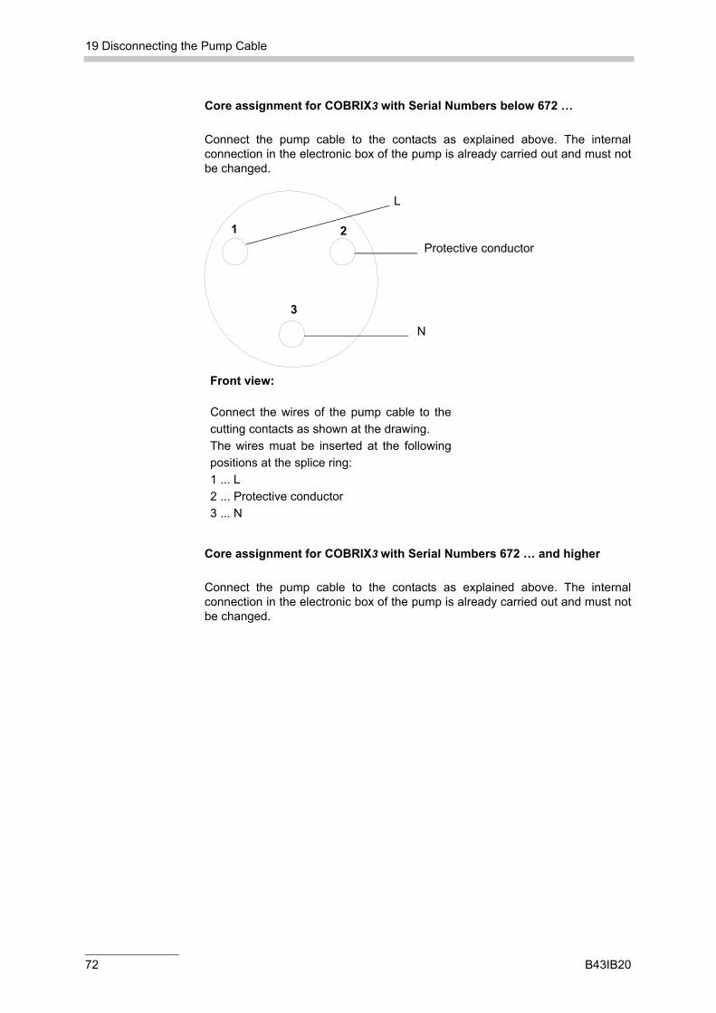
Core assignment for COBRIX3 with Serial Numbers below 672 …
Connect the pump cable to the contacts as explained above. The internal connection in the electronic box of the pump is already carried out and must not be changed.
Core assignment for COBRIX3 with Serial Numbers 672 … and higher
Connect the pump cable to the contacts as explained above. The internal connection in the electronic box of the pump is already carried out and must not be changed.
1 2
3
Front view:
Connect the wires of the pump cable to the cutting contacts as shown at the drawing. The wires muat be inserted at the following positions at the splice ring: 1 ... L 2 ... Protective conductor 3 ... N
Protective conductor
N
L
72 B43IB20

19 Disconnecting the Pump Cable
34
21
Front view:
Conect the wires of the pump cable to the cutting contacts as shown at the drawing . The wires must be inserted at the following positions at the splice ring: 1 ... L 2 ... Protective conductor 3 ... N 4 ... not used
N
Protective conductor
not used
L
B43IB20 73

74 B43IB20

20 Wetted Parts
20 Wetted Parts
Part.No Item Material
1 1910 BUTTERFLY VALVE DN25 SS 1.4571SS 1.4302EPDM
2 70769 WASHER 25MM DIN 32676 EPDM EPDM
3 10790 LIQUID SENSOR COBRIX3 PSUSS 1.4571EPDM
4 77390 ELBOW TUBE 90° DN 25 TRICLAMP SS 1.4404SS 1.4301
5 / FLEXIBLE HOSES SS 1.4571PTFE
6 7738577506
CENTRIFUGAL PUMP 115VCENTRIFUGAL PUMP 230V
SS 1.4581SS 1.4122SiC/ C/ VitonEPDMPeek
7 / DPRn or DSRn TRANSDUCER HastelloyC276
8 / CARBO 2100 CO2 TRANSDUCERRefer to the CARBO 2100 service manual
/
9 10775 SAMPLE VALVE COBRIX3 SS 1.4571SS 1.4404
B43IB20 75

76 B43IB20

21 List of Spare Parts for 1 Year of Operation
21 List of Spare Parts for 1 Year of Operation
Wearing parts:
The washers are wearing parts which should be replaced after opening the connection.
Part.No Item Quantity/1 System
Quantity/5 Systems
77385 CENTRIFUGAL PUMP NPY-2051115V 50/60HZ
1
77506 CENTRIFUGAL PUMP NPY-2051230V 50/60HZ
1
77953 SHAFT SEALFOR NPY-2051
1 2
77954 O-RINGFOR NPY-2051 CASE
1 2
77507 WASHER G3/4" PCTFE 2 6
77514 WASHER G3/8" PCTFE 4 12
70769 WASHER25MM DIN 32676 EPDM
3 9
10767 LIQUID SENSOR RELAY 115V 1
10766 LIQUID SENSOR RELAY 230V 1
10790 LIQUID SENSOR COBRIX3 1
10782 POWER SUPPLY 85-264VAC 24VDC 2.1A
1
10779 LAMP 24V 10 W Warning, Alarm
3
8434 RELAY 24V 1A EMG 12-REL/KSR 2
Hint:For spare parts of the CARBO 2100 refer to the service manual CARBO 2100.
B43IB20 77

21 List of Spare Parts for 1 Year of Operation
All other spare parts:
We suggest you keep the spare parts listed above on stock. Process equipment is often exposed to extreme working conditions which may cause unexpected failure.
78 B43IB20

22 List of Tools
22 List of Tools
Item Fig.
Key for the lock of the electronic housing 21-1
Cutting pliers 21-1
Retaining ring pliers 21-1
Snap-blade knife 21-1
Slotted screwdriver (3mm) 21-2
Allen screwdriver (3mm) 21-2
Pozidrive screwdriver (PZ 2x100) 21-2
Open-end wrench 10 mm 21-3
Open-end wrench 14 mm 21-3
Open-end wrench 17 mm 21-3
Open-end wrench 19 mm 21-3
Open-end wrench 32 mm 21-3
Fig. 21 - 1
B43IB20 79

22 List of Tools
Fig. 21 - 2
Fig. 21 - 3
80 B43IB20

23 Troubleshooting
23 Troubleshooting
General requirements:
- Liquid sensor The pump starts automatically if the liquid sensor defects sensor detects liquid in the line. Make sure that the liquid sensor is properly installed and that it switches the pump on when liquid is in the line.
- Empty lines at line shut down The COBRIX3 and bypass hoses must be installed so that the product runs out of the COBRIX3 bypass when the main line is empty. If the COBRIX3 bypass is not completely empty the liquid sensor switches the pump on and off frequently within a short time. This may cause the pump to overheat.
- Cleaning before emptying the line After production and before line shut down, all tubes and hoses must be properly cleaned with CIP. If CIP is not carried out product residues may stay in the pump and could clog the shaft seal. If a pump with clogged shaft seal is switched on, the retaining ring holding the shaft seal is stressed beyond specifications. This may destroy the pump.
- Electrical ratings of the pump motor Make sure that the power supply lies within the specified range given by the label on the motor. Frequent power failures may cause the motor to overheat.
Possible causes for motor failures and how to avoid them:
- Liquid entering the motor The motor will be destroyed by liquid entering its housing. The cover of the terminal box must be screwed on tightly. Cable glands in the terminal box must be tight. Absolutely no liquid must be splashed on the motor because liquid may enter the pump through the bearings.
- Damaged motor bearings If product or other liquids are splashed on the motor, the bearings may clog. Always use the pump cover and do not splash any liquid on the motor. Do not use steam jet cleaner!
- The pump periodically switching on and off If the pump switches on and off several times within a short period the motor may be overheated. Make sure that the liquid in the COBRIX3
B43IB20 81

23 Troubleshooting
bypass runs off when the main line is empty.
- Power supply Frequent power failures can cause the motor to overheat. Make sure that the specified power ratings are not exceeded. If the mains voltage is unstable, use a UPS or take other measures to stabilize the voltage.
- Clogged shaft seals If the main line is emptied before cleaning, product residues may remain in the pump. This may clog the shaft seal. If a pump with clogged shaft seal is switched on, the retaining ring holding the shaft is stressed beyond specifications. This may destroy the pump. Clean the bypass with CIP before line shut down!
- Solid particles in the pump Solid particles (metal filings, etc.), as may occur during putting into operation or after repair work, can damaged the impeller inside the pump. Use the Triclamp filter when putting into operation and when changing the piping anywhere along this main line.
Please refer to the following instruction manuals for further details:
1. COBRIX3 instruction manual
2. mPDS 2000V3 instruction manual
3. DPRn density transducer or
4. DSRn density sound velocity transducer instruction manual
5. CARBO 2100 CO2 transducer instruction manual
82 B43IB20

24 Document Numbers
24 Document Numbers
Document number Date Comment
B43IB20A 10.04.2003 First release
B43IB20B 22.10.2003 Minor changes
B43IB20C 23.06.2004 Change the default settings of the optional LED Display
B43IB20 83

Appendix A: Service/Maintenance Report
Appendix A: Service/Maintenance Report
see next pages:
84 B43IB20

Appendix A: Service/Maintenance Report
COBRIX3 Preventive Maintenance Protocol
Maintenance protocol
COBRIX serial number
Maintenance contract No.
Field of operation
Temperature range
Bypass pump Type S/no.
Density/velocity of sound transducer DPRn 427 DSRn 427
Serial number
CO2 transducer CARBO 2100
Serial number of transducer
COBRIX evaluation unit mPDS 2000 V
Serial number
Application program
Company:
Name:
Address:
Post code – City:
COBRIX
Anton Paar GmbH
Anton-Paar-Str. 20, A-8054 Graz, Austria – Europe Tel: +43 316 257-0, Fax: +43 316 257-257 E-mail: [email protected]
Instruments for: - Density and concentration measurement - Rheometry and viscometry- High-precision temperature measurement - X-ray structure analysis
- Microhardness testing - Sample preparation- CO2 measurement - Colloid science
Web: www.anton-paar.com
B43IE31B-E-MaintenanceProtocol-Cobrix3.doc Page 1 of 5
B43IB20 85

Appendix A: Service/Maintenance Report
COBRIX3 Preventive Maintenance Protocol
CobrixCOBRIX
Accessories (connected to the Anton Paar COBRIX evaluation unit):
Flow monitor “Filler stopped” signal
Bottle counter 3# LED displays
Product selector Davis Software Version
Additional measurements Type
Control functions Type
Regulating functions Type
External condition of the instrument before maintenance:
COBRIX housing and rack: OK not OK cleaned
CO2 transducer: OK not OK cleaned
DPR/DSR transducer: OK not OK cleaned
Bypass pump: OK not OK cleaned
Comment:
Checking the configuration / Setting the parameters:
CARBO 2100 settings:
Unit: g/l vol
Prod.: BE SD MW SW CS
Presetting: Carbo-dV Carbo-dT Carbo-dP
Adjustment factors: CO2-Offset CO2-Gain
COBRIX evaluation unit:
Instrument constants DPR/DSR transducer
Acc. to data sheet from: OK not OK
Comment:
System data saved: yes no not applicable
File name:
After discussing with the customer, the COBRIX measuring system has been separated from the
production line
B43IE31B-E-MaintenanceProtocol-Cobrix3.doc Page 2 of 5
86 B43IB20

Appendix A: Service/Maintenance Report
COBRIX3 Preventive Maintenance Protocol
CobrixCOBRIX
Checking / maintenance of the Carbo 2100
Checking / cleaning Cable connections Control valve for compressed air
Pneumatic connections Pneumatic valves Magnetic valves
Stirrer Temperature sensor Pressure sensor
Functional test
Checking / maintenance of the COBRIX evaluation unit
Visual check OK not OK
Contacts maintenance carried
out
yes no
Buffer battery OK not OK not measurable VDC
Digital inlets OK not OK not applicable
Analog inlets OK not OK not applicable
Digital outlets OK not OK not applicable
Analog outlets OK not OK not applicable
Counter inlets OK not OK not applicable
Relay outlets OK not OK not applicable
DPR/DSR inlet OK not OK not applicable
Product selection OK not OK not applicable
Checking / maintenance of the DPRn/DSRn transducer
Power supply voltage OK not OK VDC
Visual check of measuring electronics OK not OK
Seal on electronic housing OK not OK replaced
Checking / maintenance of the bypass pump
Mechanical seal replaced yes no
Functional test OK not OK
B43IE31B-E-MaintenanceProtocol-Cobrix3.doc Page 3 of 5
B43IB20 87

Appendix A: Service/Maintenance Report
COBRIX3 Preventive Maintenance Protocol
CobrixCOBRIX
The customer was informed that the transducer has been separated from the production line for the
maintenance procedures and can only be operated again after successful cleaning (CIP):
yes no
Checking the Brix/Diet adjustment
Current product:
Reference method
Brix/Diet conc. reference Temp. °C
Brix/Diet conc. COBRIX Temp. °C
Deviation
Checking the CO2 adjustment
Current product
Reference method
CO2 conc. reference
CO2 conc. Carbo P-Line bar P-Gas bar Temp. °C
CO2 deviation
Other maintenance carried out / comments:
Replaced parts for CARBO 2100:
PTFE pcs. 6924 Stirrer Igus/Two Wing pcs. 12745
Stirrer motor Igus pcs. 10745 valve Hubbegr. pcs. 6923
Absolute pressure sensor pcs. 6522 valve EPDM pcs. 12758
Temperature sensor pcs. 6521 EPDM pcs. 12759
Interface card new pcs. 9116 EPDM pcs. 13881
Magnetic valve pcs. 6525 EPDM pcs. 16772
B43IE31B-E-MaintenanceProtocol-Cobrix3.doc Page 4 of 5
88 B43IB20
Appendix A: Service/Maintenance Report
COBRIX3 Preventive Maintenance Protocol
CobrixCOBRIX
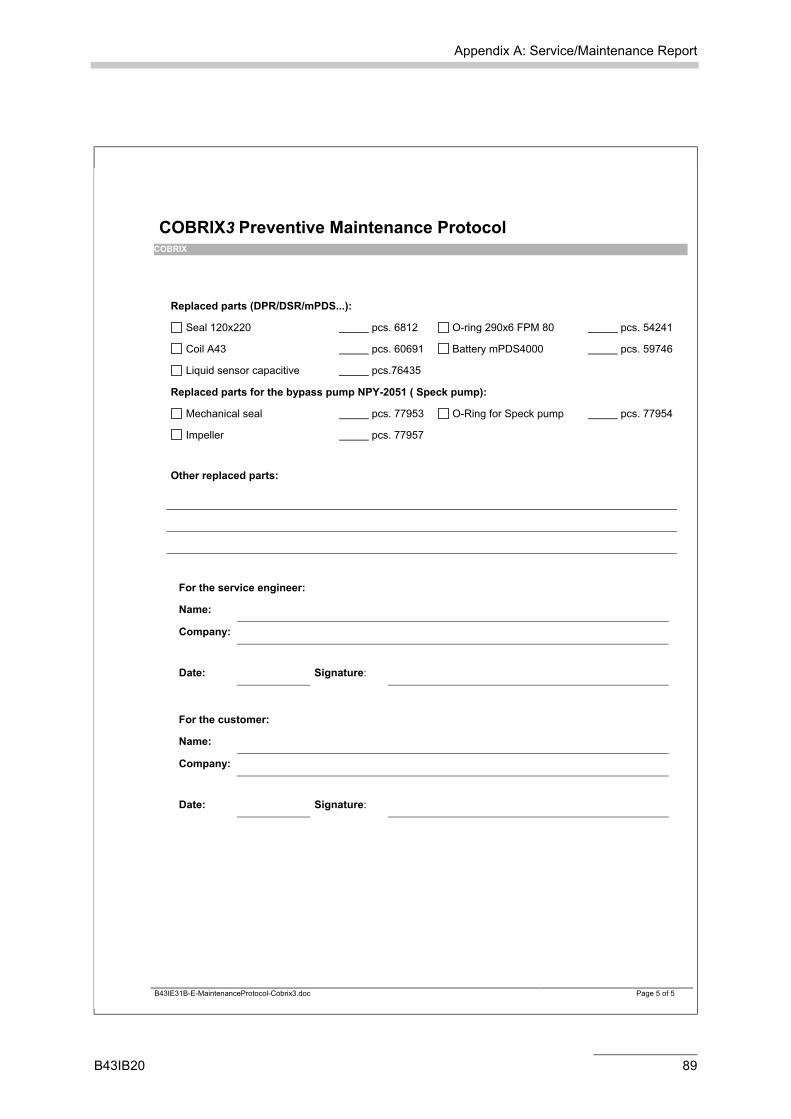
Replaced parts (DPR/DSR/mPDS...):
Seal 120x220 pcs. 6812 O-ring 290x6 FPM 80 pcs. 54241
Coil A43 pcs. 60691 Battery mPDS4000 pcs. 59746
Liquid sensor capacitive pcs.76435
Replaced parts for the bypass pump NPY-2051 ( Speck pump):
Mechanical seal pcs. 77953 O-Ring for Speck pump pcs. 77954
Impeller pcs. 77957
Other replaced parts:
For the service engineer:
Name:
Company:
Date: Signature:
For the customer:
Name:
Company:
Date: Signature:
B43IE31B-E-MaintenanceProtocol-Cobrix3.doc Page 5 of 5
B43IB20 89

Appendix B: Feedback Form
Appendix B: Feedback Form
Please help us improve this service manual and our service to you!
If you have any suggestions, comments or problems concerning the contents of this service manual, please do not hesitate to contact us:
E-mail: [email protected] or copy and fax this form to: +43-316-257-257
Service manual for instrument type:...................................................................
Name and address: ....................................................................................... .............................................................................................................................................................................................................................................................................................................................................................................................
The service manual should contain more information on:
...............................................................................................................................
...............................................................................................................................
...............................................................................................................................
...............................................................................................................................
...............................................................................................................................
...............................................................................................................................
The following sections are difficult to understand:
...............................................................................................................................
...............................................................................................................................
...............................................................................................................................
...............................................................................................................................
...............................................................................................................................
...............................................................................................................................
Other comments:
...............................................................................................................................
...............................................................................................................................
...............................................................................................................................
...............................................................................................................................
...............................................................................................................................
...............................................................................................................................
.............................................................................................................................
Thank you for your feedback!
90 B43IB20